Power Management Selection Guide, 2Q 2007
Power Management Selection Guide, 2Q 2007
Power Management Selection Guide, 2Q 2007

You also want an ePaper? Increase the reach of your titles
YUMPU automatically turns print PDFs into web optimized ePapers that Google loves.
Technology for Innovators TM<br />
<strong>Power</strong> <strong>Management</strong> <strong>Selection</strong> <strong>Guide</strong><br />
<strong>2Q</strong> <strong>2007</strong>
2 <strong>Power</strong> <strong>Management</strong> <strong>Selection</strong> <strong>Guide</strong><br />
➔<br />
Table of Contents<br />
Texas Instruments (TI) offers complete power<br />
solutions with a full line of high-performance<br />
products. These products, which range from<br />
standard linear ICs to plug-in and integrated<br />
power solutions, are tailored to meet your<br />
design challenges. And, TI makes designing<br />
easier by providing leading-edge support<br />
tools such as training, a broad selection of<br />
evaluation modules (EVMs), application<br />
notes, comprehensive technical documentation<br />
and more. TI also offers samples and<br />
small orders (shipped within 24 hours via TI<br />
authorized distributors) that will help you<br />
accelerate your time-to-market.<br />
Included in this selection guide you will find<br />
design factors, featured products, graphic<br />
representations of portfolios and parametric<br />
tables. A list of application notes and evaluation<br />
modules is included in each section of<br />
the guide.<br />
TI <strong>Power</strong> Solutions:<br />
<strong>Power</strong> Behind<br />
Your Designs<br />
TI provides power management integration,<br />
technology and value to help you<br />
drive innovation and grow market<br />
opportunities. This is coupled with<br />
collaboration, tools, service and delivery<br />
to help you get there faster. For more<br />
information or technical assistance,<br />
please see TI Worldwide Technical<br />
Support on page 75 of this selection<br />
guide or visit TI’s <strong>Power</strong> <strong>Management</strong><br />
web site at:<br />
power.ti.com<br />
Note: Military versions of some <strong>Power</strong> <strong>Management</strong><br />
products are available. Please visit:<br />
power.ti.com/militaryproducts<br />
Typical <strong>Power</strong> Applications 3<br />
Line <strong>Power</strong> Solutions . . . . . . . . . . . . . . . . . . . . . . . . . . . . . . . . . . . . . . . . . . . . . . . . . . . . . . . . . . . . . . .3<br />
Portable <strong>Power</strong> Solutions . . . . . . . . . . . . . . . . . . . . . . . . . . . . . . . . . . . . . . . . . . . . . . . . . . . . . . . . . . .3<br />
AC/DC Solutions . . . . . . . . . . . . . . . . . . . . . . . . . . . . . . . . . . . . . . . . . . . . . . . . . . . . . . . . . . . . . . . . . .4<br />
Isolated DC/DC Solutions . . . . . . . . . . . . . . . . . . . . . . . . . . . . . . . . . . . . . . . . . . . . . . . . . . . . . . . . . . .4<br />
FPGA and CPLD <strong>Power</strong> Solutions . . . . . . . . . . . . . . . . . . . . . . . . . . . . . . . . . . . . . . . . . . . . . . . . . . . . .5<br />
DSP <strong>Power</strong> Solutions . . . . . . . . . . . . . . . . . . . . . . . . . . . . . . . . . . . . . . . . . . . . . . . . . . . . . . . . . . . . . . .7<br />
Active-Bus Termination Solutions . . . . . . . . . . . . . . . . . . . . . . . . . . . . . . . . . . . . . . . . . . . . . . . . . . . . .9<br />
Fusion Digital <strong>Power</strong> Control Solutions 10<br />
Introduction and Digital <strong>Power</strong> Drivers . . . . . . . . . . . . . . . . . . . . . . . . . . . . . . . . . . . . . . . . . . . . . . . .10<br />
Digital PWM Controllers . . . . . . . . . . . . . . . . . . . . . . . . . . . . . . . . . . . . . . . . . . . . . . . . . . . . . . . . . . .12<br />
<strong>Power</strong>-Supply Sequencer . . . . . . . . . . . . . . . . . . . . . . . . . . . . . . . . . . . . . . . . . . . . . . . . . . . . . . . . . . .13<br />
AC/DC and DC/DC <strong>Power</strong> Supply Products 14<br />
<strong>Power</strong> Factor Correction (PFC) . . . . . . . . . . . . . . . . . . . . . . . . . . . . . . . . . . . . . . . . . . . . . . . . . . . . . . .14<br />
PWM <strong>Power</strong> Supply Controllers . . . . . . . . . . . . . . . . . . . . . . . . . . . . . . . . . . . . . . . . . . . . . . . . . . . . .16<br />
MOSFET Drivers . . . . . . . . . . . . . . . . . . . . . . . . . . . . . . . . . . . . . . . . . . . . . . . . . . . . . . . . . . . . . . . . . .22<br />
Loadshare Controllers . . . . . . . . . . . . . . . . . . . . . . . . . . . . . . . . . . . . . . . . . . . . . . . . . . . . . . . . . . . . .24<br />
Plug-In <strong>Power</strong> Modules (POLA and Others) 25<br />
Linear Regulators 28<br />
Non-Isolated Switching DC/DC Regulators 32<br />
DC/DC Controllers (External Switch) . . . . . . . . . . . . . . . . . . . . . . . . . . . . . . . . . . . . . . . . . . . . . . . . . .32<br />
DC/DC Converters (Integrated Switch) . . . . . . . . . . . . . . . . . . . . . . . . . . . . . . . . . . . . . . . . . . . . . . . .34<br />
Inductorless DC/DC Regulators (Charge Pumps) . . . . . . . . . . . . . . . . . . . . . . . . . . . . . . . . . . . . . . . .39<br />
Application-Specific Multi-Output Solutions 41<br />
Lighting Solutions 42<br />
White LED Drivers . . . . . . . . . . . . . . . . . . . . . . . . . . . . . . . . . . . . . . . . . . . . . . . . . . . . . . . . . . . . . . . .42<br />
LED Drivers . . . . . . . . . . . . . . . . . . . . . . . . . . . . . . . . . . . . . . . . . . . . . . . . . . . . . . . . . . . . . . . . . . . . .43<br />
CCFL Backlight Controllers . . . . . . . . . . . . . . . . . . . . . . . . . . . . . . . . . . . . . . . . . . . . . . . . . . . . . . . . .44<br />
Photoflash Capacitor Chargers . . . . . . . . . . . . . . . . . . . . . . . . . . . . . . . . . . . . . . . . . . . . . . . . . . . . . .45<br />
Battery <strong>Management</strong> Products 46<br />
Battery Charge <strong>Management</strong> . . . . . . . . . . . . . . . . . . . . . . . . . . . . . . . . . . . . . . . . . . . . . . . . . . . . . . .46<br />
Battery Fuel Gauges . . . . . . . . . . . . . . . . . . . . . . . . . . . . . . . . . . . . . . . . . . . . . . . . . . . . . . . . . . . . . .48<br />
Lithium-Ion Protection . . . . . . . . . . . . . . . . . . . . . . . . . . . . . . . . . . . . . . . . . . . . . . . . . . . . . . . . . . . . .50<br />
Authentication for Batteries and Peripherals . . . . . . . . . . . . . . . . . . . . . . . . . . . . . . . . . . . . . . . . . . .51<br />
Hot Swap and <strong>Power</strong> Distribution 51<br />
<strong>Power</strong>-over-Ethernet . . . . . . . . . . . . . . . . . . . . . . . . . . . . . . . . . . . . . . . . . . . . . . . . . . . . . . . . . . . . . .51<br />
Hot Swap <strong>Power</strong> <strong>Management</strong> . . . . . . . . . . . . . . . . . . . . . . . . . . . . . . . . . . . . . . . . . . . . . . . . . . . . . .53<br />
PCMCIA and USB Devices . . . . . . . . . . . . . . . . . . . . . . . . . . . . . . . . . . . . . . . . . . . . . . . . . . . . . . . . . .56<br />
<strong>Power</strong> Multiplexers and Current-Limiting Switches . . . . . . . . . . . . . . . . . . . . . . . . . . . . . . . . . . . . . .59<br />
Supervisory Circuits (Voltage Supervisors) 61<br />
Voltage References 63<br />
<strong>Power</strong> <strong>Management</strong> Special Functions 65<br />
Real-Time Clocks . . . . . . . . . . . . . . . . . . . . . . . . . . . . . . . . . . . . . . . . . . . . . . . . . . . . . . . . . . . . . . . . .65<br />
Non-Volatile SRAM (NVSRAM) . . . . . . . . . . . . . . . . . . . . . . . . . . . . . . . . . . . . . . . . . . . . . . . . . . . . . .66<br />
Resources 67<br />
Design Support . . . . . . . . . . . . . . . . . . . . . . . . . . . . . . . . . . . . . . . . . . . . . . . . . . . . . . . . . . . . . . . . . .67<br />
Packaging . . . . . . . . . . . . . . . . . . . . . . . . . . . . . . . . . . . . . . . . . . . . . . . . . . . . . . . . . . . . . . . . . . . . . . .70<br />
Device Index . . . . . . . . . . . . . . . . . . . . . . . . . . . . . . . . . . . . . . . . . . . . . . . . . . . . . . . . . . . . . . . . . . . .72<br />
TI Worldwide Technical Support . . . . . . . . . . . . . . . . . . . . . . . . . . . . . . . . . . . . . . . . . . . . . . . . . . . . .75<br />
<strong>Power</strong> <strong>Management</strong> <strong>Selection</strong> <strong>Guide</strong> Texas Instruments <strong>2Q</strong> <strong>2007</strong>
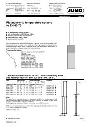
Typical <strong>Power</strong> Applications 3<br />
Line <strong>Power</strong> Solutions<br />
Backplane<br />
➔<br />
AC<br />
Line<br />
<strong>Power</strong> Factor<br />
Correction<br />
or AC/DC<br />
(Page 14)<br />
PWM<br />
Controllers<br />
(Page 16)<br />
MOSFET<br />
Drivers<br />
(Page 22)<br />
Hot Swap<br />
and<br />
<strong>Power</strong>-over-Ethernet<br />
(Page 51)<br />
Non-Isolated<br />
Plug-In<br />
Modules<br />
POLA<br />
(Page 25)<br />
<strong>Power</strong><br />
Switches<br />
USB<br />
ExpressCard<br />
PCMCIA<br />
(Page 56)<br />
USB<br />
Peripheral<br />
+<br />
48-V<br />
–<br />
48-V or 24-V<br />
DC Input<br />
Isolated<br />
Plug-In<br />
Modules<br />
(Page 25)<br />
UCD9080<br />
8-Channel<br />
<strong>Power</strong>-Supply<br />
Sequencer<br />
(Page 13)<br />
DC/DC<br />
Controller<br />
(Page 32)<br />
DC/DC<br />
Converter<br />
(Page 34)<br />
Supply<br />
Voltage<br />
Supervisor<br />
(Page 61)<br />
System<br />
Voltage<br />
Hard Drive<br />
DSP<br />
DSP/µC<br />
Low Dropout<br />
Regulator<br />
(Page 28)<br />
Memory<br />
Portable <strong>Power</strong> Solutions<br />
Audio Supply<br />
Noise-Sensitive<br />
RF Circuitry<br />
Step-Up DC/DC<br />
Converters<br />
(Page 34)<br />
Inductorless<br />
DC/DC Regulators<br />
(Charge Pumps)<br />
(Page 39)<br />
Application-Specific<br />
Multi-Output<br />
Solutions<br />
(Page 41)<br />
Photoflash<br />
Capacitor Chargers<br />
(Page 45)<br />
White LED Drivers<br />
(Page 42)<br />
System<br />
Voltages<br />
Photo Flash<br />
LED Light<br />
DC<br />
Inputs<br />
USB<br />
Battery <strong>Management</strong><br />
Battery Charge<br />
<strong>Management</strong><br />
(Page 46)<br />
Lithium-Ion<br />
Protection and<br />
Authentication<br />
for Batteries<br />
(Pages 50, 51)<br />
Application-Specific<br />
Multi-Output<br />
Solutions<br />
(Page 41)<br />
Linear Regulators<br />
(Page 28)<br />
Step-Down<br />
DC/DC Converters<br />
(Page 34)<br />
LCD Color<br />
Display<br />
Memory<br />
Supervisory Circuits<br />
(Voltage Supervisors)<br />
(Page 61)<br />
Rechargeable<br />
Battery<br />
Battery<br />
Fuel Gauges<br />
(Page 48)<br />
I 2 C<br />
DSP<br />
µC<br />
Reset<br />
Texas Instruments <strong>2Q</strong> <strong>2007</strong><br />
<strong>Power</strong> <strong>Management</strong> <strong>Selection</strong> <strong>Guide</strong>
4<br />
Typical <strong>Power</strong> Applications<br />
➔<br />
AC/DC Solutions<br />
Isolated DC/DC Solutions<br />
AC Line:<br />
85 to 265-V AC<br />
Rectified AC<br />
385 to 400-V<br />
Boosted DC<br />
Output<br />
<strong>Power</strong> Factor<br />
Correction<br />
(Page 14)<br />
PFC<br />
UCC28019<br />
UCC38050/51<br />
UCC3817A/18A<br />
UCC3819A<br />
UC3854/A/B<br />
UC3855A/B<br />
PFC + PWM<br />
UCC38500-3<br />
UCC28510-7<br />
UCC28521/28<br />
PWM<br />
Controllers<br />
(Page 16)<br />
PWM (Forward,<br />
Flyback)<br />
UCC28220/1<br />
UCC28600<br />
UCC2891/2/3/4/7<br />
UCC35701/2<br />
UCC35705/6<br />
UCC3800-5<br />
UCC3809<br />
UCC3813-x<br />
UCC38C40-45<br />
PWM<br />
(Half-Bridge,<br />
Full-Bridge,<br />
Push-Pull)<br />
UCC3895<br />
UCC38083-6<br />
UCC3806<br />
UCC3808/A<br />
UC3825/A<br />
UC28025<br />
UCD8220/8620<br />
Primary Side<br />
Startup<br />
UCC3960/61<br />
MOSFET<br />
Drivers<br />
(Page 22)<br />
±2 A<br />
TPS2811-15<br />
TPS2816-19<br />
TPS2828-29<br />
±3 A<br />
UCC27200<br />
UCC27201<br />
±4 A<br />
UCC37323/4/5<br />
UCC27423/4/5<br />
UCD7201<br />
UCD7100<br />
±9 A<br />
UCC37321/2<br />
Isolation<br />
Feedback<br />
(Page 63)<br />
Shunt<br />
Regulators<br />
TL431/A<br />
TLV431/A<br />
TL1431<br />
UC39431/2<br />
Secondary<br />
Side Control<br />
(Page 16, 22)<br />
PWM<br />
UC3849<br />
UCC3839<br />
Drivers<br />
TPS2811-15<br />
TPS28225<br />
TPS28226<br />
TPS2829-29<br />
UCC27423/4/5<br />
UCC37321/2<br />
UCC37323/4/5<br />
UCD7100<br />
UCD7201<br />
Post<br />
Regulation<br />
(Page 16, 28)<br />
PWM<br />
UCC2540<br />
UCC3583<br />
LDOs<br />
TPS7xxx<br />
UC382/385<br />
Loadshare<br />
(Page 24)<br />
Loadshare<br />
UCC39002<br />
UC3907<br />
UC3902<br />
PWM +<br />
Loadshare<br />
UC3849<br />
Bus Voltage<br />
3.3 to 48 V<br />
<strong>Power</strong> <strong>Management</strong> <strong>Selection</strong> <strong>Guide</strong> Texas Instruments <strong>2Q</strong> <strong>2007</strong>
Typical <strong>Power</strong> Applications 5<br />
FPGA and CPLD <strong>Power</strong> Solutions<br />
www.ti.com/xilinxfpga or www.ti.com/alterafpga<br />
➔<br />
Access the sites for one-stop power management support for Xilinx ® and Altera ® FPGAs and CPLDs, including free downloads of power reference<br />
designs with complete schematics, bills-of-material and helpful implementation notes.<br />
Highly Integrated TPS75003 Triple Supply <strong>Power</strong>ing Spartan-3<br />
5V_INPUT<br />
100 µF<br />
V CCAUX<br />
1.5 nF<br />
IN1<br />
IN2<br />
IN3<br />
EN1<br />
SS1<br />
EN2<br />
SS2<br />
EN3<br />
SS3<br />
DGND<br />
TPS75003<br />
3-A<br />
BUCK1<br />
3-A<br />
BUCK2<br />
300-mA<br />
LDO<br />
IS1<br />
SW1<br />
FB1<br />
IS2<br />
SW2<br />
FB2<br />
OUT3<br />
FB3<br />
AGND<br />
DGND<br />
DGND<br />
0.033 Ω<br />
0.033 Ω<br />
Q2<br />
15 µH<br />
D2<br />
Q1 5 µH<br />
+<br />
V CCINT<br />
1.2 V @ 2 A<br />
100 µF<br />
1.5 nF<br />
10 nF<br />
D1<br />
61.9 kΩ<br />
+<br />
V CCO<br />
3.3 V @ 2 A<br />
100 µF<br />
36.5 kΩ<br />
Two Highly Efficient TPS54610 6-A SWIFT DC/DC<br />
Converters <strong>Power</strong>ing Stratix ® II<br />
61.9 kΩ<br />
V CCAUX<br />
2.5 V @ 300 mA<br />
10 µF<br />
5V_INPUT<br />
C2<br />
0.047 µF<br />
C6 +<br />
10 µF<br />
C4 0.1 µF<br />
C7<br />
220 µF<br />
28<br />
27<br />
26<br />
25<br />
24<br />
23<br />
22<br />
21<br />
20<br />
19<br />
18<br />
17<br />
16<br />
15<br />
U1<br />
TPS54610PWP<br />
RT<br />
SYNCH<br />
SS/ENA<br />
VBIAS<br />
VIN<br />
VIN<br />
VIN<br />
VIN<br />
VIN<br />
PGND<br />
PGND<br />
PGND<br />
PGND<br />
PGND<br />
ANAGND<br />
VSENSE<br />
COMP<br />
PWRGD<br />
BOOT<br />
PH<br />
PH<br />
PH<br />
PH<br />
PH<br />
PH<br />
PH<br />
PH<br />
PH<br />
PWRPAD<br />
1<br />
2<br />
3<br />
4<br />
5<br />
6<br />
7<br />
8<br />
9<br />
10<br />
11<br />
12<br />
13<br />
14<br />
C3<br />
C5<br />
C8<br />
0.047 µF<br />
R1<br />
14.7 kΩ<br />
68 pF<br />
6800 pF<br />
R3<br />
L1 9.76 kΩ<br />
4.7 µH<br />
+<br />
R2<br />
1.18 kΩ<br />
C9<br />
470 µF<br />
4 V<br />
R4<br />
10.0 kΩ<br />
+<br />
C1<br />
0.012 µF<br />
C10<br />
470 µF<br />
4 V<br />
1.5 V at 6 A<br />
DIGITAL_VCCINT<br />
15.4 kΩ<br />
C12<br />
0.047 µF<br />
C14 0.1 µF<br />
C16 +<br />
10 µF<br />
R9<br />
10.0 kΩ<br />
C17<br />
220 µF<br />
28<br />
27<br />
26<br />
25<br />
24<br />
23<br />
22<br />
21<br />
20<br />
19<br />
18<br />
17<br />
16<br />
15<br />
U2<br />
TPS54610PWP<br />
RT<br />
SYNCH<br />
SS/ENA<br />
VBIAS<br />
VIN<br />
VIN<br />
VIN<br />
VIN<br />
VIN<br />
PGND<br />
PGND<br />
PGND<br />
PGND<br />
PGND<br />
ANAGND<br />
VSENSE<br />
COMP<br />
PWRGD<br />
BOOT<br />
PH<br />
PH<br />
PH<br />
PH<br />
PH<br />
PH<br />
PH<br />
PH<br />
PH<br />
PWRPAD<br />
1<br />
2<br />
3<br />
4<br />
5<br />
6<br />
7<br />
8<br />
9<br />
10<br />
11<br />
12<br />
13<br />
14<br />
C13<br />
C15<br />
C18<br />
0.047 µF<br />
R5<br />
3.74 kΩ<br />
68 pF<br />
6800 pF<br />
R7<br />
L2 9.76 kΩ<br />
4.7 µH<br />
+<br />
R6<br />
1.18 kΩ<br />
C19<br />
470 µF<br />
4 V<br />
R8<br />
10.0 kΩ<br />
+<br />
C11<br />
0.012 µF<br />
C20<br />
470 µF<br />
4 V<br />
3.3 V at 6 A<br />
DIGITAL_VCCIO<br />
PLL_ENABLE<br />
Texas Instruments <strong>2Q</strong> <strong>2007</strong><br />
<strong>Power</strong> <strong>Management</strong> <strong>Selection</strong> <strong>Guide</strong>
6<br />
Typical <strong>Power</strong> Applications<br />
➔<br />
Multiple T2 Modules with Frequency Synchronization via SmartSync<br />
and Sequenced with Auto-Track <strong>Power</strong> Xilinx ® Virtex ® 5 FPGA<br />
SmartSync<br />
5-V<br />
Supply<br />
Sense V DD Reset<br />
TPS3808G33<br />
3.3-V SVS<br />
(25-ms Delay)<br />
CT<br />
GND<br />
MR<br />
+<br />
Auto-Track<br />
470 µF<br />
10 µF 10 µF<br />
V IN<br />
Track SYNC TT<br />
+Sense<br />
PTH08T240W<br />
V<br />
(87% Efficiency) OUT<br />
INH/UVLO<br />
UVLO<br />
Adj.<br />
GND<br />
V OUT Adj<br />
–Sense<br />
R SET<br />
20.5 kΩ<br />
(1%)<br />
+<br />
2.74 kΩ<br />
1000 µF +<br />
(ESR =<br />
5 to 10 mΩ)<br />
1000 µF<br />
(ESR =<br />
5 to 10 mΩ)<br />
1 V at 10 A<br />
Maximum<br />
10 µF<br />
4700 pF<br />
GND<br />
SmartSync<br />
SmartSync<br />
Control<br />
(240 kHz with<br />
Phase Shift)<br />
+<br />
Auto-Track<br />
470 µF<br />
2.2 µF 22 µF<br />
V IN<br />
Track SYNC TT<br />
+Sense<br />
PTH08T230W<br />
V<br />
(94% Efficiency) OUT<br />
INH/UVLO<br />
UVLO<br />
Adj.<br />
GND<br />
V OUT Adj<br />
–Sense<br />
R SET<br />
1.21 kΩ<br />
(1%)<br />
+<br />
23.2 kΩ<br />
680 µF +<br />
(ESR =<br />
5 to 10 mΩ)<br />
200 µF<br />
Ceramic<br />
3.3 V at 6 A<br />
Maximum<br />
GND<br />
SmartSync<br />
+<br />
Auto-Track<br />
470 µF<br />
2.2 µF 22 µF<br />
V IN<br />
Track SYNC TT<br />
+Sense<br />
PTH08T230W<br />
V<br />
(88% Efficiency) OUT<br />
INH/UVLO<br />
UVLO<br />
Adj.<br />
GND<br />
V OUT Adj<br />
–Sense<br />
R SET<br />
1.21 kΩ<br />
(1%)<br />
+<br />
23.2 kΩ<br />
100 pF +<br />
(ESR =<br />
5 to 10 mΩ)<br />
200 µF<br />
Ceramic<br />
1.8 V at 6 A<br />
Maximum<br />
GND<br />
VDDQ 1.8 V<br />
1 µF<br />
V IN<br />
S5<br />
GND<br />
S3<br />
VTTREF<br />
TPS51100DGQ<br />
DDR<br />
<strong>Power</strong>PAD<br />
VDDQSNS<br />
VLDOIN<br />
VTT<br />
PGND<br />
VTTSNS<br />
10 µF<br />
10 µF<br />
VTTDDR<br />
0.9 V at 1.4 A<br />
0.1 µF<br />
10 µF<br />
1 µF<br />
IN<br />
EN<br />
BIAS<br />
SS<br />
TPS74401<br />
2.5 V<br />
GND<br />
1 µF 0.001 µF<br />
(1-ms <strong>Power</strong> Up)<br />
PG<br />
OUT<br />
FB<br />
10 kΩ<br />
R1<br />
R2<br />
<strong>Power</strong><br />
Good<br />
R1 = 1.69 kΩ (1%)<br />
R2 = 3.57 kΩ (1%)<br />
Flash<br />
Reset<br />
2.5 V<br />
<strong>Power</strong> <strong>Management</strong> <strong>Selection</strong> <strong>Guide</strong> Texas Instruments <strong>2Q</strong> <strong>2007</strong>
Typical <strong>Power</strong> Applications 7<br />
DSP <strong>Power</strong> Solutions<br />
www.ti.com/dsppower<br />
Access the site for one-stop DSP power management support, including free downloads of DSP power reference designs with complete<br />
schematics, bill-of-materials and helpful implementation notes.<br />
6-Channel <strong>Power</strong> <strong>Management</strong> IC with 3 DC/DCs, 3 LDOs, I 2 C Interface<br />
and DVS, Optimized for DaVinci DSPs<br />
V IN<br />
DSP_EN<br />
➔<br />
V IN<br />
10 Ω<br />
1 µF<br />
V CC<br />
TPS65023<br />
4.7 kΩ<br />
4.7 kΩ<br />
DaVinci<br />
TMS320DM644x<br />
VDCDC3<br />
V IN<br />
VDCDC3<br />
EN<br />
V IN<br />
1 µF<br />
4.7 µF<br />
10 µF<br />
10 µF<br />
10 µF<br />
100 kΩ<br />
1 nF<br />
100 kΩ<br />
100 kΩ<br />
VINDCDC1<br />
VINDCDC2<br />
VINDCDC3<br />
VIN_LDO<br />
LOW_BATT<br />
PWRFAIL_SNS<br />
LOWBAT_SNS<br />
HOT_RESET<br />
TRESPWRON<br />
DEFLDO1<br />
DEFLDO2<br />
LDO_EN<br />
VSYSIN<br />
VBACKUP<br />
VRTC<br />
PWRFAIL<br />
DCDC2_EN<br />
DCDC1_EN<br />
DCDC3_EN<br />
DEFDCDC3<br />
DEFDCDC2<br />
DEFDCDC1<br />
SCLK<br />
SDAT<br />
INT<br />
VDCDC1<br />
L1<br />
VDCDC2<br />
L2<br />
LDO1<br />
LDO2<br />
VDCDC3<br />
L3<br />
RESPWRON<br />
AGND1<br />
AGND2<br />
PGND1<br />
PGND2<br />
PGND3<br />
100 kΩ<br />
2.2 µH<br />
2.2 µH<br />
2.2 µH<br />
22 µF<br />
22 µF<br />
2.2 µF<br />
2.2 µF<br />
22 µF<br />
100 kΩ<br />
SCLK<br />
SDAT<br />
CVDDDSP<br />
USB_VDD1P2LDO<br />
CVDD<br />
APLLREFV<br />
VDDA_1P1V<br />
DVD18<br />
DVDDR2<br />
VDDA_1P8V<br />
USB_VDD1P8<br />
M24VDD<br />
PLLVDD18<br />
DDR_VDDDL<br />
MXVDD<br />
USB_VDDA3P3<br />
DVDD33<br />
1.2-V<br />
Domain<br />
1.8-V<br />
Domain<br />
3.3-V<br />
Domain<br />
Two Highly <strong>Power</strong>- and Space-Efficient TPS62300 500-mA DC/DC Converters<br />
<strong>Power</strong>ing TMS320VC5503/07/09A DSP<br />
VIN<br />
C2<br />
10 µF<br />
R3<br />
47.5 kΩ<br />
Q1<br />
2SC2412K<br />
Sequencing Circuit<br />
Q2<br />
2SC2412K<br />
R4<br />
100 kΩ<br />
R5<br />
475 kΩ<br />
R7<br />
909 kΩ<br />
R6<br />
200 kΩ<br />
A2<br />
B2<br />
C2<br />
D2<br />
U2<br />
TPS62300YZD<br />
VIN<br />
EN<br />
ADJ<br />
FB<br />
GND<br />
SW<br />
M/S<br />
VOUT<br />
A1<br />
B1<br />
C1<br />
D1<br />
L2<br />
2.2 µH<br />
R8<br />
C4<br />
10 µF<br />
R9<br />
100 kΩ<br />
6<br />
5<br />
4<br />
U3<br />
TPS3103K33DBV<br />
VDD RESET<br />
PFO GND<br />
PFI MR<br />
1<br />
2<br />
3<br />
VIO<br />
R10<br />
10 kΩ<br />
RESET<br />
EN<br />
C1<br />
10 µF<br />
R1<br />
R2<br />
A2<br />
B2<br />
C2<br />
D2<br />
U1<br />
TPS62300YZD<br />
VIN<br />
EN<br />
ADJ<br />
FB<br />
GND<br />
SW<br />
M/S<br />
VOUT<br />
A1<br />
B1<br />
C1<br />
D1<br />
L1<br />
2.2 µH<br />
C3<br />
10 µF<br />
VCORE<br />
Texas Instruments <strong>2Q</strong> <strong>2007</strong><br />
<strong>Power</strong> <strong>Management</strong> <strong>Selection</strong> <strong>Guide</strong>
8<br />
Typical <strong>Power</strong> Applications<br />
➔<br />
DSP <strong>Power</strong> Solutions<br />
www.ti.com/dsppower<br />
TI’s TMS320TCI648x DSPs have very stringent power requirements—especially the processor core voltage (V CORE ) and input-output voltages<br />
(V CCIO ). The core-voltage requirements of these newest 3-GHz DSPs typically range from 0.9 V to 1.1 V but require tolerance levels of ±3%. In addition,<br />
large current transients make the task of delivering reliable processor power even more challenging. To meet these challenges, TI’s T2 plug-in<br />
power products offer extremely fast transient response. These compact and cost-effective devices have been designed to deliver reliable processor<br />
core power that reduces bulk capacitance.<br />
TMS320TCI648x DSP Reference Design<br />
5 V<br />
+<br />
+Remote Sense<br />
Auto-Track<br />
PTH08T230W<br />
V O<br />
–Remote Sense<br />
+<br />
330 µF<br />
V CCIO 1<br />
1.8 V<br />
VAdjust<br />
Sequence<br />
Control<br />
TPS3808G50<br />
27-ms Delay<br />
RSET<br />
RSET<br />
Sequence<br />
Control<br />
TPS3808G50<br />
1-ms Delay<br />
TMS320TCI648x<br />
DSP<br />
5 V<br />
+<br />
+Remote Sense<br />
Auto-Track<br />
PTH08T230W<br />
V O<br />
–Remote Sense<br />
+<br />
330 µF<br />
V CCIO 2<br />
1.1 V<br />
VAdjust<br />
TurboTrans<br />
5 V<br />
+<br />
+Remote Sense<br />
Auto-Track<br />
PTH08T230W<br />
V O<br />
–Remote Sense<br />
VAdjust<br />
+ Cx4<br />
47 µF<br />
+<br />
X5R<br />
Ceramic<br />
C x3 (1.0 mF)<br />
3.0 mF<br />
2.5 V<br />
Poly-Tant<br />
V CORE<br />
1.8-V<br />
Ref<br />
Voltage<br />
Control (VID)<br />
0.9 V to 1.1 V<br />
V CORE<br />
Control Voltage<br />
VID<br />
<strong>Power</strong> <strong>Management</strong> <strong>Selection</strong> <strong>Guide</strong> Texas Instruments <strong>2Q</strong> <strong>2007</strong>
Typical <strong>Power</strong> Applications 9<br />
Active-Bus Termination Solutions (DDR/QDR/GTL/SSTL/HSTL)<br />
TI offers a wide selection of active-bus termination solutions from LDOs and switching controllers to plug-in power. Typical application diagrams<br />
and product parameters are provided to aid product selection.<br />
➔<br />
TPS54372: SWIFT<br />
TPS51100: LDO<br />
V DDQ<br />
Input<br />
V IN<br />
TPS54372<br />
PH<br />
V TTQ<br />
VDDQ<br />
VDDQSNS<br />
TPS51100<br />
VIN<br />
5V_IN<br />
BOOT<br />
PGND<br />
VLDOIN<br />
S5<br />
S5<br />
REFIN COMP<br />
V BIAS<br />
AGND VSENSE<br />
Compensation<br />
Network<br />
VTT<br />
C1<br />
2 x 10 µF<br />
Ceramic<br />
VTT<br />
PGND<br />
VTTSNS<br />
GND<br />
S3<br />
VTTREF<br />
C2<br />
0.1 µF<br />
Ceramic<br />
S3<br />
VTTREF<br />
PTHxx060Y: Plug-In <strong>Power</strong><br />
TPS51116: Controller + LDO<br />
V IN<br />
V DDQ<br />
V REF<br />
TPS51116<br />
C6<br />
VIN<br />
1 kΩ<br />
1 %<br />
1 kΩ<br />
1 %<br />
1<br />
2<br />
10<br />
9<br />
8<br />
PTHxx060Y<br />
(Top View)<br />
7<br />
6<br />
V TT<br />
C On<br />
hf-Ceramic<br />
VTT<br />
VLDOIN<br />
VTT<br />
VTTGND<br />
VTTSNS<br />
GND<br />
VBST<br />
DRVH<br />
LL<br />
DRVL<br />
PGND<br />
M0<br />
M1<br />
C1<br />
L0<br />
C0<br />
VDDQ<br />
Standby<br />
GND<br />
Q1<br />
BSS138<br />
(Optional)<br />
C IN<br />
(Required)<br />
3<br />
4<br />
5<br />
C O2<br />
Ceramic<br />
(Optional)<br />
C O1<br />
Low-ESR<br />
(Required)<br />
VTT Termination Island<br />
SSTL-2<br />
Data/<br />
Address<br />
Bus<br />
C3<br />
S3<br />
S5<br />
C5<br />
R1<br />
C4<br />
MODE<br />
VTTREF<br />
COMP<br />
VDDQSNS<br />
VDDQSET<br />
CS<br />
VSIN<br />
PGOOD<br />
S5<br />
S3<br />
R0<br />
R2<br />
C2<br />
5V_IN<br />
PGOOD<br />
Active-Bus Termination Solutions<br />
Device Input Bus Voltage (V) I OUT (A) Isolated Outputs V O Range (V) V O Adjustable Price*<br />
Plug-In <strong>Power</strong> Modules<br />
PTH03010/50/60Y 3.3 6, 10, 15 No 0.55 to 1.8 Yes 13.95, 9.95, 11.50<br />
PTH05010/50/60Y 5 6, 10, 15 No 0.55 to 1.8 Yes 13.95, 9.95, 11.50<br />
PTH12010/50/60Y 12 6, 8, 12 No 0.55 to 1.8 Yes 13.95, 9.95, 11.50<br />
V OUT Switching Package<br />
I OUT V IN Adj. Out Efficiency Frequency (max) Pin Count<br />
Device (mA) (V) (V) (%) (kHz) HTSSOP EVM Price*<br />
Converters (with Integrated FETs)<br />
TPS54372 3000 3.0 to 6.0 0.2 to 4.5 90 700 20 Yes 2.35<br />
TPS54672 6000 3.0 to 6.0 0.2 to 4.5 90 700 28 Yes 3.35<br />
TPS54872 8000 4.0 to 6.0 0.2 to 4.5 85 700 28 Yes 3.95<br />
TPS54972 9000 3.0 to 4.0 0.2 to 4.5 90 700 28 Yes 4.20<br />
I OUT3 V OUT3 Switching Light<br />
I OUT1 I OUT2 (Buf. V OUT1 V OUT2 (Buf. Frequency Load Selectable<br />
(V DDQ ) (V TT ) V REF ) V IN (V DDQ ) (V TT ) V REF ) Selectable Eff. Control Output<br />
Device (A) (A) (mA) (V) Adj. (V) Fixed (V) Fixed (V) (kHz) Mode Scheme Discharge Package(s) Price*<br />
Controllers (with External FETs)<br />
TPS51020 >10 >3 3 4.5 to 2.5,1.8, V DDQ /2 V DDQ /2 270, 360, 450 Yes Voltage Yes 30 TSSOP 3.15<br />
Switcher Switcher 28 Adj. Mode<br />
TPS51116 >10 +3/–3 10 3 to 2.5,1.8, V DDQ /2 V DDQ /2 400 Yes D-CAP/ Yes 20 HTSSOP 1 1.20<br />
Switcher LDO 28 Adj. Current Mode 24 QFN 1<br />
Controller LDOs<br />
TPS51100 — +3/–3 10 1.2 to — V DDQ /2 V DDQ /2 — — — Yes 10 MSOP 1 0.80<br />
LDO 3.6 2<br />
1 <strong>Power</strong>PAD. 2 Requires separate 5-V supply. *Suggested resale price in U.S. dollars in quantities of 1,000.<br />
Texas Instruments <strong>2Q</strong> <strong>2007</strong><br />
<strong>Power</strong> <strong>Management</strong> <strong>Selection</strong> <strong>Guide</strong>
10 Fusion Digital <strong>Power</strong> TM Control Solutions<br />
➔<br />
Introduction and Digital <strong>Power</strong> Drivers<br />
Introduction<br />
TI’s family of Fusion Digital <strong>Power</strong> products<br />
focuses on two areas: Digital <strong>Power</strong> Drivers<br />
(UCD7K) and Digital PWM Controllers (UCD9K).<br />
These products are power management<br />
specific, and are well suited for applications<br />
where the desire exists for configurability,<br />
communications, diagnostics and adaptive<br />
solutions. They include both isolated and nonisolated<br />
solutions from AC line to point-ofload,<br />
covering uninterruptible power supplies<br />
(UPS), server, telecom and datacom applications.<br />
The Fusion Digital <strong>Power</strong> ICs provide<br />
cost-effective solutions with greater levels of<br />
performance, reliability and flexibility than<br />
today’s pure analog designs. For the most<br />
up-to-date information on digital power<br />
technology and product availability, go to<br />
www.ti.com/digitalpower<br />
Key Benefits of Fusion<br />
Digital <strong>Power</strong><br />
• Greater flexibility and better time-to-market<br />
• Enhanced performance of power supplies<br />
• Enables system communications such as<br />
remote diagnostics<br />
• Lowers system cost by lowering total<br />
component count<br />
Other Benefits of Fusion Digital <strong>Power</strong><br />
Solutions from TI<br />
• Programmable<br />
• Easy-to-use<br />
• High precision<br />
• Higher integration<br />
• Common development platform<br />
• Supports current and future topologies<br />
Support<br />
The UCD9K family of Fusion Digital <strong>Power</strong><br />
controllers includes an intuitive GUI configurable<br />
development environment which<br />
allows power supply designers flexibility to<br />
customize their products without having to<br />
write any code. These tools include the ability<br />
to model the load and then simply configure<br />
the loop response to meet the design target.<br />
The results of the modeling are displayed in<br />
easy-to-read gain and phase Bode plots.<br />
Evaluation modules are also available as<br />
design guides and for product evaluation.<br />
Digital <strong>Power</strong> Drivers<br />
The UCD7K drivers interface the digital controller<br />
to the power stage while providing<br />
protection for the power supply as well as<br />
bias for the digital controller.<br />
Key Features<br />
• High current gate drivers<br />
• Programmable analog over-current limit with flag<br />
• Onboard 3.3-V, 10-mA linear regulator<br />
Benefits<br />
• Interfaces to the power stage<br />
• Fail-proof and flexible overload protection<br />
• Provides power to the digital controller<br />
<strong>Selection</strong> <strong>Guide</strong><br />
Peak I OUT Rise/Fall V CC Propagation Dead<br />
No. of Output Source/Sink Time Range Delay Input Time Protection<br />
Device Outputs Output Configuration Type 1 (A) (ns) (V) (ns) Threshold Control Features Price*<br />
UCD7100 1 Uncommitted/Non-inverting TrueDrive 4/4 10/10 4.5 to 16 20 CMOS/TTL Adaptive Adjustable 0.99<br />
UCD7230 2 Non-inverting CMOS 4/4 10/10 4.5 to 15.5 25 CMOS/TTL Adaptive Adjustable 0.80<br />
UCD7201 2 Uncommitted/Non-inverting TrueDrive 4/4 10/10 4.5 to 16 20 CMOS/TTL Adaptive Adjustable 1.20<br />
1 Output type: TrueDrive is the hybrid bipolar/CMOS output architecture for improved current drive capability at low voltages (at Miller threshold).<br />
*Suggested resale price in U.S. dollars in quantities of 1,000.<br />
Digital Control Synchronous Buck ±4-A Driver<br />
UCD7230<br />
Get samples and datasheets at: www.ti.com/sc/device/UCD7230<br />
The UCD7230 is part of the UCD7K family of<br />
digital control compatible drivers for applications<br />
utilizing digital control techniques or<br />
applications requiring fast, local peakcurrent-limit<br />
protection.<br />
The UCD7230 is a synchronous buck, 4-A<br />
MOSFET gate driver. It is ideally suited to<br />
provide the bridge between digital controllers<br />
such as the UCD9K synchronous buck controllers.<br />
With fast 25-ns cycle-by-cycle<br />
current-limit protection, the UCD7230 device<br />
protects the power stage from undesirable<br />
input signals or excessive load currents.<br />
The UCD7230 includes high-current, high-side<br />
and low-side 4-A gate drivers which use TI’s<br />
TrueDrive output architecture. This architecture<br />
delivers rated current into the gate<br />
capacitance of a MOSFET during the Miller<br />
plateau region of switching transition for fast<br />
switching speed.<br />
Key Features<br />
• 2-MHz switching frequency<br />
• Dual current-limit protection<br />
• Fast current sense circuit with 25-ns propagation<br />
delay<br />
• Low-offset, high-gain, differential currentsense<br />
amplifier<br />
• 3.3-V, 10-mA internal regulator<br />
• Dual ± 4-A TrueDrive high-current drivers<br />
• 10-ns (typ) rise/fall times with 2.2-nF loads<br />
• Digital output-current-limit flag<br />
• 4.5-V to 15.5-V supply voltage range<br />
<strong>Power</strong> <strong>Management</strong> <strong>Selection</strong> <strong>Guide</strong> Texas Instruments <strong>2Q</strong> <strong>2007</strong>
Fusion Digital <strong>Power</strong> TM Control Solutions<br />
Digital <strong>Power</strong> Drivers<br />
11<br />
➔<br />
V IN<br />
V OUT<br />
VDD<br />
CS BIAS<br />
CS+<br />
BST<br />
OUT1<br />
SW<br />
PVDD<br />
OUT2<br />
PGND<br />
IO<br />
UVLO<br />
I DLY<br />
+<br />
0.6 V<br />
BIAS<br />
I MAX<br />
CLF<br />
3V3<br />
AGND<br />
ILIM<br />
CLF<br />
3V3<br />
REG<br />
Enable<br />
Current<br />
Limit Logic<br />
Blank<br />
Over<br />
Current<br />
Drive and Dead-<br />
Time Control<br />
Logic (D; 1-D)<br />
25x<br />
ILIM/10<br />
POS<br />
NEG<br />
AO<br />
IN<br />
SRE<br />
DLY<br />
I DLY<br />
I LOAD<br />
PWM<br />
SRE<br />
UCD7230<br />
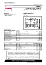
UCD7230 functional diagram.<br />
V IN<br />
V OUT<br />
G SENSE<br />
Communication<br />
(Programming and<br />
Status Reporting)<br />
ADC3<br />
VD25<br />
EAP<br />
EAM<br />
UCD9112<br />
RB0<br />
DPWMA0<br />
AD33<br />
AVSS<br />
DPWMB0<br />
RST RB1/TMRI1<br />
ADC2<br />
1<br />
2<br />
3<br />
4<br />
5<br />
6<br />
7<br />
8<br />
10<br />
V DD<br />
UCD7230<br />
CS+<br />
SRE<br />
IN<br />
3V3<br />
AGND<br />
DLY<br />
ILIM<br />
CLF<br />
AO<br />
CSBIAS<br />
SW<br />
OUT1<br />
BST<br />
PVDD<br />
OUT2<br />
PGND<br />
NEG<br />
POS<br />
20<br />
19<br />
8<br />
7<br />
16<br />
5<br />
4<br />
13<br />
2<br />
1<br />
G SENSE<br />
R NEG<br />
R POS<br />
V OUT<br />
UCD7230 digital converter application.<br />
Texas Instruments <strong>2Q</strong> <strong>2007</strong><br />
<strong>Power</strong> <strong>Management</strong> <strong>Selection</strong> <strong>Guide</strong>
12<br />
➔<br />
Fusion Digital <strong>Power</strong> TM Control Solutions<br />
Digital PWM Controllers<br />
Digital PWM Controllers<br />
UCD9111, UCD9112<br />
Get samples and datasheets at:<br />
www.ti.com/sc/device/UCD9111 or<br />
www.ti.com/sc/device/UCD9112<br />
Differential<br />
Sense Input<br />
Feedback Analog<br />
Conditioning<br />
The UCD9K devices provide full digital power<br />
management capabilities to close multiple<br />
feedback loops in the digital domain and the<br />
integrated resources for supervision, communication,<br />
configuration and monitoring.<br />
Features<br />
• Digital synchronous buck PWM controller<br />
with 175-ps PWM resolution<br />
• Digital control with programmable PID<br />
compensation<br />
•V OUT from 1% to 99% of V IN<br />
• Programmable switching frequency,<br />
capable of up to 2 MHz/phase<br />
• Programmable soft start and soft stop<br />
• Supports pre-biased outputs<br />
• 0.5% internally trimmed 800-mV reference<br />
•V IN from 4.5 to 15.5 V (UCD7230)<br />
• Remote sensing differential amplifier<br />
• <strong>Power</strong> supply monitoring via PMBus<br />
• Single bias supply (3.3-V V DD )<br />
• Intuitive graphical user interface<br />
• Internal thermal sensor<br />
• PMBus support<br />
PWM Output<br />
Digital-Error<br />
Converter<br />
Digital<br />
Compensator<br />
High-Resolution<br />
DPWs<br />
5 Analog Inputs<br />
for Monitoring<br />
Voltage<br />
Current<br />
Temperature<br />
Compensator<br />
Configuration 1<br />
Compensator<br />
Configuration 2<br />
Data Bus<br />
0.5% 800-mV<br />
Reference<br />
0.1% Jitter<br />
Oscillator<br />
Data Flash<br />
CPU Core<br />
PMBus<br />
UART<br />
Watchdog<br />
Graphical User Interface (GUI)<br />
UCD9111/2 provides an intuitive GUI that<br />
simplifies the design and displays the current<br />
conditions of the converter. It also supports<br />
PMBus commands.<br />
Key Function of GUI<br />
• PID coefficients programming<br />
• POL ON/OFF<br />
•V OUT set point<br />
• Converter switching frequency set<br />
• Output voltage soft start and soft stop<br />
• Fault threshold configuration<br />
• Manufacturing information storage<br />
<strong>Selection</strong> <strong>Guide</strong><br />
Device<br />
UCD9111<br />
UCD9112<br />
Description<br />
Single phase<br />
Dual phase<br />
<strong>Power</strong> <strong>Management</strong> <strong>Selection</strong> <strong>Guide</strong> Texas Instruments <strong>2Q</strong> <strong>2007</strong>
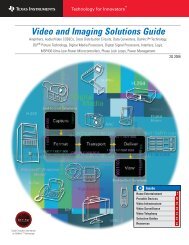
<strong>Power</strong>-Supply Sequencer<br />
UCD9080<br />
Fusion Digital <strong>Power</strong> TM Control Solutions<br />
<strong>Power</strong>-Supply Sequencer<br />
13<br />
➔<br />
Get samples and datasheets at: www.ti.com/sc/device/UCD9080<br />
The UCD9080 power-supply sequencer controls<br />
the power sequencing of up to eight voltage<br />
rails and three independent digital I/Os with<br />
a single device. No external memory or clock<br />
is required, and the device runs from a single<br />
3.3-V supply.<br />
The UCD9080 monitors all the voltage rails<br />
at a sampling rate of 20 kHz with 3.5-mV<br />
resolution. It has a high degree of configurability<br />
to sequence the rails for power up and<br />
power down.<br />
The UCD9080 also includes options such as<br />
resequencing in the event of faults such as<br />
rail failures. Rail sequencing can be based on<br />
timed events or on timed events in conjunction<br />
with other rails achieving regulation. In<br />
addition, each rail is monitored for glitches and<br />
under- and over-voltage threshold violations.<br />
Each rail that the UCD9080 monitors can be<br />
configured to shut down other rails as set in<br />
the configuration screen.<br />
UCD9080 Sequencing Configuration<br />
• Flexible sequencing options including:<br />
• Time-based<br />
• Sequence after another rail achieves<br />
regulation (plus time)<br />
• Sequence after another rail achieves a<br />
certain voltage level<br />
• <strong>Power</strong>-up and power-down sequencing<br />
• Configurable voltage-rail dependencies<br />
Features<br />
• Single-chip design, operates from 3.3-V<br />
supply<br />
• Additional GPIOs with control for device<br />
resets, LED control, etc.<br />
• Under- and over-voltage monitoring<br />
• Fast and flexible shut-down options<br />
through use of interdependency<br />
• Error log and status monitoring provided<br />
through I 2 C interface<br />
• Non-volatile error log storage to Flash<br />
for field debug of critical supply failures<br />
• Configurable sequencing options, over-/<br />
under-voltage thresholds, shut-down<br />
response<br />
• Easy-to-use Windows ® operating<br />
system GUI<br />
RAIL0<br />
RAIL0<br />
RAIL1<br />
RAIL2<br />
RAIL3<br />
RAIL4<br />
RAIL5<br />
RAIL6<br />
RAIL7<br />
POL-1<br />
Low<br />
Dropout<br />
Regulator<br />
VDD_IPM<br />
0<br />
1<br />
2<br />
3<br />
4<br />
5<br />
6<br />
7<br />
RAIL1<br />
POL-2<br />
DC/DC<br />
Converter<br />
A/D Inputs<br />
UCD9080<br />
RAIL2<br />
Enable<br />
Outputs<br />
POL-3<br />
Low<br />
Dropout<br />
Regulator<br />
0<br />
1<br />
2<br />
3<br />
4<br />
5<br />
6<br />
7<br />
EN0<br />
EN1<br />
EN2<br />
EN3<br />
EN4<br />
EN5<br />
EN6<br />
EN7<br />
RAIL3<br />
POL-4<br />
DC/DC<br />
Converter<br />
DC/DC<br />
Converter<br />
Low<br />
Dropout<br />
Regulator<br />
Low<br />
Dropout<br />
Regulator<br />
RAIL4<br />
RAIL5<br />
POL-5<br />
3.3 V<br />
Hard Drive<br />
POL-6<br />
1.8 V DSP<br />
DSP/µC<br />
POL-7<br />
1.5 V<br />
Memory<br />
10 kΩ<br />
To<br />
System<br />
10 kΩ<br />
SDA<br />
SCL<br />
Serial<br />
Interface<br />
V DD<br />
VDD_IPM<br />
Interrupt<br />
Output<br />
INT<br />
INT<br />
To<br />
System<br />
DC/DC<br />
Converter<br />
RAIL6<br />
5.0 V<br />
POL-8<br />
RAIL7<br />
Texas Instruments <strong>2Q</strong> <strong>2007</strong><br />
<strong>Power</strong> <strong>Management</strong> <strong>Selection</strong> <strong>Guide</strong>
14 AC/DC and DC/DC <strong>Power</strong> Supply Products<br />
➔<br />
<strong>Power</strong> Factor Correction (PFC)<br />
Design Factors<br />
Control Method<br />
Average-Current Mode (ACM) —<br />
Optimum control method to achieve PFC and<br />
low harmonic distortion.<br />
Transition Mode (TM) — Simpler inexpensive<br />
control with high peak currents and<br />
filtering requirements.<br />
Interleaved — TM- and ACM-compatible<br />
multiphase, high-power, high-density topology.<br />
Delivers better EMI, smaller magnetics and<br />
reduced ripple currents.<br />
Zero-Voltage-Transition (ZVT) Mode —<br />
A type of soft-switching technique, which<br />
reduces EMI and allows for higher frequency<br />
operations.<br />
Protection<br />
• Soft-start (programmable) provides controlled<br />
start-up.<br />
• Over-current protection (OCP) provides<br />
protection during overload conditions.<br />
• Over-voltage protection (OVP) prevents<br />
output capacitor, switches and load from<br />
overcharge condition.<br />
Performance<br />
• Voltage feed-forward for linearized performance<br />
and faster transient response<br />
over wide line voltage range.<br />
• Multiplier linearity and zero power detect<br />
functions improve light load operation.<br />
• Onboard high output current drive capability<br />
without external MOSFET drivers.<br />
Flexibility<br />
• Ability to work with a wide line<br />
voltage range.<br />
• Different levels of under-voltage lockout<br />
thresholds for self bias and auxiliary bias<br />
applications.<br />
• Ability to synchronize controllers to eliminate<br />
noise issues.<br />
<strong>Power</strong> Level<br />
• IEC requirements are applicable to all<br />
power supplies above 150 W.<br />
• Higher power converters may require zerocurrent-switching<br />
(ZCS) and ZVT-switching<br />
techniques to achieve high efficiencies.<br />
• Some of the simpler control techniques not<br />
usable at high power levels.<br />
Features<br />
From 50 W to 5 kW, TI PFC controllers deliver<br />
EN61000-3-2 compliance.<br />
• Industry standard architecture.<br />
• Deliver PF > 0.993.<br />
• New BiCMOS generation reduces<br />
complexity.<br />
• Optimized PFC/PWM “combo” controllers.<br />
• Superior applications support.<br />
Interleaved PFC<br />
Interleaving is a PFC method that is gaining<br />
popularity in external and embedded-type<br />
power-supply architectures. It is exceptionally<br />
flexible and provides many options such as<br />
passive-component size reductions, smaller<br />
EMI filtering circuits and higher efficiencies.<br />
Line<br />
C OUT<br />
OUT<br />
Another benefit of multiphase interleaving is<br />
that its scalability allows it to address many<br />
different power levels and applications.<br />
Why Interleave<br />
• Input and output ripple current cancellation<br />
• Reduces boost inductor volume<br />
• Reduces output capacitor RMS current<br />
• Reduces the EMI filter size<br />
0.60<br />
Analog and Digital<br />
Interleaved Solutions<br />
from TI<br />
1.0<br />
0.54<br />
0.9<br />
Output Capacitor Current, ICOUT (A)<br />
0.48<br />
0.42<br />
0.36<br />
0.30<br />
0.24<br />
0.18<br />
0.12<br />
0.06<br />
Single-Stage C OUT<br />
RMS Current<br />
Interleaved C OUT<br />
RMS Current<br />
Inductor Ripple Current, Cancelation Factor<br />
0.8<br />
0.7<br />
0.6<br />
0.5<br />
0.4<br />
0.3<br />
0.2<br />
0.1<br />
0<br />
0 0.1 0.2 0.3 0.4 0.5 0.6 0.7 0.8 0.9 1.0<br />
Duty Cycle, D (Θ)<br />
0<br />
0 0.1 0.2 0.3 0.4 0.5 0.6 0.7 0.8 0.9 1.0<br />
Duty Cycle, D (Θ)<br />
<strong>Power</strong> <strong>Management</strong> <strong>Selection</strong> <strong>Guide</strong> Texas Instruments <strong>2Q</strong> <strong>2007</strong>
AC/DC and DC/DC <strong>Power</strong> Supply Products<br />
15<br />
<strong>Selection</strong> <strong>Guide</strong><br />
<strong>Power</strong> Factor Correction (PFC)<br />
Typical Max Start-Up UVLO PWM Prog. PWM<br />
Control <strong>Power</strong> Soft Frequency Current Thresholds Max Duty Freq.<br />
Device Description Method 1 Level Switching 2 (kHz) (mA) (V) Cycle Option OVP Price*<br />
UCC28019 8-Pin PFC Controller ACM 75 W to 600 W — 65 0.01 10.5/9.5 — — — 0.80<br />
UC3852 Transition Mode PFC Controller TM
16<br />
AC/DC and DC/DC <strong>Power</strong> Supply Products<br />
➔<br />
PWM <strong>Power</strong> Supply Controllers<br />
Single-Ended Topologies<br />
Control Method<br />
Voltage Mode — Simple, low-noise<br />
control method for wide input and output<br />
range requirements.<br />
Current Mode — Fast transient response<br />
with built-in current limiting.<br />
Level of Integration<br />
• Integrated soft-start (programmable)<br />
provides predictable start-up.<br />
• Internal leading edge blanking to suppress<br />
switching spike from MOSFET turn-on.<br />
Performance<br />
• Many voltage mode controllers have input<br />
voltage feedforward for instantaneous<br />
response to input line changes.<br />
• Most controllers have onboard high<br />
current drive capability without external<br />
MOSFET drivers.<br />
• Lower start-up current for offline<br />
applications (for BiCMOS products with<br />
UCC prefix).<br />
• Low operating current (for BiCMOS products<br />
with UCC prefix) for light-load efficiency.<br />
• Programmable minimum duty cycle clamp<br />
for light-load efficiency (UCC3581).<br />
Features<br />
• 10-W to 350-W offline and DC/DC<br />
power supplies.<br />
• Single-ended topology power supplies,<br />
buck, boost, flyback and forward.<br />
Double-Ended Topologies<br />
Current Mode — Control technique featuring<br />
fast transient response with inherent<br />
cycle-by-cycle current limiting.<br />
Voltage Mode — Versatile, low-noise<br />
control method for wide duty cycle ranges.<br />
Soft Switching<br />
• Zero Voltage Transition (ZVT) soft switching<br />
techniques minimize power loss at<br />
turn-on.<br />
• Phase shifted, ZVT controllers maximize<br />
efficiency in full-bridge converters.<br />
Protection<br />
• Flexible over-current limiting circuitry provides<br />
programmable fault protection modes.<br />
• Programmable soft-start executes<br />
predictable start-up on initialization and<br />
after faults.<br />
• High speed, cycle-by-cycle current limiting.<br />
• Maximum duty cycle clamp to prevent<br />
transformer saturation.<br />
• Programmable deadtime control to prevent<br />
cross conduction of power switches.<br />
Low- to Medium-<strong>Power</strong> PWM Controllers (25 W – 350 W)<br />
Soft-Switching<br />
(Active-clamp forward,<br />
active-clamp flyback)<br />
UCC3580<br />
V-Mode<br />
Act-Clamp<br />
UCC2891-4<br />
I-Mode<br />
Act-Clamp,<br />
HVStart<br />
UCC2897<br />
Adv. I-Mode<br />
Act-Clamp,<br />
HVStart<br />
Dual Outputs<br />
(Push-pull, half-bridge,<br />
two independent<br />
flybacks and forwards)<br />
UCC38083-6<br />
+Slope Comp.<br />
UCC3808/A<br />
8-Pin P-P<br />
UCC28089<br />
Push-Pull<br />
Oscillator<br />
UC3846<br />
UCC3810<br />
Two Independent<br />
Channels, ≤50% DC<br />
UCC3806<br />
BiCMOS<br />
UC3846<br />
Wide Input Range<br />
Voltage Mode<br />
(Forward, flyback,<br />
boost)<br />
UCC35705/6<br />
4-MHz PWM with<br />
Prog. Max DC<br />
UCC35701/2<br />
High-Level<br />
Protection<br />
UCC2540<br />
Secondary Side<br />
Sync. Buck<br />
General-Purpose<br />
Single-Ended PWM<br />
(Forward, flyback, buck,<br />
boost, SEPIC, Cuk)<br />
UCC38C42-45<br />
BiCMOS<br />
UCC3842A-45A<br />
UC3842-5<br />
UC3842A-5A<br />
UCC3807<br />
Prog. Max DC<br />
UCC3809<br />
Prog. Max DC,<br />
SS, No E/A<br />
UCC3800-5<br />
UCC3813<br />
4/5-V REF , SS, LEB<br />
UCC3884<br />
Freq. Foldback,<br />
VxS Clamp<br />
Green-Mode PWMs and<br />
Off-Line Bias Regulators<br />
(Flyback, forward,<br />
quasi-resonant flyback)<br />
UCC3888/89<br />
Off-Line Bias<br />
Regulators<br />
UCC28600<br />
8-Pin QR Green<br />
Mode Controller<br />
UCC3581<br />
Micropower<br />
PWM<br />
Voltage Mode<br />
Current Mode<br />
Features/Level of Integration<br />
<strong>Power</strong> <strong>Management</strong> <strong>Selection</strong> <strong>Guide</strong> Texas Instruments <strong>2Q</strong> <strong>2007</strong>
AC/DC and DC/DC <strong>Power</strong> Supply Products<br />
17<br />
Medium- to High-<strong>Power</strong> PWM Controllers (>300 W)<br />
PWM <strong>Power</strong> Supply Controllers<br />
➔<br />
Soft-Switching, ZVT, ZVS<br />
(Phase-shifted fullbridge,<br />
resonant,<br />
active-clamp forward)<br />
UC3861-8<br />
Resonant Mode<br />
UCC3580<br />
V-Mode<br />
Act-Clamp<br />
UCC2891-4<br />
I-Mode<br />
Act-Clamp,<br />
HVStart<br />
UCC2897<br />
Adv. I-Mode<br />
Act-Clamp,<br />
HVStart<br />
UC3879<br />
φ-Shift w/o Drivers<br />
UCC3895<br />
Adv. φ-Shift<br />
UC3875-8<br />
φ-Shift w/Drivers<br />
Dual-Complementary<br />
Outputs<br />
(Push-pull, half-bridge,<br />
full-bridge, current-fed/<br />
voltage-fed push-pull)<br />
UC3524A<br />
UC3525A<br />
UC3526A<br />
UCC38083-6<br />
+Slope Comp.<br />
UCC3808/A<br />
8-Pin P-P<br />
UC3846<br />
UC3856<br />
UC3825<br />
UC28025<br />
UC3825A/B<br />
UCC3806<br />
BiCMOS<br />
UC3846<br />
Dual Controllers<br />
(Buck, boost, forward,<br />
interleaved flyback)<br />
UCC3810<br />
Two Independent<br />
Channels, ≤50% DC<br />
UCC28220/1<br />
Interleaved<br />
Fwd/Flyback<br />
Prog. Max DC > 50%<br />
Secondary Side Control,<br />
Post Regulation<br />
(Forward, buck,<br />
synchronous buck)<br />
UCC3839<br />
Avg. I-Mode<br />
UCC3583<br />
SSPR<br />
UCC3580<br />
Sync. Rect.<br />
Control<br />
UCC3960/61<br />
Primary Side<br />
Start-Up<br />
UC3824<br />
UC3849<br />
Avg. I-Mode<br />
w/LS<br />
UCC2540<br />
Sec. Side<br />
Sync Buck<br />
Resonant Mode<br />
Single-Ended Controllers<br />
(Forward)<br />
UC3841<br />
UC3851<br />
UC3823A/B<br />
UC3823<br />
UC3848<br />
Avg. I-Mode<br />
UCC3884<br />
Frequency<br />
Foldback<br />
VxS Clamp<br />
Voltage Mode<br />
Current Mode<br />
Features/Level of Integration<br />
Resources For a complete list of Resources, visit power.ti.com<br />
Part Number Description Price*<br />
Evaluation Modules (EVMs)<br />
UCC28600EVM 120 W Green Mode PS with PFC 49<br />
UCC28600EVM 65 W Green Mode Adapter 49<br />
UCC2891EVM 48-V to 3.3-V Forward Converter with Active Clamp Reset Using the UCC2891 49<br />
UCC35705EVM 48-V to 3.3-V RCD Forward with the UCC35705 49<br />
UCC3895EVM-001 UCC3895EVM Configuring for Direct Control Driven Synchronous Rectifier Applications 99<br />
UCC3809EVM 10-W Flyback Converter Utilizing the UCC3809 49<br />
UCC3889EVM A Dual-Output, Non-Isolated Off-Line <strong>Power</strong> Supply Highlighting the UCC3889 and TPS77401 49<br />
*Suggested resale price in U.S. dollars.<br />
Literature Number<br />
Application Notes<br />
SLUA149<br />
SLUA303<br />
SLUA276<br />
SLUA213<br />
SLUA246<br />
SLUA257<br />
SLUA286<br />
SLUA287<br />
SLUA322<br />
Reference Designs<br />
SLUU135A<br />
SLUA276<br />
SLUA274<br />
SLUA275<br />
SLUU192A<br />
SLUA303<br />
SLUU178<br />
Description<br />
UCC3800/1/2/3/4/5 BiCMOS Current Mode Control ICs<br />
Designing for High Efficiency with the Active Clamp UCC2891 PWM Controller<br />
25-W Forward Converter Design Review<br />
Comparing the UC3842, UCC3802, and UCC3809 Primary Side PWM Controllers<br />
A Comparison Between the BiCMOS UCC3895 Phase Shift Controller and the UC3875<br />
The UCC38C42 Family of High-Speed, BiCMOS Current-Mode PWM Controllers<br />
Low Voltage Feedback in PWM Applications<br />
Control Driven Synchronous Rectifiers in Phase Shifted Full Bridge Converters<br />
Active Clamp Transformer Reset: High Side or Low Side<br />
UCC38083 50-W Push-Pull Converter<br />
UCC38C42 25-W Forward Converter<br />
UCC38C44 12-V Isolated Bias Supply<br />
UCC3895 OUTC/OUTD Asymmetric Duty Cycle Operation<br />
48-V to 3.3-V Forward Converter with Active Clamp Reset Using the UCC2897 PWM Controller<br />
Designing with the UCC2891 Active Clamp Controller<br />
Using the UCC2891 Active Clamp and Reset PWM<br />
Texas Instruments <strong>2Q</strong> <strong>2007</strong><br />
<strong>Power</strong> <strong>Management</strong> <strong>Selection</strong> <strong>Guide</strong>
18<br />
➔<br />
AC/DC and DC/DC <strong>Power</strong> Supply Products<br />
PWM <strong>Power</strong> Supply Controllers<br />
<strong>Selection</strong> <strong>Guide</strong><br />
Control<br />
Method<br />
Topologies<br />
Voltage Mode<br />
Current Mode<br />
Avg. Current Mode<br />
Buck<br />
Boost<br />
Flyback (SEPIC, Cuk)<br />
Fwd (Including 2-Switch Fwd)<br />
Forward (D > 50%)<br />
Interleaved Fwd/Flyback/Boost<br />
Act-Clamp Fwd/Flyback<br />
Push-Pull<br />
I-Fed/V-Fed Push-Pull<br />
Half-Bridge<br />
Full-Bridge<br />
Φ-Shifted FB<br />
(Device parameters continued on next page)<br />
Typical<br />
<strong>Power</strong> Maximum Supply 110-V UVLO:<br />
Level Practical Start-Up Operating Voltage Start-Up On/Off<br />
Device (W) Frequency Current Current (V) Circuit (V)<br />
Green Mode Controllers and Offline Bias Regulators<br />
UCC3581 10 to 200 ✔ ✔ ✔ ✔ ✔ 100 kHz 85 µA 300 µA 6.8 to 15 — 7.3/6.8<br />
UCC28600 50 to 150 ✔ ✔ 130 kHz 25 µA 50 mA 30 — 13/8<br />
UCC3888/89
AC/DC and DC/DC <strong>Power</strong> Supply Products<br />
PWM <strong>Power</strong> Supply Controllers<br />
19<br />
➔<br />
(Device parameters continued from previous page)<br />
Available<br />
Packages<br />
Max<br />
V REF Duty Shut- Voltage Output Drive Leading<br />
V REF Tol. Cycle Soft down Feed- (Sink/Source) Slope Sync Edge<br />
Device (V) (%) (%) Start E/A Pin forward (A) Comp Pin Blanking Price*<br />
Green Mode Controllers and Offline Bias Regulators<br />
UCC3581 4 1.5 Prog. ✔ — ✔ — 1/1 — ✔ — 14 14 1.00<br />
UCC28600 — — 99 ✔ — — — 1/0.75 — — — 8 0.49<br />
UCC3888/89 2.5 3 5.5 ✔ — — ✔ 0.2/0.15 — — — 8 8 0.59<br />
General-Purpose Single-Ended Controllers<br />
TL3842 5 2 100 — ✔ — — 1/1 — — — 8/14 8 0.40<br />
TL3842B 5 2 100 — ✔ — — 1/1 — — — 8/14 8 0.54<br />
TL3843 5 2 100 — ✔ — — 1/1 — — — 8/14 8 0.40<br />
TL3843B 5 2 100 — ✔ — — 1/1 — — — 8/14 8 0.54<br />
TL3844 5 2 50 — ✔ — — 1/1 — — — 8/14 8 0.40<br />
TL3844B 5 2 50 — ✔ — — 1/1 — — — 8/14 8 0.54<br />
TL3845 5 2 50 — ✔ — — 1/1 — — — 8/14 8 0.40<br />
TL3845B 5 2 50 — ✔ — — 1/1 — — — 8/14 8 0.54<br />
UC28023 5.1 1 Prog. ✔ ✔ — — 1.5/1.5 — ✔ — 16 16 1.35<br />
UC3823 5.1 1 Prog. ✔ ✔ — ✔ 1.5/1.5 — ✔ — 16 20 16 1.60<br />
UC3823A/B 5.1 1 Prog. ✔ ✔ — ✔ 2/2 — ✔ — 16 20 16 4.90<br />
UC3842/A 5 1.5 100 — ✔ — — 1/1 — — — 8/14 8 0.80<br />
UC3843 5 1.5 100 — ✔ — — 1/1 — — — 8/14 8 0.80<br />
UC3843A 5 1.5 100 — ✔ — — 1/1 — — — 8/14 8 0.80<br />
UC3844/A 5 1.5 50 — ✔ — — 1/1 — — — 8/14 8 0.80<br />
UC3845 5 1.5 50 — ✔ — — 1/1 — — — 8/14 8 0.80<br />
UC3845A 5 1.5 50 — ✔ — — 1/1 — — — 8/14 8 0.80<br />
UC3849 5 2 Prog ✔ ✔ — — 0.3/0.3 — — ✔ 24 28 24 3.05<br />
UCC35705 — — 93 — — — ✔ 0.1/0.1 N/A — — 8 8 8 0.75<br />
UCC35706 — — 93 — — — ✔ 0.1/0.1 N/A — — 8 8 8 0.75<br />
UCC3800 5 1.5 100 ✔ ✔ — — 1/1 — — 100 ns 8 8 8 1.35<br />
UCC3801 5 1.5 50 ✔ ✔ — — 1/1 — — 100 ns 8 8 8 1.35<br />
UCC3802 5 1.5 100 ✔ ✔ — — 1/1 — — 100 ns 8 8 8 1.35<br />
UCC3803 4 1.5 100 ✔ ✔ — — 1/1 — — 100 ns 8 8 8 1.35<br />
UCC3804 5 1.5 50 ✔ ✔ — — 1/1 — — 100 ns 8 8 8 1.35<br />
UCC3805 4 1.5 50 ✔ ✔ — — 1/1 — — 100 ns 8 8 8 1.35<br />
UCC3807-1 2 (Int) — Prog. ✔ ✔ — — 1/1 — — 100 ns 8 8 1.50<br />
UCC3807-2 2 (Int) — Prog. ✔ ✔ — — 1/1 — — 100 ns 8 8 1.50<br />
UCC3807-3 2 (Int) — Prog. ✔ ✔ — — 1/1 — — 100 ns 8 8 1.50<br />
UCC3809-1 5 5 90 ✔ — ✔ — 0.8/0.4 — — — 8 8 8 8 0.85<br />
UCC3809-2 5 5 90 ✔ — ✔ — 0.8/0.4 — — — 8 8 8 8 0.85<br />
UCC3813-0 5 2 100 ✔ ✔ — — 1/1 — — 100 ns 8 8 8 0.80<br />
UCC3813-1 5 2 50 ✔ ✔ — — 1/1 — — 100 ns 8 8 8 0.80<br />
UCC3813-2 5 2 100 ✔ ✔ — — 1/1 — — 100 ns 8 8 8 0.80<br />
UCC3813-3 4 2 100 ✔ ✔ — — 1/1 — — 100 ns 8 8 8 0.80<br />
UCC3813-4 5 2 50 ✔ ✔ — — 1/1 — — 100 ns 8 8 8 0.80<br />
UCC3813-5 4 2 50 ✔ ✔ — — 1/1 — — 100 ns 8 8 8 0.80<br />
UCC3884 5 2.5 100 ✔ ✔ — ✔ 1/0.5 — — — 16 16 1.60<br />
UCC38C40 5 2 100 — ✔ — — 1/1 — — — 8 8 8 0.95<br />
UCC38C41 5 2 50 — ✔ — — 1/1 — — — 8 8 8 0.95<br />
UCC38C42 5 2 100 — ✔ — — 1/1 — — — 8 8 8 0.95<br />
*Suggested resale price in U.S. dollars in quantities of 1,000.<br />
MSOP<br />
SSOP<br />
TSSOP<br />
HTSSOP-<strong>Power</strong>PAD<br />
SOIC<br />
SOIC-W (300 mil)<br />
SOIC-W <strong>Power</strong><br />
PLCC<br />
DIL (PDIP)<br />
New devices are listed in bold red.<br />
Texas Instruments <strong>2Q</strong> <strong>2007</strong><br />
<strong>Power</strong> <strong>Management</strong> <strong>Selection</strong> <strong>Guide</strong>
20<br />
➔<br />
AC/DC and DC/DC <strong>Power</strong> Supply Products<br />
PWM <strong>Power</strong> Supply Controllers<br />
<strong>Selection</strong> <strong>Guide</strong> (Continued)<br />
Control<br />
Method<br />
Topologies<br />
(Device parameters continued on next page)<br />
Typical<br />
<strong>Power</strong> Maximum Supply 110-V UVLO:<br />
Level Practical Start-Up Operating Voltage Start-Up On/Off<br />
Device (W) Frequency Current Current (V) Circuit (V)<br />
General-Purpose Single-Ended Controllers (Continued)<br />
UCC38C43 10 to 250 ✔ ✔ ✔ ✔ ✔ ✔ 1 MHz 50 µA 2.3 mA 7.6 to 20 — 8.4/7.6<br />
UCC38C44 10 to 250 ✔ ✔ ✔ ✔ ✔ ✔ 1 MHz 50 µA 2.3 mA 9 to 20 — 14.5/9<br />
UCC38C45 10 to 250 ✔ ✔ ✔ ✔ ✔ ✔ 1 MHz 50 µA 2.3 mA 7.6 to 20 — 8.4/7.6<br />
Wide-Input Range Voltage Mode Controllers<br />
UCC3570 25 to 250 ✔ ✔ ✔ ✔ 500 kHz 85 µA 1 mA 9.0 to 15 — 13.0/9<br />
UCC35701 25 to 250 ✔ ✔ ✔ ✔ 700 kHz 130 µA 750 µA 9.0 to 15 — 13.0/9<br />
UCC35702 25 to 250 ✔ ✔ ✔ ✔ 700 kHz 130 µA 750 µA 8.8 to 15 — 9.6/8.8<br />
UCC35705 25 to 250 ✔ ✔ ✔ ✔ ✔ 4 MHz 50 µA 2.5 mA 8.2 to 15 — 8.8/8.2<br />
UCC35706 25 to 250 ✔ ✔ ✔ ✔ ✔ 4 MHz 50 µA 2.5 mA 8.0 to 15 — 12/8<br />
Dual Output Controllers<br />
TL494 50 to 500 ✔ ✔ ✔ ✔ ✔ ✔ ✔ ✔ ✔ ✔ 300 kHz — 7.5 mA 7 to 40 — —<br />
TL594 50 to 500 ✔ ✔ ✔ ✔ ✔ ✔ ✔ ✔ ✔ ✔ 300 kHz — 12.4 mA 7 to 40 — 6.1/6<br />
TL598 50 to 500 ✔ ✔ ✔ ✔ ✔ ✔ ✔ ✔ ✔ ✔ 300 kHz — 15 mA 7 to 40 — 6.1/6<br />
SG3524 50 to 500 ✔ ✔ ✔ ✔ 450 kHz — — 8 to 40 — —<br />
UC28025 50 to 750 ✔ ✔ ✔ ✔ ✔ 1 MHz 1.1 mA 22 mA 9 to 30 — 9.2/8.4<br />
UC3524 50 to 500 ✔ ✔ ✔ ✔ 250 kHz — — 8 to 40 — —<br />
UC3524A 50 to 500 ✔ ✔ ✔ ✔ 250 kHz 4 mA 5 mA 8 to 40 — 7.5/7<br />
UC3525A/B 50 to 500 ✔ ✔ ✔ ✔ 250 kHz — 14 mA 8 to 40 — 7.0/7.0<br />
UC3526A 50 to 500 ✔ ✔ ✔ ✔ 250 kHz — 14 mA 8 to 35 — —<br />
UC3825 50 to 750 ✔ ✔ ✔ ✔ ✔ 1 MHz 1.1 mA 22 mA 9 to 30 — 9.2/8.4<br />
UC3825A/B 50 to 750 ✔ ✔ ✔ ✔ ✔ 1 MHz 100 µA 28 mA 9 to 22 — 16/10/9.2/8.4<br />
UC3827-1/-2 50 to 500 ✔ ✔ 450 kHz 1000 µA 32 mA 8.4 to 20 — 9/8.4<br />
UC3846 50 to 750 ✔ ✔ ✔ ✔ ✔ 500 kHz 1.5 mA 17 mA 8 to 40 — 7.7/7<br />
UC3856 50 to 750 ✔ ✔ ✔ ✔ ✔ 1 MHz 1.5 mA 17 mA 8 to 40 — 7.7/7<br />
UCC28089 25 to 250 ✔ ✔ ✔ ✔ 500 kHz 130 µA 1.4 mA 8 to 15 — 10.5/8.0<br />
UCC28220 50 to 800 ✔ ✔ 1 MHz/ch. 200 µA 3 mA 8 to 14.5 — 10/8<br />
UCC28221 50 to 800 ✔ ✔ 1 MHz/ch. 500 µA 3 mA 8 to 14.5 ✔ 13/8<br />
UCC3806 50 to 750 ✔ ✔ ✔ ✔ ✔ 350 kHz 100 µA 1.4 mA 7 to 15 — 7.5/6.7<br />
UCC3808-1/-2/A-1/A-2 50 to 500 ✔ ✔ ✔ ✔ 1 MHz 130 µA 1 mA 4.3 to 15 — 12.5/8.3/4.3/4.1<br />
UCC38083/4/5/6 50 to 500 ✔ ✔ ✔ ✔ 1 MHz 130 µA 20 mA 8.3 to 15 — 12.5/8.3<br />
UCC3810 50 to 500 ✔ ✔ ✔ ✔ ✔ ✔ ✔ 1 MHz 150 µA 2 mA 8.3 to 11 — 11.3/8.3<br />
Soft-Switching, ZVT and ZVS Controllers<br />
UC3875-8 200 W to 2 kW ✔ ✔ ✔ ✔ ✔ 1+ MHz 150 µA 45 mA 10.7 to 20 — 10.7/9.3/15/9<br />
UC3879 200 W to 2 kW ✔ ✔ ✔ 500 kHz 150 µA 27 mA 11 to 20 — 15.2/9/10.7/9<br />
UCC2891/2/3/4 75 to 600 ✔ ✔ ✔ 1 MHz 300 µA 2 mA 8.5 to 14.5 ✔ 1 13/8.0<br />
UCC2897 75 to 600 ✔ ✔ ✔ 1 MHz 300 µA 2 mA 8.5 to 14.5 ✔ 13/8.0<br />
UCC3580-1/-2/-3/-4 50 to 500 ✔ ✔ ✔ 500 kHz 100 µA 1.5 mA 7 to 15 — 15/8.5/9.8/5<br />
UCC3895 200 W to 2 kW ✔ ✔ ✔ ✔ 1 MHz 150 µA 5 mA 11 to 17 — 11/9<br />
Secondary-Side, Post Regulation<br />
UC3824 50 to 250 ✔ ✔ 1 MHz 1.1 mA 22 mA 9 to 30 — 9.2/8.4<br />
UCC2540 50 to 500 ✔ ✔ 1000 kHz — 12 mA 2.8 to 36 — —<br />
UCC3580-1/-2/-3/-4 50 to 500 ✔ ✔ 500 kHz 100 µA 1.5 mA 7 to 15 — 15/8.5/9.8/5<br />
UCC3583 50 to 500 500 kHz 100 µA 3 mA 8.5 to 15 — 9/8.4<br />
UCC3960 25 to 250 ✔ ✔ ✔ ✔ ✔ 400 kHz 150 µA 2.3 mA 8.0 to 19 — 9.5/10.5<br />
UCC3961 25 to 250 ✔ ✔ ✔ ✔ ✔ 400 kHz 150 µA 2.3 mA 8.0 to 19 — 9.5/10.5<br />
1 UCC2891 and UCC2893.<br />
Voltage Mode<br />
Current Mode<br />
Avg. Current Mode<br />
Buck<br />
Boost<br />
Flyback (SEPIC, Cuk)<br />
Fwd (Including 2-Switch Fwd)<br />
Forward (D > 50%)<br />
Interleaved Fwd/Flyback/Boost<br />
Act-Clamp Fwd/Flyback<br />
Push-Pull<br />
I-Fed/V-Fed Push-Pull<br />
Half-Bridge<br />
Full-Bridge<br />
Φ-Shifted FB<br />
<strong>Power</strong> <strong>Management</strong> <strong>Selection</strong> <strong>Guide</strong> Texas Instruments <strong>2Q</strong> <strong>2007</strong>
AC/DC and DC/DC <strong>Power</strong> Supply Products<br />
PWM <strong>Power</strong> Supply Controllers<br />
21<br />
➔<br />
(Device parameters continued from previous page)<br />
Available<br />
Packages<br />
Max<br />
V REF Duty Shut- Voltage Output Drive Leading<br />
V REF Tol. Cycle Soft down Feed- (Sink/Source) Slope Sync Edge<br />
Device (V) (%) (%) Start E/A Pin forward (A) Comp Pin Blanking Price*<br />
General-Purpose Single-Ended Controllers (Continued)<br />
UCC38C43 5 2 100 — ✔ — — 1/1 — — — 8 8 8 0.95<br />
UCC38C44 5 2 50 — ✔ — — 1/1 — — — 8 8 8 0.95<br />
UCC38C45 5 2 50 — ✔ — — 1/1 — — — 8 8 8 0.95<br />
Wide-Input Range Voltage Mode Controllers<br />
UCC3570 5 2 Prog. ✔ — ✔ ✔ 1.2/1.2 N/A — N/A 14 14 3.45<br />
UCC35701 5 1.5 VS Clamp ✔ — ✔ ✔ 1.2/1.2 N/A ✔ N/A 14 14 14 2.95<br />
UCC35702 5 1.5 VS Clamp ✔ — ✔ ✔ 1.2/1.2 N/A ✔ N/A 14 14 14 2.95<br />
UCC35705 — — 93 — — — ✔ 0.1/0.1 N/A — N/A 8 8 8 0.75<br />
UCC35706 — — 93 — — — ✔ 0.1/0.1 N/A — N/A 8 8 8 0.75<br />
Dual Output Controllers<br />
TL494 5 5 45 — ✔ — — 0.2/0.2 N/A ✔ — 16 16 16 0.23<br />
TL594 5 1 45 — ✔ — — 0.2/0.2 N/A ✔ — 16 16 16 0.38<br />
TL598 5 1 45 — ✔ — — 0.2/0.2 N/A ✔ — 16 16 0.81<br />
SG3524 5 4 45 — ✔ ✔ — 0.1/0.1 N/A ✔ — 16 16 0.50<br />
UC28025 5.1 1 Prog. ✔ ✔ — — 1.5/1.5 — ✔ — 16 16 1.35<br />
UC3524 5 4 45 — ✔ ✔ — 0.1/0.1 N/A ✔ — 16 16 0.85<br />
UC3524A 5 2 Prog. ✔ ✔ ✔ — 0.2/0.2 — ✔ — 16 16 1.70<br />
UC3525A/B 5 2 Prog. ✔ ✔ ✔ — 0.2/0.2 — ✔ — 16 20 16 1.05<br />
UC3526A 5.1 1.3 Prog. ✔ ✔ ✔ — 0.2/0.2 — ✔ — 16 20 16 1.05<br />
UC3825 5.1 1 Prog. ✔ ✔ — — 1.5/1.5 — ✔ — 16 20 16 1.60<br />
UC3825A/B 5.1 1.5 Prog. ✔ ✔ — — 2/2 — ✔ — 16 20 16 2.65<br />
UC3827-1/-2 5 4 — ✔ ✔ — — 1/0.8 — ✔ — 24 28 24 3.50<br />
UC3846 5 2 Prog. ✔ ✔ — — 0.5/0.5 — ✔ — 16 20 16 1.60<br />
UC3856 5 2 Prog. ✔ ✔ — — 0.5/0.5 — ✔ — 16 20 16 1.70<br />
UCC28089 — — 50 ✔ — — — 0.5/1.0 — ✔ — 8 0.65<br />
UCC28220 3.3 4.5 Prog. ✔ — — — 0.01/0.01 Prog. — — 16 16 1.60<br />
UCC28221 3.3 4.5 Prog. ✔ — — — 0.01/0.01 Prog. — — 20 16 1.65<br />
UCC3806 5.1 3 Prog. ✔ ✔ ✔ — 0.5/0.5 — ✔ — 16 16 16 16 20 16 4.10<br />
UCC3808-1/-2/A-1/A-2 — — Prog. ✔ ✔ — — 1.0/0.5 — ✔ — 8 8 8 1.30<br />
UCC38083/4/5/6 5 2 50 ✔ — — — 1.0/0.5 Prog. — — 8 8 8 1.10<br />
UCC3810 5 2 50 — ✔ ✔ — 1/1 — ✔ — 16 16 1.85<br />
Soft-Switching, ZVT and ZVS Controllers<br />
UC3875-8 5 2 Prog. ✔ ✔ — — Four @ 2/2 — ✔ — 20 28 20 4.85<br />
UC3879 5 2.5 Prog. ✔ ✔ — — Four @ 0.1/0.1 — ✔ — 20 28 20 3.70<br />
UCC2891/2/3/4 5 1 Prog. ✔ — ✔ — 2/2, 2/2 Prog. ✔ — 16 16 1.50<br />
UCC2897 5 1 Prog. ✔ — ✔ — 2/2, 2/2 Prog. ✔ — 20 16 1.50<br />
UCC3580-1/-2/-3/-4 5 1 Prog. ✔ ✔ ✔ ✔ 0.5/1, 0.3/0.3 — — — 16 16 2.40<br />
UCC3895 5 3 Prog. ✔ ✔ ✔ — Four @ 0.1/0.1 — ✔ — 20 20 20 4.35<br />
Secondary-Side, Post Regulation<br />
UC3824 5.1 1 Prog. ✔ ✔ — — 1.5/1.5 — ✔ — 16 16 4.55<br />
UCC2540 3.3 0.6 100 ✔ ✔ — — 3/3 — ✔ — 20 1.85<br />
UCC3580-1/-2/-3/-4 5 1 Prog. ✔ ✔ ✔ ✔ 0.5/1, 0.3/0.3 — — — 16 16 1.90<br />
UCC3583 5 1.5 9.5 ✔ ✔ — — 0.5/1.5 — ✔ — 14 20 14 1.75<br />
UCC3960 — — 72 ✔ — — — 0.75/1.5 — — — 8 8 0.95<br />
UCC3961 — — 72 ✔ — — — 0.75/1.5 — — — 14 14 1.05<br />
*Suggested resale price in U.S. dollars in quantities of 1,000.<br />
MSOP<br />
SSOP<br />
TSSOP<br />
HTSSOP-<strong>Power</strong>PAD<br />
SOIC<br />
SOIC-W (300 mil)<br />
SOIC-W <strong>Power</strong><br />
PLCC<br />
DIL (PDIP)<br />
Texas Instruments <strong>2Q</strong> <strong>2007</strong><br />
<strong>Power</strong> <strong>Management</strong> <strong>Selection</strong> <strong>Guide</strong>
22<br />
AC/DC and DC/DC <strong>Power</strong> Supply Products<br />
➔<br />
MOSFET Drivers<br />
Design Factors<br />
Supply Voltage Range — With internal<br />
voltage regulators, MOSFET drivers can<br />
operate over a wide input voltage range,<br />
making them flexible for many applications.<br />
Number of Outputs — Single and dual<br />
drivers are available to complement DC/DC<br />
switching and motor control applications.<br />
Output Configuration — Inverting, noninverting,<br />
AND and NAND configurations<br />
are available.<br />
TrueDrive Output Stage —- Used in TI<br />
high-current gate drivers and controllers, the<br />
TrueDrive output architecture is constructed<br />
of bipolar and CMOS transistors in parallel.<br />
TrueDrive technology delivers high current<br />
where it is needed most—at the MOSFET<br />
Miller plateau region thresholds—and provides<br />
switching efficiency gains.<br />
Predictive Gate Drive Technology —<br />
This patented TI technology is a digital control<br />
technique to control delay times in highefficiency,<br />
low-output-voltage synchronous<br />
buck converters. See our application notes<br />
(SLUA281 and SLUA285) on Predictive Gate<br />
Drive for a complete description.<br />
120-V Dual MOSFET High-Side, Low-Side Drivers<br />
UCC27200, UCC27201<br />
Get samples and datasheets at: www.ti.com/sc/device/UCC27200 or<br />
www.ti.com/sc/device/UCC27201<br />
Key Features<br />
• Drives two N-channel MOSFETs in high-side, low-side configuration<br />
• Boot voltage absolute maximum: 120 V<br />
• On-chip 0.65-V VF, 0.6-Ω RD bootstrap diode<br />
• Up to 1-MHz operation<br />
• 20-ns typical propagation delay<br />
• 2.5-A sink, 2-A source output currents<br />
• 10-ns rise and 8-ns fall time with 1000-pF load<br />
• 2-ns typical delay matching<br />
• Packaging: SOIC-8, <strong>Power</strong>PAD SOIC-8 and space-saving DFN (all lead-free packages)<br />
HI<br />
V DD<br />
UCC27200/01 block diagram.<br />
LI<br />
5<br />
1<br />
6<br />
UVLO<br />
UVLO<br />
Level<br />
Shift<br />
2 HB<br />
3<br />
HO<br />
4<br />
HS<br />
8<br />
LO<br />
7<br />
V SS<br />
MOSFET Drivers Family of Products<br />
9.0<br />
6.0<br />
UCC37321/2<br />
UC3710<br />
(D) Dual<br />
(R) Internal Regulator<br />
Synchronous Buck Drivers<br />
Peak Output Current (A)<br />
4.0<br />
3.0<br />
2.0<br />
1.0<br />
UCC37323/4/5 (D),<br />
UCC27423/4/5 (D)<br />
TPS28225 (D)<br />
UCC27221/2/3 (D) (R)<br />
TPS2830/1/2/3 (D),<br />
TPS2834/5/6/7 (D)<br />
UCC27200 (D),<br />
UCC27201 (D)<br />
TPS2813/14/15 (D),<br />
TPS2828/29<br />
TPS2838/39/48/49 (D)<br />
UCD7100, UCD7201 (D), UCD7230 (D)<br />
UC3708 (D)<br />
TPS2811/12 (D) (R), TPS2816/17/18/19 (R)<br />
UC3706 (D), UC3709 (D), UC3707 (D), UC3705<br />
UC3714 (D), UC3715 (D)<br />
General-Purpose Drivers<br />
0 5 10 15 20 25 30 35 40<br />
Supply Voltage Range (Vcc)<br />
<strong>Power</strong> <strong>Management</strong> <strong>Selection</strong> <strong>Guide</strong> Texas Instruments <strong>2Q</strong> <strong>2007</strong>
AC/DC and DC/DC <strong>Power</strong> Supply Products<br />
23<br />
<strong>Selection</strong> <strong>Guide</strong><br />
MOSFET Drivers<br />
Peak I OUT Rise/Fall V CC Prop Dead<br />
No. of Output Output Source/Sink Time Range Delay Input Time Protection Internal<br />
Device Outputs Configuration Type 1 (A) (ns) (V) (ns) Threshold Enable Control Features 2 Regulator Price*<br />
General-Purpose Low-Side Drivers<br />
TPS2811 2 Inverting TrueDrive 2.0/2.0 25/25 4 to 40 40 CMOS — — — ✔ 0.90<br />
TPS2812 2 Non-inverting TrueDrive 2.0/2.0 25/25 4 to 40 40 CMOS — — — ✔ 0.90<br />
TPS2813 2 See Note 3 TrueDrive 2.0/2.0 25/25 4 to 14 40 CMOS — — — ✔ 0.90<br />
TPS2814 2 Dual 2-input AND; TrueDrive 2.0/2.0 25/25 4 to 14 40 CMOS — — — — 0.90<br />
one inverting<br />
TPS2815 2 2-input NAND TrueDrive 2.0/2.0 25/25 4 to 14 40 CMOS ✔ N/A — — 0.90<br />
TPS2816 1 Inverting TrueDrive 2.0/2.0 25/25 4 to 40 40 CMOS — N/A — ✔ 0.65<br />
TPS2817 1 Non-inverting TrueDrive 2.0/2.0 25/25 4 to 40 40 CMOS — N/A — ✔ 0.65<br />
TPS2818 1 Inverting TrueDrive 2.0/2.0 25/25 4 to 40 40 CMOS — N/A — ✔ 0.65<br />
TPS2819 1 Non-inverting TrueDrive 2.0/2.0 25/25 4 to 40 40 CMOS — N/A — ✔ 0.65<br />
TPS2828 1 Inverting TrueDrive 2.0/2.0 25/25 4 to 14 40 CMOS — N/A — — 0.60<br />
TPS2829 1 Non-inverting TrueDrive 2.0/2.0 25/25 4 to 14 40 CMOS — N/A — — 0.60<br />
UC3714 2 Non-inverting Bipolar 0.5/1.0 30/25 7 to 20 50 TTL/PWM ✔ Adj. — — 0.95<br />
UC3715 2 See Note 3 Bipolar 1.0/2.0 30/25 7 to 20 50 TTL/PWM ✔ Adj. — — 0.90<br />
UCC27323 2 Inverting TrueDrive 4.0/4.0 25/25 4 to 15 35 TTL/CMOS — — — — 0.80<br />
UCC27324 2 Non-inverting TrueDrive 4.0/4.0 25/25 4 to 15 35 TTL/CMOS — — — — 0.80<br />
UCC27325 2 See Note 3 TrueDrive 4.0/4.0 25/25 4 to 15 35 TTL/CMOS — — — — 0.80<br />
UCC27423 2 Inverting TrueDrive 4.0/4.0 25/25 4 to 15 35 TTL/CMOS ✔ — — — 0.85<br />
UCC27424 2 Non-inverting TrueDrive 4.0/4.0 25/25 4 to 15 35 TTL/CMOS ✔ — — — 0.85<br />
UCC27425 2 See Note 3 TrueDrive 4.0/4.0 25/25 4 to 15 35 TTL/CMOS ✔ — — — 0.85<br />
UCC37321 1 Inverting TrueDrive 9/9 20/20 4 to 15 30 TTL/CMOS ✔ — — — 0.99<br />
UCC37322 1 Non-inverting TrueDrive 9/9 20/20 4 to 15 30 TTL/CMOS ✔ — — — 0.99<br />
UCD7100PWP 1 Uncommitted/ TrueDrive 4/4 10/10 4.5 to 16 20 CMOS/TTL — Adaptive — — 0.99<br />
Non-inverting<br />
UCD7201PWP 2 Uncommitted/ TrueDrive 4/4 10/10 4.5 to 16 20 CMOS/TTL — Adaptive — — 1.20<br />
Non-inverting<br />
Synchronous Buck Drivers<br />
TPS28225 2 Non-inverting CMOS 2.0/4.0 10/10 4.5 to 8.8 14 TTL/CMOS ✔ Adaptive UVLO — 0.60<br />
TPS28226 2 Non-inverting CMOS 2.0/4.0 10/10 4.5 to 8.8 14 TTL/CMOS ✔ Adaptive UVLO — 0.60<br />
TPS2830 2 Non-inverting TrueDrive 2.4/2.4 50/50 4.5 to 15 75 CMOS ✔ Adaptive OVPC — 1.05<br />
TPS2831 2 Inverting TrueDrive 2.4/2.4 50/50 4.5 to 15 75 CMOS ✔ Adaptive OVPC — 1.05<br />
TPS2832 2 Non-inverting TrueDrive 2.4/2.4 50/50 4.5 to 15 75 CMOS — Adaptive — — 1.00<br />
TPS2833 2 Inverting TrueDrive 2.4/2.4 50/50 4.5 to 15 75 CMOS — Adaptive — — 1.00<br />
TPS2834 2 Non-inverting TrueDrive 2.4/2.4 30/30 4.5 to 15 70 TTL ✔ Adaptive OVPC — 1.05<br />
TPS2835 2 Inverting TrueDrive 2.4/2.4 30/30 4.5 to 15 70 TTL ✔ Adaptive OVPC — 1.05<br />
TPS2836 2 Non-inverting TrueDrive 2.4/2.4 30/30 4.5 to 15 70 TTL — Adaptive — — 1.25<br />
TPS2837 2 Inverting TrueDrive 2.4/2.4 30/30 4.5 to 15 70 TTL — Adaptive — — 1.25<br />
TPS2838 2 Non-inverting TrueDrive 4/4 120 10 to 15 40 TTL ✔ Adaptive — ✔ 1.30<br />
TPS2839 2 Inverting TrueDrive 4/4 120 10 to 15 40 TTL ✔ Adaptive — ✔ 1.30<br />
TPS2848 2 Non-inverting TrueDrive 4/4 120 10 to 15 20 TTL ✔ Adaptive — ✔ 1.25<br />
TPS2849 2 Inverting TrueDrive 4/4 120 10 to 15 20 TTL ✔ Adaptive — ✔ 1.25<br />
UCC27221 2 Inverting TrueDrive 3.3/3.3 20/20 3.7 to 20 82/103 TTL — PGD 4 — ✔ 1.35<br />
UCC27222 2 Non-inverting TrueDrive 3.3/3.3 20/20 3.7 to 20 82/103 TTL — PGD 4 — ✔ 1.35<br />
UCC27223 2 Non-inverting TrueDrive 3.3/3.3 25/35 4.15 to 20 82/103 TTL ✔ PGD 4 — ✔ 1.35<br />
High-Side Low-Side Drivers—Sync Buck, Half Bridge, Full Bridge Boot (V)<br />
UCD7230 2 Non-inverting CMOS 4/4 10/10 to 36 25 CMOS/TTL — Adaptive Adjustable — 0.80<br />
UCC27200 2 Non-inverting TrueDrive 3/3 10/8 to 110 20 CMOS — N/A UVLO — 1.30<br />
UCC27201 2 Non-inverting TrueDrive 3/3 10/8 to 110 20 TTL — N/A UVLO — 1.30<br />
1 Output type: TrueDrive is the hybrid bipolar/CMOS output architecture for 3 One inverting, one non-inverting. New devices are listed in bold red.<br />
improved current drive capability at low voltages (at Miller threshold). 4 Predictive Gate Drive. Preview devices are listed in bold blue.<br />
2 OCP = over-current protection, OVPC = over-voltage protection crowbar. *Suggested resale price in U.S. dollars in quantities of 1,000.<br />
➔<br />
Texas Instruments <strong>2Q</strong> <strong>2007</strong><br />
<strong>Power</strong> <strong>Management</strong> <strong>Selection</strong> <strong>Guide</strong>
24<br />
AC/DC and DC/DC <strong>Power</strong> Supply Products<br />
➔<br />
Loadshare Controllers<br />
Design Factors<br />
Current Sensing — The power supply output<br />
current can be sensed in either the high<br />
or low side of the output being loadshared.<br />
Two controllers (UC3907, UCC39002) can be<br />
used in either arrangement; however, the<br />
UC3902 is for dedicated low-side (ground<br />
referenced) current sensing.<br />
Single or Differential Current Sensing —<br />
Optimal results can be obtained using a<br />
differential current-sense technique in both<br />
high- and low-side applications. The singleended<br />
configuration reduces pin count for<br />
dedicated, ground-referenced applications.<br />
Single or Differential Share Bus —<br />
Depending on the amount of noise in any<br />
specific application, designers can choose to<br />
use either a single-ended or differential type<br />
common loadshare bus command among the<br />
modules being shared. True differential mode<br />
offers the most noise immunity, but the singleended<br />
variety can also yield excellent results<br />
when designed with a high amplitude loadshare<br />
signal.<br />
Master/Slave Status — One loadshare<br />
controller (the UC3907) features a master/<br />
slave output signal for interfacing with<br />
other power supplies and end-system<br />
diagnostic circuits.<br />
Hot-Swap/Hot-Plug — The new UCC39002<br />
features the ability to hot-swap or hot-plug<br />
modular power supplies without disturbing<br />
the loadshare bus “share” command.<br />
Current Loop Compensation — Each of<br />
these loadshare controllers offers designers<br />
the ability to compensate the current share<br />
loop as required by the system or individual<br />
power supplies.<br />
Intel SSI Compliance — The UCC39002<br />
meets the Intel SSI spec requirements of<br />
1) single connection between parallel modules<br />
and 2) scalable loadshare voltage independent<br />
of the CS resistor.<br />
Advanced 8-Pin Loadshare Controller<br />
UCC39002<br />
Get samples, datasheets, evaluation modules and app reports at: www.ti.com/sc/device/UCC39002<br />
Key Features<br />
• High accuracy, better than 1% current share error at full load<br />
• High-side or low-side (GND reference) current-sense capability<br />
• Ultra-low offset current-sense amplifier using post package trimming<br />
V+<br />
S+<br />
<strong>Power</strong> Supply<br />
with<br />
Remote Sense<br />
S–<br />
V–<br />
<strong>Selection</strong> <strong>Guide</strong><br />
UCC39002<br />
1<br />
CS– CSO 8<br />
2<br />
7<br />
CS+ LS<br />
3<br />
6<br />
VDD EAO<br />
4<br />
5<br />
GND ADJ<br />
Reference<br />
Supply<br />
V IN V IN Accuracy Share Pin Current<br />
Device (min) (max) (%) Bus Count (mA) Price*<br />
UC3902 2.7 20 — Differential 8 6 1.85<br />
UC3907 4.5 35 1.25 Single Ended 16 6 2.10<br />
UCC39002 4 15 — Single Ended 8 2.5 0.95<br />
*Suggested resale price in U.S. dollars in quantities of 1,000.<br />
Resources For a complete list of Resources, visit power.ti.com<br />
R ADJ<br />
LS Bus<br />
System+<br />
Load<br />
System–<br />
New devices are listed in bold red.<br />
Part Number Description Price*<br />
Evaluation Module (EVM)<br />
UCC39002EVM Advanced Loadshare Controller User’s <strong>Guide</strong>, HPA027A 49<br />
*Suggested resale price in U.S. dollars.<br />
Literature Number Description<br />
Application Notes<br />
SLUA270A 48-V IN , 12-V OUT Loadshare System Using the UCC39002 with<br />
3 DC/DC Modules<br />
SLUA128<br />
The UC3902 Loadshare Controller and its Performance in<br />
Distributed <strong>Power</strong><br />
SLUA147<br />
UC3907 Loadshare IC Simplifies Parallel <strong>Power</strong> Supply Design<br />
<strong>Power</strong> <strong>Management</strong> <strong>Selection</strong> <strong>Guide</strong> Texas Instruments <strong>2Q</strong> <strong>2007</strong>
Plug-In <strong>Power</strong> Modules (POLA and Others) 25<br />
Design Factors<br />
Plug-in power solutions are board-mounted,<br />
completely integrated, DC/DC converters<br />
requiring only one or two external components.<br />
Input Voltage (V IN ) — Plug-in power<br />
solutions are designed to work from industrystandard<br />
DC bus voltages.<br />
Output Current (I OUT ) — The I OUT of the<br />
converter should match the maximum current<br />
need of your application.<br />
Output Voltage (V OUT ) — Choose an<br />
adjustable or fixed V OUT that meets your<br />
requirements.<br />
Isolation — Converters with electrical input<br />
to output isolation are usually more complex<br />
and more expensive.<br />
Features — TurboTrans, SmartSync, adjustable<br />
V OUT , remote sense, over-temperature,<br />
over-current and output inhibit are some of<br />
the many features.<br />
Airflow Requirements — The max current<br />
of converters often depends on airflow. Safeoperating-area<br />
(SOA) curves determine the<br />
airflow needs of converters at specific<br />
currents.<br />
Protection — Fault protection can include<br />
short circuit, over-temperature, over-current<br />
and over-voltage protection.<br />
16-A, 4.5-V to 14-V Input, POL Module with TurboTrans Technology<br />
PTH08T220W<br />
Get samples and datasheets at: www.ti.com/sc/device/PTH08T220W<br />
The PTH08T220W is a high-performance, 16-A-rated, T2 point-of-load (POL) power module.<br />
Operating from an input voltage range of 4.5 V to 14 V, the PTH08T220W requires a single<br />
resistor to set the output voltage to any value over the range of 0.7 V to 5.5 V. The PTH08T220W<br />
incorporates TurboTrans technology, SmartSync and Auto-Track sequencing.<br />
GND<br />
R UVLO<br />
1%<br />
0.05 W<br />
(Optional)<br />
C I<br />
330 µF<br />
(Required)<br />
Package — Vertical mounting uses the<br />
smallest footprint. Surface mount and horizontal<br />
through-hole are available in most<br />
product series.<br />
SmartSync<br />
TurboTrans<br />
Auto-Track<br />
R TT<br />
10 1<br />
9<br />
1%<br />
Auto-Track SmartSync TurboTrans<br />
0.05 W<br />
V IN 2<br />
(Optional)<br />
+Sense 6 V IN<br />
+Sense<br />
PTH08T220W V OUT<br />
5<br />
V OUT<br />
Inhibit<br />
11<br />
INH/UVLO<br />
7<br />
–Sense<br />
GND GND<br />
L<br />
V OUT<br />
Adj<br />
+<br />
O<br />
+<br />
3 4 8<br />
A<br />
D<br />
R SET<br />
1%<br />
0.05 W<br />
(Required)<br />
C O<br />
220 µF<br />
(Required)<br />
Sense<br />
GND<br />
➔<br />
Plug-In <strong>Power</strong> Modules (POLA and Others) Family of Products<br />
V IN<br />
48 V<br />
24 V<br />
12 V<br />
5 V<br />
3.3 V<br />
PT4210<br />
PT4310 #<br />
DCP01/02 #<br />
DCR01/02<br />
DCV01 #<br />
PTN78000<br />
DCP02 #<br />
DCR01/02<br />
DCV01 #<br />
PTN78000<br />
DCH0105<br />
DCP01/02 #<br />
DCR01<br />
DCV01 #<br />
PTN04050<br />
PTMA<br />
PTB48540<br />
PTH04000<br />
PTH04070<br />
PTMA<br />
PTB48540<br />
PT4240 PT4240<br />
PTN78060 PTN78060<br />
PTN78060<br />
PTH08000<br />
PTH08080<br />
PTH08T260<br />
PTN78060<br />
PTH04T260<br />
PTH04000<br />
PTH04070<br />
PT4120<br />
PTB48500 #<br />
PTEA<br />
PT4140<br />
PTN78020<br />
PTH08T230<br />
PTN78020<br />
PTH04T230<br />
PTH05000<br />
PTB48560 PTB48501 #<br />
PTB48502 #<br />
PTB78560<br />
PTH08T230<br />
PTH12000<br />
PTH12050<br />
PTV12010<br />
PTH04T230<br />
PTH05050<br />
PTV05010<br />
PT6910 ♣<br />
PTB78520<br />
PTH08T240<br />
PTH12060<br />
PTH12010<br />
PTH04T240<br />
PTH05060<br />
PTH05010<br />
PTB48520<br />
PTB78520<br />
PTH08T220<br />
PTH12020<br />
PTV12020<br />
PTH04T220<br />
PTH05020<br />
PTV05020<br />
PTQA<br />
PTQB<br />
PTH08T210<br />
PTH12030<br />
PTH05T210<br />
PTH05030<br />
PTV08T250<br />
PTV08040<br />
PTH12040<br />
PTH04040<br />
PTH04000 PTH04T260 PTH04T230 PTH04T230 PTH04T240 PTH04T220 PTH03030 PTH04040<br />
PTH04070 PTH04000 PTH03000 PTH03050 PTH03060 PTH03020<br />
PTH04070 PT6910 ♣ PTV03010 PTH03010 PTV03020<br />
PT6910 ♣<br />
I OUT<br />
1 A 2 A 3 A 5 A 8 A 15 A 20 A 30 A 60 A<br />
# Multiple output voltages ♣ Special function; negative output<br />
Isolated<br />
Non-Isolated<br />
Texas Instruments <strong>2Q</strong> <strong>2007</strong><br />
<strong>Power</strong> <strong>Management</strong> <strong>Selection</strong> <strong>Guide</strong>
26<br />
Plug-In <strong>Power</strong> Modules (POLA and Others)<br />
➔<br />
PTH QDR/DDR Series <strong>Power</strong> Modules<br />
PTHxx060Y<br />
Get samples and datasheets at: www.ti.com/sc/device/PARTnumber<br />
(Replace PARTnumber with PTH03060Y, PTH05060Y or PTH12060Y)<br />
Key Features<br />
• Non-isolated DC/DC modules for double<br />
data rate (DDR) and quad data rate (QDR)<br />
1 and 2 memory bus terminations<br />
• Generates termination voltage (V TT ) that<br />
will source or sink current to track an<br />
external reference voltage (V REF )<br />
•V TT tracks V DDQ voltage with tolerance of<br />
±40 mV under transient conditions<br />
• Supports V TT range from 0.55 to 1.8 V<br />
• 3.3-, 5- and 12-V input models<br />
• Output currents up to 15 A<br />
• POLA compatible<br />
V IN<br />
V DDQ<br />
Standby<br />
GND<br />
1 kΩ<br />
1 %<br />
1 kΩ<br />
1 %<br />
Q1<br />
BSS138<br />
(Optional)<br />
1<br />
2<br />
C IN<br />
(Required)<br />
10<br />
PTHxx060Y<br />
(Top View)<br />
3<br />
9<br />
4<br />
8<br />
5<br />
7<br />
6<br />
C O2<br />
Ceramic<br />
(Optional)<br />
C O1<br />
Low-ESR<br />
(Required)<br />
VTT Termination Island<br />
SSTL-2<br />
Data/<br />
Address<br />
Bus<br />
V REF<br />
V TT<br />
C On<br />
hf-Ceramic<br />
<strong>Selection</strong> <strong>Guide</strong><br />
Standard application.<br />
Input Bus P OUT V O Range V O Auto-Track<br />
Device 1 Voltage Description or I OUT (V) Adjustable Sequencing POLA DDR-QDR Price*<br />
Non-Isolated Single Positive Output<br />
PTH03000W 3.3 V 3.3-V Input 6-A POL 6 A 0.8 to 2.5 ✔ 6.90<br />
PTH03010W 3.3 V 3.3-V Input 15-A POL with Auto-Track Sequencing 15 A 0.8 to 2.5 ✔ ✔ ✔ 11.60<br />
PTH03020W 3.3 V 3.3-V Input 22-A POL with Auto-Track Sequencing 22 A 0.8 to 2.5 ✔ ✔ ✔ 18.15<br />
PTH03030W 3.3 V 3.3-V Input 30-A POL with Auto-Track Sequencing 30 A 0.8 to 2.5 ✔ ✔ ✔ 25.00<br />
PTH03050W 3.3 V 3.3-V Input 6-A POL with Auto-Track Sequencing 6 A 0.8 to 2.5 ✔ ✔ ✔ 6.90<br />
PTH03060W 3.3 V 3.3-V Input 10-A POL with Auto-Track Sequencing 10 A 0.7 to 2.5 ✔ ✔ ✔ 9.80<br />
PTH04000W 3.3 V/5 V 3-V to 5.5-V Input 3-A POL with Auto-Track Sequencing 3 A 0.9 to 3.6 ✔ ✔ ✔ 4.50<br />
PTH04070W 3.3 V/5 V 3-V to 5.5-V Input 3-A POL 3 A 0.9 to 3.6 ✔ 4.28<br />
PTH04040W 3.3 V/5 V 3-V to 5.5-V Input 60-A POL with Auto-Track Sequencing 60 A 0.8 to 3.6 ✔ ✔ ✔ 35.00<br />
PTH04T220/221W 3.3 V/5 V 2.2- to 5.5-V Input, 16-A T2 2nd Gen PTH POL with TurboTrans 16 A 0.7 to 3.6 ✔ ✔ ✔ 12.60<br />
PTH04T230/231W 3.3 V/5 V 2.2- to 5.5-V Input, 6-A T2 2nd Gen PTH POL with TurboTrans 6 A 0.7 to 3.6 ✔ ✔ ✔ 7.90<br />
PTH04T240/241W 3.3 V/5 V 2.2- to 5.5-V Input, 10-A T2 2nd Gen PTH POL with TurboTrans 10 A 0.7 to 3.6 ✔ ✔ ✔ 10.80<br />
PTH04T260/261W 3.3 V/5 V 2.2- to 5.5-V Input, 6-A T2 2nd Gen PTH POL with TurboTrans 3 A 0.7 to 3.6 ✔ ✔ 6.25<br />
PTH05000W 5 V 5-V Input 6-A POL 6 A 0.8 to 3.6 ✔ 6.90<br />
PTH05010W 5 V 5-V Input 15-A POL with Auto-Track Sequencing 15 A 0.8 to 3.6 ✔ ✔ ✔ 11.60<br />
PTH05020W 5 V 5-V Input 22-A POL with Auto-Track Sequencing 22 A 0.8 to 3.6 ✔ ✔ ✔ 18.15<br />
PTH05030W 5 V 5-V Input 30-A POL with Auto-Track Sequencing 30 A 0.8 to 3.6 ✔ ✔ ✔ 25.00<br />
PTH05050W 5 V 5-V Input 6-A POL with Auto-Track Sequencing 6 A 0.8 to 3.6 ✔ ✔ ✔ 6.90<br />
PTH05060W 5 V 5-V Input 10-A POL with Auto-Track Sequencing 10 A 0.8 to 3.6 ✔ ✔ ✔ 9.80<br />
PTH05T210W 5 V 5-V Input, 30-A T2 2nd Gen PTH POL with TurboTrans 30 A 0.7 to 3.6 ✔ ✔ ✔ 18.00<br />
PTH08000W 12 V 8-V to 14-V Input, 3-A POL 3 A 0.9 to 5.5 ✔ ✔ ✔ 4.50<br />
PTH08080W 5 V/12 V 5-V to 18-V Input, 2.25-A POL 2.25 A 0.9 to 5.5 ✔ 4.28<br />
PTH08T210W 12 V 5.5- to 14-V Input, 30-A T2 2nd Gen PTH POL with TurboTrans 30 A 0.7 to 3.6 ✔ ✔ ✔ 18.00<br />
PTH08T220/221W 5 V/12 V 4.5- to 14-V Input, 16-A T2 2nd Gen PTH POL with TurboTrans 16 A 0.7 to 5.5 ✔ ✔ ✔ 12.60<br />
PTH08T230/231W 5 V/12 V 4.5- to 14-V Input, 6-A T2 2nd Gen PTH POL with TurboTrans 6 A 0.7 to 5.5 ✔ ✔ ✔ 7.90<br />
PTH08T240/241W 5 V/12 V 4.5- to 14-V Input, 10-A T2 2nd Gen PTH POL with TurboTrans 10 A 0.7 to 5.5 ✔ ✔ ✔ 10.80<br />
PTH08T260/261W 5 V/12 V 4.5- to 14-V Input, 3-A T2 2nd Gen PTH POL with TurboTrans 3 A 0.7 to 5.5 ✔ ✔ 6.25<br />
PTH12000L/W 12 V 12-V Input 6-A POL 6 A 0.8 to 1.8/1.2 to 5.5 ✔ 6.90<br />
PTH12010L/W 12 V 12-V Input 12-A POL with Auto-Track Sequencing 12 A 0.8 to 1.8/1.2 to 5.5 ✔ ✔ ✔ 11.60<br />
PTH12020L/W 12 V 12-V Input 18-A POL with Auto-Track Sequencing 18 A 0.8 to 1.8/1.2 to 5.5 ✔ ✔ ✔ 18.15<br />
PTH12030L/W 12 V 12-V Input 26-A POL with Auto-Track Sequencing 26 A 0.8 to 1.8/1.2 to 5.5 ✔ ✔ ✔ 25.00<br />
1 See power.ti.com for a complete product offering. New devices are listed in bold red.<br />
*Suggested resale price in U.S. dollars in quantities of 1,000.<br />
<strong>Power</strong> <strong>Management</strong> <strong>Selection</strong> <strong>Guide</strong> Texas Instruments <strong>2Q</strong> <strong>2007</strong>
Plug-In <strong>Power</strong> Modules (POLA and Others) 27<br />
<strong>Selection</strong> <strong>Guide</strong> (Continued)<br />
Input Bus P OUT V O Range V O Auto-Track<br />
Device 1 Voltage Description or I OUT (V) Adjustable Sequencing POLA DDR-QDR Price*<br />
Non-Isolated Single Positive Output (Continued)<br />
PTH12040W 12 V 12-V Input 50-A POL with Auto-Track Sequencing 50 A 0.8 to 5.5 ✔ ✔ ✔ 35.00<br />
PTH12050L/W 12 V 12-V Input 6-A POL with Auto-Track Sequencing 6 A 0.8 to 1.8/1.2 to 5.5 ✔ ✔ ✔ 6.90<br />
PTH12060L/W 12 V 12-V Input 10-A POL with Auto-Track Sequencing 10 A 0.8 to 1.8/1.2 to 5.5 ✔ ✔ ✔ 9.80<br />
PTH03010Y 3.3 V 3.3-V Input 15-A DDR Terminating Module 15 A Follows V REF ✔ ✔ ✔ 11.60<br />
PTH03050Y 3.3 V 3.3-V Input 6-A DDR Terminating Module 6 A Follows V REF ✔ ✔ ✔ 6.90<br />
PTH03060Y 3.3 V 3.3-V Input 10-A DDR Terminating Module 10 A Follows V REF ✔ ✔ ✔ 9.80<br />
PTH05010Y 5 V 5-V Input 15-A DDR Terminating Module 15 A Follows V REF ✔ ✔ ✔ 11.60<br />
PTH05050Y 5 V 5-V Input 6-A DDR Terminating Module 6 A Follows V REF ✔ ✔ ✔ 6.90<br />
PTH05060Y 5 V 5-V Input 10-A DDR Terminating Module 10 A Follows V REF ✔ ✔ ✔ 9.80<br />
PTH12010Y 12 V 12-V Input 12-A DDR Terminating Module 12 A Follows V REF ✔ ✔ ✔ 11.60<br />
PTH12050Y 12 V 12-V Input 6-A DDR Terminating Module 6 A Follows V REF ✔ ✔ ✔ 6.90<br />
PTH12060Y 12 V 12-V Input 8-A DDR Terminating Module 8 A Follows V REF ✔ ✔ ✔ 9.80<br />
PTN04050C 3.3 V/5 V 3-V/5-V Input, 12-W Output Step-Up (Boost) ISR 12 W 5 to 15 ✔ 8.00<br />
PTN78000W/H V O + 2 to 36 V Wide-Input, Wide-Output 1.5-A Positive Step-Down ISR 1.5 A 2.5 to 12/12 to 22 ✔ 8.00<br />
PTN78060W/H V O + 2 to 36 V Wide-Input, Wide-Output 3-A Positive Step-Down ISR 3 A 2.5 to 12/12 to 22 ✔ 11.00<br />
PTN78020W/H V O + 2 to 36 V Wide-Input, Wide-Output 6-A Positive Step-Down ISR 6 A 2.5 to 12/12 to 22 ✔ 15.00<br />
PTV03010W 3.3 V 5-V Input 8-A Vertical SIP with Auto-Track Sequencing 8 A 0.8 to 2.5 ✔ ✔ ✔ 6.90<br />
PTV03020W 3.3 V 5-V Input 18-A Vertical SIP with Auto-Track Sequencing 18 A 0.8 to 2.5 ✔ ✔ ✔ 11.60<br />
PTV05010W 5 V 5-V Input 8-A Vertical SIP with Auto-Track Sequencing 8 A 0.8 to 3.6 ✔ ✔ ✔ 6.90<br />
PTV05020W 5 V 5-V Input 18-A Vertical SIP with Auto-Track Sequencing 18 A 0.8 to 3.6 ✔ ✔ ✔ 11.60<br />
PTV08040W 12 V 8-V to 14-V Input, 50-A Vertical SIP with Auto-Track Sequencing 50 A 0.8 to 3.6 ✔ ✔ 35.00<br />
PTV08T250W 12 V 8-V to 14-V Input, 50-A T2 2nd Gen PTH POL with TurboTrans 50 A 0.8 to 3.6 ✔ ✔ ✔ 36.00<br />
PTV12010L/W 12 V 12-V Input 8-A Vertical SIP with Auto-Track Sequencing 8 A 0.8 to 1.8/1.2 to 5.5 ✔ ✔ ✔ 6.90<br />
PTV12020L/W 12 V 12-V Input 18-A Vertical SIP with Auto-Track Sequencing 16 A 0.8 to 1.8/1.2 to 5.5 ✔ ✔ ✔ 11.60<br />
Non-Isolated Single Negative Output<br />
PT6910 3.3 V/5 V 3.3-V/5-V Input 12-W Adjustable Plus to Minus Voltage Converter 12 W –1.2 to –6.5 ✔ 26.25<br />
PTN04050A 3.3 V/5 V 3-V to 5-V Input, 6-W Positive to Negative (Buck-Boost) ISR 6 W –3.3 to –15 ✔ 8.00<br />
PTN78000A 7 to 29 V Wide-Input, Wide-Output 1.5-A Positive to Negative (Buck-Boost) ISR 1.5 A –3 to –15 ✔ 8.00<br />
PTN78060A 9 to 29 V Wide-Input, Wide-Output 15-W Positive to Negative (Buck-Boost) ISR 15 W –3 to –15 ✔ 11.00<br />
PTN78020A 9 to 29 V Wide-Input, Wide-Output 25-W Positive to Negative (Buck-Boost) ISR 25 W –3 to –15 ✔ 15.00<br />
Isolated Single Output<br />
DCH01_S 5 1-W Unregulated Isolated DC/DC Converter 1 W 5, 12, 15 4.25<br />
DCP01_B 5, 24 1-W Unregulated Isolated DC/DC Converter with Synchronization 1 W 5, 12, 15 5.35<br />
DCP02 5, 12, 24 2-W Unregulated Isolated DC/DC Converter with Synchronization 2 W 3.3, 5, 7, 9, 12, 15 6.95<br />
DCR01 5, 12, 24 1-W Regulated Isolated DC/DC Converter with Synchronization 1 W 3.3, 5 5.95<br />
PT4210 48 V 3- to 7-W 48-V Input Isolated DC/DC Converter 3 to 7 W 3.3 to 12 18.75<br />
PTB48520W 48 V 25-A 48-V Input Isolated POL Converter with Auto-Track I/O 75 W 1.8 to 3.6 ✔ ✔ 62.00<br />
PTB48540A/B/C 48 V 10-W 48-V Input Isolated PoE Module 10 W 3.3, 5, 12 ✔ 26.00<br />
PTB48560A/B/C 48 V 30-W 48-V Input Isolated POL Converter with Auto-Track I/O 30 W 3.3, 5, 12 ✔ ✔ 25.00<br />
PTB78520W 18 V to 60 V 20-A 18-V to 60-V Input Isolated POL Converter with Track I/O 65 W 1.8 to 3.6 ✔ ✔ 62.00<br />
PTB78560A/B/C 18 V to 60 V 30-W 18-V to 60-V Input Isolated POL Converter with Track I/O 30 W 3.3, 5, 12 ✔ ✔ 25.00<br />
PTEA4 48 V 50-W 48-V Input Isolated DC/DC Converter — Industry Std Footprint 12 ✔ 26.50<br />
PTMA4 48 V 10-W 48-V Input Isolated DC/DC Converter — Industry Std Footprint 10 W 3.3, 5, 12 ✔ 20.00<br />
PTQA4 48 V 100-W 48-V Input Isolated DC/DC Converter — Industry Std Footprint 100 W 2.5, 3.3, 5 ✔ 44.00<br />
PTQB4 48 V 200-W 36- to 75-V Input Isolated Bus Converter with Auto-Track Control 200 W 8 ✔ 45.00<br />
Isolated Multiple Output<br />
DCH01_D 5 1-W Unregulated Isolated DC/DC Converter 1 W ±5, ±12, ±15 4.25<br />
DCP01_DB 5, 15, 24 1-W Unregulated Dual Isolated DC/DC Converter with Synchronization 1 W ±5, ±12, ±15 5.90<br />
DCP02_D 5, 12, 24 2-W Unregulated Dual Isolated DC/DC Converter with Synchronization 2 W ±5, ±12, ±15 6.95<br />
PTB48500A 48 V 30-W 48-V Input Isolated Dual DC/DC Converter 30 W 3.3/1.2 ✔ 43.00<br />
PTB48501A/B 48 V 35-W 48-V Input Isolated Dual DC/DC Converter 35 W 3.3/1.2 or 1.5 ✔ 45.00<br />
PTB48502A/B 48 V 40-W 48-V Input Isolated Dual DC/DC Converter 40 W 3.3/1.2 or 1.5 ✔ 49.00<br />
1 See power.ti.com for a complete product offering. New devices are listed in bold red.<br />
*Suggested resale price in U.S. dollars in quantities of 1,000.<br />
➔<br />
Texas Instruments <strong>2Q</strong> <strong>2007</strong><br />
<strong>Power</strong> <strong>Management</strong> <strong>Selection</strong> <strong>Guide</strong>
28 Linear Regulators<br />
➔<br />
Linear and Low Dropout (LDO) Regulators<br />
TI offers an extremely broad LDO portfolio<br />
covering applications from microampere<br />
keep-alive circuits to 7.5-A telecom loads.<br />
Key products are highlighted in the diagram<br />
on this page and the table on page 29. For a<br />
more comprehensive selection, please review<br />
pages 30–31 or visit power.ti.com for our<br />
complete portfolio.<br />
Design Factors<br />
Input Voltage — The minimum V IN must be<br />
larger than V OUT + V DO , independent from the<br />
minimum value given in the selection table.<br />
Efficiency — By neglecting the quiescent<br />
current (I q ) of the LDO, efficiency can be<br />
calculated as V OUT /V IN .<br />
<strong>Power</strong> Dissipation — P D = (V IN – V OUT ) x<br />
I OUT ; P D is limited by package, T A and T JMAX .<br />
Refer to application note SLVA118, “Digital<br />
Designer’s <strong>Guide</strong> to Linear Voltage Regulators<br />
and Thermal <strong>Management</strong>,” for support. For<br />
higher power dissipation or requirements for<br />
higher efficiency, TI recommends step-down<br />
(buck) DC/DC converters/controllers (refer to<br />
pages 32–38 for products).<br />
Capacitor Requirements — The output<br />
capacitor and especially its effective series<br />
resistance (ESR) are critical for stability.<br />
Therefore, some LDOs require tantalum output<br />
capacitors, which have high ESR. If an<br />
LDO is stable with no output capacitor or<br />
with low-ESR ceramic output capacitors, it is<br />
usually stable with all types of capacitors.<br />
RF, Audio and Other Noise-Sensitive<br />
Applications — Select an LDO with high<br />
power supply ripple rejection (PSRR) for noise<br />
immunity from the input supply, and low output<br />
noise (< 50 µVrms). Some LDOs have a<br />
bypass (BP) pin for adding capacitance to<br />
lower the output noise.<br />
PG/SVS — Devices such as microprocessors,<br />
DSPs and FPGAs require a minimum<br />
voltage for proper operation. The supply voltage<br />
supervisor (SVS) function monitors the<br />
system voltages and outputs a signal when<br />
the voltages drop below a certain value, so<br />
the system can reset and prevent malfunction.<br />
An SVS asserts the reset signal after a<br />
specified delay, while a power-good (PG)<br />
function does not have a delay.<br />
Reverse Leakage Protection — In special<br />
applications where the voltage on the output<br />
of the LDO is higher than at the input, the<br />
reverse leakage protection feature prevents<br />
current from flowing from the LDO output to<br />
the input, which can be damaging to the<br />
input supply, especially if it is a battery.<br />
Application-Specific Multi-Output<br />
Solutions — See page 41.<br />
Linear and Low Dropout (LDO) Regulators Family of Products (selected models shown)<br />
Current Output (mA)<br />
7500<br />
5000<br />
3000<br />
2000<br />
1500<br />
1000<br />
500<br />
400<br />
250<br />
200<br />
150<br />
100<br />
50<br />
TPS759xx<br />
UC385-x<br />
TPS744xx<br />
NEW<br />
UC382-x, TPS758xx<br />
TPS752/4xx<br />
TPS742/3xx<br />
NEW<br />
TPS703xx<br />
TPS786xx<br />
TPS737xx<br />
NEW<br />
TPS796xx<br />
TPS725/6xx<br />
TPS795xx<br />
TPS701xx<br />
TPS736xx<br />
TPS794xx<br />
TPS732xx<br />
TPS712xx<br />
TPS718xx<br />
TPS799/793xx<br />
TPS717xx<br />
TPS721xx, TPS731xx<br />
TPS722xx<br />
10 TPS797xx<br />
TPS791/2xx<br />
TPS767D3xx<br />
PREVIEW<br />
TPS723xx<br />
NEW<br />
TLV1117<br />
LP2985<br />
LP2981<br />
TPS715xx<br />
Single Positive Supply<br />
Dual Positive Supply<br />
Negative Supply<br />
1.8<br />
2.2<br />
2.5<br />
2.7<br />
3.3<br />
5.5<br />
7.5<br />
Input Voltage (V)<br />
9<br />
10<br />
12<br />
16<br />
24<br />
<strong>Power</strong> <strong>Management</strong> <strong>Selection</strong> <strong>Guide</strong> Texas Instruments <strong>2Q</strong> <strong>2007</strong>
Product Applications<br />
Linear Regulators<br />
Linear and Low Dropout (LDO) Regulators<br />
Target Applications<br />
29<br />
➔<br />
I OUT<br />
Device (mA) Highlights Price*<br />
TPS797xx 10 1.2-µA I q , <strong>Power</strong> Good for brown-out protection, ceramic cap, SC70 ✔ ✔ ✔ ✔ 0.34<br />
REF30xx 25 0.2% accuracy, 50-µA max I Q , SOT-23 ✔ ✔ 0.59<br />
REF29xx 25 2% accuracy, 50-µA max I Q , SOT-23 ✔ ✔ 0.49<br />
TPS715xx 50 3.4-µA I q , 24-V IN max, ceramic cap, SC70 ✔ ✔ ✔ ✔ ✔ 0.34<br />
TPS715Axx 80 Higher power version of TPS715xx, in thermally enhanced QFN ✔ ✔ ✔ ✔ ✔ 0.44<br />
TPS769xx 100 17-µA I q , low-cost option for
30<br />
Linear Regulators<br />
➔<br />
Linear and Low Dropout (LDO) Regulators<br />
Low Dropout (LDO) Regulators <strong>Selection</strong> <strong>Guide</strong><br />
Output Options<br />
Packages<br />
V DO<br />
I O @ I O I q Adj.<br />
Device 1 (mA) (mV) (µA) Fixed Voltage (V) (V) Features 2 3 C O Comments Price*<br />
Min V IN<br />
Max V IN<br />
Accuracy (%)<br />
WCSP<br />
SC70<br />
SOT23<br />
MSOP<br />
QFN<br />
SO8<br />
SOT223<br />
PWP<br />
TO220<br />
PW<br />
TO263<br />
Positive Voltage, Single Output Devices<br />
TPS797xx 10 105 1.2 1.8, 3.0, 3.3 — 1.8 5.5 4 ✔ PG 0.47 µF C MSP430; Lowest Iq 0.34<br />
TPS715xx 50 415 3.2 2.5, 3.0, 3.3, 5.0 1.2 to 15 2.5 24 4 ✔ — 0.47 µF C Ultra-Low Iq 0.34<br />
TPS770xx 50 35 17 1.2, 1.5, 1.8, 2.5, 2.7, 2.8, 3.0, 3.3, 5.0 1.2 to 5.5 2.7 10 3 ✔ /EN 4.7 µF T Low Iq 0.34<br />
TPS789xx 100 115 18 1.5, 1.8, 2.5, 2.8, 3.0 — 2.7 13.5 3 ✔ /EN 4.7 µF T Low I q and High V IN 0.30<br />
TPS792xx 100 38 185 2.5, 2.8, 3 1.2 to 5.5 2.7 5.5 2 ✔ EN, BP 1 µF C RF Low Noise; High PSRR 0.40<br />
TPS769xx 100 70 18 1.2, 1.5, 1.8, 2.5, 2.7, 2.8, 3.0, 3.3, 5.0 1.2 to 5.5 2.7 10 3 ✔ /EN 4.7 µF T Low Cost 0.29<br />
LP2950 100 380 75 3.0, 3.3 — 2.3 30 1 — 1 µF C Available in TO92 and TO252 0.27<br />
LP2951 100 380 75 3.0, 3.3, 5.0 1.23 to 30 2.3 30 1 ✔ ✔ ✔ /EN 1 µF C Low cost 0.27<br />
LP2981 100 200 600 1.8, 2.5, 2.8, 3.0, 3.3, 5 1.3 to 9 2.2 16 1 ✔ EN 3.3 µF C Fast Transient Response 0.36<br />
TPS76201 100 100 22 — 0.7 to 5.5 2.7 10 3 ✔ /EN 4.7 µF T Lowest V OUT LDO 0.37<br />
TPS717xx 150 170 50 1.8, 2.6, 2.8, 2.85, 3.0, 3.3, EEPROM 4 0.9 to 6.2 2.5 6.5 1.5 ✔ EN, BP 1 µF C Ultra-High PSRR 0.45<br />
TPS731xx 150 30 400 1.5, 1.8, 2.5, 3.0, 3.3, 5.0, EEPROM 4 1.20 to 5.5 1.7 5.5 1 ✔ EN, BP No Cap Reverse Leakage Protection 0.45<br />
LP2985 150 280 850 1.8, 2.5, 2.8, 3.3, 5.0 — 2.2 16 1 ✔ ✔ EN 3.3 µF C Fast Transient Response 0.36<br />
TPS763xx 150 180 85 1.6, 1.8, 2.5, 2.7, 2.8, 3.0, 3.3, 3.8, 5.0 1.5 to 6.5 2.7 10 3 ✔ EN 4.7 µF T Low Cost 0.25<br />
TPS721xx 150 150 90 1.5, 1.6, 1.8 1.2 to 2.5 1.8 5.5 3 ✔ EN 0.1 µF C Low Noise and Low V IN 0.41<br />
TPS730xx 200 120 180 1.8, 2.5, 2.8, 2.85, 3.0, 3.3 1.2 to 5.5 2.7 5.5 2 ✔ EN, BP 2.2 µF C Low Cost vs. TPS793xx 0.23<br />
TPS793xx 200 77 180 1.8, 2.5, 2.8, 2.85, 3.0, 3.3, 4.75 1.2 to 5.5 2.7 5.5 2 ✔ ✔ EN, BP 2.2 µF C RF Low Noise, High PSRR 0.28<br />
TPS799xx 200 100 40 1.2, 1.5, 1.8, 1.9, 2.5, 2.6, 2.7, 2.8, 1.2 to 5.5 2.7 6.5 2 ✔ ✔ ✔ EN, BP 2.2 µF C Low <strong>Power</strong> vs. TPS793xx 0.35<br />
2.85, 3.0, 3.2, 3.3, EEPROM 4<br />
TPS794xx 250 145 172 1.8, 2.5, 2.8, 3.0, 3.3 1.2 to 5.5 2.7 5.5 3 ✔ ✔ EN, BP 2.2 µF C RF Low Noise, High PSRR 0.65<br />
TPS732xx 250 40 400 1.5, 1.8, 2.5, 3.0, 3.3, 5.0, EEPROM 4 1.20 to 5.5 1.7 5.5 1 ✔ ✔ ✔ EN, BP No Cap Reverse Leakage Protection 0.65<br />
TPS766xx 250 140 35 1.5, 1.8, 2.5, 2.7, 2.8, 3.0, 3.3, 5.0 1.25 to 5.5 2.7 10 3 ✔ /EN, PG 4.7 µF T Low Cost 0.40<br />
TPS773xx 250 125 90 1.5, 1.6, 1.8, 2.7, 2.8, 3.3, 5.0 1.5 to 5.5 2.7 10 2 ✔ /EN, SVS 10 µF T Low Noise 0.70<br />
TPS736xx 400 75 300 1.25, 1.5, 1.8, 2.5, 3.0, 3.3, EEPROM 4 1.20 to 5.5 1.7 5.5 1 ✔ ✔ ✔ EN, BP No Cap Reverse Leakage Protection 0.95<br />
TPS795xx 500 105 265 1.6, 1.8, 2.5, 3.0, 3.3 1.2 to 5.5 2.7 5.5 2 ✔ EN, BP 1 µF C RF Low Noise, High PSRR 1.05<br />
TPS775xx 500 169 87 1.5, 1.6, 1.8, 2.5, 3.3 1.5 to 5.5 2.7 10 2 ✔ ✔ /EN, SVS 10 µF T Fast Transient Response 0.95<br />
TPS776xx 500 169 87 1.5, 1.8, 2.5, 2.8, 3.3 1.20 to 5.5 2.7 10 2 ✔ ✔ /EN, PG 10 µF T Fast Transient Response 0.70<br />
TL5209 500 500 100 1.8, 2.5, 3.0, 3.3, 5.0 1.25 to 16 2.5 16 1 ✔ ✔ ✔ EN 1 µF T Low Noise 0.85<br />
TPS78405 700 250 150 5.0 — 5.5 42 2 ✔ — 22 µF C Short Circuit; Rev. Polarity 0.99<br />
TPS777xx 750 260 85 1.5, 1.8, 2.5, 3.3 1.5 to 5.5 2.7 10 2 ✔ ✔ /EN,SVS 10 µF T Fast Transient Response 1.05<br />
TLV1117 800 1200 5 mA 1.2, 1.5, 1.8, 2.5, 3.3, 5.0 1.4 to 13 2.7 15 3 ✔ ✔ ✔ — 10 µF T Low Cost 0.41<br />
TPS737xx 1000 200 300 EEPROM 4 1.2 to 5.5 2.0 5.5 2 ✔ EN 1 µF C Low Cost 0.60<br />
TPS725xx 1000 170 75 1.5, 1.6, 1.8, 2.5 1.2 to 5.5 1.8 6 2 ✔ ✔ ✔ EN, SVS No Cap Low Noise; SVS Delay 50 ms 1.10<br />
TPS796xx 1000 200 310 1.8, 2.5, 2.8, 3.0, 3.3 1.2 to 5.5 2.7 5.5 2 ✔ ✔ ✔ EN, BP 1 µF C RF Low Noise, High PSRR 1.10<br />
TPS767xx 1000 230 85 1.5, 1.8, 2.5, 2.7, 2.8, 3.0, 3.3, 5.0 1.5 to 5.5 2.7 10 2 ✔ ✔ /EN, SVS 10 µF T Fast Transient Response 1.10<br />
TPS768xx 1000 230 80 1.5, 1.8, 2.5, 2.7, 2.8, 3.0, 3.3, 5.0 1.2 to 5.5 2.7 10 2 ✔ ✔ /EN, PG 10 µF T Fast Transient Response 0.90<br />
TPS742xx 1500 60 2 mA EEPROM 4 0.8 to 3.3 0.9 5.25 1 ✔ ✔ EN, SS, PG No Cap Low V OUT , High Accuracy 2.25<br />
TPS743xx 1500 125 2 mA EEPROM 4 0.8 to 3.3 0.9 5.25 1 ✔ ✔ EN, TR, PG No Cap Low V OUT , High Accuracy 2.25<br />
TPS748xx 1500 130 1 mA — 0.8 to 3.3 0.8 3.3 2 ✔ EN, SS, PG 2.2 µF C Low V OUT 1.25<br />
TPS786xx 1500 390 310 1.8, 2.5, 2.8, 3.0, 3.3 1.2 to 5.5 2.7 5.5 2 ✔ ✔ EN, BP 1 µF C RF Low Noise, High PSRR 1.35<br />
TPS751xx 1500 160 75 1.5, 1.8, 2.5, 3.3 1.5 to 5.0 2.7 5 2 ✔ /EN, PG 47 µF T Fast Transient Response 1.60<br />
TPS753xx 1500 160 75 1.5, 1.8, 2.5, 3.3 1.5 to 5.0 2.7 5 2 ✔ /EN, SVS 47 µF T Fast Transient Response 1.70<br />
TL1963A 1500 341 1 mA 1.5, 1.8, 2.5, 3.3 1.21 to 21 2.22 20 1 ✔ ✔ ✔ /EN 10 µF C Fast Transient Response 2.05<br />
TPS752xx 2000 210 75 1.5, 1.8, 2.5, 3.3 1.5 to 5.0 2.7 5 2 ✔ /EN, SVS 47 µF T Fast Transient Response 1.80<br />
TPS744xx 3000 125 2 mA EEPROM 4 0.8 to 3.3 0.9 5.25 1 ✔ ✔ EN, SS, PG No Cap Low V OUT , High Accuracy 2.95<br />
TPS749xx 3000 250 1 mA — 0.8 to 3.3 0.8 3.3 2 ✔ EN, SS, PG 2.2 µF C Low V OUT 2.50<br />
UC382-x 3000 350 6 mA 1.5, 2.1, 2.5 1.20 to 6.0 1.7 7.5 1 ✔ ✔ — 100 µF T Fast LDO with Reverse Leak. 2.70<br />
UCC383-x 3000 400 400 3.3, 5.0 1.2 to 8.5 1.8 9 2.5 ✔ ✔ /EN 22 µF T Reverse Leakage Protection 2.70<br />
TPS51100 3000 1250 3 1⁄ 2 VDDQSNS — 4.75 5.25 1.6 ✔ EN 20 µF C DDR/DDR2 V H <strong>Power</strong> 0.80<br />
TPS758xx 3000 150 110 1.5, 1.8, 2.5, 3.3 1.2 to 5.0 2.8 5.5 3 ✔ ✔ EN 47 µF T Fast Transient Response 2.70<br />
UC385-x 5000 350 8 mA 1.5, 2.1, 2.5 1.20 to 6.0 1.7 7.5 1 ✔ ✔ — 100 µF T Fast LDO with Reverse Leak. 3.15<br />
TPS756xx 5000 250 110 1.5, 1.8, 2.5, 3.3 1.2 to 5.0 2.8 5.5 3 ✔ ✔ EN 47 µF T Fast Transient Response 3.00<br />
TPS759xx 7500 400 110 1.5, 1.8, 2.5, 3.3 1.2 to 5.0 2.8 5.5 3 ✔ ✔ /EN, PG 47 µF T Fast Transient Response 3.20<br />
Negative Voltage, Single Output Devices<br />
TPS723xx 200 280 130 –2.5 –1.2 to –9 –10 –2.7 2 ✔ EN, BP 2.2 µF C Low Noise, High PSRR 1.05<br />
UCC384-x 500 150 200 –12.0, –5.0 –1.25 to –15 –15 –3.5 3 ✔ /EN 4.7 µF T Duty Cycled Short 1.86<br />
1 xx represents the voltage option. For example, 33 represents the 3.3-V option. 3 C = ceramic, T = tantalum, No Cap = capacitor-free LDO. New devices are listed in bold red.<br />
The adjustable output voltage option is represented by 01. 4 EEPROM programmable at the factory, allowing production of Preview devices are listed in bold blue.<br />
2 BP = bypass pin for noise reduction capacitor, EN = active high enable, custom fixed voltages. Minimum quantities apply. Please contact TI.<br />
/EN = active low enable, PG = <strong>Power</strong> Good, SS = soft-start pin, *Suggested resale price in U.S. dollars in quantities of 1,000.<br />
SVS = supply voltage supervisor, TR = tracking.<br />
<strong>Power</strong> <strong>Management</strong> <strong>Selection</strong> <strong>Guide</strong> Texas Instruments <strong>2Q</strong> <strong>2007</strong>
Linear Regulators<br />
31<br />
Dual Output LDOs <strong>Selection</strong> <strong>Guide</strong><br />
Output Options<br />
Standard Linear Voltage Regulators <strong>Selection</strong> <strong>Guide</strong><br />
Linear and Low Dropout (LDO) Regulators<br />
V DO1 V DO2 V O V IN<br />
I O1 I O2 @ I O1 @ I O2 I q Fixed Voltage Accuracy (min) (max) Low (min) (max)<br />
Device (mA) (mA) (mV) (mV) (µA) (V) Adj. (%) Package (V) (V) Enable PG SVS Seq Noise (V) (V) 1 C O Comments Price*<br />
TPS718xx 200 200 230 230 100 — 3 QFN 0.9 3.6 EN 2.5 6.5 1.0 µF High PSRR, Low V OUT 0.70<br />
TPS712xx 250 250 145 145 400 See Note 2 ✔ 2 QFN 1.2 5.5 EN ✔ 2.7 5.5 2.2 µF C 0.80<br />
TPS713xx 250 250 145 145 400 3.3/1.8 ✔ 2 QFN 1.2 5.5 EN ✔ ✔ 2.7 5.5 2.2 µF C Integrated SVS 0.90<br />
TPS707xx 250 150 83 125 187 See Note 3 ✔ 2 PWP 1.2 5 EN — ✔ ✔ ✔ ✔ 2.7 5.5 10 µF T See TPS708xx 4 1.20<br />
TPS701xx 500 250 170 220 187 See Note 3 ✔ 2 PWP 1.2 5 EN — ✔ ✔ ✔ ✔ 2.7 5.5 10 µF T See TPS702xx 4 1.50<br />
TPS767D3xx 1000 1000 350 350 85 3.3/2.5, 3.3/1.8 ✔ 2 PWP 1.5 5.5 EN — ✔ 2.7 10 10 µF T Dual Output Fast LDO 2.00<br />
with Integrated SVS<br />
TPS703xx 1000 2000 160 190 185 See Note 3 ✔ 2 PWP 1.2 5.5 EN — ✔ ✔ ✔ ✔ 2.7 5.5 22 µF T See TPS704xx 4 2.35<br />
TPPM0110 1500 300 1000 2500 1000 3.3/1.8 2 — 1.8 3.3 — 4.7 5.3 100 µF T See TPPM0111 for 1.60<br />
3.3-V/1.5-V Output<br />
1 C = ceramic, T = tantalum. 3 3.3/2.5, 3.3/1.8, 3.3/1.5, 3.3/1.2. Preview devices are listed in bold blue.<br />
2 1.8/2.85, 1.8/Adj., 2.8/2.8, 2.8/Adj., 2.85/2.85. 4 For independent enables instead of integrated sequencing. *Suggested resale price in U.S. dollars in quantities of 1,000.<br />
V OUT /V REF Tol. Min I OUT for V IN V IN – V OUT<br />
V OUT (nom) Over Temp. I OUT (max) Regulation I q (max) V DO (typ) V DO (max) (max) (max)<br />
Device (V) (%) (mA) (mA) (mA) (V) (V) (V) (V) Price*<br />
LM237, LM337 Adj. (–1.2 to –37) 4 1500 1.2, 1.5 — — 3 — –40 0.29<br />
LM317, LM317M Adj. (1.2 to 37) 4 1500, 500 3.5 — — 3 — 40 0.27<br />
MC79Lxx/A –5, –12, –15 5, 10 100 — 6 to 6.5 1.7 2 to 2.5 –20, –27, –30 — 0.13<br />
TL317 Adj. (1.2 to 35) 4 100 1.5 — — 2.5 — 35 0.13<br />
TL780-xx 5, 12, 15 2 1500 — 8 2 2 to 2.5 25, 30, 30 — 0.32<br />
TL783 Adj. (1.25 to 125) 6 700 15 — — 20 — 125 1.15<br />
UA723 Adj. (2 to 37) 5 (25°C) 150 — 4 — 3 — 38 0.29<br />
UA78Lxx/A 2.6, 5, 6.2, 8, 9, 10, 12, 15 5, 10 100 — 6 to 6.5 1.7 2 to 2.5 20 to 30 — 0.11<br />
UA78Mxx 3.3, 5, 6, 8, 9, 12 5 500 — 6 2 2 to 2.5 25 to 30 — 0.25<br />
UA78xx 5, 8, 10, 12, 15, 24 5 1500 — 8 2 2 to 3 25 to 38 — 0.23<br />
UA79xx –5, –8, –12, –15 5 1500 — 2 1.1 2 to 2.5 –25 to 30 — 0.25<br />
UA79Mxx –5, –8 5 500 — 2 1.1 2 to 2.5 –25 — 0.25<br />
*Suggested resale price in U.S. dollars in quantities of 1,000.<br />
LDO Controllers <strong>Selection</strong> <strong>Guide</strong><br />
I q I drive (max) V IN (max) V OUT (min) Tolerance Short Circuit<br />
Device (mA) (mA) (V) (V) (%) Shutdown Limit Type Comments Price*<br />
UC3832/3 3.3 100 40 2 2 Yes Duty Cycle Precise 2.50<br />
UC3834 5.5 200 40 1.5 4 Yes Foldback High Efficiency 5.33<br />
UC3835/6 3.75 250 40 5.0/2.5 2 Yes Foldback High Efficiency 3.05<br />
UCC3837 1.2 500 12 1.5 1 No Duty Cycle 8-Pin 1.95<br />
LFC789D25 2 10 18 2.5 2 No — Dual 0.36<br />
*Suggested resale price in U.S. dollars in quantities of 1,000.<br />
Features<br />
➔<br />
Automotive Qualified LDOs<br />
Device<br />
I O (typ) (mA)<br />
TPS769xx-Q1 100<br />
TPS791xx-Q1 100<br />
TPS792xx-Q1 100<br />
TPS793xx-Q1 200<br />
TPS766xx-Q1 250<br />
TPS775xx-Q1 500<br />
TPS776xx-Q1 500<br />
TPS725xx-Q1 1000<br />
Texas Instruments <strong>2Q</strong> <strong>2007</strong><br />
Device<br />
I O (typ) (mA)<br />
TPS767xx-Q1 1000<br />
TPS768xx-Q1 1000<br />
TPS751xx-Q1 1500<br />
TPS753xx-Q1 1500<br />
TPS752xx-Q1 2000<br />
TPPM0110-Q1 1500/300<br />
TPPM0111-Q1 1500/300<br />
Above parts are screened in accordance to AEC-Q100 and are suited for automotive<br />
applications. Additional devices can be released for automotive by contacting TI.<br />
Please see electrical specifics on previous page.<br />
Resources For a complete list of Resources, visit power.ti.com<br />
Literature Number Description<br />
Free Development Boards<br />
DEM-SOT23LDO<br />
Compatible with most positive-output LDOs in the SOT23 (DBV) package<br />
DEM-SOT223LDO<br />
Compatible with most positive-output LDOs in the SOT223 (DCQ) package<br />
Application Notes<br />
SLVA118<br />
Digital Designer’s <strong>Guide</strong> to Linear Regs and Thermal <strong>Management</strong><br />
SLVA072<br />
Technical Review of LDO Operation and Performance<br />
SLVA115<br />
ESR, Stability and the LDO Regulator<br />
SLVA119<br />
Extending the Input Voltage Range of an LDO Regulator<br />
SLUA256<br />
Adjusting High Current LDOs down to 0.5-V Output Voltage<br />
SLMA002<br />
<strong>Power</strong>PAD Thermally Enhanced Package Application Report<br />
SLVA076<br />
Supply Voltage Drop on Fast Current Demand<br />
SLVA207<br />
Understanding LDO Dropout<br />
<strong>Power</strong> <strong>Management</strong> <strong>Selection</strong> <strong>Guide</strong>
32 Non-Isolated Switching DC/DC Regulators<br />
➔<br />
DC/DC Controllers (External Switch)<br />
Design Factors<br />
Input Voltage — More than one voltage<br />
may be available on the circuit board. One<br />
voltage can operate the controller IC, while<br />
another voltage can be used in the power<br />
conversion section. Choose the most suitable<br />
voltage that can handle the current needed<br />
by the system.<br />
Output Voltage — The output voltage can<br />
be adjusted down to the controller reference<br />
voltage by using a voltage divider.<br />
Output Current — Output current is often<br />
set by external power MOSFETs. Paralleling<br />
multiple power MOSFETs can control higher<br />
currents, as long as the MOSFET drivers can<br />
adequately drive the external FETs.<br />
Efficiency — Higher efficiency will help<br />
with thermal issues, since wasted power is<br />
converted into heat. Higher currents quickly<br />
generate more heat, so airflow and board<br />
space must be considered.<br />
Accuracy — Today’s advanced processors<br />
need better accuracy to support lower core<br />
voltages. There is a cost tradeoff when a<br />
more accurate controller is needed.<br />
Protection Features — Applications that<br />
use many expensive processors and peripheral<br />
ICs on a single board can benefit from the<br />
long-term reliability ensured by implementing<br />
the controller’s protection features.<br />
TPS40K Series —<br />
Designer software available at:<br />
power.ti.com/40kswifttool<br />
Software<br />
Tool Available<br />
Wide Input Range (4.5-V to 52-V) Flexible Non-Synchronous<br />
Buck Controller<br />
TPS40200<br />
Get samples, datasheets and evaluation modules at: www.ti.com/sc/device/TPS40200<br />
The TPS40200 is a flexible non-synchronous controller with a built-in 200-mA driver for P-channel<br />
FETs. The circuit operates up to 52 V with a power-saving feature that turns off driver current<br />
once the external FET has been<br />
fully turned on. The circuit<br />
V IN<br />
operates with voltage mode<br />
feedback and has feed-forward<br />
1<br />
TPS40200<br />
8<br />
RC<br />
VIN<br />
input voltage compensation<br />
R SENSE<br />
that responds instantly to input<br />
2<br />
SS/SD<br />
ISNS<br />
7<br />
voltage change. The controller’s<br />
3<br />
6<br />
COMP<br />
GDRV<br />
0.700-V reference is trimmed<br />
V OUT<br />
to 1%, providing the means to<br />
4<br />
FB<br />
GND<br />
5<br />
control low voltages with good<br />
accuracy. The TPS40200 comes<br />
in an 8-pin SOIC and supports<br />
many of the features of more<br />
complex controllers.<br />
Resources For a complete list of Resources, visit power.ti.com<br />
Part Number Description Price*<br />
Evaluation Modules (EVMs)<br />
TPS40009EVM-001 TPS40009-Based 5-A Converter in Less Than One Square Inch 49<br />
TPS40021EVM-001 Input Range 2.5 to 5.0 V, at 3.3 V IN Steps Down to 1.5 V at 20 A 49<br />
TPS40041EVM-001 A 5-V Input, 1.8-V Output, 6-A Synchronous Buck Converter 49<br />
TPS40055EVM-001 TPS40055-Based Design Converts Bus from 12 to 1.8 V at 15 A 49<br />
TPS40060EVM 10 to 55 V IN , 4-A, 3.3-V Output Synchronous Buck Converter 49<br />
TPS40075EVM-001 8-V to 14-V Input , 1.5 V @ 15-A Synchronous Buck Converter 49<br />
TPS40090EVM-001 Multiphase Buck Converter: 12 to 1.5 V at 100 A w/UCC27222 Drivers 49<br />
TPS40100EVM-001 A 12-V Input, 3.3-V Output, 10-A Synchronous Buck Converter 49<br />
TPS40130EVM-001 12-V IN , 1.5-V OUT , 40-A Two-Phase Synchronous Buck Converter 49<br />
TPS40140EVM-002 3.3 V @ 20 A and 1.8 V @ 20 A 2-Phase Stackable Converter 49<br />
TPS40190EVM-001 A 12-V Input, 1.5-V Output, 10-A Synchronous Buck Converter 49<br />
TPS40200EVM-001 8-V to 16-V, 3.3-V Output, 2.5-A Non-synchronous Buck Converter 49<br />
TPS40200EVM-002 18-V to 36-V, 3.3-V Output, 2.5-A Non-synchronous Buck Converter 49<br />
TPS51020EVM-001 Highly Efficient Dual DDR Selectable EVM 49<br />
TPS5124EVM-001 V IN (6.5- to 15-V) 12-V Step-Down to Dual 2.0-V Outputs @ 6 A 49<br />
TPS51116EVM-001 4.5-V to 28-V Input Switcher and 3-A LDO for DDR Memory 49<br />
TPS51117EVM 10-A Synchronous Buck Controller with D-CAP Mode 49<br />
TPS51124EVM-001 High Efficiency Dual Synchronous Buck Converter 49<br />
TPS51120EVM-001 8-V to 25-V Input, 5/3.3-V Output, 6 A Each Channel 99<br />
*Suggested resale price in U.S. dollars.<br />
Typical application.<br />
New evaluation modules are listed in bold red.<br />
Literature Number<br />
Application Notes<br />
SLUA285<br />
SLUA310<br />
SLUA311<br />
SLUA343<br />
Description<br />
Predictive Gate Drive—Frequently Asked Questions<br />
TPS4005x & TPS4006x Effect of Programmable UVLO<br />
TPS40050 Module Using the UCC39002 Load-Share Controller<br />
Improved Voltage Feed Forward with TPS4005x/6x/7x Controllers<br />
<strong>Power</strong> <strong>Management</strong> <strong>Selection</strong> <strong>Guide</strong> Texas Instruments <strong>2Q</strong> <strong>2007</strong>
Non-Isolated Switching DC/DC Regulators<br />
33<br />
<strong>Selection</strong> <strong>Guide</strong><br />
DC/DC Controllers (External Switch)<br />
V O V O V REF Driver Output Protection 2 Application 3<br />
V IN (max) (min) Tol Current Current Multiple Frequency Non- Source/ Prebias Remote<br />
Device (V) (V) (V) (%) (A) (A) 1 Outputs (kHz) SCP OVP UVLO PG Sync Sink Operation Sync PGD DDR Sense Price*<br />
General-Purpose DC/DC Controllers<br />
TPS40007/9 2.25 to 5.5 4 0.7 1.5 1 15 No 300/600 ✔ ✔ ✔ ✔ ✔ 0.99<br />
TPS40021 2.25 to 5.5 4 0.7 1 2 25 No Adj. to 1 MHz ✔ ✔ ✔ ✔ ✔ ✔ 1.15<br />
TPS40040/41 2.25 to 5.5 4.95 0.60 1 1 15 No 300/600 ✔ ✔ ✔ ✔ 0.65<br />
TPS40056 8 to 40 35 0.7 1 1 20 No Adj. to 1 MHz ✔ ✔ ✔ ✔ ✔ 1.35<br />
TPS40057 8 to 40 35 0.7 1 1 20 No Adj. to 1 MHz ✔ ✔ ✔ ✔ 1.35<br />
TPS40061 10 to 55 40 0.7 1 1 10 No Adj. to 1 MHz ✔ ✔ ✔ 1.40<br />
TPS40075 4.5 to 28 23 0.7 1 1 20 No Adj. to 1 MHz ✔ ✔ ✔ ✔ ✔ ✔ ✔ ✔ 1.35<br />
TPS40077 4.5 to 28 23 0.7 1 1 20 No Adj. to 1 MHz ✔ ✔ ✔ ✔ ✔ ✔ ✔ 1.35<br />
TPS40100/101 4.5 to 18 6 0.7 0.6 1.3 20 No Adj. to ✔ ✔ ✔ ✔ ✔ ✔ 1.45<br />
(Sequencing) 600/1000<br />
TPS40190/91 4.5 to 15 12.75 0.59 1 1.2 20 No 300/600 ✔ ✔ ✔ ✔ 0.99<br />
TPS40200 4.5 to 52 46 0.7 2 0.2 3 No Adj. to 500 ✔ ✔ ✔ ✔ 0.55<br />
TPS5124 4.5 to 15 12 0.85 1 2 20 2 500 ✔ ✔ ✔ ✔ 2.15<br />
Multiphase DC/DC Controllers<br />
TPS40090 4.5 to 15 3.3 0.7 1 — 30 per No Adj. to 1 MHz ✔ ✔ ✔ ✔ ✔ ✔ 1.90<br />
phase<br />
TPS40091 (w/Tristate) 4.5 to 15 3.3 0.7 1 — 30 per No Adj. to 1 MHz ✔ ✔ ✔ ✔ ✔ ✔ 1.90<br />
(Up to 4 phase)<br />
phase<br />
TPS40120 (VID DAC) 4.5 to 5.5 1.6 0.8375 0.3 — — — Adj. to 1 MHz 0.49<br />
TPS40130 (2 phase) 3.0 to 40 4 0.7 1 1.2 30 per No Adj. to 1 MHz ✔ ✔ ✔ ✔ ✔ ✔ ✔ ✔ 2.15<br />
phase<br />
TPS40140 2.0 to 40 5.8 0.7 1 1.2 Note 4 2 Adj. to 1 MHz ✔ ✔ ✔ ✔ ✔ ✔ ✔ ✔ ✔ ✔ 3.05<br />
TPS40180 2.0 to 40 5.8 0.7 0.5 1.2 Note 5 1 Adj. to 1 MHz ✔ ✔ ✔ ✔ ✔ ✔ ✔ ✔ ✔ 1.75<br />
DC/DC Controllers with Light Load Efficiency<br />
Comments<br />
TPS51020 4.5 to 28 5.5 0.85 1 2 20 2 + 1 270, 360, 450 ✔ ✔ ✔ ✔ Dual, DDR selectable w/skip mode ✔ 2.40<br />
TPS5110 4.5 to 28 3.5 0.9 1 1.5 15 1 + 1 Up to 500 ✔ ✔ ✔ ✔ Single buck w/NMOS LDO controller 2.35<br />
TPS51116 3 to 28 3.0 1.5 1 0.8 10 1 + 1 Up to 400 ✔ ✔ ✔ ✔ Sync switcher w/3-A tracking LDO, ✔ 1.20<br />
needs 5-V bias<br />
TPS51117 1.8 5.5 0.75 1 3 10 1 Up to 550 ✔ ✔ ✔ ✔ Single buck, needs 5-V bias 0.80<br />
TPS51120 4.5 to 28 5.5 2 1 3 20 2 + 1 + 1 270, 330, ✔ ✔ ✔ ✔ Dual buck with 5-V/3.3-V LDOs 2.50<br />
430, 580<br />
TPS51124 3 to 28 5.5 0.76 1 3 10 2 300, 360, 420 ✔ ✔ ✔ ✔ Dual buck, needs 5-V bias 2.25<br />
TPS5130 4.5 to 28 5.5 0.9 1.5 1.5 15 3 + 1 Up to 500 ✔ ✔ ✔ ✔ Triple buck w/NMOS LDO controller 3.65<br />
TPS51511 3.0 to 28 3.3 0.75 1 0.8 10 1 + 1 Up to 550 ✔ ✔ ✔ ✔ Single buck with 2-A LDO, needs 5-V bias 1.75<br />
DC/DC Controllers (Without Drivers)<br />
Comments<br />
TL1451A 3.6 to 50 50 2.5 4 0.02 — 2 500 ✔ Dual PWM buck/boost 0.95<br />
TL5001A 3.6 to 40 50 1 3 0.02 — No 400 ✔ PWM buck boost, typ. ref. voltage tolerance ±3% 0.55<br />
Other Topology DC/DC Controllers<br />
Comments<br />
TPS43000 1.8 to 9 8 0.8 2 1.25 7 No 2 MHz ✔ ✔ ✔ ✔ High-frequency, buck, boost, or sepic controller 2.10<br />
TPS64200 1.8 to 6.5 6.5 1.2 — — 3 No — ✔ ✔ Simple, hysteretic high-efficiency controller in SOT-23 0.55<br />
UC3572 4.75 to 30 0 –48 2 0.5 5 No 300 ✔ ✔ Simple inverting PWM controller 1.05<br />
1 Current levels of this magnitude can be supported. New devices are listed in bold red.<br />
2 SCP = short-circuit protection, OVP = over-voltage protection, UVLO = under-voltage lockout. Preview devices are listed in bold blue.<br />
3 The controller of choice for most applications will be the source/sink version, which has two-quadrant operation and will source<br />
or sink output current. PG = <strong>Power</strong> Good; PGD = Predictive Gate Drive technology included; DDR = supports DDR memory.<br />
4 Stackable to 16 phases.<br />
5 Stackable to 8 phases.<br />
*Suggested resale price in U.S. dollars in quantities of 1,000.<br />
➔<br />
Texas Instruments <strong>2Q</strong> <strong>2007</strong><br />
<strong>Power</strong> <strong>Management</strong> <strong>Selection</strong> <strong>Guide</strong>
34<br />
Non-Isolated Switching DC/DC Regulators<br />
➔<br />
DC/DC Converters (Integrated Switch)<br />
Design Factors<br />
Efficiency and Solution Size — Use of<br />
inductive switching converters with integrated<br />
switches is recommended when highest conversion<br />
efficiency and smallest solution size<br />
are desired.<br />
TI’s family of low-power DC/DC converters<br />
(TPS6xxxx) and SWIFT (TPS54xxx) point-ofload<br />
step-down DC/DC converters achieve<br />
97% peak efficiencies. Synchronous rectification<br />
not only replaces the cost of an external<br />
Schottky rectifier diode but also increases the<br />
converter efficiency by up to 10%. Higher<br />
efficiency will directly translate into additional<br />
operating time in battery-powered applications<br />
and smaller power dissipation in highcurrent<br />
applications, easing thermal design.<br />
Integrating the high- and low-side switching<br />
FETs reduces board space, as only resistors<br />
and capacitors along with one inductor are<br />
required externally for operation. Depending<br />
on the output current, DC/DC converters<br />
Design Software<br />
Available at<br />
power.ti.com<br />
come in packages such as CSP (800 mA),<br />
SOT-23 (400 mA), QFN-10 (1.2 A) and TSSOP-<br />
28 (13 A), further reducing solution size.<br />
Output Current — Output current is typically<br />
limited by the size of the integrated FETs and<br />
is rated for the minimum input voltage (endof-discharge<br />
voltage in battery systems) for<br />
the TPS6xxxx series. The TPS54xxx output<br />
current denotes the continuously available<br />
output current; higher peak-currents are<br />
achievable to ensure proper supply at start-up<br />
of high-performance DSP, FPGA and ASIC<br />
systems. For boost converters, the datasheet<br />
specifies the current limit of the built-in<br />
switches. A rough estimate of the output<br />
current can be obtained using the formula:<br />
I OUT = 0.65 x I Switch(min) x (V IN /V OUT )<br />
For output currents below 300 mA and efficiencies<br />
under 90%, inductorless charge-pump<br />
DC/DC regulators can be a cost and spaceefficient<br />
alternative (see pages 39–40).<br />
Input Voltage — DC/DC converters can<br />
operate from a wide range of input sources:<br />
power modules, wall supplies or batteries. The<br />
TPS6xxxx series with its small packaging and<br />
quiescent current is optimized for low-power,<br />
battery-operated applications. For batterypowered<br />
systems the input voltage changes<br />
over a wide range while the battery is being<br />
discharged. For this reason converter selection<br />
depends on the given battery technology<br />
and number of cells.<br />
The TPS54xxx SWIFT series can operate<br />
from preregulated 24-, 12-, 5- or 3.3-V bus<br />
voltages.<br />
Output Voltage — Lower voltages are<br />
required for today’s advanced DSPs, FPGAs<br />
and ASICs. To allow maximum flexibility, both<br />
fixed and adjustable output voltages down to<br />
0.7 V are available. The TPS61xxx allows<br />
input voltage step-up to as high as 28 V.<br />
DC/DC Step-Down Converters (Integrated Switch) Family of Products<br />
14 A<br />
TPS540xx<br />
9 A<br />
TPS549xx<br />
8 A<br />
TPS548xx<br />
6 A<br />
TPS546xx<br />
TPS54550<br />
Output Current (mA)<br />
3 A<br />
2 A<br />
1.5 A<br />
1.2 A<br />
1 A<br />
800<br />
600<br />
500<br />
400<br />
300<br />
NEW<br />
TPS63000<br />
TPS62510<br />
TPS62000<br />
NEW<br />
TPS62040<br />
TPS62420 (Dual: 1.0 A + 0.6 A)*<br />
TPS62420 (Dual)*<br />
TPS62020<br />
TPS62300, TPS62320 (CSP)<br />
TPS62100<br />
TPS62220<br />
TPS62200<br />
TPS5431x<br />
TPS54110<br />
TPS62350 (CSP, I 2 C)<br />
NEW<br />
NEW<br />
NEW<br />
TPS62050<br />
TPS5430<br />
TPS54350<br />
TPS5420<br />
TPS5435x<br />
TPS62110<br />
TPS5410<br />
Buck<br />
Buck/Boost<br />
NEW<br />
*EasyScale Interface<br />
0.9<br />
1.8<br />
2.25<br />
2.5<br />
2.7<br />
3.0 3.3<br />
4.0 4.5 5.5 6.0<br />
Input Voltage (V)<br />
9.0<br />
10<br />
12<br />
17<br />
20<br />
36<br />
<strong>Power</strong> <strong>Management</strong> <strong>Selection</strong> <strong>Guide</strong> Texas Instruments <strong>2Q</strong> <strong>2007</strong>
96% Efficient Buck-Boost Converter<br />
TPS63000<br />
Non-Isolated Switching DC/DC Regulators<br />
DC/DC Converters (Integrated Switch)<br />
35<br />
➔<br />
Get samples, datasheets, evaluation modules and app reports at: www.ti.com/TPS63000<br />
The TPS63000 buck-boost DC/DC converter<br />
delivers up to 96% peak efficiency over a wide<br />
input voltage range of 1.8 V to 5.5 V. It is ideally<br />
suited for applications powered by single-cell<br />
Li-Ion or 2-/3-cell alkaline batteries.<br />
Key Features<br />
• Input voltage: 1.8 to 5.5 V<br />
• Output voltage: 1.2 to 5.5 V<br />
• Output current switch: 1.7 A<br />
• Up to 1200-mA output current in buck<br />
configuration at 3.3 V<br />
• Up to 800-mA output current in boost<br />
configuration at 3.3 V<br />
• Efficiency: 96% over wide V IN range (max)<br />
• Automatic transition between step-down<br />
and boost mode<br />
• Device quiescent current less than 25 µA<br />
• Smallest solution size, requires only 2.2-µH<br />
inductor<br />
• Packaging: 3-mm x 3-mm QFN<br />
Applications<br />
• Hard disk drives<br />
• Dynamic PA control in cellular phones<br />
• Digital media players<br />
• PDAs<br />
• Cellular phones/smartphones<br />
• DSCs, camcorders<br />
• Personal medical products<br />
• Industrial metering equipment<br />
V IN<br />
1.8 V to<br />
5.5 V<br />
C1<br />
10 µF<br />
L1<br />
2.2 µH<br />
TPS63001<br />
L1<br />
L2<br />
VIN VOUT<br />
VINA<br />
EN<br />
FB<br />
PS/SYNC<br />
GND PGND<br />
C2<br />
10 µF<br />
VOUT<br />
3.3 V up to<br />
1200 mA<br />
DC/DC Step-Up Converters (Integrated Switch) Family of Products<br />
Switch Current Limit (mA)<br />
4.5 A<br />
2.2 A<br />
1.5 A<br />
1.3 A<br />
1 A<br />
600<br />
400<br />
0.8 0.9<br />
TPS61029<br />
TPS61100 (+LDO) (Dual)<br />
TPS61000, TPS61010<br />
NEW<br />
1.8<br />
TPS61028<br />
TPS61070<br />
TPS61001/2, TPS61011/2<br />
TPS61040<br />
2.5<br />
NEW<br />
TPS61090<br />
TPS63000<br />
TPS61030<br />
TPS61050 (CSP)<br />
TPS61059<br />
TPS61081<br />
TPS61120 (+LDO) (Dual)<br />
TPS61130<br />
TPS61058<br />
TPS63700<br />
TPS61020<br />
TPS61140 (OLED+LED) (Dual)<br />
TPS61150 (LED+LED) (Dual)<br />
TPS61080<br />
NEW<br />
TPS61060 (CSP)<br />
2.7 3.3 4.5<br />
Input Voltage (V)<br />
PREVIEW<br />
NEW<br />
NEW<br />
5.5<br />
NEW<br />
NEW<br />
6.0<br />
Boost<br />
Buck/Boost<br />
Inverter<br />
9.0 10 12<br />
Texas Instruments <strong>2Q</strong> <strong>2007</strong><br />
<strong>Power</strong> <strong>Management</strong> <strong>Selection</strong> <strong>Guide</strong>
36<br />
➔<br />
Non-Isolated Switching DC/DC Regulators<br />
DC/DC Converters (Integrated Switch)<br />
Resources For a complete list of Resources, visit power.ti.com<br />
Literature Number<br />
Application Notes<br />
SLEA004<br />
SLUA271<br />
SLUA272<br />
SLUP100<br />
SLVA006<br />
SLVA007<br />
SLVA107<br />
SLVA113A<br />
SLVA117<br />
SLVA122<br />
SLVA123<br />
SLVA125<br />
SLVA126<br />
SLVA131<br />
SLVA134<br />
SLVA159A<br />
SLVA201<br />
SLVA202<br />
SLVA203<br />
SLVA212<br />
SLVA215<br />
SLVA237A<br />
SLVA257<br />
Description<br />
Extending Battery Life with the TPS61040 White Light LED Driver<br />
QFN/SON PCB Attachment Application Note<br />
High Voltage <strong>Power</strong> Supply Using the TPS61040<br />
Snubber Circuits Theory, Design and Application<br />
Maximum Output Current of TPS62050<br />
Sequencing with TPS54x80 and TPS54x73 SWIFT DC/DC Converters<br />
Designing for Small-Size, High-Frequency Applications with SWIFT Regulators<br />
Optimizing the Layout of the TPS5461x for Thermal Performance<br />
Dual Output <strong>Power</strong> Supply Sequencing for High Performance Processors<br />
White Light LED Driver With Gradual Dimming<br />
DVS For OMAP1510 Using TPS62200<br />
TPS61042 White Light LED Driver Boost Converter<br />
SWIFT Regulators w/Ceramic Output Caps Worst Case Analysis and Measurement<br />
TPS61042 Dual Li-Ion and Higher Input Voltages<br />
Adjusting the Output Voltage of Fixed-Voltage SWIFT Devices<br />
Using 3.3-V Signals for Spartan-3 Configuration and JTAG Ports<br />
Thermal Performance of SWIFT DC/DC Converters in 28-Pin HTSSOP Package<br />
Low Voltage SWIFT DC/DC Converters Pin Compatibility<br />
Using TPS54x80 Tracking SWIFT DC/DC Converters for Simultaneous Tracking of Input Supply<br />
Limitations of Slew Rate on the REFIN Pin of the TPS54x72 Family<br />
Optimizing the Layout of TPS546xx for Thermal Performance (Chinese)<br />
Using TPS5410/20/30/31 with Aluminum/Ceramic Output Capacitors<br />
Using the TPS5430 as an Inverting Buck Boost Converter<br />
New application notes are listed in bold red.<br />
<strong>Selection</strong> <strong>Guide</strong><br />
I OUT V IN V OUT Max Frequency <strong>Power</strong> Current Thermal Sync Adj. Soft<br />
Device (mA) (V) (V) (kHz) Good Enable Limit Shutdown Pin Start EVM Package Comments Price*<br />
SWIFT Synchronous Step-Down (Buck) Regulators — Up to 14 A<br />
TPS54110 1500 3.0 to 6.0 Adj. to 0.9 700 ✔ ✔ ✔ ✔ ✔ ✔ ✔ 20 HTSSOP Adjustable Output Only 2.00<br />
TPS5410 1000 5.5 to 36 Adj. to 1.23 500 ✔ ✔ ✔ ✔ 8 SOIC Non-synchronous Buck 1.60<br />
TPS40222 1600 4.5 to 8.0 Adj. to 0.8 1250 ✔ ✔ ✔ 6 SON Non-synchronous Buck 0.70<br />
TPS5420 2000 5.5 to 36 Adj. to 1.23 500 ✔ ✔ ✔ ✔ 8 SOIC Non-synchronous Buck 1.70<br />
TPS5430 3000 5.5 to 36 Adj. to 1.23 500 ✔ ✔ ✔ ✔ 8 HSOIC Non-synchronous Buck 1.85<br />
TPS54350/2/3/4/5/6/7 3000 4.5 to 20 Adj. and fixed 700 ✔ ✔ ✔ ✔ ✔ ✔ 16 HTSSOP Sync. or Non-sync. Buck 2.05<br />
TPS54310/1/2/3/4/5/6 3000 3.0 to 6.0 Adj. and fixed 700 ✔ ✔ ✔ ✔ ✔ ✔ ✔ 20 HTSSOP Adj., 0.9, 1.2, 1.5, 1.8, 2.5, 3.3 V 2.35<br />
TPS54317 3000 3.0 to 6.0 Adj. to 0.9 1600 ✔ ✔ ✔ ✔ ✔ ✔ ✔ 24 QFN Output Voltage (0.9 to 0.9 x V IN ) 2.50<br />
TPS54372 3000 3.0 to 6.0 Adj. to 0.2 700 ✔ ✔ ✔ ✔ ✔ 20 HTSSOP Active Bus Termination/DDR 2.35<br />
TPS54380 3000 3.0 to 6.0 Adj. to 0.9 700 ✔ ✔ ✔ ✔ ✔ 20 HTSSOP Sequencing (TRACKIN pin) 2.35<br />
TPS54550 6000 4.5 to 20 Adj. to 0.9 700 ✔ ✔ ✔ ✔ ✔ ✔ ✔ 16 HTSSOP Sync. or Non-sync. Buck 2.95<br />
TPS54610/1/2/3/4/5/6 6000 3.0 to 6.0 Adj. and fixed 700 ✔ ✔ ✔ ✔ ✔ ✔ ✔ 28 HTSSOP Adj., 0.9, 1.2, 1.5, 1.8, 2.5, 3.3 V 3.35<br />
TPS54672 6000 3.0 to 6.0 Adj. to 0.2 700 ✔ ✔ ✔ ✔ ✔ 28 HTSSOP Active Bus Termination/DDR 3.35<br />
TPS54680 6000 3.0 to 6.0 Adj. to 0.9 700 ✔ ✔ ✔ ✔ ✔ 28 HTSSOP Sequencing (TRACKIN pin) 3.35<br />
TPS54810 8000 4.0 to 6.0 Adj. to 0.9 700 ✔ ✔ ✔ ✔ ✔ ✔ ✔ 28 HTSSOP Adjustable Output Only 3.95<br />
TPS54872 8000 4.0 to 6.0 Adj. to 0.2 700 ✔ ✔ ✔ ✔ ✔ 28 HTSSOP Active Bus Termination/DDR 3.95<br />
TPS54880 8000 4.0 to 6.0 Adj. to 0.9 700 ✔ ✔ ✔ ✔ ✔ 28 HTSSOP Sequencing (TRACKIN pin) 3.95<br />
TPS54910 9000 3.0 to 4.0 Adj. to 0.9 700 ✔ ✔ ✔ ✔ ✔ ✔ ✔ 28 HTSSOP Adjustable Output Only 4.20<br />
TPS54972 9000 3.0 to 4.0 Adj. to 0.2 700 ✔ ✔ ✔ ✔ ✔ 28 HTSSOP Active Bus Termination/DDR 4.20<br />
TPS54980 9000 3.0 to 4.0 Adj. to 0.9 700 ✔ ✔ ✔ ✔ ✔ 28 HTSSOP Sequencing (TRACKIN pin) 4.20<br />
TPS54010 14000 2.25 to 4.0 Adj. to 0.9 700 ✔ ✔ ✔ ✔ ✔ ✔ ✔ 28 HTSSOP Dual Input Bus (2.5, 3.3 V) 5.30<br />
*Suggested resale price in U.S. dollars in quantities of 1,000.<br />
New devices are listed in bold red.<br />
<strong>Power</strong> <strong>Management</strong> <strong>Selection</strong> <strong>Guide</strong> Texas Instruments <strong>2Q</strong> <strong>2007</strong>
<strong>Selection</strong> <strong>Guide</strong> (Continued)<br />
Non-Isolated Switching DC/DC Regulators<br />
DC/DC Converters (Integrated Switch)<br />
37<br />
➔<br />
Switch<br />
Current<br />
Switching<br />
Limit V OUT V OUT Peak Frequency<br />
I OUT (typ) V IN Adj. Fixed Efficiency (typ)<br />
Device (mA) (mA) (V) (V) (V) (%) (kHz) EVM Price*<br />
Low-<strong>Power</strong> Step-Down (Buck) Regulators — Small, Efficient, Low Iq<br />
TPS62200 300 670 2.5 to 6.0 0.7 to 6.0 — 97 1000 10 0.015 0.1 ✔ ✔ 6 ✔ 1.20<br />
TPS62201/2/3/4 300 670 2.5 to 6.0 — 1.5/1.8/3.3/1.6 97 1000 10 0.015 0.1 ✔ ✔ 6 ✔ 1.35<br />
TPS62205/7/8 300 670 2.5 to 6.0 — 2.5/1.2/1.875 97 1000 10 0.015 0.1 ✔ ✔ 6 1.35<br />
TPS62220 400 880 2.5 to 6.0 0.7 to 6.0 — 95 1250 4.7 0.015 0.1 ✔ ✔ 6 ✔ 1.40<br />
TPS62221/2/3/4 400 880 2.5 to 6.0 — 1.5/1.8/2.3/1.6 95 1250 4.7 0.015 0.1 ✔ 6 ✔ 1.50<br />
TPS62228/9 400 880 2.5 to 6.0 — 1.875/1.7 95 1250 4.7 0.015 0.1 ✔ 6 ✔ 1.50<br />
TPS62400 400/600 800/1000 2.6 to 6.0 0.6 to 6.0 1.1/1.6 95 2250 2 x 3.3 0.030 0.1 10 2.70<br />
TPS62100/1/2/3 500 — 2.5 to 9.0 0.8 to 8.0 — 92 2000 10 0.625 1 ✔ 8 ✔ 1.90<br />
TPS62300 500 740 2.5 to 6.0 0.6 to 5.4 — 90 3000 1 0.086 0.1 ✔ ✔ 8 10 ✔ 1.85<br />
TPS62301/2/3/5 500 740 2.5 to 6.0 — 1.5/1.6/1.8/1.875 93 3000 1 0.086 0.1 ✔ ✔ 8 10 ✔ 1.95<br />
TPS62320 500 740 2.5 to 6.0 0.6 to 5.4 — 90 3000 1 0.086 0.1 ✔ ✔ 8 10 ✔ 1.95<br />
TPS62321 500 740 2.5 to 6.0 — 1.5 93 3000 1 0.086 0.1 ✔ ✔ 8 10 ✔ 1.95<br />
TPS62000 600 1600 2.0 to 5.5 0.8 to 5.0 — 95 750 10 0.05 0.1 ✔ ✔ ✔ ✔ 8 10 ✔ 1.30<br />
TPS62001/2/3/4 600 1600 2.0 to 5.5 — 0.9/1/1.2/1.5 95 750 10 0.05 0.1 ✔ ✔ ✔ ✔ 10 1.40<br />
TPS62005/6/7/8 600 1600 2.0 to 5.5 — 1.8/2.5/3.3/1.9 95 750 10 0.05 0.1 ✔ ✔ ✔ ✔ 10 ✔ 1.40<br />
TPS62020/1 600 1100 2.5 to 6.0 0.7 to 6.0 — 95 1250 6.2 0.018 0.1 ✔ ✔ 10 10 ✔ 1.60<br />
TPS62026 600 1100 2.5 to 6.0 — 3.3 95 1250 6.2 0.018 0.1 ✔ ✔ 10 10 ✔ 1.60<br />
TPS62420 600/1000 1000/1400 2.6 to 6.0 0.6 to 6.0 1.1/1.6 95 2250 2 x 3.3 0.030 0.1 10 ✔ 2.95<br />
MC34063A 750 1500 3 to 40 1.25 to 33 — — 100 — 2.7 — 8 8 ✔ 0.39<br />
TPS62050 800 1400 2.7 to 10.0 0.7 to 6.0 — 95 850 10 0.012 1.5 ✔ ✔ ✔ ✔ 10 ✔ 1.85<br />
TPS62051 800 1400 2.7 to 10.0 0.7 to 6.0 — 95 850 10 0.012 1.5 ✔ ✔ ✔ ✔ 10 1.85<br />
TPS62052/4/6 800 1400 2.7 to 10.0 — 1.5/1.8/3.3 95 850 10 0.012 1.5 ✔ ✔ ✔ ✔ 10 ✔ 1.85<br />
TPS62350 800 1300 2.7 to 6.0 0.75 to 1.5375 — 95 3000 1.0 0.030 0.1 ✔ ✔ 12 10 ✔ 2.15<br />
TL2575/HV 1000 3200 4.75 to 40/60 1.25 to 38/58 3.3, 5, 12, 15 88 52 330 5 50 ✔ 0.96/2.45<br />
TPS62040 1200 2000 2.5 to 6.0 0.7 to 6.0 — 95 1250 6.2 0.018 0.1 ✔ ✔ 10 10 ✔ 1.90<br />
TPS62042/3/4/6 1200 2000 2.5 to 6.0 — 1.5/1.6/1.8/3.3 95 1250 6.2 0.018 0.1 ✔ ✔ 10 10 ✔ 1.90<br />
TPS62110 1500 2400 3.1 to 17 1.2 to 16 — 95 1000 6.8 0.018 1.5 ✔ ✔ ✔ ✔ 16 ✔ 2.50<br />
TPS62111/2 1500 2400 3.1 to 17 — 3.3/5 95 1000 6.8 0.018 1.5 ✔ ✔ ✔ ✔ 16 ✔ 2.50<br />
TPS62510 1500 2000 1.6 to 3.8 0.6 to 3.8 — 97 1500 2.2 0.018 0.1 10 ✔ 2.50<br />
TPS63000 1200 1700 1.8 to 5.5 1.2 to 5.5 — 96 1500 2.2 0.030 0.1 ✔ ✔ 10 ✔ 2.75<br />
TPS63001/2 1200 1700 1.8 to 5.5 — 3.3/5 96 1500 2.2 0.030 0.1 ✔ ✔ 10 ✔ 2.75<br />
*Suggested resale price in U.S. dollars in quantities of 1,000.<br />
Recommended Inductor Size (µH)<br />
Quiescent Current (typ) (mA)<br />
Shutdown Current (typ) (µA)<br />
Low Battery<br />
<strong>Power</strong> Good<br />
Undervoltage Lockout<br />
Thermal and/or Short-Circuit<br />
Protection<br />
Package<br />
Chipscale (WCSP)<br />
SOT-23<br />
MSOP<br />
QFN<br />
SOIC<br />
New devices are listed in bold red.<br />
Texas Instruments <strong>2Q</strong> <strong>2007</strong><br />
<strong>Power</strong> <strong>Management</strong> <strong>Selection</strong> <strong>Guide</strong>
38<br />
Non-Isolated Switching DC/DC Regulators<br />
➔<br />
DC/DC Converters (Integrated Switch)<br />
<strong>Selection</strong> <strong>Guide</strong> (Continued)<br />
Switch<br />
Current<br />
Integrated<br />
Limit V OUT V OUT LDO<br />
I OUT (typ) V IN Adj. Fixed I OUT (mA)/<br />
Device (mA) 1 (mA) (V) (V) (V) V OUT (V)<br />
Price*<br />
Step-Up Regulators — Up to 4.5-A Switch Limit<br />
TPS6734 120 — 2.7 to 12 — 12 86 170 18 1.2 3 — ✔ 8 ✔ 1.25<br />
TPS61041 50 250 1.8 to 6.0 V IN to 28 — 87 1000 10 0.028 0.1 — ✔ ✔ 6 ✔ 0.75<br />
TPS61040 90 400 1.8 to 6.0 V IN to 28 — 87 1000 10 0.028 0.1 — ✔ ✔ 6 ✔ 0.95<br />
TPS61045 100 450 1.8 to 6.0 V IN to 28 — 85 1000 4.7 0.035 1 — ✔ ✔ 8 ✔ 1.35<br />
TPS61011/2/3 100 480/560/930 0.8 to 3.3 — 1.5/1.8/2.5 95 500 10 0.036 1 — ✔ ✔ ✔ 10 1.10<br />
TL497A — 500 4.5 to 12 (V IN + 2) to 30 — 85 — — 11 6000 — 14 14 0.86<br />
TPS61001/2/3 100 500/650/900 0.8 to 3.3 — 1.5/1.8/2.5 85 500 33 0.05 0.2 — ✔ ✔ 10 0.95<br />
TPS61080/1 — 500/1200 2.5 to 6.0 V IN to 27 — 85 1200 4.7 — — — ✔ 10 ✔ 1.65<br />
TPS61070/71 150 600 0.9 to 5.5 1.8 to 5.5 — 90 1200 2 4.7 0.019 0.1 — ✔ ✔ 6 0.95<br />
TPS65130 700 800 2.7 to 5.5 15/–15 — 89 1380 4.7 0.5 0.2 — ✔ ✔ 24 ✔ 2.95<br />
TPS61004/5/6 200 950/1000/1100 0.8 to 3.3 — 2.8/3/3.3 85 500 33 0.05 0.2 — ✔ ✔ 10 0.95<br />
TPS61014/5/6 200 1010/1060/1130 0.8 to 3.3 — 2.8/3/3.3 95 500 10 0.036 1 — ✔ ✔ ✔ 10 1.10<br />
TPS61000 200 1100 0.8 to 3.3 1.5 to 3.3 — 85 500 33 0.05 0.2 — ✔ ✔ 10 ✔ 0.95<br />
TPS61007 200 1100 0.8 to 3.3 1.5 to 3.3 — 85 500 33 0.05 0.2 — ✔ ✔ 10 0.95<br />
TPS61010 200 1130 0.8 to 3.3 1.5 to 3.3 — 95 500 10 0.036 1 — ✔ ✔ ✔ 10 ✔ 1.10<br />
MC34063A 750 1500 3 to 40 3 to 39.5 — — 100 — 2.7 — — ✔ 8 8 ✔ 0.39<br />
TPS61020 500 1500 0.9 to 5.5 1.8 to 5.5 — 96 720 6.8 0.025 0.1 — ✔ ✔ ✔ 10 ✔ 1.40<br />
TPS61024/5/7 500 1500 0.9 to 5.5 1.8 to 5.5 3/3.3/5 96 720 6.8 0.025 0.1 — ✔ ✔ ✔ 10 1.40<br />
TPS65131 700 2000 2.7 to 5.5 15/–15 — 88 1380 4.7 0.5 0.2 — ✔ ✔ 24 ✔ 2.95<br />
TPS61090 700 2200 1.8 to 5.5 1.8 to 5.5 — 96 600 6.8 0.02 0.1 — ✔ ✔ ✔ 16 ✔ 1.70<br />
TPS61091/2 700 2200 1.8 to 5.5 — 3.3/5 96 600 6.8 0.02 0.1 — ✔ ✔ ✔ 16 1.70<br />
TPS61030 1000 4500 1.8 to 5.5 1.8 to 5.5 — 96 600 6.8 0.02 0.1 — ✔ ✔ ✔ 16 16 ✔ 2.10<br />
TPS61031/2 1000 4500 1.8 to 5.5 — 3.3/5 96 600 6.8 0.02 0.1 — ✔ ✔ ✔ 16 16 ✔ 2.10<br />
TL3577 3000 6000 3 to 40 V IN to 60 — 80 100 100 9 — — ✔ 3.15<br />
Step-Up (Boost) Regulators with Integrated LDO<br />
TL499A 100 — 1.1 to 10 2.9 to 30 — 85 — — — 15 100/Adj. 0.90<br />
TPS61120 500 1300 1.8 to 5.5 2.5 to 5.5 — 95 500 10 0.04 0.2 200/Adj. ✔ ✔ ✔ ✔ 16 16 ✔ 1.95<br />
TPS61121/2 500 1300 1.8 to 5.5 — 3.3/3.6 95 500 10 0.04 0.2 200/1.5, 3.3 ✔ ✔ ✔ ✔ 16 16 ✔ 1.95<br />
TPS61100 200 1500 0.8 to 3.3 1.5 to 5.5 — 95 500 10 0.065 0.5 120/Adj. ✔ ✔ ✔ ✔ 24 20 ✔ 1.85<br />
TPS61103/6/7 200 1500 0.8 to 3.3 — 3.3/3.3/3.3 95 500 10 0.065 0.5 120/Adj., 1.5, 1.8 ✔ ✔ ✔ ✔ 24 20 ✔ 1.85<br />
Buck-Boost Regulators<br />
TL497A — 500 4.5 to 12 1.2 to (V IN –1) — 85 — — 11 6000 — 14 14 0.86<br />
TPS61130 300 1300 1.8 to 5.5 2.5 to 5.5 — 90 500 10 0.04 0.2 200/Adj. ✔ ✔ ✔ 16 16 ✔ 2.05<br />
TPS61131/2 300 1300 1.8 to 5.5 — 3.3/3.3 90 500 10 0.04 0.2 200/1.5, 3.3 ✔ ✔ ✔ 16 16 2.05<br />
MC34063A 750 1500 3 to 40 3 to 39.5 — — 100 — 2.7 — — ✔ 8 8 ✔ 0.39<br />
TPS63000 1200 1700 1.8 to 5.5 1.2 to 5.5 3.3/5.0 90 1800 2.2 0.030 0.1 — ✔ 10 ✔ 2.75<br />
Inverting Regulators<br />
TPS6735 200 — 4 to 6.2 — –5.0 78 160 10 1.9 1 — ✔ 8 1.25<br />
TPS6755 200 — 2.7 to 9 Yes — 78 160 10 1.9 1 — ✔ 8 1.25<br />
TL497A — 500 4.5 to 12 –1.2 to –25 — 85 — — 11 6000 — 14 14 0.86<br />
TPS65130 700 800/2000 2.7 to 5.5 15/–15 — 89 1380 4.7 0.5 0.2 — ✔ ✔ 24 ✔ 2.95<br />
TPS65131 700 800/2000 2.7 to 5.5 15/–15 — 81 1380 4.7 0.5 0.2 — ✔ ✔ 24 ✔ 2.95<br />
TPS63700 360 1000 2.7 to 5.5 –2 to –15 — 84 1400 4.7 — 0.014 — 10 ✔ 2.35<br />
MC34063A 750 1500 3 to 38 –1.25 to –36.3 — — 100 — 2.7 — — ✔ 8 8 ✔ 0.39<br />
TL2575/HV 350 3200 4.75 to 25/45 –1.25 to –35/55 –5/–12/–15 88 52 330 5 50 — ✔ 0.96/2.45<br />
1 For boost converters, max. I OUT can be estimated with 0.65 x switch limit x (V IN /V OUT ). New devices are listed in bold red.<br />
2 PWM/PFM (TPS61070); PWM only (TPS61071).<br />
*Suggested resale price in U.S. dollars in quantities of 1,000.<br />
Peak Efficiency (%)<br />
Switching Frequency (typ) (kHz)<br />
Recommended Inductor Size (µH)<br />
Quiescent Current (typ) (mA)<br />
Shutdown Current (typ) (µA)<br />
Low Battery<br />
<strong>Power</strong> Good<br />
Undervoltage Lockout<br />
Thermal and/or Short-Circuit<br />
Protection<br />
Package<br />
SOT-23<br />
MSOP<br />
QFN<br />
TSSOP<br />
SOIC<br />
EVM<br />
<strong>Power</strong> <strong>Management</strong> <strong>Selection</strong> <strong>Guide</strong> Texas Instruments <strong>2Q</strong> <strong>2007</strong>
Non-Isolated Switching DC/DC Regulators<br />
39<br />
Design Factors<br />
Efficiency and Solution Size — Use of<br />
charge pumps is recommended when a tradeoff<br />
between efficiency and solution size<br />
needs to be made. Higher efficiency will<br />
directly translate into additional operating<br />
time in battery-powered applications. Charge<br />
pumps achieve peak efficiencies of 90% and<br />
typically require only a few capacitors for<br />
operation. No inductors, diodes or FETs are<br />
needed. Charge pumps come in small packages<br />
such as SOT-23 and MSOP-8, which<br />
further reduce solution size.<br />
Inductorless DC/DC Regulators (Charge Pumps)<br />
Output Current — Charge pump converters<br />
allow for small, power-efficient and costeffective<br />
DC/DC solutions with output currents<br />
less than 300 mA and output voltage<br />
less than 6 V. If larger output currents, higher<br />
output voltages or greater efficiency are<br />
required, use of an inductive switching converter<br />
is more cost- and space-efficient<br />
(pages 32–38).<br />
Output Ripple and Noise – TI charge pumps<br />
reduce output voltage ripple to a minimum by<br />
operating a pair of integrated charge pump<br />
loops with a phase shift of 180 degrees. This<br />
helps to avoid the cost of additional filtering<br />
at the output. Charge pumps also tend to<br />
generate less noise than an equivalent<br />
inductive switching converter of equal output<br />
current rating. This may be important in RFsensitive<br />
or low-noise applications.<br />
➔<br />
Inductorless DC/DC Regulators (Charge Pumps) Family of Products<br />
300<br />
TPS60110, TPS60130<br />
250<br />
TPS60500 (Step Down)<br />
Output Current (mA)<br />
200<br />
100<br />
60<br />
50<br />
TPS60100, TPS60120<br />
TPS60101<br />
TPS60100, TPS60120, TPS60200, TPS60210<br />
TPS60140<br />
REG710-x<br />
TPS60400 (Inverter)<br />
TPS60200, TPS60210<br />
REG711-x<br />
Boost<br />
Inverter<br />
Buck<br />
30<br />
REG710-x<br />
20<br />
TPS6030<br />
TPS60240<br />
0.9<br />
1.8<br />
2.5 2.7<br />
3.3 3.6<br />
Input Voltage (V)<br />
5.4<br />
6.0<br />
6.5<br />
Resources For a complete list of Resources, visit power.ti.com<br />
Literature Number Description<br />
Application Notes<br />
SLVA082<br />
<strong>Power</strong>ing the TMS320VC5402 DSP Using the TPS60100, TPS76918, and the TPS3305-18<br />
SLVA070A<br />
TPS6010x/TPS6011x Charge Pump<br />
SLVA098<br />
Additional Negative Output with TPS601xx<br />
SLVA099<br />
Improved Start-up Performance for Charge Pumps TPS6030x<br />
SLVA128<br />
Optimizing Output Voltage Ripple for the REG710<br />
SLVA133<br />
TPS6031x Evaluation Using the TPS6030xEVM<br />
Texas Instruments <strong>2Q</strong> <strong>2007</strong><br />
<strong>Power</strong> <strong>Management</strong> <strong>Selection</strong> <strong>Guide</strong>
40<br />
Non-Isolated Switching DC/DC Regulators<br />
➔<br />
Inductorless DC/DC Regulators (Charge Pumps)<br />
<strong>Selection</strong> <strong>Guide</strong><br />
Features<br />
Packaging<br />
Switching Quiescent Shutdown<br />
V OUT V OUT Frequency Current Current<br />
I OUT V IN Adj. Fixed Efficiency (max) (typ) (typ)<br />
Device (mA) (V) (V) (V) (%) (kHz) (µA) (µA) Price*<br />
Step-Down (Buck) Regulators<br />
TPS60500 250 1.8 to 6.5 0.8 to 3.3 — 90 1200 40 0.05 ✔ ✔ ✔ ✔ ✔ 10 ✔ 0.80<br />
TPS60501 250 1.8 to 6.5 — 3.3 90 1200 40 0.05 ✔ ✔ ✔ ✔ ✔ 10 0.80<br />
TPS60502 250 1.8 to 6.5 — 1.8 90 1200 40 0.05 ✔ ✔ ✔ ✔ ✔ 10 0.80<br />
TPS60503 250 1.8 to 6.5 — 1.5 90 1200 40 0.05 ✔ ✔ ✔ ✔ ✔ 10 0.80<br />
Boost Regulators<br />
TPS60100 200 1.8 to 3.6 — 3.3 90 300 50 0.05 ✔ ✔ ✔ 20 ✔ 1.25<br />
TPS60101 100 1.8 to 3.6 — 3.3 90 300 50 0.05 ✔ ✔ ✔ 20 1.05<br />
TPS60110 300 2.7 to 5.4 — 5.0 90 300 60 0.05 ✔ ✔ ✔ 20 ✔ 1.30<br />
TPS60111 150 2.7 to 5.4 — 5.0 90 300 60 0.05 ✔ ✔ ✔ 20 1.15<br />
TPS60120/1 200 1.8 to 3.6 — 3.3 85 450 55 0.05 ✔ ✔ 1 ✔ 1 ✔ ✔ 20 ✔ 1.25<br />
TPS60122/3 100 1.8 to 3.6 — 3.3 85 450 55 0.05 ✔ ✔ 1 ✔ 1 ✔ ✔ 20 1.05<br />
TPS60124/5 200 1.8 to 3.6 — 3.0 85 450 55 0.05 ✔ ✔ 1 ✔ 1 ✔ ✔ 20 1.25<br />
TPS60130/1 300 2.7 to 5.4 — 5.0 90 450 60 0.05 ✔ ✔ 1 ✔ 1 ✔ 20 ✔ 1.30<br />
TPS60132/3 150 2.7 to 5.4 — 5.0 90 450 60 0.05 ✔ ✔ 1 ✔ 1 ✔ 20 1.15<br />
TPS60140/1 100 1.8 to 3.6 — 5.0 70 450 65 0.05 ✔ ✔ 1 ✔ 1 ✔ ✔ 20 ✔ 1.05<br />
TPS60200/1 100 1.8 to 3.6 — 3.3 90 400 40 0.05 ✔ ✔ 1 ✔ 1 ✔ 10 ✔ 1.05<br />
TPS60202/3 50 1.8 to 3.6 — 3.3 90 400 40 0.05 ✔ ✔ 1 ✔ 1 ✔ 10 0.95<br />
TPS60204/5 100 1.8 to 3.6 — 3.3 90 400 35 0.05 ✔ ✔ 1 ✔ 1 ✔ 10 1.05<br />
TPS60210/1 100 1.8 to 3.6 — 3.3 90 400 35 2 Snooze ✔ 1 ✔ 1 ✔ 10 ✔ 1.05<br />
TPS60212/3 50 1.8 to 3.6 — 3.3 90 400 35 2 Snooze ✔ 1 ✔ 1 ✔ 10 0.95<br />
TPS60230/1 125 2.7 to 6.5 — 5.5 2 85 1250 160 0.1 ✔ ✔ ✔ ✔ 16 ✔ 1.55<br />
TPS60240 12 1.8 to 5.5 — 3.3 90 160 250 0.1 ✔ ✔ 8 1.15<br />
TPS60241 12 2.7 to 5.5 — 5.0 90 160 250 0.1 ✔ ✔ 8 ✔ 1.15<br />
TPS60242 12 1.8 to 5.5 — 3.0 90 160 250 0.1 ✔ ✔ 8 1.15<br />
TPS60243 12 1.8 to 5.5 — 2.7 90 160 250 0.1 ✔ ✔ 8 1.15<br />
TPS60300/2 20 0.9 to 1.8 — 3.3 90 900 35 1 ✔ ✔ 3 ✔ 10 ✔ 0.95<br />
TPS60301/3 20 0.9 to 1.8 — 3.0 90 900 35 1 ✔ ✔ 3 ✔ 10 0.95<br />
TPS60310/2 20 0.9 to 1.8 — 3.3 90 900 35 2 Snooze ✔ 3 ✔ 10 1.05<br />
TPS60311/3 20 0.9 to 1.8 — 3.0 90 900 35 2 Snooze ✔ 3 ✔ 10 1.05<br />
TL7660 20 1.5 to 10 — < 2 V IN 99 10.35 80 — 8 8 0.72<br />
Buck-Boost Regulators<br />
REG710-2.5 30 1.8 to 5.5 — 2.5 90 1000 65 0.01 ✔ ✔ ✔ 6 0.65<br />
REG710-2.7 30 1.8 to 5.5 — 2.7 90 1000 65 0.01 ✔ ✔ ✔ 6 0.65<br />
REG710-3 30 1.8 to 5.5 — 3.0 90 1000 65 0.01 ✔ ✔ ✔ 6 0.65<br />
REG710-3.3 30 1.8 to 5.5 — 3.3 90 1000 65 0.01 ✔ ✔ ✔ 6 ✔ 0.65<br />
REG71050 60 2.7 to 5.5 — 5.0 2 90 1000 65 0.01 ✔ ✔ ✔ 6 ✔ 0.65<br />
REG710-5 60 2.7 to 5.5 — 5.0 2 90 1000 65 0.01 ✔ ✔ ✔ 6 ✔ 0.65<br />
REG71055 60 3.0 to 5.5 — 5.5 2 90 1000 65 0.01 ✔ ✔ ✔ 6 0.65<br />
REG711-2.5 50 1.8 to 5.5 — 2.5 90 1000 60 0.01 ✔ ✔ ✔ 8 0.90<br />
REG711-2.7 50 1.8 to 5.5 — 2.7 90 1000 60 0.01 ✔ ✔ ✔ 8 0.90<br />
REG711-3 50 1.8 to 5.5 — 3.0 90 1000 60 0.01 ✔ ✔ ✔ 8 0.90<br />
REG711-3.3 50 1.8 to 5.5 — 3.3 90 1000 60 0.01 ✔ ✔ ✔ 8 0.90<br />
REG711-5 50 2.7 to 5.5 — 5.0 90 1000 60 0.01 ✔ ✔ ✔ 8 0.90<br />
Inverting Regulators<br />
LT1054 100 3.5 to 15 — –5.0 — 25 2500 100 ✔ 1.44<br />
TPS60400 60 1.6 to 5.5 –(1.6 to 5.5) — 99 50 to 250 125 — 5 ✔ 0.33<br />
TPS60401 60 1.6 to 5.5 –(1.6 to 5.5) — 99 28 65 — 5 0.33<br />
TPS60402 60 1.6 to 5.5 –(1.6 to 5.5) — 99 70 120 — 5 0.33<br />
TPS60403 60 1.6 to 5.5 –(1.6 to 5.5) — 99 300 425 — 5 0.33<br />
1 Features apply respectively to device numbers shown. For example, only the TPS60120 New devices are listed in bold red.<br />
has the Low Battery feature and only the TPS60121 has the <strong>Power</strong> Good feature.<br />
2 White LED driver.<br />
3 Feature applies only to second device shown. For example, only the TPS60302 has the <strong>Power</strong> Good feature.<br />
*Suggested resale price in U.S. dollars in quantities of 1,000.<br />
Shutdown<br />
Low Battery<br />
<strong>Power</strong> Good<br />
Undervoltage<br />
Lockout<br />
Current Limit<br />
Thermal Limit<br />
SOT-23<br />
QFN<br />
MSOP<br />
TSSOP<br />
EVM<br />
<strong>Power</strong> <strong>Management</strong> <strong>Selection</strong> <strong>Guide</strong> Texas Instruments <strong>2Q</strong> <strong>2007</strong>
Application-Specific Multi-Output Solutions 41<br />
Design Factors<br />
Integration Level — Application-specific<br />
power management devices offer different<br />
levels of integration and address specific<br />
power needs of the end equipment. They may<br />
feature building blocks such as chargers,<br />
linear regulators, DC/DC controllers or DC/DC<br />
converters. Some devices also integrate<br />
specific communication interfaces such as I 2 C<br />
to control voltages and other functions.<br />
Package — Due to the integration level,<br />
power dissipation capability needs to be taken<br />
into consideration. Most packages for highly<br />
integrated devices have a thermal pad at the<br />
bottom for optimal thermal performance.<br />
Efficiency and External Component<br />
Count — Integrated power conversion devices<br />
typically feature a combination of different<br />
power converters ranging from LDOs to charge<br />
pumps and inductive DC/DC regulators.<br />
Multiple LDO devices may offer the most<br />
channels and least external components per<br />
given package size but are least efficient.<br />
Devices with several inductive DC/DC<br />
General Purpose 6-Channel PMIC in a 4x4 QFN Package<br />
TPS65050<br />
Get samples at: www.ti.com/sc/device/TPS65050<br />
The TPS65050 family are integrated<br />
power-management ICs<br />
(PMICs) for 1-cell Li-Ion applications<br />
with multiple power rails.<br />
Each device includes two 400-mA<br />
and two 200-mA LDOs, and has<br />
two highly efficient, 2.25-MHz<br />
step-down converters that provide<br />
output processor core and<br />
I/O voltages. The devices allow<br />
the use of small inductors and<br />
capacitors to achieve a small<br />
solution size.<br />
Li-Ion<br />
Battery<br />
converters require a larger package and<br />
external inductors, but they typically provide<br />
the best conversion efficiency and longest<br />
battery life for portable applications.<br />
400 mA<br />
400 mA<br />
LDO1<br />
LDO2<br />
TPS65050<br />
DC/DC 1<br />
DC/DC 2<br />
LDO3<br />
LDO4<br />
600 mA<br />
600 mA<br />
200 mA<br />
200 mA<br />
Smallest Solution Size<br />
4 x 4 mm<br />
32-Pin QFN Package<br />
➔<br />
<strong>Selection</strong> <strong>Guide</strong><br />
V IN<br />
Charger<br />
A/D Converter<br />
No. of Regulator Outputs<br />
DC/DC Converter<br />
DC/DC Controller<br />
Charge Pump<br />
LDO<br />
LDO Controller<br />
Communication Interface<br />
Device (V) Description Package Price*<br />
Integrated <strong>Power</strong> <strong>Management</strong> for Smartphone, PDA, Media Players<br />
TPS65010/1/2/3/4 2.5 to 6.0 Li-Ion — 4 2 — — 2 — I 2 C 0.07 0.015 <strong>Power</strong> management for Texas Instruments OMAP processors QFN-48 3.95<br />
TPS65020/1 2.5 to 6.0 — — 6 3 — — 3 — I 2 C 0.07 — <strong>Power</strong> management for Intel XScale, ® OMAP and other processors with dynamic QFN-40 3.75<br />
voltage scaling<br />
TPS65050/1/2/4 2.5 to 6.0 — — 6 2 — — 4 — I 2 C 0.03 0.007 General purpose PMIC for portable application processors and 1-cell Li-Ion apps. QFN-32 2.75<br />
TPS65800/10/20 3.0 to 4.7 Li-Ion Yes 10 3 — — 7 — — — — Complete 1-cell Li-Ion battery, lighting and power management for portable apps. QFN-56 6.50<br />
Integrated <strong>Power</strong> <strong>Management</strong> for DSP, FPGA, ASIC<br />
TPS62400/20 2.5 to 6.0 — — 2 2 — — — — Serial 0.03 2 Dual, synchronous DC/DC converter in 3x3 QFN with EasyScale interface QFN-10 2.70<br />
TPS65023 2.5 to 6.0 — — 6 3 — — 3 — I 2 C 0.07 — PMIC for TI DaVinci DSP, optimized for 1-cell Li-Ion applications QFN-40 3.95<br />
TPS71202 2.7 to 5.5 — — 2 — — — 2 — — — — Dual 250-mA, high PSRR, low noise LDO in 3x3 QFN QFN-10 0.80<br />
TPS75003 2.2 to 6.5 — — 3 — 2 — 1 — — 0.075 0.05 <strong>Power</strong> management for Xilinx ® Spartan-3 and other FPGA, DSP and ASIC QFN-20 1.90<br />
Integrated <strong>Power</strong> <strong>Management</strong> for Digital Still Cameras<br />
TPS65520 1.5 to 5 — — 13 7 1 — 5 — — — — Complete 13-channel (7 DC/DC + 5 LDO) power management for DSC BGA-121 3.95<br />
Integrated <strong>Power</strong> <strong>Management</strong> for TFT/TFD LCD and OLED Displays<br />
TPS61045 1.8 to 6.0 — — 1 1 — — — — — 0.035 1 Digitally adjustable, small form factor LCD and passive-matrix OLED bias supply QFN-8 1.35<br />
TPS61080/1 2.5 to 6.0 — — 1 1 — — — — — 1 1 Adjustable, 27-V output, 0.7/1.6-A switch, OLED bias supply QFN-10 1.90<br />
TPS63700 2.7 to 5.5 — — 1 1 — — — — — 1 0.2 Adjustable, –15-V output, 1-A switch, inverting DC/DC converter for bias applications QFN-10 2.35<br />
TPS65110/1 2.4 to 5.5 — — 3 — — 3 — — — 0.05 1 High-accuracy, small form factor, inductorless LTPS LCD bias supply with low ripple QFN-24 1.70<br />
TPS65120/1/3/4 2.5 to 5.5 — — 4 1 — 2 1 — — — 0.1 High-accuracy, small form factor, LTPS and a-Si LCD bias supply, sequencing QFN-16 1.75<br />
TPS65130/1 2.7 to 5.5 — — 2 2 — — — — — 0.5 0.2 Positive/negative small form factor OLED, TFT and CCD bias supply, dual rail QFN-24 2.95<br />
TPS65100/5 2.7 to 5.8 — — 4 1 — 1 — 1 — 3.5 1 High-accuracy, large form factor TFT LCD bias supply w/vcom buffer, sequencing QFN/TSSOP-24 2.30<br />
TPS65140/5 2.7 to 5.8 — — 4 1 — 1 — 1 — 3.5 1 High-accuracy, large form factor TFT LCD bias supply w/<strong>Power</strong> Good, sequencing QFN/TSSOP-24 2.00<br />
TPS65150 1.8 to 6 — — 3 1 — 2 — — — — — High-accuracy, large form factor TFT LCD bias supply w/flicker comp, sequencing QFN/TSSOP-24 2.40<br />
TPS65160/60A/65 8 to 14 — — 4 2 — 2 — — — — — LCD TV/monitor TFT display bias supply w/protection, softstart, sequencing TSSOP-28 2.60<br />
*Suggested resale price in U.S. dollars in quantities of 1,000.<br />
Quiescent Current (mA)<br />
Shutdown Current (µA)<br />
New devices are listed in bold red. Preview devices are listed in bold blue.<br />
Texas Instruments <strong>2Q</strong> <strong>2007</strong><br />
<strong>Power</strong> <strong>Management</strong> <strong>Selection</strong> <strong>Guide</strong>
42 Lighting Solutions<br />
➔<br />
White LED Drivers<br />
Design Factors<br />
Series or Parallel LED Configuration —<br />
Drives the driver topology. Inductive boost<br />
converters provide the necessary high voltage<br />
to a series LED string. This requires only one<br />
current regulation loop and two connection<br />
points for the LED string.<br />
Charge pumps typically drive parallel LEDs;<br />
but unless each LED is current-regulated,<br />
each leg requires a current-set resistor. Often<br />
the choice is driven by the already existing<br />
LED configuration in a pre-assembled color<br />
LCD display module.<br />
Current Regulation — Avoids brightness<br />
variations in LED strings or legs that consist<br />
of LEDs with different forward voltages (V f ).<br />
Over-Voltage Protection (OVP) — Protects<br />
the inductive driver from destruction in case<br />
faulty LEDs open the LED string.<br />
Dimming — LED drivers typically feature<br />
analog and/or digital mechanisms to adjust<br />
the LED brightness.<br />
Single High-<strong>Power</strong><br />
LED Driver for<br />
Camera Flash<br />
PREVIEW<br />
I 2 C TPS61050<br />
2-A Switch<br />
TPS61059<br />
1.5-A Switch<br />
PREVIEW<br />
TPS61081<br />
1.2-A Switch<br />
TPS61058<br />
1.1-A Switch<br />
PREVIEW<br />
TPS61080<br />
0.5-A Switch<br />
TPS65552A<br />
Xenon<br />
Flash Charger<br />
and IGBT Driver<br />
TPS61060<br />
CSP<br />
TPS60231<br />
Multiple LED Driver<br />
for Backlight Illumination<br />
NEW<br />
TPS61140<br />
Dual<br />
TPS61043<br />
TPS61045<br />
TPS61061<br />
CSP<br />
NEW<br />
TPS75105<br />
CSP<br />
TPS61041<br />
+ 1 OLED<br />
TPS61062<br />
CSP<br />
TPS60230<br />
Load-Disconnect During Shutdown —<br />
Eliminates leakage from the battery through<br />
the LED string to ground when the driver is<br />
disabled, thus saving battery energy.<br />
TPS61042<br />
TPS61040<br />
Single LED, Boost DC/DC<br />
Multiple LED, Boost DC/DC<br />
Multiple LED, Charge Pump<br />
Dual Channel & Multiple LED,<br />
Boost DC/DC<br />
Multiple LED, Linear<br />
CCFL<br />
TPS68000<br />
TPS3972<br />
TPS61150<br />
Dual<br />
2x4 or 2x5 or 2x6<br />
1 3<br />
4<br />
5<br />
6 7 8 10 12<br />
Number of LEDs<br />
NEW<br />
<strong>Selection</strong> <strong>Guide</strong><br />
Number of LEDs 1<br />
LED Configuration<br />
Switch Current Limit<br />
(typ) (mA)<br />
Current Regulation<br />
Over-Voltage Protection<br />
(min) (V)<br />
V IN<br />
Device (V) Type Package Price*<br />
TPS61041 1.8 to 6.0 Inductive 4 Series 250 No No No 1 µF No Yes 85 0.028 0.1 SOT-23 0.75<br />
TPS61040 1.8 to 6.0 Inductive 6 Series 400 No No No 1 µF No Yes 86 0.028 0.1 SOT-23 0.95<br />
TPS61043 1.8 to 6.0 Inductive 4 Series 400 Yes 17 No 100 nF Yes Yes 85 0.038 0.1 QFN-8 0.99<br />
TPS61042 1.8 to 6.0 Inductive 6 Series 500 Yes 28 No 100 nF Yes Yes 85 0.038 0.1 QFN-8 1.20<br />
TPS61140 2.5 to 6.0 Inductive See Note 4 2 Series 700 — — Yes — — — 85 — — QFN-10 1.85<br />
TPS61145 2.5 to 6.0 Inductive See Note 4 2 Series 700 — — Yes — — Wire 85 — — QFN-10 1.65<br />
TPS61150A 2.5 to 6.0 Inductive See Note 5 2 Series 700 — — Yes — — — 85 — — QFN-10 1.65<br />
TPS61058 2.7 to 5.5 Inductive 1 Series 1100 No No Yes 3 x 22 µF Yes — 5.5 — 0.1 QFN-10 0.85<br />
TPS61059 2.7 to 5.5 Inductive 1 Series 1500 No No Yes 3 x 22 µF Yes — 5.5 — 0.1 QFN-10 0.55<br />
TPS61050/2 2.5 to 6.0 Inductive 1 Series 2000 No No Yes 10 µF Yes I 2 C 90 8.50 1 QFN-10/WCSP-12 1.35<br />
TPS61060 2.7 to 6.0 Inductive 3 Series 400 Yes 14 Yes 220 pF Yes Yes 83 — 1 QFN-8/WCSP-8 1.35<br />
TPS61061 2.7 to 6.0 Inductive 4 Series 400 Yes 18 Yes 220 pF Yes Yes 82 — 1 QFN-8/WCSP-8 1.35<br />
TPS61062 2.7 to 6.0 Inductive 5 Series 400 Yes 22 Yes 220 pF Yes Yes 81 — 1 QFN-8/WCSP-8 1.35<br />
TPS61020 0.9 to 5.5 Inductive 1 Series 1500 Yes Optional Yes 2.2 µF Yes Flash 90 0.025 0.1 QFN-10 1.40<br />
REG71050 3.2 to 5.5 Charge pump 3 Parallel — No — — 2.2 µF — Yes 70 0.065 0.01 SOT-23 0.65<br />
TPS60231 2.7 to 6.5 Charge pump 3 Parallel — Yes — — 1 µF — Yes 85 0.200 0.1 QFN-16 0.95<br />
TPS60230 2.7 to 6.5 Charge pump 5 Parallel — Yes — — 1 µF — Yes 85 0.200 0.1 QFN-16 1.30<br />
TPS75103/5 2.7 to 5.5 LDO 2/4 Parallel — Yes — — — — Yes — 0.18 0.1 WCSP-9 0.65<br />
TPS61080/1 2.5 to 6.0 Inductive 7 Series 1.3 A/0.7 A No 27 No 4.7 µF Yes No 94 1 1 QFN-10 1.35<br />
1 More LEDs can be driven in parallel string configuration. 4 1 OLED + 4 LED. New devices are listed in bold red.<br />
2 May be via ENABLE pin, CONTROL pin or analog feedback network. 5 2 outputs with a maximum of 6 LEDs on each. Preview devices are listed in bold blue.<br />
3 Depends on LED current, input voltage, number of LEDs, ILED pin. *Suggested resale price in U.S. dollars in quantities of 1,000.<br />
Synchronous<br />
Output Capacitor<br />
Load-Disconnect<br />
During Shutdown<br />
Dimming 2<br />
Peak Efficiency 3 (%)<br />
Quiescent Current<br />
(typ) (mA)<br />
Shutdown Current<br />
(typ) (µA)<br />
<strong>Power</strong> <strong>Management</strong> <strong>Selection</strong> <strong>Guide</strong> Texas Instruments <strong>2Q</strong> <strong>2007</strong>
Lighting Solutions<br />
43<br />
Design Factors<br />
Dot Correction — Creates uniform LED<br />
brightness. Gives the ability to dynamically<br />
control the output current.<br />
Grayscaling — Provides an enhanced color<br />
spectrum per LED equivalent with the number<br />
of grayscale steps available.<br />
Output Voltage Monitor — Monitors voltages<br />
at constant current output terminals to<br />
detect LED failure and short circuit.<br />
LED Open Detection — Indicates a broken<br />
or disconnected LED at an output terminal.<br />
Thermal Error Flag — Indicates an<br />
overtemperature condition.<br />
Watchdog Timer — Turns output off when<br />
scan signal is stopped.<br />
Thermal Shutdown — Turns output off<br />
when junction temperature exceeds its limit.<br />
SIN<br />
V CC V (LED) V (LED)<br />
V (LED)<br />
100 kΩ<br />
SIN<br />
OUT0<br />
OUT15<br />
SOUT<br />
SIN<br />
LED Drivers<br />
16-Channel LED Driver with Dot Correction and PWM Grayscale<br />
TLC5940<br />
Get samples and datasheets at: www.ti.com/sc/device/TLC5940<br />
The TLC5940 is an LED driver for high-end video displays. The device features 64-step dot<br />
correction and 4096-step PWM grayscaling, with 120 mA of peak current per channel. EEPROM<br />
is integrated into the IC, and the device is offered in HTSSOP, PDIP and QFN packages.<br />
OUT0<br />
V (LED)<br />
OUT15<br />
SOUT<br />
XERR XERR V CC<br />
XERR<br />
V CC<br />
SCLK SCLK SCLK<br />
XLAT XLAT 100 nF XLAT<br />
100 nF<br />
GSCLK GSCLK<br />
TLC5940<br />
GSCLK<br />
TLC5940<br />
Controller DCPRG DCPRG IREF<br />
DCPRG<br />
IREF<br />
BLANK BLANK BLANK<br />
SOUT<br />
VPRG<br />
IC 0<br />
VPRG<br />
IC n<br />
W_EEPROM<br />
VPRG_D<br />
7<br />
VPRG_OE<br />
V V (22V)<br />
(22V)<br />
50 kΩ 50 kΩ 50 kΩ 50 kΩ<br />
50 kΩ<br />
➔<br />
50 kΩ<br />
VPRG<br />
<strong>Selection</strong> <strong>Guide</strong><br />
Channel-to-<br />
Input Output Channel Data<br />
Data Output Voltage Current Accuracy Transfer Brightness Dot PWM<br />
Input Count Range Drive (typ) Rate Adjustment Correction Grayscale<br />
Device (Bits) (Bits) (V) (mA) (%) (MHz) (Steps) (Steps) (Steps) EEPROM OVM 1 LOD 2 TEF 3 WDT 4 TSD 5 Price*<br />
TLC5924 1 16 3.0 to 5.5 80 ±1 30 — 128 — — No Yes Yes No No 1.50<br />
TL4242 1 1 4.5 to 42 500 — — — — — — Yes No No No Yes 0.99<br />
TLC5904 8-bit parallel 8, 16 4.5 to 5.5 120 ±4 15 32 — 256 — Yes Yes No Yes Yes 3.70<br />
TLC5905 1 8, 16 4.5 to 5.5 120 ±4 15 32 — 256 — Yes Yes No Yes Yes 2.85<br />
TLC5911 7, 10 16 4.5 to 5.5 80 ±4 20 64 128 1024 — No Yes No Yes Yes 4.50<br />
TLC5917 1 8 3.3 to 5.5 120 ±3 25 256 — — — Yes Yes Yes No Yes 1.35<br />
TLC5920 1 16 4.5 to 5.5 30 ±6 10 — — — — No No No No No 1.10<br />
TLC5921 1 16 4.5 to 5.5 80 ±1 20 — — — — No Yes No No Yes 1.25<br />
TLC5922 1 16 3.0 to 5.5 80 ±1 30 — 128 — — No No Yes No No 1.85<br />
TLC5923 1 16 3.0 to 5.5 80 ±1 30 — 128 — — No Yes Yes No No 1.90<br />
TLC5930 1 12 3.0 to 3.6 40 ±1 20 64 256 1024 — Yes Yes Yes No No 2.50<br />
TLC5940 1 16 3.0 to 5.5 120 ±1 30 — 64 4096 Yes No Yes Yes No No 1.90<br />
TLC5941 1 16 3.0 to 5.5 80 ±1 30 — 64 4096 — No Yes Yes No No 1.65<br />
1 Output voltage monitoring. Preview devices are listed in bold blue.<br />
2 LED open detection.<br />
3 Thermal error flag.<br />
4 Watchdog timer.<br />
5 Thermal shutdown.<br />
*Suggested resale price in U.S. dollars in quantities of 1,000.<br />
Texas Instruments <strong>2Q</strong> <strong>2007</strong><br />
<strong>Power</strong> <strong>Management</strong> <strong>Selection</strong> <strong>Guide</strong>
44<br />
Lighting Solutions<br />
➔<br />
CCFL Backlight Controllers<br />
Design Factors<br />
Input Voltage — Backlight power supplies<br />
run from the battery or a regulated supply. It<br />
is important to know the input voltage available<br />
for the backlight supply to select the<br />
best IC and power conversion topology to<br />
generate the output power required to light<br />
the lamp.<br />
Lamp Characteristics (Output <strong>Power</strong>) —<br />
Common CCFL lamps require 250- to 1000-VAC<br />
(2 to 10 mA) for operation. The relationship<br />
between the input voltage and output voltage<br />
dictates the best IC and power topology.<br />
<strong>Power</strong> Topology — The parts control the<br />
transformer in different ways. Sometimes the<br />
input/output relationship dictates a certain<br />
topology. Different topologies also have<br />
different power conversion efficiencies.<br />
Transformer Type — Piezo for smaller size<br />
and higher efficiency in some applications.<br />
Control Options — Single or dual lamp<br />
control and dimming control.<br />
<strong>Selection</strong> <strong>Guide</strong><br />
CCFL Backlight Controllers Family of Products<br />
Input <strong>Power</strong> Dimming and Industrial<br />
Voltage Control Transformer Protection Temp<br />
Device (V) Topology Type Control Version Packages Price*<br />
Input Voltage = 5 to 11 V (2-Cell Li-Ion Application)<br />
UCC3975 3 to 13.5 Flyback Piezo Yes UCC2975 8-pin TSSOP 1.70<br />
UCC3976 3 to 13.5 Half-bridge Piezo Yes UCC2976 8-pin TSSOP 1.00<br />
TPS68000 8 to 30 Full Bridge Magnetic Yes TPS68000 30-pin TSSOP 2.50<br />
Input Voltage = 5 or 12 V (Regulated Supply)<br />
UCC3973 4.5 to 25 Royer Magnetic Yes UCC2973 8-pin TSSOP or SOIC 3.00<br />
UCC3976 3 to 13.5 Half-bridge Piezo Yes UCC2976 8-pin TSSOP 1.00<br />
TPS68000 8 to 30 Full Bridge Magnetic Yes TPS68000 30-pin TSSOP 2.50<br />
Input Voltage = 7 to 21 V (3- or 4-Cell Li-Ion Application)<br />
UCC3973 4.5 to 25 Royer Magnetic Yes UCC2973 8-pin TSSOP or SOIC 3.00<br />
TPS68000 8 to 30 Full Bridge Magnetic Yes TPS68000 30-pin TSSOP 2.50<br />
*Suggested resale price in U.S. dollars in quantities of 1,000.<br />
The selection guide is a general reference tool. External components dictate most of the circuit parameters in the circuit;<br />
therefore, designs outside of the input voltage/device boundaries in the selection guide can be achieved.<br />
Transformer Output <strong>Power</strong> (W)<br />
>6<br />
5<br />
4<br />
3<br />
2<br />
1<br />
UCC3975<br />
UCC3977<br />
3 to 6 V<br />
1-Cell Li-Ion<br />
Piezo Transformer Control<br />
Magnetic Transformer Control<br />
UCC3975<br />
UCC3976<br />
UCC3977<br />
5 to 11 V<br />
2-Cell Li-Ion<br />
Features<br />
• Complete power-supply control for CCFL.<br />
• Magnetic or piezo transformer control.<br />
• Open lamp and transformer protection.<br />
UCC3976<br />
UCC3972<br />
UCC3973<br />
UCC3974<br />
5 or 12 V<br />
Regulated Supply<br />
Input Voltage (Batteries, AC Adapter or Regulated Supply)<br />
UCC3972<br />
UCC3973<br />
7 to 21 V<br />
3- to 4-Cell Li-Ion<br />
• Burst-dimming control for efficient, wide<br />
dimming range.<br />
• Four different power topologies:<br />
• Half-bridge • Flyback<br />
• Royer<br />
• Push-pull<br />
Resources For a complete list of Resources, visit power.ti.com<br />
Part Number Description Price*<br />
Evaluation Modules (EVMs)<br />
UCC3973EVM UCC3973 Evaluation Module 50<br />
UCC3976EVM UCC3976 Evaluation Module 50<br />
TPS68000EVM-161 TPS68000 Single-Lamp Evaluation Module 49<br />
TPS68000EVM-166 TPS68000 Multi-Lamp Evaluation Module 49<br />
*Suggested resale price in U.S. dollars.<br />
<strong>Power</strong> <strong>Management</strong> <strong>Selection</strong> <strong>Guide</strong> Texas Instruments <strong>2Q</strong> <strong>2007</strong>
Lighting Solutions<br />
45<br />
Design Factors<br />
Transformer — The output voltage of the<br />
converter is set by the turns ratio of the flyback<br />
transformer. The switching frequency is<br />
determined by the primary inductance of the<br />
flyback transformer. These two factors, along<br />
with the necessary voltage rating of the secondary,<br />
are key requirements for selecting<br />
the transformer.<br />
Flash Capacitor — The flash capacitor must<br />
be rated for photoflash applications. The flash<br />
capacitor usually has low inductance in order<br />
to handle the surge currents during a flash.<br />
Capacitors not rated for photoflash applications<br />
will have a short lifespan in this application.<br />
IGBT — Look for a photoflash rating when<br />
selecting an IGBT used to trigger the flash<br />
tube. There are several IGBTs that can withstand<br />
the voltage and surge currents associated<br />
with the flash; however, they usually<br />
come in a very large package since these<br />
ratings are for continuous duty. The photoflashrated<br />
IGBT has the same ratings but comes in<br />
a small package since the loads are all surge<br />
and not continuous.<br />
Flash Tube — <strong>Selection</strong> of a flash tube is<br />
based on several system-level considerations<br />
such as desired light spectrum, physical size,<br />
mounting method, trigger method, required<br />
light power, flash frequency, flash voltage,<br />
encapsulation material and tube coatings.<br />
Customers should determine which lamp to<br />
select for their specific applications.<br />
Trigger Transformer — <strong>Selection</strong> of the<br />
trigger transformer should be performed<br />
once a lamp has been selected. Each lamp<br />
T1<br />
CTX16-17118<br />
1 5<br />
3<br />
Photoflash Capacitor Chargers<br />
Integrated Photoflash Charger and IGBT Driver<br />
TPS65552A<br />
Get datasheets at: www.ti.com/sc/device/TPS65552A<br />
The TPS65552A offers a complete solution for charging a photoflash capacitor from a battery<br />
input, and subsequently discharging the capacitor to the xenon tube. The device includes an<br />
integrated power switch, IGBT driver, and control logic blocks for charge applications.<br />
+3.3 V<br />
FLASH<br />
+5.0 V<br />
CHARGE<br />
GND<br />
J5<br />
1<br />
3<br />
5<br />
7<br />
9<br />
TPS65552A application circuit.<br />
10 µF<br />
2.2 µF<br />
D1<br />
ES1G<br />
+<br />
T2<br />
120 µF 1 MΩ<br />
422-2304<br />
4 1 4<br />
0.022 µF<br />
1 TPS65552DGQ<br />
2<br />
3<br />
4<br />
5<br />
<strong>Power</strong>PAD<br />
11<br />
150 Ω<br />
10<br />
9<br />
8<br />
7<br />
6<br />
D2<br />
Green<br />
Charge Complete<br />
has a specific trigger energy needed to initiate<br />
a flash.<br />
Efficiency — The efficiency of the converter<br />
is greatly impacted by the recovery time of<br />
the high-voltage diode. The faster the diode,<br />
the better the efficiency.<br />
G<br />
C<br />
E<br />
Q1<br />
SSM25G45EM<br />
3<br />
TRG<br />
1<br />
FL1<br />
2<br />
➔<br />
<strong>Selection</strong> <strong>Guide</strong><br />
Input Programmable <strong>Power</strong> Protection<br />
Voltage V CC Peak Current Switch IGBT Max Over-Voltage Thermal<br />
Device (V) (V) (A) (V) Driver On Time Shutdown Monitor Packaging Price*<br />
TPS65552A 1.8 to 12 5 0.95 to 1.8 50 Yes Yes Yes Yes 10-pin MSOP, 16-pin QFN 1.00<br />
TPS65560 1.6 to 12 2 to 4 0.9 to 1.8 50 Yes Yes Yes Yes 16-pin QFN 0.85<br />
*Suggested resale price in U.S. dollars in quantities of 1,000.<br />
New devices are listed in bold red.<br />
Texas Instruments <strong>2Q</strong> <strong>2007</strong><br />
<strong>Power</strong> <strong>Management</strong> <strong>Selection</strong> <strong>Guide</strong>
46 Battery <strong>Management</strong> Products<br />
➔<br />
Battery Charge <strong>Management</strong><br />
Design Factors<br />
Battery Chemistry — Each battery<br />
chemistry has unique requirements for its<br />
charge algorithm, which is critical for maximizing<br />
its capacity, cycle life and safety.<br />
Control Topology — A simple linear<br />
topology works well in applications with lowpower<br />
(e.g., one- or two-cell Li-Ion) battery<br />
packs that are charged at less than 1 A.<br />
A switchmode topology is ideally suited for<br />
large (e.g., 3 or 4 series Li-Ion or multiple<br />
NiCd/NiMH) battery packs that require charge<br />
rates >1 A. The switchmode conversion<br />
minimizes heat generation during charging.<br />
A charger using a current-limited topology<br />
requires a regulated or limited supply and<br />
simply gates the charging current.<br />
2-A Synchronous Switchmode Charger<br />
bq2410x<br />
Get samples, datasheets and evaluation modules at: www.ti.com/sc/device/bq24100<br />
The bq2410x are 2-A synchronous switchmode charge management devices for 1, 2 and 3 series<br />
Li-Ion or Li-Polymer battery packs.<br />
V V IN CC<br />
10 µH<br />
V IN<br />
V OUT<br />
10 µF<br />
10 µF<br />
Adapter<br />
Present<br />
Done<br />
Charge<br />
0.1 µF<br />
PG<br />
STAT2<br />
STAT1<br />
TMR<br />
CE<br />
AGND<br />
bq2410x<br />
SNS<br />
BAT<br />
ISET2<br />
ISET1<br />
TS<br />
V SS<br />
7.5 kΩ<br />
7.5 kΩ<br />
RT2<br />
Pack–<br />
V CC<br />
RT1<br />
+<br />
Temp<br />
0.1 Ω<br />
Pack+<br />
Li-Ion Charger <strong>Selection</strong> Flowchart<br />
Li-Ion Charger <strong>Selection</strong><br />
None<br />
Linear<br />
Topology<br />
> 2 Cells<br />
No. of Cells<br />
2 Cells<br />
Topology<br />
Linear<br />
bq2057W/T,<br />
bq24004<br />
bq24115<br />
Switchmode<br />
Host Control<br />
Integrated<br />
Termination<br />
FETs<br />
Control<br />
Stand-Alone<br />
bq24105<br />
bq24703<br />
bq24721<br />
bq24750<br />
Non-Sync<br />
SMBus<br />
Yes<br />
External<br />
Synchronous<br />
Sync/Non-<br />
Sync<br />
Control<br />
Interface<br />
Hardware<br />
Control<br />
System<br />
<strong>Power</strong> Selector<br />
No<br />
bq24740<br />
bq24100<br />
bq2403x<br />
Yes<br />
<strong>Power</strong> Path<br />
No<br />
bq2402x<br />
bq2407x<br />
bq2057C,<br />
bq2057<br />
Switchmode<br />
AC + USB<br />
Yes<br />
External<br />
1 Cell<br />
Topology<br />
Linear<br />
Input Stage<br />
AC/USB<br />
<strong>Power</strong> Path<br />
No<br />
FETs<br />
Integrated<br />
bq2401x, bq2406x,<br />
bq2408x<br />
Switchmode<br />
External<br />
Synchronous<br />
FETs<br />
Sync/Non-<br />
Sync<br />
System<br />
<strong>Power</strong> Selector<br />
No<br />
bq24740<br />
Integrated<br />
Non-Sync<br />
Yes<br />
bq24113<br />
Host Control<br />
Termination<br />
Control<br />
Stand-Alone<br />
bq24103<br />
bq24703<br />
bq24750<br />
<strong>Power</strong> <strong>Management</strong> <strong>Selection</strong> <strong>Guide</strong> Texas Instruments <strong>2Q</strong> <strong>2007</strong>
Battery <strong>Management</strong> Products<br />
47<br />
<strong>Selection</strong> <strong>Guide</strong><br />
Battery Charge <strong>Management</strong><br />
Charge<br />
Packaging<br />
Current<br />
Primary Charge<br />
Number Control Integrated Internal V IN Termination<br />
Device of Cells Topology 1 <strong>Power</strong> FET FET Max Method 2 Price* Comments<br />
Multi-Chemistry (Li-Ion and NiCd/NiMH)<br />
bq2000 Multiple Switching No — — PVD, min current Yes Yes 8 8 8 ✔ 1.50 Charges NiCd, NiMH, and Li-Ion<br />
bq2000T Multiple Switching No — — ∆T/∆t, min current Yes Yes 8 8 8 ✔ 1.50 Charges NiCd, NiMH, and Li-Ion<br />
bq24702/3 Multiple Switching No — 30 V Host controlled No No 28 3 24 ✔ 3.10 Dynamic <strong>Power</strong> <strong>Management</strong><br />
Li-Ion Chemistry<br />
bq24200 1 Current-limited Yes 500 mA 16.5 V Min current Yes Yes 8 ✔ 0.85 Uses current-limited wall supplies, lowers power<br />
Parameter bq24200 bq24201 bq24202 bq24203 bq24204 bq24205<br />
dissipation<br />
Optional Functions 4 STAT, TS, 4.2 V STAT, TS, 4.1 V STAT, 4.2 V STAT, 4.1 V 4.2 V 4.1 V<br />
bq2057/C 1 Linear No — 18 V Min current No Yes 8 8 8 ✔ 0.90 Low dropout, 4.1/4.2 V regulation, AutoComp<br />
bq2057T/W 2 Linear No — 18 V Min current No Yes 8 8 ✔ 1.20 Low dropout, 8.2/8.4 V regulation, AutoComp<br />
bq24004 2 Linear Yes 1.2 A 13.5 V Min current Yes Yes 20 20 1.60 8.2-V or 8.4-V regulation<br />
Parameter bq24004 bq24005 bq24006<br />
Charge Status Configuration Single LED 2 LEDs Single Bicolor LED<br />
bq24010 1 Linear Yes 1.0 A 18 V Min current Yes No 10 ✔ 1.05 Allows use of unregulated wall supplies with<br />
Parameter bq24010 bq24012 bq24013 bq24014 bq24018<br />
high max V IN<br />
Optional Functions 4 PG, TS, 4.2 V PG, CE, 4.2 V CE, TTE, 4.2 V CE, TS, 4.2 V PG, TS, 4.36 V<br />
bq24020 1 Linear Yes 1.0 A 7 V Min current Yes Yes 10 ✔ 1.50 Autonomous USB and AC-adapter supply<br />
Parameter bq24020 bq24022 bq24023 bq24024 bq24025 bq24026 bq24027<br />
management<br />
Optional Functions 4 CE and TS PG and CE CE and TTE TTE and TS CE and TS TE and TS PG and CE<br />
Fast Charge Timer/Taper Timer 5/Yes 5/Yes 5/Yes 5/Yes 5/Yes 7/No 7/No<br />
bq24030 1 Linear Yes 1.5 A 18 V Min current Yes Yes 20 ✔ 2.00 Dynamic <strong>Power</strong>-Path <strong>Management</strong> powers the<br />
Parameter bq24030 bq24031 bq24032A bq24035 bq24038<br />
system and charges battery<br />
Output for AC Input Condition Regulated to 6 V Regulated to 6 V Regulated to 4.4 V Cutoff at 6 V Regulated to 4.4 V<br />
Charge Regulation Voltage (V) 4.2 4.1 4.2 4.2 4.36<br />
bq24060 1 Linear Yes 1 A 18 V Min current Yes Yes 10 ✔ 1.20 Thermal regulation, over-voltage protection,<br />
Parameter bq24060 bq24061 bq24064<br />
LDO mode<br />
Optional Functions 4 TS CE TS<br />
Input Over-Voltage (V) 6.5 6.5 10.5<br />
bq24070/1 1 Linear Yes 1.5 A 18 V Min current Yes Yes 20 ✔ 1.90 Dynamic <strong>Power</strong>-Path <strong>Management</strong>, 4.4-V or 6-V<br />
ouput voltage<br />
bq24080 1 Linear Yes 1.0 A 7 V Min current Yes Yes 10 ✔ 0.95 Low-cost integrated charger<br />
Parameter bq24080 bq24081<br />
Optional Functions 4 PG and CE TE and TS<br />
bq24100/8 1 Switching Yes 2.0 A 20 V Min current Yes Yes 20 2.00 Synchronous PWM, different status outputs<br />
bq24103/113 1 or 2 Switching Yes 2.0 A 20 V Min current/ Yes Yes 20 2.20 Synchronous PWM<br />
Host controlled<br />
bq24105/115 1 to 3 Switching Yes 2.0 A 20 V Min current/ Yes Yes 20 3.50 Synchronous PWM, prog. output voltage<br />
Host controlled<br />
bq25010/2 1 Linear Yes 500 mA 7 V Min current Yes No 20 ✔ 2.00 USB, integrated 150-mA DC/DC converter<br />
bq25015 1 Linear Yes 500 mA 7 V Min current Yes No 20 ✔ 2.20 USB, integrated 300-mA DC/DC converter<br />
bq24721 3 or 4 Switching No — 30 V SMBus No Yes 32 ✔ 4.90 Advanced synchronous battery charger<br />
with SMBus and system power selector<br />
bq24740/50 2, 3 or 4 Switching No — 30 V Host controlled No Yes 28 ✔ 4.90 bq24750 integrates system power selector<br />
bq2954 Multiple Switching No — — Min current Yes Yes 16 16 ✔ 2.50 PWM control, low/high-side current sense<br />
TPS65010 1 Linear Yes 1.0 A 6 V Min current Yes Yes 48 ✔ 3.95 Integrated battery and power management 5<br />
TPS65800/10 1 Linear Yes 1.5 A 18 V Min current Yes Yes 56 ✔ 6.50 Integrated battery and power management 5<br />
TPS65820 1 Linear Yes 1.5 A 18 V Min current Yes Yes 56 ✔ 6.50 Integrated battery and power management 5<br />
NiCd/NiMH Chemistry<br />
bq2002/C/E/F Multiple Current-limited No — — –∆V, PVD Yes Yes 8 8 ✔ 1.00 Low-cost nickel charge ICs<br />
bq2002D/T Multiple Current-limited No — — ∆T/∆t Yes Yes 8 8 ✔ 1.00 Different charge timers and status display<br />
bq24400/1 Multiple Switching No — — PVD, ∆T/∆t Yes Yes 8 8 1.50 Simple switching controller<br />
bq2004/E/H Multiple Switching No — — –∆V, PVD, ∆T/∆t Yes Yes 16 16 ✔ 2.20 Selectable timers and pulse-trickle rates<br />
bq2005 Multiple Switching No — — –∆V, ∆T/∆t Yes Yes 20 ✔ 2.20 Sequential fast charge of two battery packs<br />
Lead-Acid Chemistry<br />
UC3906 Multiple Linear No — 40 V Max V, min I No No 16 16 2.75 Temp-compensated internal reference<br />
UC3909 Multiple Switching No — 40 V Max V, min I No Yes 20 20 3.05 Differential current sense input<br />
bq2031 Multiple Switching No — — Max V, –∆ 2 V, min I Yes Yes 16 16 ✔ 2.80 Three user-selectable charge algorithms to<br />
accommodate cyclic and standby applications<br />
Safety Timer<br />
1 Current-limited = gating control of external, current-regulated/limited source. 2 PVD = peak voltage detection; ∆T/∆t = rate of temperature rise; New devices are listed in bold red.<br />
host controlled = system processor must terminate charging; –∆V = negative voltage change; max V = maximum voltage; min I = minimum current; Preview devices are listed in bold blue.<br />
∆ 2 V = second difference of cell voltage. 3 Only bq24703 is available in QFN package. 4 STAT = status; TS = temperature sensing; PG = power good;<br />
CE = change enable; TTE = timer and termination enable. 5 See page 41. *Suggested resale price in U.S. dollars in quantities of 1,000.<br />
Temp Monitor<br />
QFN/MLP<br />
MSOP<br />
TSSOP<br />
SOIC<br />
DIP<br />
EVM<br />
➔<br />
Texas Instruments <strong>2Q</strong> <strong>2007</strong><br />
<strong>Power</strong> <strong>Management</strong> <strong>Selection</strong> <strong>Guide</strong>
48<br />
Battery <strong>Management</strong> Products<br />
➔<br />
Battery Fuel Gauges<br />
Design Factors<br />
Battery Chemistry — Each battery chemistry<br />
has different operating characteristics, such<br />
as discharge profiles and self-discharge rate.<br />
TI gas gauge ICs are developed by chemistry<br />
to account for these differences to accurately<br />
display remaining energy in the battery.<br />
Charge/Discharge Relationship — The<br />
charge and discharge rates dictate the sense<br />
resistor value.<br />
Features<br />
TI gas gauges and battery monitors accurately<br />
track battery activity to compute the remaining<br />
battery capacity and system run-time.<br />
They feature:<br />
• Simple communication protocols.<br />
• High-resolution analog-to-digital converters<br />
for accurate charge/discharge measurement.<br />
• Integrated CPU on gas gauges to compute<br />
remaining battery capacity and run-time.<br />
99% Accurate Gas Gauge Maximizes Run-Time<br />
bq20z70, bq20z80, bq20z90<br />
Get samples, datasheets, evaluation modules and app reports at: www.ti.com/sc/device/bq20z80<br />
The dynamic Impedance Track gas gauge algorithm in the bq20z80 extends battery usability,<br />
allowing use of the full chemical capacity available in a battery pack. Additional features<br />
include instant state-of-charge and real-time impedance learning. Impedance Track also enables<br />
reduction in development and production time. Remaining capacity is reported over the entire<br />
life of the battery pack with better than 99% accuracy. The bq20z80 is ideally suited for battery<br />
packs used in medical and industrial equipment, back-up batteries and laptop computers.<br />
Pack +<br />
SMBus<br />
Temp<br />
Sensor<br />
bq20z90<br />
32 kh<br />
Time Base<br />
Ext/Int<br />
Dedicated<br />
Hardware<br />
Communication<br />
OV, UV and Safety<br />
Temp<br />
Sensor<br />
ADC<br />
Instantaneous<br />
Voltage<br />
Chemical Fuse<br />
Supply Voltage<br />
32-k Clock<br />
I 2 C Interface<br />
Cell Inputs<br />
Safety Control<br />
Charge/Discharge<br />
<strong>Power</strong> FETs<br />
bq29330<br />
LDO<br />
OC and SC<br />
Level<br />
Translator<br />
2 to 4 Series<br />
Li-Ion Cells<br />
+<br />
–<br />
+<br />
–<br />
bq2941x<br />
Second-Level<br />
Over-Voltage<br />
Protection<br />
Pack–<br />
1-Kbyte<br />
Config.<br />
Flash<br />
EPROM<br />
Integrating<br />
ADC<br />
Coulomb<br />
Counting<br />
Sense<br />
Resistor<br />
(10 mΩ)<br />
Battery Fuel Gauges Family of Products<br />
>15<br />
Pack Capacity* (Ah)<br />
10<br />
5<br />
2<br />
bq2014H<br />
bq2013H<br />
bq2016<br />
bq2014H<br />
bq2013H<br />
bq2016<br />
bq27000<br />
bq27010<br />
bq27200<br />
bq2050H<br />
bq2084<br />
bq20z70<br />
bq20z80<br />
bq20z90<br />
bq2052<br />
bq2013H<br />
bq2060A<br />
bq2019<br />
bq2023<br />
bq26200<br />
bq26220<br />
1<br />
> C<br />
NiCd<br />
C = D D >> C C = D<br />
NiMH<br />
Li-lon<br />
C = D: Charge rate similar to discharge rate.<br />
D>>C: Discharge rate much greater than charge rate.<br />
N/A: Not Applicable.<br />
*Pack capacity ratings provide an approximate range for each gas gauge.<br />
N/A<br />
Primary<br />
Lithium<br />
D >> C<br />
Lead<br />
Acid<br />
C = D N/A<br />
Chemistry<br />
Independent<br />
<strong>Power</strong> <strong>Management</strong> <strong>Selection</strong> <strong>Guide</strong> Texas Instruments <strong>2Q</strong> <strong>2007</strong>
Battery <strong>Management</strong> Products<br />
49<br />
<strong>Selection</strong> <strong>Guide</strong><br />
Battery Fuel Gauges<br />
Approx. Battery Capacity Min Max Number of Communication Safety<br />
Device (mAh) Series Cell LEDs Protocol Other Features Enhancement Packages Price*<br />
NiCd, NiMH Chemistry<br />
bq2013H 2000 to 15000 — 5 Single wire (HDQ) Programmable offset error compensation No 16-pin SOIC 3.70<br />
bq2014H 500 to 6000 — 5 Single wire (HDQ) Register compatible with bq2050H No 16-pin SOIC 3.70<br />
bq2016 1000 to 4500 — 5 Single wire (HDQ) Automatic offset calibration No 28-pin SSOP 3.00<br />
Lithium-Ion, Lithium-Polymer Chemistry<br />
bq2050H 500 to 6000 — 5 Single wire (HDQ) Register compatible with bq2014H Yes 16-pin SOIC 3.70<br />
bq2084 800 to 10000 2 to 4 3, 4 or 5 2 wire (SMBus) SBS 1.1 works with bq29312 based on bq2083; includes Yes 38-pin TSSOP 4.00<br />
bq2050 dataset via single wire interface<br />
bq20z70 800 to 10000 2 to 4 No LED HDQ and SMBus Self learning, dynamic fuel gauge algorithm with bq29330 Yes 20-pin TSSOP 2.90<br />
bq20z80 800 to 10000 2 to 4 3, 4 or 5 2 wire (SMBus) SBS 1.1 with Impedance Track technology Yes 38-pin TSSOP 4.60<br />
bq20z90 800 to 10000 2 to 4 3, 4 or 5 2 wire (SMBus) Self learning, dynamic fuel gauge algorithm with bq29330 Yes 30-pin TSSOP 3.30<br />
bq27000 300 to 6000 1 — HDQ Single-cell fuel gauge with fixed-voltage EOD No 10-pin DRK 1.95<br />
bq27200 300 to 6000 1 — I 2 C Single-cell fuel gauge with fixed-voltage EOD No 10-pin DRK 1.95<br />
bq27010 300 to 6000 1 — HDQ Single-cell fuel gauge with fixed-voltage EOD No 10-pin DRK 1.95<br />
Primary Lithium Chemistry<br />
bq2052 1000 to 12000 1 2, 4 or 5 Single wire (HDQ) Automatic discharge compensation No 16-pin SOIC 4.00<br />
Lead Acid Chemistry<br />
bq2013H 2000 to 15000 10 5 Single wire (HDQ) Programmable offset error compensation No 16-pin SOIC 3.70<br />
Multi-Chemistry<br />
bq2060A 800 to 10000 0.1 4 or 5 SMBus or HDQ16 SBS 1.1 extended cold temp cell modeling and high Yes 28-pin SSOP 3.90<br />
temp safety enhancement, improved bq2060<br />
Battery Monitors<br />
bq2019 >20000 1 — Single wire (HDQ) 64-bit ID ROM and 1 program output non-volatile memory — 8-pin TSSOP 1.95<br />
bq2023 >20000 0.25 — Single wire (SDQ) 64-bit ID ROM and 1 program output automatic offset — 8-pin TSSOP 2.00<br />
error calibration<br />
bq26200 >20000 0.25 — Single wire (HDQ) High-performance battery, coulomb counter — 8-pin TSSOP 2.00<br />
bq26220 >20000 0.25 — Single wire (HDQ) 64-bit ID ROM and 1 program output on-chip voltage — 8-pin TSSOP 2.05<br />
measurement<br />
*Suggested resale price in U.S. dollars in quantities of 1,000.<br />
New devices are listed in bold red.<br />
➔<br />
Resources For a complete list of Resources, visit power.ti.com<br />
Part Number Description Price*<br />
Evaluation Modules (EVMs)<br />
bq2013HEVM-001 bq2013H Evaluation Kit for NiCd, 16.8 V 99<br />
bq2014HEVM-001 bq2014H Evaluation Kit for NiMH, 10.8 V 99<br />
bq2050HEVM-002 bq2050H Evaluation Kit for Li-lon, 10.8 V 99<br />
bq2060AEVM-001 bq2060A Evaluation Kit for Li-lon 99<br />
bq2060AEVM-002 bq2060A Evaluation Kit for NiMH 99<br />
bq2084EVM-001 bq2084 Evaluation Kit also features the bq29312 and bq29400 99<br />
bq20z70EVM-001 bq20z70 Evaluation kit also features the bq29330 and bq29412 99<br />
bq20z80EVM-001 bq20z80 Evaluation kit also features the bq29312 and bq29400 99<br />
bq20z90EVM-001 bq20z90 Evaluation kit also features the bq29330 and bq29412 99<br />
bq26220EVM-001 bq26220 Evaluation Kit for Multi-Chemistry, 2.6 to 4.5 V 99<br />
bq27000EVM bq27000 Evaluation Module 99<br />
bq27200EVM bq27200 Evaluation Module 99<br />
*Suggested resale price in U.S. dollars.<br />
Literature Number Description<br />
Application Notes<br />
SLUA324<br />
Getting Started with the bq20z80 and EVM<br />
SLUA325<br />
Feature Set Comparison Between bq2084 and bq20z80<br />
SLVA100<br />
Advanced Gas Gauge Host Firmware <strong>Guide</strong> for the TI Battery Monitor ICs<br />
SLVA101<br />
HDQ Communication Basics for TI’s Battery Monitor ICs<br />
SLVA102<br />
Gas Gauging Basics Using TI’s Battery Monitor ICs<br />
SLVA114<br />
Advanced Gas Gauge Host Firmware Flow Chart for the TI Battery Monitor ICs<br />
SLVA 148<br />
bq2083, bq2084, and bq2085 Calibration Procedure<br />
SLVA149<br />
Configuring the bq2060 and bq2060A EEPROMs<br />
SLVA150<br />
Avoiding Clock Jitter with the bq2085 Advanced Gas Gauge<br />
SLVA151<br />
Using Advance Features of the bq2060A Gas-Gauge IC<br />
SLUA338<br />
Configuring the bq27000/200 for Gas Gauge Applications<br />
SLUA359<br />
Using SHA-1 in bq20zxx Family of Gas Gauges<br />
SLUA364<br />
Theory and Implementation of Impedance Track Battery Fuel-Gauging<br />
Algorithm<br />
Texas Instruments <strong>2Q</strong> <strong>2007</strong><br />
<strong>Power</strong> <strong>Management</strong> <strong>Selection</strong> <strong>Guide</strong>
50<br />
Battery <strong>Management</strong> Products<br />
➔<br />
Lithium-Ion Protection<br />
Design Factors<br />
Number of Series Cells — A battery is<br />
constructed from a string of series and parallel<br />
cells. Each series cell, or group of paralleled<br />
cells, requires protection from overcharge,<br />
overdischarge and short-circuit conditions.<br />
Threshold Voltage — Li-Ion and Li-polymer<br />
cells are produced by many manufacturers.<br />
Some manufacturers’ technologies create cells<br />
of different maximum stress voltages, otherwise<br />
known as the “over-voltage threshold.”<br />
This data is available from the cell supplier.<br />
Threshold Tolerance — The over-voltage<br />
threshold has a tolerance that needs to be<br />
accounted for in the design for safety reasons.<br />
Shutdown Current — In battery pack applications,<br />
constant current draw needs to be<br />
very low to preserve battery life.<br />
Charge/Discharge Current — The pass<br />
element associated with each protection IC is<br />
rated for maximum current whether it be an<br />
internal or external FET.<br />
Lithium-Ion Protection Family of Products<br />
Charge/Discharge Current (A)<br />
4<br />
3<br />
2<br />
1<br />
Note: Current rating<br />
limit above 3 A is a<br />
function of the external<br />
MOSFETs used.<br />
bq29312A<br />
bq29330<br />
bq2941x<br />
Features<br />
• BiCMOS process results in low current<br />
consumption.<br />
• Different over-voltage thresholds allow one<br />
design to work with several cell suppliers.<br />
• Sleep current consumption of less than<br />
3.5 µA enables extended battery life.<br />
2<br />
bq29312A<br />
bq29330<br />
bq2941x<br />
3<br />
Number of Series Cells<br />
bq29312A<br />
bq29330<br />
bq2941x<br />
• 50 mV precision internally trimmed thresholds<br />
maximize safety.<br />
• Short-circuit protection eliminates the<br />
need for an external fuse.<br />
4<br />
<strong>Selection</strong> <strong>Guide</strong><br />
Number Charge/Discharge Threshold Shutdown<br />
of Series Current Voltage Current Available<br />
Device Cells (A) (V OV ) (µA) Other Features Packages Price*<br />
bq29312A 2, 3 or 4 External FET bq2084 1 , bq20z80 1 1 Integrated LDO, works directly with bq2084 and bq20z80 gas gauge 24-pin TSSOP 1.30<br />
bq29330 2, 3 or 4 External FET bq20z90 1 1 Integrated LDO, works directly with bq20z90 gas gauge 20-pin TSSOP 1.45<br />
bq2941x 2, 3 or 4 — x = voltage level 1 Second overvoltage safety for chemical fuse activation 8-pin TSSOP 0.42<br />
1 Controlled by bq208x, bq20z8x or bq20z9x gas gauge.<br />
See individual datasheets for full details.<br />
*Suggested resale price in U.S. dollars in quantities of 1,000.<br />
Resources For a complete list of Resources, visit power.ti.com<br />
Part Number Description Price*<br />
Evaluation Modules (EVMs)<br />
bq2084EVM-001 bq2084 Evaluation Kit also features the bq29312 and bq29400 99<br />
bq20z70EVM-001 bq20z70 Evaluation Kit also features the bq29330 and bq29412 99<br />
bq20z80EVM-001 bq20z80 Evaluation Kit also features the bq29312 and bq29400 99<br />
bq20z90EVM-001 bq20z90 Evaluation Kit also features the bq29330 and bq29412 99<br />
*Suggested resale price in U.S. dollars.<br />
<strong>Power</strong> <strong>Management</strong> <strong>Selection</strong> <strong>Guide</strong> Texas Instruments <strong>2Q</strong> <strong>2007</strong>
Design Factors<br />
Original equipment manufacturers specify<br />
products to achieve required performance<br />
and safety goals. Authentication ensures<br />
that connected devices fulfill the established<br />
requirements and are safe for the consumer.<br />
Features<br />
TI authentication devices use three levels<br />
of security.<br />
• Identification Number — The host controller<br />
can request an identification number<br />
that is answered with a fixed response.<br />
• CRC Algorithm — The host processor<br />
sends a random challenge and reads the<br />
response that is an encoding of the challenge<br />
and a shared secret key through a<br />
CRC with a shared secret polynomial.<br />
• SHA-1 Encryption — The host processor<br />
sends a random challenge and reads the<br />
response that is an encoding of the challenge<br />
and a shared secret key through the<br />
SHA-1 cryptographic primitive.<br />
<strong>Selection</strong> <strong>Guide</strong><br />
Battery <strong>Management</strong> Products<br />
Authentication for Batteries and Peripherals<br />
Single-Cell Battery Pack with Gas Gauge and Authentication<br />
Pack+<br />
HDQ<br />
Interface<br />
Pack–<br />
Pullup<br />
Authentication<br />
bq26150<br />
Protector<br />
Device Interface Pins Security Temp (°C) Price*<br />
bq2022 SDQ 3 ID number –40 to 85 1.25<br />
bq26150 HDQ 5 CRC algorithm –20 to 70 1.25<br />
bq26100 SDQ 5 SHA-1 encryption –20 to 70 1.30<br />
*Suggested resale price in U.S. dollars in quantities of 1,000.<br />
Pullup<br />
Gas Gauge<br />
bq27000<br />
+<br />
–<br />
51<br />
➔<br />
Hot Swap and <strong>Power</strong> Distribution<br />
<strong>Power</strong>-over-Ethernet<br />
➔<br />
Design Factors<br />
IEEE 802.3af <strong>Power</strong>-over-Ethernet —<br />
With approval of the IEEE 802.3af <strong>Power</strong>over-Ethernet<br />
(PoE) standard, all data terminal<br />
equipment (DTE) now has the option to receive<br />
power over existing CAT-5 and CAT-3 cabling<br />
that is used for data transmission. The IEEE<br />
802.3af standard defines the requirements<br />
associated with providing and receiving PoE<br />
cables. The <strong>Power</strong> Sourcing Equipment (PSE)<br />
provides the power on the cable and the<br />
<strong>Power</strong>ed Device (PD) receives the power. As<br />
part of the IEEE 802.3af standard, the interface<br />
between the PSE and the PD is defined<br />
as it relates to the detection and classification<br />
protocol.<br />
<strong>Power</strong> Sourcing Equipment (PSE) — The<br />
TPS2384 Quad PSE Manager independently<br />
manages power for up to four Ethernet ports,<br />
reporting system status over a standard I 2 C<br />
serial interface. The TPS2384 is the most integrated<br />
PSE solution on the market today with<br />
integrated power FETs and sense resistors.<br />
<strong>Power</strong>ed Devices (PDs) — Acting as an<br />
interface between the PSE and PD, the<br />
TPS23750 performs all detection, classification,<br />
inrush current limiting and switch FET<br />
control that is necessary for compliance with<br />
the IEEE 802.3af standard.<br />
Texas Instruments <strong>2Q</strong> <strong>2007</strong><br />
<strong>Power</strong> <strong>Management</strong> <strong>Selection</strong> <strong>Guide</strong>
52<br />
➔<br />
Hot Swap and <strong>Power</strong> Distribution<br />
<strong>Power</strong>-over-Ethernet<br />
IEEE 802.3af Integrated Primary-Side PD Controller<br />
TPS23750<br />
Get samples, datasheets, evaluation modules and<br />
app reports at: www.ti.com/sc/device/TPS23750<br />
The TPS23750 is a highly integrated device<br />
that combines the functionality of the<br />
TPS2375 with a primary-side DC/DC PWM<br />
controller. Designers can create a complete<br />
front-end solution for PoE-powered devices<br />
with minimal external components.<br />
From Ethernet<br />
Transformers<br />
From Spare<br />
Pairs or<br />
Transformers<br />
V DD<br />
0.1 µF<br />
58 V<br />
RCLASS RDET<br />
V BIAS<br />
CBIAS<br />
RFREQ<br />
CTMR<br />
DET<br />
CLASS<br />
V SS<br />
COMP<br />
V BIAS<br />
FREQ<br />
TMR<br />
COM<br />
V DD<br />
TPS23750<br />
AUX<br />
GATE<br />
RSP<br />
Feedback<br />
Control<br />
Low Voltage<br />
Isolated<br />
Output<br />
<strong>Power</strong>-over-Ethernet (PoE) Application Diagram<br />
+48 V<br />
Switch/Hub<br />
RJ45 Up to 100 m RJ45<br />
of CAT 5<br />
4 4<br />
5 5<br />
Spare Pair<br />
1 1<br />
The new TPS2384 and TPS23750 are IEEE 802.3af<br />
compliant power management ICs designed for<br />
managing the connection between <strong>Power</strong><br />
Sourcing Equipment (PSE) and <strong>Power</strong>ed Devices<br />
(PDs) over Ethernet cables. www.ti.com/poe<br />
Optional<br />
MSP430<br />
Microcontroller<br />
+48 V<br />
Return<br />
P<br />
TPS2384<br />
Ret N<br />
Tx<br />
Rx<br />
2 2<br />
Signal Pair<br />
3 3<br />
6 6<br />
Signal Pair<br />
7 7<br />
Rx<br />
Tx<br />
R DET<br />
R CLASS<br />
TPS23750<br />
<strong>Power</strong><br />
Device and<br />
DC/DC<br />
Controller<br />
<strong>Power</strong><br />
Stage<br />
V REG<br />
8 8<br />
Spare Pair<br />
<strong>Selection</strong> <strong>Guide</strong><br />
Abs Operating Full Inrush Current Auto Retry<br />
Max Temp Current Limit or Latch Off DC/DC<br />
Device Description Detection Classification V IN (V) (°C) Limiting (mA) in Fault UVLO Interface Package Price*<br />
<strong>Power</strong>-over-Ethernet (PoE) <strong>Power</strong>ed Device (PD) Interface Switches<br />
TPS2375 <strong>Power</strong>ed Device Controller 4 Yes, Class 0-4 100 –40 to 85 Programmable 450 Latch Off 802.3af (30.6/39.4 V) PG SOIC-8, TSSOP-8 1.25<br />
TPS2375-1 <strong>Power</strong>ed Device Controller 4 Yes, Class 0-4 100 –40 to 85 Programmable 450 Auto Retry 802.3af (30.6/39.4 V) PG TSSOP-8 1.00<br />
TPS2376 <strong>Power</strong>ed Device Controller 4 Yes, Class 0-4 100 –40 to 85 Programmable 450 Latch Off Adjustable PG SOIC-8, TSSOP-8 1.25<br />
TPS2376-H High-<strong>Power</strong> <strong>Power</strong>ed Device Cont. 4 Yes, Class 0-4 100 –40 to 85 Programmable 600 Auto Retry Adjustable PG SOIC-8 1.25<br />
TPS2377 <strong>Power</strong>ed Device Controller 4 Yes, Class 0-4 100 –40 to 85 Programmable 450 Latch Off Legacy (30.5/35.0 V) PG SOIC-8, TSSOP-8 1.25<br />
TPS2377-1 <strong>Power</strong>ed Device Controller 4 Yes, Class 0-4 100 –40 to 85 Programmable 450 Auto Retry Legacy (30.5/35.0 V) PG SOIC-8 1.00<br />
TPS23750 Integrated PD with PWM Controller 4 Yes, Class 0-4 100 –40 to 85 Fixed 450 Auto Retry 802.3af (30.6/39.4 V) N/A TSSOP-20 1.75<br />
TPS23770 Integrated PD with PWM Controller 4 Yes, Class 0-4 100 –40 to 85 Fixed 450 Auto Retry Legacy (30.5/35.0 V) N/A TSSOP-20 1.75<br />
PTB48540 5-V, 10-W PoE <strong>Power</strong> Module 4 Yes, Class 0-4 100 –40 to 85 Fixed 450 Latch Off 802.3af (30.6/39.4 V) N/A 13-DIP Module 26.00<br />
Abs Max Operating<br />
V IN Temp IEEE<br />
Device Applications Channels (V) (°C) Compliant Interface Disconnect Measurements <strong>Power</strong> FET Package Price*<br />
PoE <strong>Power</strong> Sourcing Equipment (PSE) Controllers<br />
TPS2383B Routers, switches, hubs, mid-spans 8 80 –40 to 85 Yes I 2 C Both AC and DC Current, voltage and capacitance External 64-pin LQFP 7.35<br />
TPS2384 Routers, switches, SOHO hubs, 4 80 –40 to 125 Yes I 2 C Both AC and DC Current, voltage, capacitance Internal 64-pin LQFP 4.73<br />
mid-spans<br />
and temperature<br />
TPS23841 High-power (25 W) routers, 4 80 –40 to 125 Yes I 2 C Both AC and DC Current, voltage, capacitance Internal 64-pin LQFP 7.50<br />
switches, SOHO hubs, mid-spans<br />
and temperature<br />
*Suggested resale price in U.S. dollars in quantities of 1,000.<br />
For additional resources on PoE, including reference designs and evaluation modules, please see power.ti.com/poe<br />
<strong>Power</strong> <strong>Management</strong> <strong>Selection</strong> <strong>Guide</strong> Texas Instruments <strong>2Q</strong> <strong>2007</strong>
Hot Swap and <strong>Power</strong> Distribution<br />
Hot Swap <strong>Power</strong> <strong>Management</strong><br />
53<br />
➔<br />
What is ATCA<br />
ATCA <strong>Power</strong> Solutions<br />
Advanced Telecommunications Computing<br />
Architecture (ATCA) is a new open standard<br />
for carrier grade communications equipment.<br />
The requirements for ATCA are defined in<br />
PICMG 3.0 specifications and include<br />
mechanical, shelf management, power distribution,<br />
data transport, thermal, regulatory<br />
guidelines and data/power connectors.<br />
VRTN_A<br />
VRTN_B<br />
Redundant<br />
–48-V<br />
Supplies<br />
–48V_A<br />
–48V_B<br />
Hot Swap<br />
and<br />
Inrush Limiting<br />
TPS2393<br />
TPS2350<br />
EMI<br />
Filter<br />
–36-V to –72-V<br />
Isolated<br />
DC/DC Modules<br />
PT4660<br />
PT4560<br />
PT4480<br />
12-V Intermediate Bus<br />
POLA<br />
Non-Isolated<br />
Modules<br />
PTH12060<br />
PTH12050<br />
PTH12000<br />
12-V/3.3-V<br />
AMC<br />
Hot Swap<br />
TPS2490/1<br />
TPS2330/1<br />
Advanced<br />
Mezzanine<br />
Card<br />
3.3 V<br />
The ATCA PICMG 3.0 open standard has<br />
specific requirements for delivering dual<br />
–48-V power feeds to individual boards<br />
which may consume up to 200 W each.<br />
ATCA <strong>Power</strong> Requirements<br />
ATCA contains many requirements which are<br />
typical of a modern, hot swapped power<br />
system. It also contains some requirements<br />
which are particular to ATCA. Among the<br />
most challenging are the transient ridethrough<br />
specifications which mandate that<br />
boards continue operation through a 5-ms<br />
short on both inputs. Boards must also<br />
continue operation through a 10-µs, 100-V<br />
transient at the input.<br />
• Dual, redundant –48 V from one or two<br />
power plants<br />
• UVLO between –32 V and –36 V<br />
• Inrush current limiting<br />
• Maximum 200 W per board<br />
• Fuses on both –48-V feeds and both<br />
returns<br />
• Isolation between A and B feeds/returns<br />
• 5-ms holdup with input short to ground<br />
• 60-W maximum for mezzanine cards<br />
• 100-V transient capability<br />
TPS40K<br />
DC/DC<br />
Controllers<br />
TPS40007/9<br />
TPS5124<br />
SWIFT<br />
DC/DC<br />
Converters<br />
TPS54615<br />
TPS54315<br />
LDOs<br />
TPS757xx<br />
TPS758xx<br />
TPS759xx<br />
SVS<br />
TPS3809<br />
TPS3123<br />
TPS370x<br />
1.8 V<br />
2.5 V<br />
1.5 V<br />
Hot Swap <strong>Power</strong> <strong>Management</strong> Family of Products<br />
Hot Swap <strong>Power</strong> Switch ICs (Integrated <strong>Power</strong> FET)<br />
www.ti.com/atcapower<br />
Hot Swap <strong>Power</strong> Controller ICs (External <strong>Power</strong> FET)<br />
100<br />
15<br />
UCC3915<br />
80<br />
60<br />
40<br />
20<br />
TPS2300/01<br />
TPS2310/11<br />
TPS2320/21<br />
TPS2330/31<br />
Positive<br />
HV<br />
Hot Swap<br />
TPS2490<br />
TPS2491<br />
V IN (V)<br />
10<br />
(V)<br />
V IN<br />
0<br />
–20<br />
5<br />
UCC39161<br />
UCC3916<br />
UCC3918<br />
–40<br />
–60<br />
–80<br />
Simple Hot Swap<br />
TPS2390<br />
TPS2391<br />
TPS2398<br />
TPS2399<br />
Full Featured<br />
Hot Swap<br />
TPS2392<br />
TPS2393<br />
Redundant<br />
OR-ing<br />
Hot Swap<br />
TPS2350<br />
TPS202x<br />
UCC3912<br />
1 2 3 4<br />
I OUT (A)<br />
–100<br />
Features<br />
Texas Instruments <strong>2Q</strong> <strong>2007</strong><br />
<strong>Power</strong> <strong>Management</strong> <strong>Selection</strong> <strong>Guide</strong>
54<br />
Hot Swap and <strong>Power</strong> Distribution<br />
➔<br />
Hot Swap <strong>Power</strong> <strong>Management</strong><br />
Hot Swap Switches (Integrated FET) <strong>Selection</strong> <strong>Guide</strong><br />
Current r DS(on)<br />
V IN Limit per FET Enable/ Package<br />
Device Target Applications Channels (V) (A) (typ) (mΩ) Shutdown Ramp Options Price*<br />
UCC3915 Enclosure <strong>Management</strong>, General 1 7 to 15 0 to 3 150 1L Current SOIC-16, TSSOP-24 2.55<br />
UCC3912 RAID, SCSI, General 1 3 to 8 0 to 3 150 1L Current SOIC-16, TSSOP-24 2.30<br />
UCC3918 RAID, SCSI, General 1 3 to 6 0 to 4 75 1L Current SOIC-16, TSSOP-24 2.35<br />
UCC3916 SCSI, General 1 4 to 6 1.65 220 1L Current SOIC-8 1.70<br />
*Suggested resale price in U.S. dollars in quantities of 1,000.<br />
Hot Swap Controllers (External FET) <strong>Selection</strong> <strong>Guide</strong><br />
V IN Range Enable/ <strong>Power</strong><br />
Device Target Applications Channels (V) Shutdown Ramp Limiting Package Price*<br />
TPS2300/01 CompactPCI, General 2 3 to 13/3 to 5.5 1L/1H ✔ ✔ ✔ ✔ Voltage No 20-pin TSSOP 1.60<br />
TPS2310/11 CompactPCI, General 2 3 to 13/3 to 5.5 1L/1H ✔ ✔ ✔ ✔ Voltage No 20-pin TSSOP 1.60<br />
TPS2320/21 CompactPCI, General 2 3 to 13/3 to 5.5 1L/1H ✔ ✔ ✔ ✔ Voltage No 16-pin SOIC/TSSOP 1.35<br />
TPS2330/31 CompactPCI, General 1 3 to 13 1L/1H ✔ ✔ ✔ ✔ Voltage No 14-pin SOIC/TSSOP 1.25<br />
TPS2342 CompactPCI, PCI-X, PC-X2.0 12 3.3, V aux , V IO , 5, +12, –12 1L ✔ ✔ ✔ Voltage No 80-pin HTQFP 7.00<br />
TPS2343 CompactPCI, PCI-X, PC-X2.0 12 3.3, V aux , V IO , 5, +12, –12 1L ✔ ✔ ✔ Voltage No 80-pin SSOP 7.50<br />
TPS2350 Replace –48-V OR-ing Diodes 2 –12 to –80 1H ✔ ✔ ✔ ✔ ✔ Current No 14-pin SOIC/TSSOP 1.90<br />
TPS2363 PCI Express 6 3.3 V aux , 3.3, +12 1L ✔ ✔ ✔ ✔ Voltage No 48-pin QFP 2.50<br />
TPS2390 Simple –48-V Telecom 1 –36 to –80 1H ✔ ✔ Current No 8-pin MSOP 1.00<br />
TPS2391 Simple –48-V Telecom 1 –36 to –80 1H ✔ ✔ Current No 8-pin MSOP 1.00<br />
TPS2392 Full Featured –48-V Telecom 1 –20 to –80 1H ✔ ✔ ✔ ✔ ✔ Current No 14-pin TSSOP 1.80<br />
TPS2393 Full Featured –48-V Telecom 1 –20 to –80 1H ✔ ✔ ✔ ✔ ✔ Current No 14/44-pin TSSOP 1.80<br />
TPS2393A Full Featured –48-V Telecom 1 –20 to –80 1H ✔ ✔ ✔ ✔ ✔ Current No 14-pin TSSOP 1.80<br />
TPS2398 Simple –48-V Telecom with PG 1 –36 to –80 1H ✔ ✔ Current No 8-pin MSOP 1.25<br />
TPS2399 Simple –48-V Telecom with PG 1 –36 to –80 1H ✔ ✔ Current No 8-pin MSOP 1.25<br />
TPS2400 Overvoltage/Undervoltage Protection IC 1 2 to 100 1H ✔ ✔ ✔ — No SOT-23-5 0.80<br />
TPS2410/1 N+1 and OR-ing <strong>Power</strong> Rail Controller 1 0.8 to 18 1H ✔ ✔ ✔ ✔ ✔ Voltage No 14-pin TSSOP 1.70<br />
TPS2412/3 N+1 and OR-ing <strong>Power</strong> Rail Controller 1 0.8 to 18 1H ✔ Voltage No 14-pin TSSOP 1.20<br />
TPS2490 Servers, Basestations, +48 V 1 9 to 80 1H ✔ ✔ ✔ Current Yes 10-pin MSOP 1.70<br />
TPS2491 Servers, Basestations, +48 V 1 9 to 80 1H ✔ ✔ ✔ Current Yes 10-pin MSOP 1.70<br />
*Suggested resale price in U.S. dollars in quantities of 1,000.<br />
UV<br />
OV<br />
Fault<br />
PG<br />
Latch<br />
Auto Retry<br />
<strong>Power</strong> <strong>Management</strong> <strong>Selection</strong> <strong>Guide</strong> Texas Instruments <strong>2Q</strong> <strong>2007</strong>
Hot Swap and <strong>Power</strong> Distribution<br />
Hot Swap <strong>Power</strong> <strong>Management</strong><br />
55<br />
➔<br />
Resources For a complete list of Resources, visit power.ti.com<br />
Part Number Description Price*<br />
Evaluation Modules (EVMs) and Tools<br />
TPS2375EVM <strong>Power</strong>-over-Ethernet <strong>Power</strong>ed Device Controller Evaluation Module 49<br />
SLVC065 TPS2375/TPS2377 Design-in Calculation Tool Free<br />
TPS23750EVM-107 <strong>Power</strong>-over-Ethernet TPS23750 <strong>Power</strong>ed Device Controller Evaluation Module Buck 49<br />
TPS23750EVM-108 <strong>Power</strong>-over-Ethernet TPS23750 <strong>Power</strong>ed Device Controller Evaluation Module Flyback 49<br />
TPS2384EVM <strong>Power</strong>-over-Ethernet <strong>Power</strong> Sourcing Equipment Controller Evaluation Module Auto Mode 149<br />
TPS2384EVM-152 <strong>Power</strong>-over-Ethernet <strong>Power</strong> TPS2384 Sourcing Equipment Controller Evaluation Module Manual Mode 149<br />
TPS2490EVM-001 TPS2490/1 Evaluation Module 49<br />
TPS2490OR91CALC TPS2490/1 Design-in Calculation Tool Free<br />
*Suggested resale price in U.S. dollars.<br />
New evaluation modules are listed in bold red.<br />
Literature Number Part Number Description<br />
Application Notes<br />
SLUU221 TPS2363 PCIExpress Server Dual Slot Hot Plug User’s <strong>Guide</strong><br />
SLUA331 UC2572 ATCA High Voltage Energy Storage Technique to Reduce Size and Cost of Transient Holdup Circuitry<br />
SLVR248 TPS2490/TPS2231 ATCA AMC Hot Swap Reference Design<br />
SLVR246a TPS2393 –48-V ATCA Hot Swap Reference Design Using the TPS2393 (Rev. A)<br />
SLUU212a TPS2350 –48-V ATCA Hot Swap Reference Design Using the TPS2350 (Rev. A)<br />
SLVA158 TPS2490/1 Hot Swap Design Using TPS2490/91 and MOSFET Transient Thermal Response<br />
SLVA337 TPS2490/1 Undervoltage and Overvoltage Control for the TPS2490/91<br />
SLVA362 TPS2490/1 Hot Plug Express Card<br />
SLVA233a TPS2384 Electrical Transient Immunity for <strong>Power</strong>-over-Ethernet<br />
SLVA230 TPS2384 Implementation of a Port ON LED in PSE Systems<br />
SLVA231 TPS2384 Proper Termination of Unused Port Connections<br />
SLVA377 TPS2384 Using Standard <strong>Power</strong>-over-Ethernet Controllers for High-<strong>Power</strong>ed Devices<br />
SLVA223 TPS2384 Simple PSE Solution Delivers High <strong>Power</strong>-over-Ethernet to 31-35W PD Over Four Pairs<br />
SLVA224 TPS2384 Simple PSE Solution Delivers High <strong>Power</strong>-over-Ethernet to 16-18W PD Over Two Pairs<br />
SLVA229 TPS2384 Opto-Isolator <strong>Selection</strong> <strong>Guide</strong>lines: TPS2384 I 2 C Interface<br />
SLVA221 TPS2384 PSE Solution Delivers High <strong>Power</strong>-over-Ethernet to 25-W PD Over Two Pairs<br />
SLVA328a TPS2384 PSE Controller Interface Control (Rev. A)<br />
SLUU206 TPS2375/TPS2376/TPS2377 Estimating Available Application <strong>Power</strong> for <strong>Power</strong>-over-Ethernet Applications<br />
SLVA225 TPS2375/TPS2376/TPS2377 High <strong>Power</strong> PoE PD Using the TPS2375/77-1<br />
SLVA220 TPS2375/TPS2376/TPS2377 Wall Adapter <strong>Power</strong>s IEEE 802.3af <strong>Power</strong>ed Device<br />
SLUA318 TPS2393 –48-V ATCA Module Hot Swap Using the TPS2393<br />
SLVA158 TPS2490/TPS2491 Hot Swap Design Using the TPS2490/91 and MOSFET Transient Thermal Response<br />
SLUA313 TPS2392/TPS2393 Protecting the TPS2392/TPS2393 Insertion Detection Inputs in Fused Applications<br />
SLVA163 TPS2400 Overvoltage Protector for High Voltage Loads<br />
SLVS368 — Comparing Performance of Current Ramp and Voltage Ramp Hot Swap Controller ICs<br />
SLUA187 UCC3912/15 Programmable Hot Swap <strong>Power</strong> Manager<br />
SLUA198 UCC3912 Electronic Circuit Breaker ICs<br />
SLUA131 UCC3912 Integrated Electronic Circuit Breaker IC for Hot Swap<br />
SLUA211 UCC3918 Hot Swap <strong>Power</strong> Manager Evaluation Board and Schematic<br />
SLUA283 TPS239x A Universal Telecommunications Hot Swap Device Family<br />
SLUA302 TPS2398/99, TPS2390/91 A Comparison of Telecom Hot Swap Managers TPS2398/99 vs TPS2390/91<br />
SLUA291 TPS239x –48-V Hot Swap Performance Competitive Comparison<br />
SLUA306 TPS2398/99 Using the TPS2398/99 Hot Swap Controller with <strong>Power</strong> Trends PT4485<br />
SLUA297 TPS2350 Boosting Supply Select Hysteresis on the TPS2350<br />
Texas Instruments <strong>2Q</strong> <strong>2007</strong><br />
<strong>Power</strong> <strong>Management</strong> <strong>Selection</strong> <strong>Guide</strong>
56<br />
Hot Swap and <strong>Power</strong> Distribution<br />
➔<br />
PCMCIA and USB Devices<br />
Design Factors<br />
PCMCIA/CardBus <strong>Power</strong> Switches<br />
Standard PC cards require that V CC be switched<br />
between ground, 3.3 V and 5 V, while V PP is<br />
switched between ground, 3.3 V, 5 V and 12 V.<br />
CardBay sockets have the standard requirements<br />
for V CC , but require ground, 3.3 V and<br />
5 V to V PP , and ground, 1.8 V or 3.3 V to V CORE .<br />
Other PC card applications may simply not<br />
need 12 V or V PP while still having the standard<br />
requirements for V CC . Therefore, consider<br />
the voltage requirements of the application<br />
when selecting a PCMCIA power switch.<br />
USB High-<strong>Power</strong> Peripheral Switch<br />
With Dual Current Limit + LDO<br />
TPS2140/41/50/51 — The TPS2140/41/<br />
50/51 target high-power USB peripherals<br />
such as ADSL modems. The devices contain a<br />
power switch and an LDO. The dual-currentlimiting<br />
switch allows the use of high-value<br />
capacitance to stabilize the voltage from the<br />
USB bus.<br />
Dual <strong>Power</strong> Switch + LDO for USB Bus-<br />
<strong>Power</strong>ed Peripherals and Hubs<br />
TPS2148/49 — TPS2148 is a complete<br />
power management solution for USB buspowered<br />
peripherals such as zip drives, while<br />
TPS2149 is for USB bus-powered hubs, such<br />
as keyboards with integrated hubs.<br />
TPS2148/9 each combine a 3.3-V LDO and<br />
dual power switch in a single MSOP. The<br />
TPS2148 switch configuration allows power<br />
and board capacitance segmentation to meet<br />
USB system current requirements. The<br />
TPS2149 switches manage two independent<br />
or four ganged USB ports.<br />
4-Port USB Hub <strong>Power</strong> Controllers<br />
TPS207x — The TPS207x family provides<br />
the complete power solution for 4-port selfpowered,<br />
bus-powered or hybrid USB hubs by<br />
incorporating current-limited switches for<br />
four ports, a 3.3-V 100-mA LDO, a 5-V LDO<br />
controller for self power (TPS2070, TPS2071)<br />
and a DP0 line control to signal an attach to<br />
the host.<br />
PCMCIA Devices Family of Products<br />
PCMCIA/CardBus <strong>Power</strong> Switch Matrix ICs<br />
Current Limit (min) (A)<br />
0.3 0.7 1.0 2.5<br />
3.3 V, 5 V, 12 V, V PP<br />
Dual — — TPS2224A, TPS2226A, TPS2204A, TPS2206A, TPS2205, —<br />
Single TPS2212 — TPS2204A, TPS2210A, TPS2211A, TPS2220A, TPS2220B TPS2231<br />
No 12 V<br />
Dual — — TPS2223A TPS2236<br />
Single — TPS2044B/54B 1 — —<br />
No V PP<br />
Dual — TPS2044B/54B 1 — —<br />
1 UL products.<br />
USB Devices Family of Products<br />
USB <strong>Power</strong> Distribution Switches<br />
Current Limit (min) (A)<br />
0.22 0.3 0.66 0.7 1.1 1.5 1.65 2.2<br />
Quad — TPS2048A/58A 1 — TPS2044B/54B 1 — — — —<br />
Triple — TPS2047B/57A 1 — TPS2043B/53B 1 TPS2063/67 1 — — —<br />
Dual — TPS2046B/56A — TPS2042B/52B 1 TPS2062/66 TPS2060/64 1 — —<br />
Single TPS2020/30 TPS2045A/55A 1 TPS2021/31 TPS2041B/51B 1 TPS2022/32 — TPS2023/33 TPS2024/34<br />
TPS2061/65 1<br />
1 UL products.<br />
4-Port USB Hub <strong>Power</strong> Controllers<br />
5-V LDO Bus <strong>Power</strong><br />
Device Controller Mode Indicator Pins Package<br />
TPS2070 Yes Active Low 32 HTSSOP<br />
TPS2071 Yes Active High 32 HTSSOP<br />
TPS2074 No Active Low 24 SSOP<br />
TPS2075 No Active High 24 SSOP<br />
Dual <strong>Power</strong> Switch + LDO for USB Bus-<strong>Power</strong>ed Peripherals and Hubs<br />
VIN/SW1<br />
LDO_EN<br />
EN1<br />
SW2<br />
EN2<br />
GND<br />
TPS2145/55<br />
TSSOP-14<br />
LDO<br />
LDO_OUT<br />
LDO_ADJ<br />
OC1<br />
OUT1<br />
OUT2<br />
OC2<br />
VIN/SW1<br />
EN1<br />
SW2<br />
EN2<br />
GND<br />
TPS2147/57<br />
MSOP-10<br />
LDO<br />
LDO_OUT<br />
OC1<br />
OUT1<br />
OUT2<br />
OC2<br />
VIN/SW1<br />
LDO_EN<br />
EN1<br />
EN2<br />
GND<br />
TPS2148/58<br />
MSOP-8<br />
LDO<br />
LDO_OUT<br />
OUT1<br />
OUT2<br />
VIN<br />
EN1<br />
EN2<br />
GND<br />
TPS2149/59<br />
MSOP-8<br />
USB High-<strong>Power</strong> Peripheral Bus Switch + LDO<br />
Device Switch Voltage Description<br />
TPS2140 3.3 V 3.3-V, 500-mA switch with active-low enable, 250-mA LDO<br />
TPS2141 5.0 V 5.0-V, 500-mA switch with active-low enable, 250-mA LDO<br />
TPS2150 3.3 V 3.3-V, 500-mA switch with active-high enable, 250-mA LDO<br />
TPS2151 5.0 V 5.0-V, 500-mA switch with active-high enable, 250-mA LDO<br />
LDO_IN<br />
LDO_EN<br />
TPS2140/41/50/51<br />
TSSOP-14<br />
LDO<br />
Dual<br />
Threshold<br />
I LIMIT<br />
LDO_OUT<br />
ADJ<br />
LDO_PG<br />
LDO<br />
LDO_OUT<br />
OUT1<br />
OC<br />
OUT2<br />
SW_IN<br />
SW_EN<br />
GND<br />
SW_OUT<br />
SW_PG<br />
<strong>Power</strong> <strong>Management</strong> <strong>Selection</strong> <strong>Guide</strong> Texas Instruments <strong>2Q</strong> <strong>2007</strong>
Hot Swap and <strong>Power</strong> Distribution<br />
57<br />
Design Factors (Continued)<br />
Ease of Use — USB allows simplified<br />
installation and improved performance for<br />
peripheral devices by eliminating the need to<br />
repeatedly load new drivers and establish<br />
individual settings. USB combines a multitude<br />
of existing interfaces into a single easy-to-use<br />
connector, greatly reducing system complexity<br />
and offering manufacturers the ability to<br />
develop highly integrated products.<br />
<strong>Power</strong> Distribution Switches<br />
TPS204xB/5xB — The TPS204xB/5xB<br />
families of 80-mΩ current-limiting power<br />
switches meet all the USB power management<br />
requirements for controlling downstream<br />
ports, and include additional features to<br />
improve the design reliability. For example,<br />
when an over-current condition exists, the<br />
device intelligently shuts down only the port<br />
that sees the fault.<br />
PCMCIA and USB Devices<br />
TPS202x/3x/6x — The TPS202x/3x/6x<br />
families of low on-resistance current-limiting<br />
power switches allow ganging of multiple<br />
ports to a single switch, as described in<br />
Application Note SLVA049. Though ganging<br />
can be cost effective, all ports are affected<br />
by a fault.<br />
➔<br />
<strong>Selection</strong> <strong>Guide</strong><br />
Number 3.3-V r DS(on) 5.0-V r DS(on) I OS<br />
Device Interface of Ports (typ) (mΩ) (typ) (mΩ) (min) (A) Predecessor Price*<br />
PCMCIA/CardBus Switch Matrix ICs<br />
TPS2210A 3-line Serial 1 85 95 1 — 0.85<br />
TPS2204A 3-line Serial 2 85 95 1 TPS2214/14A 1.95<br />
TPS2220B 3-line Serial 1 85 95 1 TPS2220A 0.85<br />
TPS2223A 3-line Serial 2 85 95 1 — 1.80<br />
TPS2224A 3-line Serial 2 85 95 1 TPS2214/14A 1.95<br />
TPS2226A 3-line Serial 2 85 95 1 TPS2206, TPS2216/16A 2.10<br />
TPS2206A 3-line Serial 2 85 95 1 TPS2206, TPS2216/16A 2.10<br />
TPS2205 8-line Parallel 2 70 100 1 TPS2201 2.90<br />
TPS2211A 4-line Parallel 1 70 57 1 TPS2211 0.75<br />
TPS2212 4-line Parallel 1 160 160 0.3 — 1.45<br />
TPS2231 4-line Parallel 1 68 — 2.5 — 1.00<br />
TPS2044B or 54B Parallel 1 or 2 80 80 0.7 TPS2044/44A, TPS2054/54A 1.00<br />
TPS2221 Interface Parallel 1 72 97 1 — 1.85<br />
TPS2228 Interface Serial 2 72 97 1 — 3.10<br />
*Suggested resale price in U.S. dollars in quantities of 1,000.<br />
Texas Instruments <strong>2Q</strong> <strong>2007</strong><br />
<strong>Power</strong> <strong>Management</strong> <strong>Selection</strong> <strong>Guide</strong>
58<br />
Hot Swap and <strong>Power</strong> Distribution<br />
➔<br />
PCMCIA and USB Devices<br />
<strong>Selection</strong> <strong>Guide</strong> (Continued)<br />
Number I OS r DS(on) V IN Range Supply Current OC Logic OT Logic<br />
Device of FETs (min) (A) (mΩ) (V) (µA) Output Output Enable Predecessor Price*<br />
USB <strong>Power</strong> Distribution Switches<br />
TPS2020/30 1 0.22 33 2.7 to 5.5 73 Yes Yes L/H — 1.05<br />
TPS2021/31 1 0.66 33 2.7 to 5.5 73 Yes Yes L/H TPS2014 1.05<br />
TPS2022/32 1 1.1 33 2.7 to 5.5 73 Yes Yes L/H TPS2015 1.05<br />
TPS2023/33 1 1.65 33 2.7 to 5.5 73 Yes Yes L/H — 1.05<br />
TPS2024/34 1 2.2 33 2.7 to 5.5 73 Yes Yes L/H — 1.05<br />
TPS2041B/51B 1 0.7 70 2.7 to 5.5 40 Each Yes L/H TPS2041/51/41A/51A 0.50<br />
TPS2042B/52B 2 0.7 70 2.7 to 5.5 53 Each Yes L/H TPS2042/52/42A/52A 0.70<br />
TPS2043B/53B 3 0.7 70 2.7 to 5.5 65 Each Yes L/H TPS2043/53/43A/53A 0.90<br />
TPS2044B/54B 4 0.7 70 2.7 to 5.5 75 Each Yes L/H TPS2044/54/44A/54A 1.00<br />
TPS2045A/55A 1 0.3 80 2.7 to 5.5 80 Each Yes L/H TPS2045/55 0.60<br />
TPS2046B/56A 2 0.3 80 2.7 to 5.5 80 Each Yes L/H TPS2046/46A/56 0.65<br />
TPS2047B/57A 3 0.3 80 2.7 to 5.5 160 Each Yes L/H TPS2047/47A/57 0.90<br />
TPS2048A/58A 4 0.3 80 2.7 to 5.5 160 Each Yes L/H TPS2048/58 1.20<br />
TPS2049 1 0.1 70 2.7 to 5.5 40 Each Yes L/H — 0.50<br />
TPS2060/4 2 1.5 70 2.7 to 5.5 50 Each Yes L/H — 1.20<br />
TPS2061/5 1 1.1 70 2.7 to 5.5 43 Each Yes L/H — 0.60<br />
TPS2062/6 2 1.1 70 2.7 to 5.5 50 Each Yes L/H — 0.75<br />
TPS2063/7 3 1.1 70 2.7 to 5.5 65 Each Yes L/H — 0.90<br />
Bus <strong>Power</strong>ed<br />
Self <strong>Power</strong>ed<br />
Number Bus <strong>Power</strong> V IN r DS(on) Current r DS(on) Current LDO<br />
of Switch Indicator (min) (max) per FET Limit per FET Limit Controller<br />
Device Application FETs Enable (BPMODE) (V) ( V) (typ) (mΩ) (min) (A) (typ) (mΩ) (min) (A) (A) LDO Price*<br />
USB <strong>Power</strong> Controllers<br />
TPS2070 USB 4-port hub 8 L 1L 4.5 5.5 560 0.12 107 0.6 5 V, 3 A 3.3 V, 100 mA 2.55<br />
TPS2071 USB 4-port hub 8 L 1H 4.5 5.5 560 0.12 107 0.6 5 V, 3 A 3.3 V, 100 mA 2.55<br />
TPS2074 USB 4-port hub 8 L 1L 4.5 5.5 500 0.12 100 0.6 — 3.3 V, 100 mA 2.55<br />
TPS2075 USB 4-port hub 8 L 1H 4.5 5.5 500 0.12 100 0.6 — 3.3 V, 100 mA 2.55<br />
TPS2140 USB peripheral 1 L — 2.7 5.5 70 0.1 and 1.2 — — — Adj. 0.9 to 3.3 V, 250 mA 1.10<br />
TPS2141 USB peripheral 1 L — 4 5.5 70 0.1 and 1.2 — — — Adj. 0.9 to 3.3 V, 250 mA 1.10<br />
TPS2150 USB peripheral 1 H — 2.7 5.5 70 0.1 and 1.2 — — — Adj. 0.9 to 3.3 V, 250 mA 1.10<br />
TPS2151 USB peripheral 1 H — 4 5.5 70 0.1 and 1.2 — — — Adj. 0.9 to 3.3 V, 250 mA 1.10<br />
TPS2145 DSP, PDA 2 L — 2.9 5.5 340 0.2 — — — 3.3 V, 200 mA 1.15<br />
TPS2147 DSP, PDA 2 L — 2.9 5.5 340 0.2 — — — 3.3 V, 200 mA 1.10<br />
TPS2148 USB peripheral 2 L — 2.9 5.5 340 0.2 — — — 3.3 V, 200 mA 0.99<br />
TPS2149 USB 2-port hub 2 L — 2.9 5.5 340 0.2 — — — 3.3 V, 200 mA 0.95<br />
TPS2155 DSP, PDA 2 H — 2.9 5.5 340 0.2 — — — 3.3 V, 200 mA 1.15<br />
TPS2157 DSP, PDA 2 H — 2.9 5.5 340 0.2 — — — 3.3 V, 200 mA 1.10<br />
TPS2158 USB peripheral 2 H — 2.9 5.5 340 0.2 — — — 3.3 V, 200 mA 0.99<br />
TPS2159 USB 2-port hub 2 H — 2.9 5.5 340 0.2 — — — 3.3 V, 200 mA 0.95<br />
*Suggested resale price in U.S. dollars in quantities of 1,000.<br />
<strong>Power</strong> <strong>Management</strong> <strong>Selection</strong> <strong>Guide</strong> Texas Instruments <strong>2Q</strong> <strong>2007</strong>
Hot Swap and <strong>Power</strong> Distribution<br />
59<br />
Design Factors<br />
<strong>Power</strong> MUX ICs<br />
<strong>Power</strong> MUX ICs are designed to transition<br />
from a main power supply to an auxiliary<br />
source when the main supply shuts down<br />
(e.g., switching from battery operation to a<br />
wall adapter).<br />
Current-Limiting <strong>Power</strong> Switches<br />
<strong>Power</strong> switches are used to intelligently turn<br />
power on and off, while providing fault protection.<br />
They are useful anywhere controlled<br />
allocation of power is needed to circuit blocks,<br />
modules, add-in cards or cabled connections.<br />
They are ideal for power sequencing or<br />
segmentation.<br />
To minimize voltage drop, select devices<br />
with the lowest r DS(on)<br />
or Drain-to-Source<br />
on-resistance.<br />
Universal Serial Bus (USB) <strong>Power</strong> Switches<br />
and LDO+ <strong>Power</strong> Switch Combination ICs are<br />
covered on pages 56–58.<br />
ExpressCard <strong>Power</strong> Switches<br />
The TPS2231 and TPS2236 ExpressCard<br />
power interface switches provide the total<br />
power management solution required by the<br />
ExpressCard specification. The TPS2231 and<br />
TPS2236 ExpressCard power interface<br />
switches distribute 3.3 V, AUX, and 1.5 V to<br />
the ExpressCard socket. Each voltage rail is<br />
protected with integrated current-limiting<br />
circuitry. The TPS2231 supports systems with<br />
single-slot ExpressCard/34 or ExpressCard/54<br />
sockets. The TPS2236 supports systems with<br />
dual-slot ExpressCard sockets.<br />
<strong>Power</strong> Multiplexers and Current-Limiting Switches<br />
<strong>Power</strong> Multiplexers Family of Products<br />
<strong>Power</strong> MUX ICs<br />
I OUT<br />
Configuration Device (mA) Transition Comments<br />
TPS2100/1 IN1: 500, IN2: 10 Manual SOT-23, 0 to 70°C<br />
TPS2102/3 IN1: 500, IN2: 100 Manual SOT-23, 0 to 70°C<br />
TPS2104/5 IN1: 500, IN2: 100 Manual SOT-23, –40 to 85°C<br />
IN1 TPS2110A Adj. 310 to 750 Auto/Manual TSSOP<br />
IN2 TPS2111A Adj. 630 to 1250 Auto/Manual TSSOP<br />
TPS2112A Adj. 310 to 750 Auto TSSOP, Status pin<br />
TPS2113A Adj. 630 to 1250 Auto TSSOP, Status pin<br />
TPS2114A Adj. 310 to 750 Auto/Manual TSSOP, Status pin<br />
TPS2115A Adj. 630 to 1250 Auto/Manual TSSOP, Status pin<br />
See also TPPM0301/2/3 (for NIC cards) in this selection guide on page 60.<br />
Current-Limiting Switches Family of Products<br />
Current-Limiting <strong>Power</strong> Switch ICs<br />
Current Limit (min) (A)<br />
0.22 0.3 0.66 0.7 1.1 1.65 2.2<br />
Fault Reporting<br />
Quad — TPS2048A/58A 2 — TPS2044/54 2 — — —<br />
TPS2095/6/7 TPS2044A/54A 2<br />
TPS2044B/54B 2<br />
TPS2085/6/7<br />
Triple — TPS2047B/57A — TPS2043/53 2 TPS2063/7 — —<br />
TPS2043A/53A 2<br />
TPS2043B/53B 2<br />
Dual — TPS2046B/56A — TPS2042/52 2 TPS2062/6 — —<br />
TPS2090/1/2 TPS2042A/52A 2<br />
TPS2042B/52B 2<br />
TPS2080/1/2<br />
Single TPS2020/30 1 TPS2045A/55A 2 TPS2021/31 1 TPS2041/51 2 TPS2022/32 TPS2023/33 TPS2024/34<br />
TPS2041A/51A 2 TPS2061/5<br />
TPS2041B/51B 2<br />
No Fault Reporting<br />
Single TPS2010A — TPS2011A — TPS2012A TPS2013A —<br />
1 Nemko recognized. 2 UL and Nemko recognized.<br />
ExpressCard <strong>Power</strong> Switch ICs<br />
3-V r DS(on) Current Limit<br />
Device Ports (typ) (mΩ) Interface (min) (A)<br />
TPS2231 1 45 Parallel 2.5<br />
TPS2236 2 45 Parallel 2.5<br />
➔<br />
Integrated ExpressCard <strong>Power</strong> Interface Switch<br />
TPS2231<br />
Get samples, datasheets, evaluation modules and app reports at:<br />
www.ti.com/sc/device/TPS2231<br />
Key Features<br />
• Meets PC card standard for ExpressCard technology<br />
• TTL-logic compatible inputs<br />
• Short-circuit and thermal protection<br />
• 50-µA (typ) quiescent current on 3.3-V auxiliary input (single)<br />
Host<br />
<strong>Power</strong><br />
Source<br />
Host<br />
Chipset/<br />
Logic<br />
Circuits<br />
3.3 V IN<br />
1.5 V IN<br />
SHDN<br />
STBY<br />
SYSRST<br />
OC<br />
GND<br />
TPS2231<br />
3.3 V AUX_IN 3.3 V AUX_OUT<br />
3.3 V OUT<br />
1.5 V OUT<br />
RCLKEN<br />
PERST<br />
CPPE<br />
CPUSB<br />
REFCLK+<br />
REFCLK–<br />
Host Connector<br />
ExpressCard Connector<br />
ExpressCard<br />
Typical ExpressCard power-distribution application.<br />
Texas Instruments <strong>2Q</strong> <strong>2007</strong><br />
<strong>Power</strong> <strong>Management</strong> <strong>Selection</strong> <strong>Guide</strong>
60<br />
➔<br />
Hot Swap and <strong>Power</strong> Distribution<br />
<strong>Power</strong> Multiplexers and Current-Limiting Switches<br />
<strong>Selection</strong> <strong>Guide</strong><br />
Number IN1 IN2 IN1 Output IN2 Output IN1 Supply IN2 Supply Transition Time<br />
of r DS(on) r DS(on) Current Current Current Current Input Voltage IN1 to IN2 IN2 to IN1<br />
Device Inputs (mΩ) (mΩ) (mA) (mA) (µA) (µA) Range (V) (µs) (µs) Transition Price*<br />
<strong>Power</strong> MUX ICs<br />
TPPM0301/2 3 — — 400 400 2500 250 3 to 5.5 — — Autoswitch 1.60<br />
TPPM0303 3 — — 250 250 2500 250 3 to 5.5 — — Autoswitch 1.07<br />
TPS2100/1 2 250 1300 500 10 10 0.75 2.7 to 4.0 4 900 L/H enable 0.59<br />
TPS2102/3 2 250 1300 500 100 14 0.75 2.7 to 4.0 3 700 L/H enable 0.69<br />
TPS2104/5 2 250 1300 500 100 18 0.75 2.7 to 5.5 3 700 L/H enable 0.85<br />
TPS2110A/2A/4A 2 120 120 312 to 750 312 to 750 85 85 2.8 to 5.5 40 40 Autoswitch 0.70<br />
TPS2111A/3A/5A 2 84 84 625 to 1250 625 to 1250 85 85 2.8 to 5.5 40 40 Autoswitch 0.70<br />
Number I OS r DS(on) V IN Range Supply Current OC Logic OT Logic<br />
Device of FETs (min) (A) (mΩ) (V) (µA) Output Output Enable Predecessor Price*<br />
Current-Limiting <strong>Power</strong> Switch ICs<br />
TPS2010A 1 0.22 30 2.7 to 5.5 73 No No L TPS2010 0.75<br />
TPS2011A 1 0.66 30 2.7 to 5.5 73 No No L TPS2011 0.75<br />
TPS2012A 1 1.1 30 2.7 to 5.5 73 No No L TPS2012 0.75<br />
TPS2013A 1 1.65 30 2.7 to 5.5 73 No No L TPS2013 0.75<br />
TPS2020/30 1 0.22 33 2.7 to 5.5 73 Yes Yes L/H — 1.05<br />
TPS2021/31 1 0.66 33 2.7 to 5.5 73 Yes Yes L/H TPS2014 1.05<br />
TPS2022/32 1 1.1 33 2.7 to 5.5 73 Yes Yes L/H TPS2015 1.05<br />
TPS2023/33 1 1.65 33 2.7 to 5.5 73 Yes Yes L/H — 1.05<br />
TPS2024/34 1 2.2 33 2.7 to 5.5 73 Yes Yes L/H — 1.05<br />
TPS2041B/51B 1 0.7 70 2.7 to 5.5 43 Each Yes L/H TPS2041/51/41A/51A 0.50<br />
TPS2042B/52B 2 0.7 ea 70 2.7 to 5.5 50 Each Yes L/H TPS2042/52/42A/52A 0.70<br />
TPS2043B/53B 3 0.7 ea 70 2.7 to 5.5 65 Each Yes L/H TPS2043/53/43A/53A 0.90<br />
TPS2044B/54B 4 0.7 ea 70 2.7 to 5.5 75 Each Yes L/H TPS2044/54/44A/54A 1.00<br />
TPS2045A/55A 1 0.3 80 2.7 to 5.5 80 Each Yes L/H TPS2045/55 0.60<br />
TPS2046B/56A 2 0.3 ea 80 2.7 to 5.5 80 Each Yes L/H TPS2046/46A/56 0.65<br />
TPS2047B/57A 3 0.3 ea 80 2.7 to 5.5 160 Each Yes L/H TPS2047/47A/57 0.90<br />
TPS2048A/58A 4 0.3 ea 80 2.7 to 5.5 160 Each Yes L/H TPS2048/58 1.20<br />
TPS2049 1 0.1 70 2.7 to 5.5 43 Each Yes L TPS2041/51/41A/51A 0.50<br />
TPS2060/4 2 1.5 ea 70 2.7 to 5.5 50 Each Yes L/H — 1.20<br />
TPS2061/5 1 1.1 70 2.7 to 5.5 43 Each Yes L/H — 0.60<br />
TPS2062/6 2 1.1 ea 70 2.7 to 5.5 50 Each Yes L/H — 0.75<br />
TPS2063/7 3 1.1 ea 70 2.7 to 5.5 65 Each Yes L/H — 0.90<br />
TPS2080/1/2 1 2 0.7 ea 80 2.7 to 5.5 85 Yes Yes 2H, 1L/1H, 2L — 0.65<br />
TPS2085/6/7 1 4 0.7 ea 80 2.7 to 5.5 85 Yes Yes 4H, 2L/2H, 4L — 1.05<br />
TPS2090/1/2 1 2 0.3 ea 80 2.7 to 5.5 85 Yes Yes 2H, 1L/1H, 2L — 0.65<br />
TPS2095/6/7 1 4 0.3 ea 80 2.7 to 5.5 85 Yes Yes 4H, 2L/2H, 4L — 1.05<br />
1 Can be configured as power MUX ICs.<br />
*Suggested resale price in U.S. dollars in quantities of 1,000.<br />
<strong>Power</strong> <strong>Management</strong> <strong>Selection</strong> <strong>Guide</strong> Texas Instruments <strong>2Q</strong> <strong>2007</strong>
Supervisory Circuits (Voltage Supervisors) 61<br />
Design Factors<br />
System Voltages — The version of supervisor<br />
you require is dependent on the voltage<br />
rail(s) within the system. For example, supervisors<br />
designed to support a processor need to<br />
be selected according to the voltage driving<br />
the processor.<br />
Number of Channels — Typically the<br />
number of supervisor functions required in a<br />
system is dependent on the processor and<br />
peripheral(s) voltages. For example, splitvoltage<br />
processors may require supervision of<br />
both rails, while the memory in the system<br />
may also require supervision and be operating<br />
on a third (different) voltage rail.<br />
Manual Reset (MR) — This feature allows<br />
the user to manually reset the circuit or control<br />
the supervisory circuit by another device of<br />
the application.<br />
Watchdog Input (WDI) — In situations<br />
where the system processor may not be functioning<br />
properly, its onboard watchdog feature<br />
may fail to reset. Supervisors with integrated<br />
watchdog functionality increase system reliability<br />
by being able to trigger a reset.<br />
Active High Output — Allows the use of<br />
processors with active high reset input without<br />
additional components.<br />
<strong>Power</strong> Fail Input/Output (PFI/PFO) —<br />
Allows for more flexibility by using this comparator,<br />
e.g., for long-term battery observation<br />
and pre-warning.<br />
Delay Time — Allows the voltage and other<br />
components in the circuit to stabilize first<br />
before the normal operation starts again.<br />
Chip-Enable Gating — Chip-enable gating<br />
prevents erroneous data from corrupting<br />
CMOS RAM during an undervoltage condition.<br />
➔<br />
Supervisory Circuits (Voltage Supervisors) Family of Products<br />
SINGLE<br />
DUAL<br />
TRIPLE<br />
QUAD<br />
TL7700<br />
TL7757/9<br />
TL77xxA/B<br />
TLC77xx<br />
TPS3803*<br />
TPS3809*<br />
UCx543<br />
UCx544<br />
TL7770-xx<br />
TPS3805*<br />
TPS3806<br />
Manual Reset<br />
TPS3106<br />
Watchdog,<br />
<strong>Power</strong> Fail<br />
TPS3306-xx<br />
TPS3510<br />
TPS3511<br />
TPS3513<br />
TPS3514<br />
Manual Reset,<br />
Active High Reset<br />
TPS3307-xx<br />
UCx903<br />
Watchdog<br />
TPS3813<br />
UCCx946<br />
Reset Active High<br />
Manual Reset<br />
TPS3801<br />
TPS3808<br />
TPS3836<br />
TPS3838<br />
Backup-Battery<br />
Switch<br />
bq2205<br />
TPS3606<br />
TPS3617<br />
TPS3619<br />
Reset Active High,<br />
<strong>Power</strong> Fail<br />
TPS3707<br />
Watchdog<br />
TPS3110<br />
<strong>Power</strong> Fail<br />
Reset Active High<br />
TPS3124<br />
TPS3824<br />
Chip-Enable Gate<br />
TPS3600<br />
TPS3610<br />
TPS3613<br />
TPS3705<br />
TPS3305-xx<br />
Reset Active High Watchdog <strong>Power</strong> Fail<br />
TPS3125<br />
TPS3126<br />
TPS3825<br />
TPS3837*<br />
TPS3123<br />
TPS3128<br />
TPS3820<br />
TPS3823<br />
TPS3828<br />
TPS3103<br />
*For low-cost solutions, start here<br />
Texas Instruments <strong>2Q</strong> <strong>2007</strong><br />
<strong>Power</strong> <strong>Management</strong> <strong>Selection</strong> <strong>Guide</strong>
62<br />
Supervisory Circuits (Voltage Supervisors)<br />
➔<br />
<strong>Selection</strong> <strong>Guide</strong><br />
V DD I DD Time<br />
Number of Supervised Range (typ) Delay<br />
Device Supervisors Voltages Packages (V) (µA) (ms) Price* Comments<br />
General Purpose Supply Supervisors<br />
TPS3808 1 Adj./0.9/1.2/1.5/1.8/2.5/ SOT-23 1.8 to 6.5 2.4 Prog — 0.5 ✔ ✔ OD 0.70<br />
3.0/3.3/5.0/EEPROM<br />
TPS3103 1 1.2/1.5/2.0/3.3 SOT-23 0.4 to 3.3 1.2 130 — 0.75 ✔ ✔ OD ✔ 0.90<br />
TPS3123 1 1.2/1.5/1.8 SOT-23 0.75 to 3.3 14 180 1.4 3.6 ✔ ✔ PP 0.85<br />
TPS3124 1 1.2/1.5/1.8 SOT-23 0.75 to 3.3 14 180 1.4 3.6 ✔ ✔ PP 0.85<br />
TPS3125 1 1.2/1.5/1.8/3.0 SOT-23 0.75 to 3.3 14 180 — 3.6 ✔ ✔ ✔ PP 0.80<br />
TPS3126 1 1.2/1.5/1.8 SOT-23 0.75 to 3.3 14 180 — 3.5 ✔ ✔ ✔ OD 0.80<br />
TPS3128 1 1.2/1.5/1.8 SOT-23 0.75 to 3.3 14 180 1.4 3.5 ✔ ✔ OD 0.85<br />
TPS3800 1 2.7 SC-70 1.6 to 6.0 9 100 — 2 ✔ ✔ PP 0.49<br />
TPS3801 1 Adj./1.8/2.5/3.0/3.3/5.0 SC-70 1.6 to 6.0 9 200 — 2 ✔ ✔ PP 0.49<br />
TPS3802 1 3.0/3.3 SC-70 1.6 to 6.0 9 400 — 2 ✔ ✔ PP 0.49<br />
TPS3803 1 Adj./1.5 SC-70 1.3 to 6.0 3 5 µs — 1.5 ✔ OD 0.29<br />
TPS3809 1 2.5/3.0/3.3/5.0 SOT-23 2.0 to 6.0 9 200 — 2.2 ✔ PP 0.29<br />
TPS3813 1 2.5/3.0/3.3/5.0 SOT-23 2.0 to 6.0 9 25 Window 2.2 ✔ OD 0.90 Window Watchdog<br />
TPS3820/8-xx 1 3.3/5.0 SOT-23 1.1 to 5.5 15 25/200 0.2/1.6 2.4 ✔ ✔ PP/OD 0.65<br />
TPS3823 1 2.5/3.0/3.3/5.0 SOT-23 1.1 to 5.5 15 200 1.6 2.4 ✔ ✔ PP 0.65<br />
TPS3824-xx 1 2.5/3.0/3.3/5.0 SOT-23 1.1 to 5.5 15 200 1.6 2.2 ✔ ✔ PP 0.65<br />
TPS3825-xx 1 3.3/5.0 SOT-23 1.1 to 5.5 15 200 — 2.2 ✔ ✔ ✔ PP 0.55<br />
TPS3836/8 1 1.8/2.5/3.0/3.3 SOT-23 1.6 to 6.0 0.22 10/200 — 2.5 ✔ ✔ PP/OD 0.85<br />
TPS3837 1 1.8/2.5/3.0/3.3 SOT-23 1.6 to 6.0 0.22 10/200 — 2.4 ✔ ✔ PP 0.85<br />
TL7700 1 Adjustable DIP-8, SOP-8 1.8 to 40 0.6 mA Prog — 1 ✔ OC 2.25<br />
TL7757 1 5 SO-8, SOT-89, TO-92 1.0 to 7.0 1.4 mA 5 µs — 2.6 ✔ OC 0.32<br />
TL7759 1 5 SO-8 1.0 to 7.0 1.4 mA 5 µs — 2.6 ✔ ✔ OC 0.88<br />
TL77xxA 1 2.7/5/9/12/15 SO-8, DIP-8, SOP-8 3.5 to 18 1.8 mA Prog — 2 ✔ ✔ ✔ OC 0.25<br />
TL77xxB 1 2.7/3.3/5 SO-8, DIP-8 3.6 to 18 1.8 mA Prog — 2 ✔ ✔ ✔ OC 0.27<br />
TLC77xx 1 Adj./2.5/3.3/3.0/5.0 SO-8, DIP-8, TSSOP-8 2.0 to 6.0 9 Prog — 5.5 ✔ ✔ PP 0.65<br />
UCCx946 1 Adjustable SO-8, DIL-8, TSSOP-8 2.0 to 5.5 10 Prog Prog 2 ✔ PP 1.40<br />
TPS3807 2 3/3.5 SC-70 1.8 to 6.5 3.5 20 — 1 ✔ OD 0.95<br />
TPS3106 2 Adj./0.9/1.6/3.3 SOT-23 0.4 to 3.3 1.2 130 — 0.75 ✔ ✔ OD 0.90<br />
TPS3110 2 Adj./0.9/1.2/1.5/3.3 SOT-23 0.4 to 3.3 1.2 130 1.1 0.75 ✔ ✔ PP 0.99<br />
TPS3305-xx 2 1.8/2.5/3.3/5.0 SO-8, MSOP-8 2.7 to 6.0 15 200 1.6 2.7 ✔ ✔ ✔ PP 1.00<br />
TPS3306-xx 2 1.5/1.8/2.0/2.5/3.3/5.0 SO-8, MSOP-8 2.7 to 6.0 15 100 0.8 2.7 ✔ OD ✔ ✔ 1.05<br />
TPS3705-xx 2 3.0/3.3/5.0 SO-8, MSOP-8 2.0 to 6.0 30 200 1.6 2.1 ✔ ✔ PP ✔ 0.80<br />
TPS3707-xx 2 2.5/3.0/3.3/5.0 SO-8, MSOP-8 2.0 to 6.0 20 200 — 2.2 ✔ ✔ ✔ PP ✔ 0.75<br />
TPS3805 2 Adj./3.3 SC-70 1.3 to 6.0 3 5 µs — 1.5 ✔ PP 0.34<br />
TPS3806 2 Adj./2.0/3.3 SOT-23 1.3 to 6.0 3 5 µs — 2 ✔ OD 0.60<br />
TL7770-xx 2 5.0/12.0 & Adj. SO-16, DIP-16 3.5 to 18 5 mA Prog — 2 ✔ ✔ ✔ OC ✔ 1.55<br />
TPS3307-xx 3 Adj./1.8/2.5/3.3/5.0 SO-8, MSOP-8 2.0 to 6.0 15 200 — 2.7 ✔ ✔ ✔ PP 1.05<br />
UCx903 4 Adjustable DIP-18, PLCC-20 — 7 mA Prog — 5 ✔ ✔ OC ✔ ✔ 2.45<br />
Battery Backup Switchover Supply Supervisors<br />
TPS3600 1 2.0/2.5/3.3/5.0 TSSOP-14 — 20 100 0.8 2.3 ✔ ✔ PP ✔ ✔ ✔ 2.30<br />
TPS3606-33 1 3.3 MSOP-10 — 20 100 0.8 2 ✔ ✔ PP ✔ ✔ 1.80<br />
TPS3610 1 1.8/5.0 TSSOP-14 — 20 100 0.8 2 ✔ PP ✔ ✔ ✔ 2.10<br />
TPS3613-01 1 Adjustable MSOP-10 — 20 100 — 1.7 ✔ ✔ ✔ PP ✔ ✔ 1.60<br />
TPS3617-50 1 5 MSOP-8 — 20 100 0.8 2 ✔ PP ✔ ✔ 1.35<br />
TPS3619 1 3.3/5.0 MSOP-8 — 15 100 — 2 ✔ ✔ PP ✔ ✔ 1.10<br />
bq2205LY 1 3.3 TSSOP-16 — 0.2 mA 55 — 1.7 ✔ OD ✔ Two 1.75 See Note 2<br />
Special Function Supply Supervisors<br />
bq2205LY 1 3.3 TSSOP-16 — 0.2 mA 55 — 1.7 ✔ OD ✔ Two 1.75 See Note 2<br />
TPS3510 3 3.3/5.0/12.0 SO-8, DIP-8 — 1 mA 300 — 9.1 ✔ OD ✔ ✔ 0.55 PC <strong>Power</strong> Supplies<br />
TPS3511 3 3.3/5.0/12.0 SO-8, DIP-8 — 1 mA 150 — 5.7 ✔ OD ✔ ✔ 0.55 PC <strong>Power</strong> Supplies<br />
TPS3513 3 3.3/5.0/12.0 SO-14, DIP-14 — 1 mA 300 — 9.1 ✔ OD ✔ ✔ ✔ 0.85 PC <strong>Power</strong> Supplies<br />
TPS3514 3 3.3/5.0/12.0 SO-14, DIP-14 — 1 mA 300 — 5.2 ✔ OD ✔ ✔ ✔ 0.85 PC <strong>Power</strong> Supplies<br />
1 PP = push-pull, OD = open drain, OC = open collector. *Suggested resale price in U.S. dollars in quantities of 1,000. New devices are listed in bold red.<br />
2 3.3-V SRAM controller with battery backup. Note: Custom voltages can be provided. Minimum order quantities may apply. Contact TI for details and availability.<br />
Watchdog Timer<br />
WDI (sec)<br />
Reset Threshold<br />
Accuracy (%)<br />
Manual Reset Input/MR<br />
Active-Low Reset Output<br />
Active-High Reset Output<br />
Reset Output Topology 1<br />
<strong>Power</strong>-Fail PFI/PFO<br />
Over-Voltage Detection<br />
Over-Current Detection<br />
Backup-Battery Switchover<br />
Chip-Enabled Gating<br />
<strong>Power</strong> <strong>Management</strong> <strong>Selection</strong> <strong>Guide</strong> Texas Instruments <strong>2Q</strong> <strong>2007</strong>
Voltage References 63<br />
Design Factors<br />
Topology — Shunt (two-terminal) vs. series<br />
(three-terminal). Shunt references are very<br />
similar to Zener diodes in operation as both<br />
require an external resistor for biasing. The<br />
external resistor determines the maximum<br />
current that can be supplied to the load as<br />
well as provide the minimum biasing current<br />
to maintain regulation. Shunt references<br />
should be considered when the load is nearly<br />
constant and power supply variations are<br />
minimal. Series references do not require any<br />
external components and they should be considered<br />
when the load is variable and lower<br />
voltage overhead is of the importance. They<br />
are also more immune to the power supply<br />
changes than shunt references.<br />
Initial Accuracy — This parameter is of<br />
primary concern in systems where calibration<br />
is impossible or inconvenient. Usually, it is<br />
accomplished by the calibration of the overall<br />
system. Initial accuracy is specified with fixed<br />
input voltage and no load current (for series<br />
type) or fixed bias current (for shunt type).<br />
Temperature Drift — Temperature drift is<br />
the change in output voltage due to the temperature<br />
change, expressed in ppm/°C. Buried<br />
Zener type references (e.g., REF02, REF102)<br />
typically have a lower temperature drift than<br />
bandgap type voltage references. Temperature<br />
drift can be specified in several ways (slope,<br />
butterfly and box), but the most common way<br />
is the box method calculated as:<br />
TC ppm ° C<br />
( Vmax<br />
− Vmin<br />
) × 10 6<br />
=<br />
( Tmax<br />
− Tmin<br />
) × V nom<br />
Long-Term Stability — The output of a<br />
voltage reference changes very gradually as<br />
time goes by. The greatest change occurs in<br />
the first 500 hours. This parameter can be<br />
important in high-performance applications or<br />
in applications where periodic calibration is<br />
not acceptable. TI specifies long-term stability<br />
data based on the observation of over 1000<br />
hours at room temperature.<br />
Output Noise — Output noise is usually<br />
specified over two frequency ranges: 0.1 Hz<br />
to 10 Hz (peak-to-peak noise) and 10 Hz to<br />
1 kHz (RMS noise). Noise can be important<br />
because it can reduce dynamic range of the<br />
acquisition system. High-resolution data<br />
acquisition systems may experience “dither”<br />
in the LSBs solely due to reference noise.<br />
Noise can be reduced by external filtering<br />
(REF102 has noise reduction pin).<br />
Adjustable Output — Both fixed and<br />
adjustable outputs are available. The<br />
adjustable output can be set via a resistor<br />
divider connected to a reference pin.<br />
Packaging — Through-holes (PDIP and<br />
TO-92) and surface mount (SOIC, TSSOP,<br />
SOT-89 and SOT23) packages are available.<br />
➔<br />
Voltage References Family of Products<br />
Voltage References<br />
Shunt (Fixed)<br />
Shunt (Adjustable)<br />
Series (Fixed)<br />
LT1004-xx<br />
REF1004-xx<br />
LM385/B-xx<br />
LM336/B<br />
LT1009<br />
LM4040<br />
LM4041<br />
REF1112<br />
TL430<br />
TL431/A/B<br />
TL432/A/B<br />
TL1431<br />
TLV431/A/B<br />
TLVH431/A/B<br />
TLVH432/A/B<br />
UC39431<br />
UC39432/B<br />
REF32xx<br />
REF31xx<br />
REF30xx<br />
REF29xx<br />
REF02A/B<br />
REF102A/B<br />
Texas Instruments <strong>2Q</strong> <strong>2007</strong><br />
<strong>Power</strong> <strong>Management</strong> <strong>Selection</strong> <strong>Guide</strong>
64<br />
Voltage References<br />
➔<br />
<strong>Selection</strong> <strong>Guide</strong><br />
Initial Temp. Coefficient I OUT I q V IN<br />
V OUT Tolerance (typ) (max) (max) (max) (min) (max)<br />
Device (V) @ 25°C (%) (ppm/°C) (ppm/°C) (mA) (mA) (V) (V) Package Price*<br />
Series Voltage References<br />
REF32xx 1.25, 2.048, 2.5, 3.0, 3.3, 4.096 0.2 4 7 ±10 0.12 1.8 3.5 SOT23 1.70<br />
REF31xx 1.25, 2.048, 2.5, 3.0, 3.3, 4.096 0.2 5 15 ±10 0.115 1.8 5.5 SOT23 1.10<br />
REF30xx 1.25, 2.048, 2.5, 3.0, 3.3, 4.096 0.2 20 50 25 0.05 1.8 5.5 SOT23 0.59<br />
REF29xx 1.25, 2.048, 2.5, 3.0, 3.3, 4.096 2 35 100 25 0.05 1.8 5.5 SOT23 0.49<br />
REF02A/B 5 0.2, 0.3 4 10, 15 21 1.4 8 40 SOIC, PDIP 1.75<br />
REF102A/B 10 0.05, 0.1 — 5, 10 10 1.4 11.4 36 SOIC, PDIP 1.75<br />
REF102C 10 0.025 — 2.5 10 1.4 11.4 36 SOIC, PDIP 4.85<br />
Initial Adj. V OUT Min I Z I q I OUT /I Z V IN Temp. Coefficient<br />
V OUT Tolerance (min) (max) for Reg. (max) (max) (min) (max) (typ) (max)<br />
Device (V) @ 25°C (%) (V) (V) (µA) (mA) (mA) (V) (V) (ppm/°C) (ppm/°C) Package Price*<br />
Shunt Voltage References<br />
LM236-2.5, 2.5 2, 4 — — 400 — 10 — — 10, 13 33 SOIC, TSSOP, TO92 0.40<br />
LM336/B-2.5<br />
LM285-xx, 1.235, 2.5 1, 1.5, 2, 3 — — 10, 20 — 20 — — 20 — SOIC, TSSOP, TO92 0.18<br />
LM385/B-xx<br />
LM4040 2.048, 2.5, 3, 4.096, 0.1, 0.2, 0.5, 1 — — 75 — 20 — — 15 100, 150 SOT23, SC70, TO92 0.27<br />
5, 10<br />
LM4041 Adj., 1.225 0.1, 0.2, 0.5, 1 1.225 10 75 — 12 — — 15 100, 150 SOT23, SC70, TO92 0.27<br />
LT1004-xx 1.235, 2.5 0.3, 0.8 — — 10, 20 — 20 — — 20 — SOIC, TSSOP, TO92 0.40<br />
LT1009 2.5 0.2 — — 400 — 10 — — — 25 SOIC, TSSOP, TO92 0.41<br />
REF1004-xx 1.235, 2.5 0.3, 0.4 — — 10, 20 — 20 — — 20 — SOIC, PDIP 1.23<br />
REF1112 1.25 0.2 — — 1 0.005 5 — — 10 30 SOT23 0.79<br />
TL1431 Adj. 0.4 2.5 36 1000 — 100 — — 23 114 SOIC, TSSOP, TO92 0.32<br />
TL430 Adj. 5 2.75 30 2000 — 100 — — 120 — TO92 0.58<br />
TL431/A/B, Adj. 0.5, 1, 2 2.495 36 600, 1000 — 100 — — 34 83 SOIC, PDIP, TSSOP, 0.14<br />
TL432/A/B<br />
SOT89, SOT23<br />
TLV431/A/B Adj. 0.5, 1, 1.5 1.24 6 80 — 15 — — 39 129 SOIC, SOT23, SC70, TO92 0.23<br />
TLVH431/A/B, Adj. 0.5, 1, 1.5 1.24 18 100 — 80 — — 39 129 SOT23, SC70, 0.27<br />
TLVH432/A/B<br />
SOT89, TO92<br />
UC39431 Adj., 2.82, 3.12, 5.1, 0.4 2.3 36 800 0.5 100 2.2 36 — — SOIC, PDIP 2.33<br />
7.8, 10.42, 12.24<br />
UC39432/B Adj., 1.3 0.4, 0.8 2.2 36 800 0.5 100 2.2 36 — — SOIC, PDIP 2.09<br />
Current Current Match Temp Drift Voltage Current Mirror<br />
No. of I OUT Tolerance (max) Tolerance (max) (typ) Compliance, 1% Tolerance (max)<br />
Device Outputs (µA) (%) (%) (ppm/°C) (V) (%) Price*<br />
Current References<br />
REF200 2 100 1 1 25 2.5 to 40 0.5 2.60<br />
I q per V IO V ref<br />
V S Channel (25°C) GBW V ref V ref Adj. 25°C I ref<br />
Number of (min) (max) (max) (max) (typ) Single Fixed (min) (max) Tolerance (max)<br />
Device Channels (V) (V) (mA) (mV) (MHz) Supply (V) (V) (V) (%) (mA) Package Price*<br />
Op Amp with Voltage Reference<br />
TL103W/A 2 3 36 0.6 4, 3 0.9 Yes 2.5 — — 0.7, 0.4 100 SOIC8 0.32<br />
TSM104W/A 4 3 36 0.6 5, 3 0.9 Yes — 2.5 36 0.7, 0.4 100 SOIC, TSSOP 0.32<br />
V S I q per Channel t RESP V IO V ref V ref 25°C V ref Temp Co.<br />
Number of (min) (max) (max) Low-to-High Output (25°C) (max) Rail-to- Fixed Tolerance (typ)<br />
Device Channels (V) (V) (mA) (µs) Type (mV) Rail (V) (%) (ppm/°C) Package Price*<br />
Comparator with Voltage Reference<br />
TLV3011 1 1.8 5.5 0.005 6 Open-Drain 12 In, Out 1.242 1 40 SOT23, SC70 0.75<br />
TLV3012 1 1.8 5.5 0.005 6 Push-Pull 12 In, Out 1.242 1 40 SOT23, SC70 0.75<br />
*Suggested resale price in U.S. dollars in quantities of 1,000.<br />
<strong>Power</strong> <strong>Management</strong> <strong>Selection</strong> <strong>Guide</strong> Texas Instruments <strong>2Q</strong> <strong>2007</strong>
<strong>Power</strong> <strong>Management</strong> Special Functions<br />
65<br />
Design Factors<br />
Data Bus Type — There are two data bus<br />
types available: (1) address/data multiplexed<br />
and (2) parallel. With (1), the memory address<br />
lines and data lines share the same pins.<br />
With (2), the address lines and data lines are<br />
separate and the interface is the same as a<br />
static RAM. The address/data multiplexed<br />
devices have fewer pins but may require<br />
more logic to interface.<br />
3- or 5-V Operation — The RTCs can run<br />
from a 5-V or 3-V rail.<br />
CPU Supervisor — Some parts include a<br />
full CPU supervisor that provides:<br />
• CPU reset (power-on and push-button).<br />
• <strong>Power</strong>-fail interrupt.<br />
• Watchdog timer.<br />
• Non-volatile control for additional NVSRAM.<br />
The integration of the supervisor on the RTC<br />
can reduce the component count in a design.<br />
• Onboard NVSRAM.<br />
•V CC tolerance.<br />
• Package type.<br />
Real-Time Clocks<br />
Features<br />
• Real-time clock counts seconds through<br />
centuries in BCD format.<br />
• Less than 500 nA of current consumption<br />
in battery backup mode.<br />
• Clock accuracy (modules) better than<br />
1 minute per month.<br />
• Up to 512K x 8 of onboard NVSRAM.<br />
• 3- or 5-V operation.<br />
• Fully integrated CPU supervisor.<br />
➔<br />
Real-Time Clocks Family of Products<br />
Integrated Circuits<br />
Address/Data<br />
Multiplexed<br />
Parallel<br />
On-Chip NVSRAM<br />
On-Chip & External<br />
RAM Control<br />
External<br />
RAM Control<br />
3 V<br />
5 V 5 V<br />
3 V<br />
5 V<br />
— bq3285LD<br />
— bq3285LF<br />
— bq3285<br />
— bq3285E<br />
— bq4285 — bq4802LY — bq4845<br />
— bq4845Y<br />
— bq4802Y<br />
Modules<br />
(Includes Battery and Crystal)<br />
Address/Data<br />
Multiplexed<br />
Parallel<br />
On-Chip NVSRAM<br />
On-Chip & External<br />
RAM Control<br />
On-Chip NVSRAM<br />
External<br />
RAM Control<br />
3 V 5 V<br />
5 V<br />
— bq3287LD — bq3287<br />
— bq3287A<br />
— bq3287E<br />
— bq3287EA<br />
No CPU<br />
5-V Supervisor<br />
— bq4287 — bq4830Y<br />
— bq4850Y<br />
CPU<br />
5-V Supervisor<br />
— bq4822Y<br />
— bq4832Y<br />
— bq4842Y<br />
— bq4852Y<br />
5 V<br />
— bq4847<br />
— bq4847Y<br />
Texas Instruments <strong>2Q</strong> <strong>2007</strong><br />
<strong>Power</strong> <strong>Management</strong> <strong>Selection</strong> <strong>Guide</strong>
66<br />
➔<br />
<strong>Power</strong> <strong>Management</strong> Special Functions<br />
Real-Time Clocks<br />
<strong>Selection</strong> <strong>Guide</strong><br />
V CC V CC External<br />
Level Tolerance CPU Onboard NVSRAM<br />
Device (V) (%) Supervisor NVSRAM Control Packages Price*<br />
Parallel Interface<br />
bq4802Y 5 10 Yes No Yes 28-pin SOIC or TSSOP 2.50<br />
bq4802LY 3 10 Yes No Yes 28-pin SOIC or TSSOP 2.50<br />
bq4845 5 5 Yes No Yes 28-pin SOIC 2.50<br />
bq4845Y 5 10 Yes No Yes 28-pin SOIC 2.50<br />
bq4830Y 5 10 No 32K x 8 No 28-pin DIP Module 10.50<br />
bq4822Y 5 10 Yes 8K x 8 No 28-pin DIP Module 9.50<br />
bq4832Y 5 10 Yes 32K x 8 No 32-pin DIP Module 12.50<br />
bq4842Y 5 10 Yes 128K x 8 No 32-pin DIP Module 14.50<br />
bq4852Y 5 10 Yes 512K x 8 No 36-pin DIP Module 29.00<br />
bq4847 5 5 Yes No Yes 28-pin DIP Module 4.95<br />
bq4847Y 5 10 Yes No Yes 28-pin DIP Module 4.95<br />
bq4850Y 5 10 No 512K x 8 No 32-pin DIP Module 25.00<br />
Address/Data Multiplexed<br />
bq3285 5 10 No 114 bytes No 24-pin SOIC 2.10<br />
bq3285E 5 10 No 242 bytes No 24-pin SOIC or SSOP 2.10<br />
bq3285LD 3 10 No 242 bytes No 24-pin SSOP 2.10<br />
bq3285LF 3 10 No 240 bytes No 24-pin SSOP 2.10<br />
bq3287/A 1 5 10 No 114 bytes No 24-pin DIP Module 3.80<br />
bq3287E/EA 1 5 10 No 242 bytes No 24-pin DIP Module 3.80<br />
bq4285/E 5 10 No 114 bytes Yes 24-pin SOIC 2.35<br />
bq4287 5 10 No 114 bytes Yes 24-pin DIP Module 4.30<br />
1 The “A” versions have a RAM clear input pin.<br />
*Suggested resale price in U.S. dollars in quantities of 1,000.<br />
➔<br />
Non-Volatile SRAM (NVSRAM)<br />
Design Factors<br />
Memory Density<br />
The densities range from 64 Kbit to 16 Mbit<br />
organized x 8.<br />
V CC Tolerance<br />
To protect data during power-up/-down<br />
sequences, the NVSRAM automatically<br />
deselects the SRAM when its supply voltage<br />
is 5 or 10% below the nominal 5 V. The tolerance<br />
should match the characteristics of the<br />
5-V supply. A 3.3-V supply will be available<br />
3Q <strong>2007</strong>.<br />
Features<br />
• 10-year data retention in the absence<br />
of power.<br />
• Standard SRAM pinout and interface.<br />
• Unlimited write cycles.<br />
• Access times of 70 ns.<br />
• Automatic write protection during<br />
power cycles.<br />
Non-Volatile SRAM (NVSRAM) Family of Products<br />
Device Description Price*<br />
5% V CC Tolerance<br />
bq4010 8K x 8 (64 Kbit) 6.50<br />
bq4011 32K x 8 (256 Kbit) 7.50<br />
bq4013 128K x 8 (1 Mbit) 9.50<br />
bq4014 256K x 8 (2 Mbit) 20.00<br />
bq4015 512K x 8 (4 Mbit) 22.00<br />
bq4016 1024K x 8 (8 Mbit) 26.00<br />
bq4017 2048K x 8 (16 Mbit) 50.00<br />
10% V CC Tolerance<br />
bq4010Y 8K x 8 (64 Kbit) 6.50<br />
bq4011Y 32K x 8 (256 Kbit) 7.50<br />
bq4013Y 128K x 8 (1 Mbit) 9.50<br />
bq4014Y 256K x 8 (2 Mbit) 20.00<br />
bq4015Y 512K x 8 (4 Mbit) 22.00<br />
bq4016Y 1024K x 8 (8 Mbit) 26.00<br />
bq4017Y 2048K x 8 (16 Mbit) 50.00<br />
*Suggested resale price in U.S. dollars in quantities of 1,000.<br />
• Internal battery isolated until initial<br />
power-up.<br />
• 28- to 36-pin DIP.<br />
<strong>Power</strong> <strong>Management</strong> <strong>Selection</strong> <strong>Guide</strong> Texas Instruments <strong>2Q</strong> <strong>2007</strong>
Resources<br />
67<br />
Seminars and Online Training<br />
TI’s popular <strong>Power</strong> Supply Design Seminar series and Portable <strong>Power</strong><br />
Seminar series provide rich technical yet practical presentations that<br />
combine an array of advanced new power-management concepts,<br />
basic design principles and real-world applications examples. Seminar<br />
presenters are respected names in the power industry, drawing on<br />
decades of experience to discuss today’s toughest design issues with<br />
innovative techniques, topologies, tools and examples.<br />
By Topic<br />
By Type<br />
By Date<br />
By Location<br />
Training<br />
Design Support<br />
Keep this link handy to check on dates, times and locations of the<br />
<strong>Power</strong> Seminar series at www.ti.com/training<br />
Online Training<br />
You’ll find all past seminar topics as well as online training modules to<br />
help you with your design challenges at power.ti.com/seminars<br />
Analog<br />
DSP<br />
Microcontrollers<br />
Applications<br />
Tools & Software<br />
➔<br />
On-Line Training<br />
Webcasts<br />
Seminars<br />
Conferences<br />
1-Day Workshops<br />
Multi-Day Workshops<br />
US & Canada<br />
Europe, Africa, & Middle East<br />
Latin America<br />
Asia<br />
Texas Instruments <strong>2Q</strong> <strong>2007</strong><br />
<strong>Power</strong> <strong>Management</strong> <strong>Selection</strong> <strong>Guide</strong>
68<br />
➔<br />
Resources<br />
Design Support<br />
Texas Instruments<br />
Analog<br />
Design Center<br />
TM<br />
Accelerating and simplifying the engineering process<br />
with highly integrated TI analog resources and tools.<br />
Visit the Analog eLab Design Center for a complete list of resources and tools:<br />
www.ti.com/analogelab<br />
For more product information, visit us at:<br />
power.ti.com for your <strong>Power</strong> <strong>Management</strong> needs<br />
amplifier.ti.com for your Amplifier and Linear needs<br />
dataconverter.ti.com for your Data Converter needs<br />
interface.ti.com for your Interface needs<br />
logic.ti.com for your Logic needs<br />
www.ti.com/lprf for your Low-<strong>Power</strong> RF needs<br />
Need more help Send us an e-mail at:<br />
elabdesigncenter@ti.com<br />
Contact us for personalized product support at:<br />
www.ti.com/analog-pic<br />
www.ti.com/analog<br />
<strong>Power</strong> <strong>Management</strong> <strong>Selection</strong> <strong>Guide</strong> Texas Instruments <strong>2Q</strong> <strong>2007</strong>
Texas Instruments<br />
Analog<br />
Design Center<br />
TM<br />
Resources<br />
Design Support<br />
At every stage of your design – from<br />
concept to production – TI’s Analog eLab<br />
Design Center can make your job easier.<br />
www.ti.com/analogelab<br />
69<br />
➔<br />
Learn Select Design Simulate Sample<br />
➤ Online Training<br />
➤ Analog eLab Webcasts<br />
➤ All Webcasts<br />
➤ Seminars<br />
➤ Conferences<br />
➤ TI Developer Conference<br />
➤ 1-Day Workshops<br />
➤ Multi-Day Workshops<br />
➤ Application Notes/<br />
Technical Documents<br />
➤ Company Authored Articles<br />
➤ <strong>Power</strong> <strong>Management</strong> Quick<br />
Search<br />
– <strong>Power</strong> Quick Search<br />
– Discover How T2 Modules<br />
Can Reduce Your Output<br />
Capacitance<br />
➤ Data Converters Quick<br />
Search<br />
– Analog to Digital<br />
Converters<br />
– Digital to Analog<br />
Converters<br />
➤ Audio Quick Search<br />
➤ RF/IF Component Quick<br />
Search<br />
➤ Translation Device <strong>Selection</strong><br />
Tool<br />
➤ <strong>Selection</strong> and Solution<br />
<strong>Guide</strong>s<br />
➤ End Equipment Solutions<br />
➤ Parametric Search<br />
➤ Competitor Cross-Reference<br />
Search<br />
➤ TI Pro Series<br />
– FilterPro Design<br />
Software<br />
– OpAmpPro Design<br />
Software<br />
➤ <strong>Power</strong> Design Tools<br />
– NEW SwitcherPro Beta<br />
Design Software<br />
– SWIFT-SW Design<br />
Software<br />
– TPS40K-SW Design<br />
Software<br />
– TPS62K-SW Design<br />
Software<br />
➤ Reference Designs<br />
➤ Calculators and Other<br />
Utilities<br />
➤ Hardware Design Tools and<br />
Software<br />
➤ Quality, Reliability &<br />
Lead (Pb)-Free<br />
➤ RoHS Content & Delivery<br />
Schedule<br />
➤ Packaging Information<br />
➤ TINA-TI <strong>Power</strong>ful and<br />
Easy-to-Use Circuit<br />
Simulation Program Based<br />
on a SPICE Engine<br />
➤ Complete SPICE Model<br />
Library<br />
➤ IBIS and BSDL Model<br />
Libraries<br />
➤ Pricing and Availability<br />
➤ Request Samples<br />
➤ TI eStore<br />
– Browse Evaluation<br />
Modules<br />
➤ TI Worldwide Sales &<br />
Support Offices<br />
➤ Distributors<br />
➤ Sales Representatives<br />
LEARN SELECT DESIGN SIMULATE SAMPLE<br />
Online training, Analog<br />
eLab webcasts, seminars,<br />
conferences and workshops<br />
where TI experts<br />
help you to solve realworld<br />
analog problems.<br />
FilterPro facilitates design of<br />
low-pass, high-pass, bandpass,<br />
notch, wide band-pass,<br />
and band-reject filters;<br />
calculates passive component<br />
values and selects available<br />
devices.<br />
Sophisticated search<br />
tools provide guided<br />
approaches for product<br />
selection with digital<br />
parametric searches to<br />
narrow results.<br />
FilterPro<br />
Reference designs,<br />
calculation utilities, and<br />
power design tools,<br />
including TI Pro Series<br />
web-based software tools.<br />
OpAmpPro<br />
Fast, web-based power<br />
simulations, with a large<br />
selection of empirically<br />
validated TI models, via<br />
the powerful, user-friendly<br />
TINA-TI schematic editor<br />
and SPICE simulator for<br />
mixed-signal-circuit<br />
analysis (DC, AC, noise,<br />
transient and Fourier).<br />
OpAmpPro provides<br />
analog interface designs<br />
and analysis, using<br />
designer-specified<br />
input/output parameters.<br />
Order samples and<br />
evaluation modules.<br />
SwitcherPro<br />
TINA-TI is a user-friendly<br />
schematic and SPICE<br />
simulator for mixedsignal-circuit<br />
analysis.<br />
TINA-TI<br />
SwitcherPro can be used<br />
online or downloaded to your<br />
desktop. It generates test-case<br />
schematics and loop responses,<br />
evaluates efficiency, and<br />
analyzes circuit performance.<br />
The user can work with and<br />
share multiple designs.<br />
Texas Instruments <strong>2Q</strong> <strong>2007</strong><br />
<strong>Power</strong> <strong>Management</strong> <strong>Selection</strong> <strong>Guide</strong>
70<br />
Resources<br />
➔<br />
Packaging<br />
High-Performance Analog Packages<br />
Package<br />
Type<br />
Wafer Scale<br />
Package<br />
(WSP)<br />
Small Outline<br />
Transistor<br />
Package<br />
(SOT23)<br />
Transistor<br />
Outline<br />
(TO236)<br />
Mini Small<br />
Outline<br />
Package<br />
(MSOP)<br />
Package<br />
Designator<br />
YEG, YEK, YEJ, YEA,<br />
YZA, YED, YNA<br />
DBY, DCN,<br />
Thin SOT, DDC<br />
DBZ<br />
DGK, DGS<br />
Package<br />
Type<br />
Thin Shrink<br />
Small<br />
Outline<br />
Package<br />
(TSSOP)<br />
Plastic<br />
Dual-In-Line<br />
Package<br />
(PDIP)<br />
Surface<br />
Mount<br />
Header<br />
(DDPak)<br />
Package<br />
Designator<br />
PW<br />
P, N, NT,<br />
NTD<br />
KTT, KTW<br />
Small Outline<br />
No Leads<br />
(SON)<br />
Shrink Small<br />
Outline<br />
Package<br />
(SSOP)<br />
DRD, DRB, DRC<br />
DBQ, DB, DL<br />
Transistor<br />
Outline<br />
(TO220)<br />
KC<br />
Quad Flatpack<br />
No Leads<br />
(QFN)<br />
Thin Quad<br />
Flatpack<br />
(TQFP)<br />
Small Outline<br />
Transistor<br />
(SOT223)<br />
RGS, RGY, RGT, RGV,<br />
RGY, RHC, RGA, RGP,<br />
RGW, RGY, RGE, RGU,<br />
RHD, RGL, RGD, RHB,<br />
RGF, RHA, RTA, RGN,<br />
RGZ, RGQ, RGC, RHE,<br />
RHF<br />
PBS, PJT, PFB, PAG<br />
DCY, DCQ<br />
Heat Sink<br />
Small<br />
Outline<br />
Package<br />
(HSOP)<br />
<strong>Power</strong><br />
Small<br />
Outline<br />
Package<br />
(PSOP3)<br />
DWP, DWD<br />
DKP (slug<br />
down),<br />
DKD (slug<br />
up)<br />
Heat Sink<br />
Thin Quad<br />
Flatpack<br />
(HTQFP)<br />
PHP, PAP<br />
Ball Grid<br />
Array<br />
(BGA)<br />
Small Outline<br />
Integrated<br />
Circuit<br />
(SOIC)<br />
D, DTH, DTC,<br />
DW, DWU<br />
<strong>Power</strong> <strong>Management</strong> <strong>Selection</strong> <strong>Guide</strong> Texas Instruments <strong>2Q</strong> <strong>2007</strong>
Resources<br />
71<br />
How to Connect the <strong>Power</strong>PAD<br />
The <strong>Power</strong>PAD should be connected to the appropriate internal signal<br />
plane as specified in the product datasheet. Depending on the electrical<br />
properties of the thermally conductive epoxy used to connect the<br />
Integrated Circuit (IC) to the lead frame, the <strong>Power</strong>PAD may have a low<br />
impedance connection to the internal signal plane as specified in the<br />
product datasheet. Even though the <strong>Power</strong>PAD should not be used as<br />
your primary signal connection for the IC (use the designated signal pins<br />
as specified in the product data sheet), the copper area under the pad<br />
can be connected to the specified signal plane per the product data<br />
sheet without affecting the device. Since the <strong>Power</strong>PAD is intended to<br />
remove heat from the part, the size of the signal plane to which the<br />
thermal pad is attached within the board should be as large as needed<br />
to dissipate the heat. The via array recommendations in the documents<br />
below may vary based on layout constraints and recommendations presented<br />
in the product datasheet. The documents below should be used<br />
as a general guideline for board design while referring to the product<br />
datasheet for application specific via and land pattern requirements.<br />
Packaging<br />
You can find additional information in the following resources.<br />
Technical literature can be accessed online with<br />
www-s.ti.com/sc/techlit/litnumber by replacing litnumber with<br />
one of the literature numbers shown below in parentheses.<br />
• Remember to check the CAD format for your package under<br />
“Symbols/Footprints,” available in all TI Product Folders<br />
• Download the “<strong>Power</strong>PAD Made Easy” application brief (SLMA004)<br />
in conjunction with the “<strong>Power</strong>PAD Thermally Enhanced Package”<br />
technical brief (SLMA002)<br />
• Specific information on QFN/SON packages is available in application<br />
reports (SLUA271 and SCBA017)<br />
• Visit TI’s Analog & Mixed-Signal KnowledgeBase at<br />
support.ti.com/sc/knowledgebase<br />
• Ask our experts your specific design questions via email by selecting<br />
Analog & Mixed-Signal email support in the Contact Tech<br />
Support frame at support.ti.com<br />
➔<br />
IC Body<br />
Outline<br />
<strong>Power</strong>PAD<br />
Solder Area<br />
Internal Copper<br />
Not Tied to Vias<br />
IC Body<br />
Top Layer Copper<br />
<strong>Power</strong>PAD-to-PWB<br />
Solder Connection<br />
Thermal Vias<br />
Bottom Layer<br />
Copper Tied to Vias<br />
Internal Copper<br />
Tied to Vias<br />
Pattern A<br />
<strong>Power</strong>PAD package as used by the SWIFT product family.<br />
Texas Instruments <strong>2Q</strong> <strong>2007</strong><br />
<strong>Power</strong> <strong>Management</strong> <strong>Selection</strong> <strong>Guide</strong>
72<br />
➔<br />
Resources<br />
Device Index<br />
Device Page Device Page Device Page Device Page Device Page<br />
bq2000 . . . . . . . . . . . . . . . . .47<br />
bq2000T . . . . . . . . . . . . . . . .47<br />
bq2002/C/E/F . . . . . . . . . . . .47<br />
bq2002D/T . . . . . . . . . . . . . .47<br />
bq2004/E/H . . . . . . . . . . . . .47<br />
bq2005 . . . . . . . . . . . . . . . . .47<br />
bq2013H . . . . . . . . . . . . .48-49<br />
bq2014H . . . . . . . . . . . . .48-49<br />
bq2016 . . . . . . . . . . . . . .48-49<br />
bq2019 . . . . . . . . . . . . . .48-49<br />
bq2022 . . . . . . . . . . . . . . . . .51<br />
bq2023 . . . . . . . . . . . . . .48-49<br />
bq2031 . . . . . . . . . . . . . . . . .47<br />
bq2050H . . . . . . . . . . . . .48-49<br />
bq2052 . . . . . . . . . . . . . . . . .49<br />
bq2057/C . . . . . . . . . . . . . . .47<br />
bq2057T/W . . . . . . . . . . . . .47<br />
bq2060A . . . . . . . . . . . . . . . .49<br />
bq2084 . . . . . . . . . . . . . .48-50<br />
bq20z70 . . . . . . . . . . . . .48-50<br />
bq20z80 . . . . . . . . . . . . .48-50<br />
bq20z90 . . . . . . . . . . . . .48-50<br />
bq2205LY . . . . . . . . . . . . . . .62<br />
bq24004 . . . . . . . . . . . . .46-47<br />
bq24005 . . . . . . . . . . . . . . . .47<br />
bq24006 . . . . . . . . . . . . . . . .47<br />
bq24010 . . . . . . . . . . . . . . . .47<br />
bq24012 . . . . . . . . . . . . . . . .47<br />
bq24013 . . . . . . . . . . . . . . . .47<br />
bq24014 . . . . . . . . . . . . . . . .47<br />
bq24018 . . . . . . . . . . . . . . . .47<br />
bq24020 . . . . . . . . . . . . . . . .47<br />
bq24022 . . . . . . . . . . . . . . . .47<br />
bq24023 . . . . . . . . . . . . . . . .47<br />
bq24024 . . . . . . . . . . . . . . . .47<br />
bq24025 . . . . . . . . . . . . . . . .47<br />
bq24026 . . . . . . . . . . . . . . . .47<br />
bq24027 . . . . . . . . . . . . . . . .47<br />
bq24030 . . . . . . . . . . . . . . . .47<br />
bq24031 . . . . . . . . . . . . . . . .47<br />
bq24032A . . . . . . . . . . . . . . .47<br />
bq24035 . . . . . . . . . . . . . . . .47<br />
bq24038 . . . . . . . . . . . . . . . .47<br />
bq24038 . . . . . . . . . . . . . . . .47<br />
bq24060 . . . . . . . . . . . . . . . .47<br />
bq24061 . . . . . . . . . . . . . . . .47<br />
bq24064 . . . . . . . . . . . . . . . .47<br />
bq24070/1 . . . . . . . . . . . . . .47<br />
bq24080 . . . . . . . . . . . . . . . .47<br />
bq24081 . . . . . . . . . . . . . . . .47<br />
bq24100/8 . . . . . . . . . . . . . .47<br />
bq24103/113 . . . . . . . . . . . .47<br />
bq24105/115 . . . . . . . . . . . .47<br />
bq24200 . . . . . . . . . . . . . . . .47<br />
bq24201 . . . . . . . . . . . . . . . .47<br />
bq24202 . . . . . . . . . . . . . . . .47<br />
bq24203 . . . . . . . . . . . . . . . .47<br />
bq24204 . . . . . . . . . . . . . . . .47<br />
bq24205 . . . . . . . . . . . . . . . .47<br />
bq24400/1 . . . . . . . . . . . . . .47<br />
bq24702/3 . . . . . . . . . . . . . .47<br />
bq24721 . . . . . . . . . . . . . . . .47<br />
bq24740 . . . . . . . . . . . . . . . .46<br />
bq24740/50 . . . . . . . . . . . . .47<br />
bq24750 . . . . . . . . . . . . . . . .47<br />
bq25010/2 . . . . . . . . . . . . . .47<br />
bq25015 . . . . . . . . . . . . . . . .47<br />
bq26100 . . . . . . . . . . . . . . . .51<br />
bq26150 . . . . . . . . . . . . . . . .51<br />
bq26200 . . . . . . . . . . . . .48-49<br />
bq26220 . . . . . . . . . . . . . . . .49<br />
bq27000 . . . . . . . . . . . . .49, 51<br />
bq27010 . . . . . . . . . . . . .48-49<br />
bq27200 . . . . . . . . . . . . .48-49<br />
bq29312A . . . . . . . . . . . . . . .50<br />
bq29330 . . . . . . . . . . . . .48-50<br />
bq29412 . . . . . . . . . . . . .49-50<br />
bq2941x . . . . . . . . . . . . .48, 50<br />
bq2954 . . . . . . . . . . . . . . . . .47<br />
bq3285 . . . . . . . . . . . . . .65-66<br />
bq3285E . . . . . . . . . . . . .65-66<br />
bq3285LD . . . . . . . . . . . .65-66<br />
bq3285LF . . . . . . . . . . . .65-66<br />
bq3287 . . . . . . . . . . . . . . . . .65<br />
bq3287/A . . . . . . . . . . . . . . .66<br />
bq3287A . . . . . . . . . . . . . . . .65<br />
bq3287E . . . . . . . . . . . . . . . .65<br />
bq3287E/EA . . . . . . . . . . . . .66<br />
bq3287EA . . . . . . . . . . . . . . .65<br />
bq4010 . . . . . . . . . . . . . . . . .66<br />
bq4010Y . . . . . . . . . . . . . . . .66<br />
bq4011 . . . . . . . . . . . . . . . . .66<br />
bq4011Y . . . . . . . . . . . . . . . .66<br />
bq4013 . . . . . . . . . . . . . . . . .66<br />
bq4013Y . . . . . . . . . . . . . . . .66<br />
bq4014 . . . . . . . . . . . . . . . . .66<br />
bq4014Y . . . . . . . . . . . . . . . .66<br />
bq4015 . . . . . . . . . . . . . . . . .66<br />
bq4015Y . . . . . . . . . . . . . . . .66<br />
bq4016 . . . . . . . . . . . . . . . . .66<br />
bq4016Y . . . . . . . . . . . . . . . .66<br />
bq4017 . . . . . . . . . . . . . . . . .66<br />
bq4017Y . . . . . . . . . . . . . . . .66<br />
bq4285 . . . . . . . . . . . . . . . . .65<br />
bq4285/E . . . . . . . . . . . . . . .66<br />
bq4287 . . . . . . . . . . . . . .65-66<br />
bq4802LY . . . . . . . . . . . .65-66<br />
bq4802Y . . . . . . . . . . . . .65-66<br />
bq4822Y . . . . . . . . . . . . .65-66<br />
bq4830Y . . . . . . . . . . . . .65-66<br />
bq4832Y . . . . . . . . . . . . .65-66<br />
bq4842Y . . . . . . . . . . . . .65-66<br />
bq4845 . . . . . . . . . . . . . .65-66<br />
bq4845Y . . . . . . . . . . . . .65-66<br />
bq4847 . . . . . . . . . . . . . .65-66<br />
bq4847Y . . . . . . . . . . . . .65-66<br />
bq4850Y . . . . . . . . . . . . .65-66<br />
bq4852Y . . . . . . . . . . . . .65-66<br />
DCH01_D . . . . . . . . . . . . . . .27<br />
DCH01_S . . . . . . . . . . . . . . .27<br />
DCP01_B . . . . . . . . . . . . . . .27<br />
DCP01_DB . . . . . . . . . . . . . .27<br />
DCP02 . . . . . . . . . . . . . .25, 27<br />
DCP02_D . . . . . . . . . . . . . . .27<br />
DCR01 . . . . . . . . . . . . . .25, 27<br />
LFC789D25 . . . . . . . . . . . . . .31<br />
LM236-2.5 . . . . . . . . . . . . . .64<br />
LM237 . . . . . . . . . . . . . . . . .31<br />
LM285-xx . . . . . . . . . . . . . . .64<br />
LM317 . . . . . . . . . . . . . . . . .31<br />
LM317M . . . . . . . . . . . . . . .31<br />
LM336/B . . . . . . . . . . . . . . .63<br />
LM336/B-2.5 . . . . . . . . . . . .64<br />
LM337 . . . . . . . . . . . . . . . . .31<br />
LM385/B-xx . . . . . . . . . .63-64<br />
LM4040 . . . . . . . . . . . . . .63-64<br />
LM4041 . . . . . . . . . . . . . .63-64<br />
LP2950 . . . . . . . . . . . . . . . . .30<br />
LP2951 . . . . . . . . . . . . . . . . .30<br />
LP2981 . . . . . . . . . . . . . .28-30<br />
LP2985 . . . . . . . . . . . . . .28-30<br />
LT1004-xx . . . . . . . . . . . .63-64<br />
LT1009 . . . . . . . . . . . . . . .63-64<br />
LT1054 . . . . . . . . . . . . . . . . .40<br />
MC34063A . . . . . . . . . . .37-38<br />
MC79Lxx/A . . . . . . . . . . . . .31<br />
PT4210 . . . . . . . . . . . . . .25, 27<br />
PT6910 . . . . . . . . . . . . . .25, 27<br />
PTB48500A . . . . . . . . . . . . .27<br />
PTB48501A/B . . . . . . . . . . . .27<br />
PTB48502A/B . . . . . . . . . . . .27<br />
PTB48520W . . . . . . . . . . . . .27<br />
PTB48540 . . . . . . . . . . . .25, 52<br />
PTB48540A/B/C . . . . . . . . . .27<br />
PTB48560A/B/C . . . . . . . . . .27<br />
PTB78520W . . . . . . . . . . . . .27<br />
PTB78560A/B/C . . . . . . . . . .27<br />
PTEA4 . . . . . . . . . . . . . . . . . .27<br />
PTH03000W . . . . . . . . . . . . .26<br />
PTH03010/50/60Y . . . . . . . . .9<br />
PTH03010W . . . . . . . . . . . . .26<br />
PTH03010Y . . . . . . . . . . . . .27<br />
PTH03020W . . . . . . . . . . . . .26<br />
PTH03030W . . . . . . . . . . . . .26<br />
PTH03050W . . . . . . . . . . . . .26<br />
PTH03050Y . . . . . . . . . . . . .27<br />
PTH03060W . . . . . . . . . . . . .26<br />
PTH03060Y . . . . . . . . . . .26-27<br />
PTH04000W . . . . . . . . . . . . .26<br />
PTH04040W . . . . . . . . . . . . .26<br />
PTH04070W . . . . . . . . . . . . .26<br />
PTH04T220/221W . . . . . . . .26<br />
PTH04T230/231W . . . . . . . .26<br />
PTH04T240/241W . . . . . . . .26<br />
PTH04T260/261W . . . . . . . .26<br />
PTH05000W . . . . . . . . . . . . .26<br />
PTH05010/50/60Y . . . . . . . . .9<br />
PTH05010W . . . . . . . . . . . . .26<br />
PTH05010Y . . . . . . . . . . . . .27<br />
PTH05020W . . . . . . . . . . . . .26<br />
PTH05030W . . . . . . . . . . . . .26<br />
PTH05050W . . . . . . . . . . . . .26<br />
PTH05050Y . . . . . . . . . . . . .27<br />
PTH05060W . . . . . . . . . . . . .26<br />
PTH05060Y . . . . . . . . . . .26-27<br />
PTH05T210W . . . . . . . . . . . .26<br />
PTH08000W . . . . . . . . . . . . .26<br />
PTH08080W . . . . . . . . . . . . .26<br />
PTH08T210W . . . . . . . . . . . .26<br />
PTH08T220/221W . . . . . . . .26<br />
PTH08T220W . . . . . . . . . . . .25<br />
PTH08T230/231W . . . . . . . .26<br />
PTH08T230W . . . . . . . . . . .6, 8<br />
PTH08T240/241W . . . . . . . .26<br />
PTH08T240W . . . . . . . . . . . . .6<br />
PTH08T260/261W . . . . . . . .26<br />
PTH12000L/W . . . . . . . . . . .26<br />
PTH12010/50/60Y . . . . . . . . .9<br />
PTH12010L/W . . . . . . . . . . .26<br />
PTH12010Y . . . . . . . . . . . . .27<br />
PTH12020L/W . . . . . . . . . . .26<br />
PTH12030L/W . . . . . . . . . . .26<br />
PTH12040W . . . . . . . . . . . . .27<br />
PTH12050L/W . . . . . . . . . . .27<br />
PTH12050Y . . . . . . . . . . . . .27<br />
PTH12060L/W . . . . . . . . . . .27<br />
PTH12060Y . . . . . . . . . . .26-27<br />
PTMA4 . . . . . . . . . . . . . . . . .27<br />
PTN04050A . . . . . . . . . . . . .27<br />
PTN04050C . . . . . . . . . . . . .27<br />
PTN78000A . . . . . . . . . . . . .27<br />
PTN78000W/H . . . . . . . . . . .27<br />
PTN78020A . . . . . . . . . . . . .27<br />
PTN78020W/H . . . . . . . . . . .27<br />
PTN78060A . . . . . . . . . . . . .27<br />
PTN78060W/H . . . . . . . . . . .27<br />
PTQA4 . . . . . . . . . . . . . . . . .27<br />
PTQB4 . . . . . . . . . . . . . . . . .27<br />
PTV03010W . . . . . . . . . . . . .27<br />
PTV03020W . . . . . . . . . . . . .27<br />
PTV05010W . . . . . . . . . . . . .27<br />
PTV05020W . . . . . . . . . . . . .27<br />
PTV08040W . . . . . . . . . . . . .27<br />
PTV08T250W . . . . . . . . . . . .27<br />
PTV12010L/W . . . . . . . . . . .27<br />
PTV12020L/W . . . . . . . . . . .27<br />
REF02A/B . . . . . . . . . . . .63-64<br />
REF1004-xx . . . . . . . . . . .63-64<br />
REF102A/B . . . . . . . . . . .63-64<br />
REF102C . . . . . . . . . . . . . . . .64<br />
REF1112 . . . . . . . . . . . . .63-64<br />
REF200 . . . . . . . . . . . . . . . . .64<br />
REF29xx . . . . . . . . . .29, 63-64<br />
REF30xx . . . . . . . . . .29, 63-64<br />
REF31xx . . . . . . . . . . . . .63-64<br />
REF32xx . . . . . . . . . . . . .63-64<br />
REG710-2.5 . . . . . . . . . . . . .40<br />
REG710-2.7 . . . . . . . . . . . . .40<br />
REG710-3 . . . . . . . . . . . . . . .40<br />
REG710-3.3 . . . . . . . . . . . . .40<br />
REG710-5 . . . . . . . . . . . . . . .40<br />
REG71050 . . . . . . . . . . .40, 42<br />
REG71055 . . . . . . . . . . . . . .40<br />
REG711-2.5 . . . . . . . . . . . . .40<br />
REG711-2.7 . . . . . . . . . . . . .40<br />
REG711-3 . . . . . . . . . . . . . . .40<br />
REG711-3.3 . . . . . . . . . . . . .40<br />
REG711-5 . . . . . . . . . . . . . . .40<br />
SG3524 . . . . . . . . . . . . . .20-21<br />
TL103W/A . . . . . . . . . . . . . .64<br />
TL1431 . . . . . . . . . . . . . .63-64<br />
TL1451A . . . . . . . . . . . . . . . .33<br />
TL1963A . . . . . . . . . . . . . . . .30<br />
TL2575/HV . . . . . . . . . . .37-38<br />
TL317 . . . . . . . . . . . . . . . . . .31<br />
TL3577 . . . . . . . . . . . . . . . . .38<br />
TL3842 . . . . . . . . . . . . . .18-19<br />
TL3842B . . . . . . . . . . . . .18-19<br />
TL3843 . . . . . . . . . . . . . .18-19<br />
TL3843B . . . . . . . . . . . . .18-19<br />
TL3844 . . . . . . . . . . . . . .18-19<br />
TL3844B . . . . . . . . . . . . .18-19<br />
TL3845 . . . . . . . . . . . . . .18-19<br />
TL3845B . . . . . . . . . . . . .18-19<br />
TL4242 . . . . . . . . . . . . . . . . .43<br />
TL430 . . . . . . . . . . . . . . .63-64<br />
TL431/A/B . . . . . . . . . . .63-64<br />
TL432/A/B . . . . . . . . . . .63-64<br />
TL494 . . . . . . . . . . . . . . .20-21<br />
TL497A . . . . . . . . . . . . . . . . .38<br />
TL499A . . . . . . . . . . . . . . . . .38<br />
TL5001A . . . . . . . . . . . . . . . .33<br />
TL5209 . . . . . . . . . . . . . . . . .30<br />
TL594 . . . . . . . . . . . . . . .20-21<br />
TL598 . . . . . . . . . . . . . . .20-21<br />
TL7660 . . . . . . . . . . . . . . . . .40<br />
TL7700 . . . . . . . . . . . . . .61-62<br />
TL7757 . . . . . . . . . . . . . . . . .62<br />
TL7759 . . . . . . . . . . . . . . . . .62<br />
TL7770-xx . . . . . . . . . . . .61-62<br />
TL77xxA . . . . . . . . . . . . . . . .62<br />
TL77xxB . . . . . . . . . . . . . . . .62<br />
TL780-xx . . . . . . . . . . . . . . . .31<br />
TL783 . . . . . . . . . . . . . . . . . .31<br />
TLC5904 . . . . . . . . . . . . . . . .43<br />
TLC5905 . . . . . . . . . . . . . . . .43<br />
TLC5911 . . . . . . . . . . . . . . . .43<br />
TLC5917 . . . . . . . . . . . . . . . .43<br />
TLC5920 . . . . . . . . . . . . . . . .43<br />
TLC5921 . . . . . . . . . . . . . . . .43<br />
TLC5922 . . . . . . . . . . . . . . . .43<br />
TLC5923 . . . . . . . . . . . . . . . .43<br />
TLC5924 . . . . . . . . . . . . . . . .43<br />
TLC5930 . . . . . . . . . . . . . . . .43<br />
TLC5940 . . . . . . . . . . . . . . . .43<br />
TLC5941 . . . . . . . . . . . . . . . .43<br />
TLC77xx . . . . . . . . . . . . .61-62<br />
TLV1117 . . . . . . . . . . . . .28, 30<br />
TLV3011 . . . . . . . . . . . . . . . .64<br />
TLV3012 . . . . . . . . . . . . . . . .64<br />
TLV431/A/B . . . . . . . . . .63-64<br />
TLVH431/A/B . . . . . . . . .63-64<br />
TLVH432/A/B . . . . . . . . .63-64<br />
TPPM0110 . . . . . . . . . . . . . .31<br />
TPPM0110-Q1 . . . . . . . . . . .31<br />
TPPM0111-Q1 . . . . . . . . . . .31<br />
TPPM0301/2 . . . . . . . . . . . .60<br />
TPPM0303 . . . . . . . . . . . . . .60<br />
TPS2010A . . . . . . . . . . . .59-60<br />
TPS2011A . . . . . . . . . . . .59-60<br />
TPS2012A . . . . . . . . . . . .59-60<br />
TPS2013A . . . . . . . . . . . .59-60<br />
TPS2020/30 . . . . . . .56, 58-60<br />
TPS2021/31 . . . . . . .56, 58-60<br />
TPS2022/32 . . . . . . .56, 58-60<br />
TPS2023/33 . . . . . . .56, 58-60<br />
TPS2024/34 . . . . . . . . . .58-60<br />
TPS2041/51 . . . . . . . . . . . . .59<br />
TPS2041A/51A . . . . . . . . . .59<br />
TPS2041B/51B . . . . .56, 58-60<br />
TPS2042/52 . . . . . . . . . . . . .59<br />
TPS2042A/52A . . . . . . . . . .59<br />
TPS2042B/52B . . . . .56, 58, 60<br />
TPS2043/53 . . . . . . . . . . . . .59<br />
TPS2043A/53A . . . . . . . . . .59<br />
TPS2043B/53B . . . . .56, 58, 60<br />
TPS2044/54 . . . . . . . . . . . . .59<br />
TPS2044A/54A . . . . . . . . . .59<br />
TPS2044B or 54B . . . . . . . . .57<br />
TPS2044B/54B . . . . .56, 58, 60<br />
<strong>Power</strong> <strong>Management</strong> <strong>Selection</strong> <strong>Guide</strong> Texas Instruments <strong>2Q</strong> <strong>2007</strong>
Resources<br />
73<br />
Device Index (Continued)<br />
Device Page Device Page Device Page Device Page Device Page<br />
TPS2045/55 . . . . . . . . . .58, 60<br />
TPS2045A/55A . . . . .56, 58-60<br />
TPS2046B/56A . . . . .56, 58-60<br />
TPS2047B/57A . . . . .56, 58-60<br />
TPS2048/58 . . . . . . . . . .58, 60<br />
TPS2048A/58A . . . .56, 58, 60<br />
TPS2049 . . . . . . . . . . . . .58, 60<br />
TPS2060/4 . . . . . . . . . . .58, 60<br />
TPS2060/64 . . . . . . . . . . . . .56<br />
TPS2061/5 . . . . . . . . . . .58-60<br />
TPS2061/65 . . . . . . . . . . . . .56<br />
TPS2062/6 . . . . . . . . . . .58-60<br />
TPS2062/66 . . . . . . . . . . . . .56<br />
TPS2063/67 . . . . . . . . . . . . .56<br />
TPS2063/7 . . . . . . . . . . .58-60<br />
TPS2070 . . . . . . . . . . . . .56, 58<br />
TPS2071 . . . . . . . . . . . . .56, 58<br />
TPS2074 . . . . . . . . . . . . .56, 58<br />
TPS2075 . . . . . . . . . . . . .56, 58<br />
TPS2080/1/2 . . . . . . . . . .59-60<br />
TPS2085/6/7 . . . . . . . . . .59-60<br />
TPS2090/1/2 . . . . . . . . . .59-60<br />
TPS2095/6/7 . . . . . . . . . .59-60<br />
TPS2100/1 . . . . . . . . . . .59-60<br />
TPS2102/3 . . . . . . . . . . .59-60<br />
TPS2104/5 . . . . . . . . . . .59-60<br />
TPS2110A . . . . . . . . . . . . . .59<br />
TPS2110A/2A/4A . . . . . . . .60<br />
TPS2111A . . . . . . . . . . . . . .59<br />
TPS2111A/3A/5A . . . . . . . .60<br />
TPS2112A . . . . . . . . . . . . . .59<br />
TPS2113A . . . . . . . . . . . . . .59<br />
TPS2114A . . . . . . . . . . . . . .59<br />
TPS2115A . . . . . . . . . . . . . .59<br />
TPS2140 . . . . . . . . . . . . .56, 58<br />
TPS2141 . . . . . . . . . . . . .56, 58<br />
TPS2145 . . . . . . . . . . . . . . . .58<br />
TPS2147 . . . . . . . . . . . . . . . .58<br />
TPS2148 . . . . . . . . . . . . .56, 58<br />
TPS2149 . . . . . . . . . . . . .56, 58<br />
TPS2150 . . . . . . . . . . . . .56, 58<br />
TPS2151 . . . . . . . . . . . . .56, 58<br />
TPS2155 . . . . . . . . . . . . . . . .58<br />
TPS2157 . . . . . . . . . . . . . . . .58<br />
TPS2158 . . . . . . . . . . . . . . . .58<br />
TPS2159 . . . . . . . . . . . . . . . .58<br />
TPS2204A . . . . . . . . . . . .56-57<br />
TPS2205 . . . . . . . . . . . . .56-57<br />
TPS2206A . . . . . . . . . . . .56-57<br />
TPS2210A . . . . . . . . . . . .56-57<br />
TPS2211A . . . . . . . . . . . .56-57<br />
TPS2212 . . . . . . . . . . . . .56-57<br />
TPS2220A . . . . . . . . . . . .56-57<br />
TPS2220B . . . . . . . . . . . .56-57<br />
TPS2221 . . . . . . . . . . . . . . . .57<br />
TPS2223A . . . . . . . . . . . .56-57<br />
TPS2224A . . . . . . . . . . . .56-57<br />
TPS2226A . . . . . . . . . . . .56-57<br />
TPS2228 . . . . . . . . . . . . . . . .57<br />
TPS2231 . . . . . . . . . .56-57, 59<br />
TPS2236 . . . . . . . . . . . . .56, 59<br />
TPS2300/01 . . . . . . . . . . . . .54<br />
TPS2310/11 . . . . . . . . . . . . .54<br />
TPS2320/21 . . . . . . . . . . . . .54<br />
TPS2330/31 . . . . . . . . . . . . .54<br />
TPS2342 . . . . . . . . . . . . . . . .54<br />
TPS2343 . . . . . . . . . . . . . . . .54<br />
TPS2350 . . . . . . . . . . . . .54-55<br />
TPS2363 . . . . . . . . . . . . .54-55<br />
TPS2375 . . . . . . . . . . . . . . . .52<br />
TPS23750 . . . . . . . . .51-52, 55<br />
TPS2375-1 . . . . . . . . . . . . . .52<br />
TPS2376 . . . . . . . . . . . . . . . .52<br />
TPS2376-H . . . . . . . . . . . . . .52<br />
TPS2377 . . . . . . . . . . . . . . . .52<br />
TPS23770 . . . . . . . . . . . . . . .52<br />
TPS2377-1 . . . . . . . . . . . . . .52<br />
TPS2383B . . . . . . . . . . . . . . .52<br />
TPS2384 . . . . . . . . . .51-52, 55<br />
TPS23841 . . . . . . . . . . . . . . .52<br />
TPS2390 . . . . . . . . . . . . . . . .54<br />
TPS2391 . . . . . . . . . . . . . . . .54<br />
TPS2392 . . . . . . . . . . . . . . . .54<br />
TPS2393 . . . . . . . . . . . . .54-55<br />
TPS2393A . . . . . . . . . . . . . .54<br />
TPS2398 . . . . . . . . . . . . . . . .54<br />
TPS2399 . . . . . . . . . . . . . . . .54<br />
TPS2400 . . . . . . . . . . . . .54-55<br />
TPS2410/1 . . . . . . . . . . . . . .54<br />
TPS2412/3 . . . . . . . . . . . . . .54<br />
TPS2490 . . . . . . . . . . . . . . . .54<br />
TPS2491 . . . . . . . . . . . . . . . .54<br />
TPS2811 . . . . . . . . . . . . . . . .23<br />
TPS2812 . . . . . . . . . . . . . . . .23<br />
TPS2813 . . . . . . . . . . . . . . . .23<br />
TPS2814 . . . . . . . . . . . . . . . .23<br />
TPS2815 . . . . . . . . . . . . . . . .23<br />
TPS2816 . . . . . . . . . . . . . . . .23<br />
TPS2817 . . . . . . . . . . . . . . . .23<br />
TPS2818 . . . . . . . . . . . . . . . .23<br />
TPS2819 . . . . . . . . . . . . . . . .23<br />
TPS28225 . . . . . . . . . . . .22-23<br />
TPS28226 . . . . . . . . . . . . . . .23<br />
TPS2828 . . . . . . . . . . . . . . . .23<br />
TPS2829 . . . . . . . . . . . . . . . .23<br />
TPS2830 . . . . . . . . . . . . . . . .23<br />
TPS2831 . . . . . . . . . . . . . . . .23<br />
TPS2832 . . . . . . . . . . . . . . . .23<br />
TPS2833 . . . . . . . . . . . . . . . .23<br />
TPS2834 . . . . . . . . . . . . . . . .23<br />
TPS2835 . . . . . . . . . . . . . . . .23<br />
TPS2836 . . . . . . . . . . . . . . . .23<br />
TPS2837 . . . . . . . . . . . . . . . .23<br />
TPS2838 . . . . . . . . . . . . . . . .23<br />
TPS2839 . . . . . . . . . . . . . . . .23<br />
TPS2848 . . . . . . . . . . . . . . . .23<br />
TPS2849 . . . . . . . . . . . . . . . .23<br />
TPS3103 . . . . . . . . . . . . .61-62<br />
TPS3106 . . . . . . . . . . . . .61-62<br />
TPS3110 . . . . . . . . . . . . .61-62<br />
TPS3123 . . . . . . . . . . . . .61-62<br />
TPS3124 . . . . . . . . . . . . .61-62<br />
TPS3125 . . . . . . . . . . . . .61-62<br />
TPS3126 . . . . . . . . . . . . .61-62<br />
TPS3128 . . . . . . . . . . . . .61-62<br />
TPS3305-xx . . . . . . . . . . .61-62<br />
TPS3306-xx . . . . . . . . . . .61-62<br />
TPS3307-xx . . . . . . . . . . .61-62<br />
TPS3510 . . . . . . . . . . . . .61-62<br />
TPS3511 . . . . . . . . . . . . .61-62<br />
TPS3513 . . . . . . . . . . . . .61-62<br />
TPS3514 . . . . . . . . . . . . .61-62<br />
TPS3600 . . . . . . . . . . . . .61-62<br />
TPS3606-33 . . . . . . . . . . . . .62<br />
TPS3610 . . . . . . . . . . . . .61-62<br />
TPS3613-01 . . . . . . . . . . . . .62<br />
TPS3617-50 . . . . . . . . . . . . .62<br />
TPS3619 . . . . . . . . . . . . .61-62<br />
TPS3705-xx . . . . . . . . . . . . .62<br />
TPS3707-xx . . . . . . . . . . . . .62<br />
TPS3800 . . . . . . . . . . . . . . . .62<br />
TPS3801 . . . . . . . . . . . . .61-62<br />
TPS3802 . . . . . . . . . . . . . . . .62<br />
TPS3803 . . . . . . . . . . . . .61-62<br />
TPS3805 . . . . . . . . . . . . .61-62<br />
TPS3806 . . . . . . . . . . . . .61-62<br />
TPS3807 . . . . . . . . . . . . . . . .62<br />
TPS3808 . . . . . . . . . . . . .61-62<br />
TPS3809 . . . . . . . . . . . . .61-62<br />
TPS3813 . . . . . . . . . . . . .61-62<br />
TPS3820/8-xx . . . . . . . . . . . .62<br />
TPS3823 . . . . . . . . . . . . .61-62<br />
TPS3824-xx . . . . . . . . . . . . .62<br />
TPS3825-xx . . . . . . . . . . . . .62<br />
TPS3836/8 . . . . . . . . . . . . . .62<br />
TPS3837 . . . . . . . . . . . . .61-62<br />
TPS40007/9 . . . . . . . . . . . . .33<br />
TPS40021 . . . . . . . . . . . . . . .33<br />
TPS40040/41 . . . . . . . . . . . .33<br />
TPS40055 . . . . . . . . . . . . . . .32<br />
TPS40056 . . . . . . . . . . . . . . .33<br />
TPS40057 . . . . . . . . . . . . . . .33<br />
TPS40061 . . . . . . . . . . . . . . .33<br />
TPS40075 . . . . . . . . . . . . . . .33<br />
TPS40077 . . . . . . . . . . . . . . .33<br />
TPS40090 . . . . . . . . . . . . . . .33<br />
TPS40091 . . . . . . . . . . . . . . .33<br />
TPS40100/101 . . . . . . . . . . .33<br />
TPS40120 . . . . . . . . . . . . . . .33<br />
TPS40130 . . . . . . . . . . . . . . .33<br />
TPS40140 . . . . . . . . . . . . . . .33<br />
TPS40180 . . . . . . . . . . . . . . .33<br />
TPS40190/91 . . . . . . . . . . . .33<br />
TPS40200 . . . . . . . . . . . .32-33<br />
TPS40222 . . . . . . . . . . . . . . .36<br />
TPS43000 . . . . . . . . . . . . . . .33<br />
TPS51020 . . . . . . . . . . . . .9, 33<br />
TPS5110 . . . . . . . . . . . . . . . .33<br />
TPS51100 . . . . . . . . . .9, 29-30<br />
TPS51116 . . . . . . . . . . . . .9, 33<br />
TPS51117 . . . . . . . . . . . . . . .33<br />
TPS51120 . . . . . . . . . . . . . . .33<br />
TPS51124 . . . . . . . . . . . . . . .33<br />
TPS5124 . . . . . . . . . . . . .33, 53<br />
TPS5130 . . . . . . . . . . . . . . . .33<br />
TPS51511 . . . . . . . . . . . . . . .33<br />
TPS54010 . . . . . . . . . . . . . . .36<br />
TPS5410 . . . . . . . . . . . . . . . .36<br />
TPS54110 . . . . . . . . . . . . . . .36<br />
TPS5420 . . . . . . . . . . . . . . . .36<br />
TPS5430 . . . . . . . . . . . . . . . .36<br />
TPS54310/1/2/3/4/5/6 . . . .36<br />
TPS54317 . . . . . . . . . . . . . . .36<br />
TPS54350/2/3/4/5/6/7 . . . .36<br />
TPS54372 . . . . . . . . . . . . .9, 36<br />
TPS54380 . . . . . . . . . . . . . . .36<br />
TPS54550 . . . . . . . . . . . .34, 36<br />
TPS54610/1/2/3/4/5/6 . . . .36<br />
TPS54672 . . . . . . . . . . . . .9, 36<br />
TPS54680 . . . . . . . . . . . . . . .36<br />
TPS54810 . . . . . . . . . . . . . . .36<br />
TPS54872 . . . . . . . . . . . . .9, 36<br />
TPS54880 . . . . . . . . . . . . . . .36<br />
TPS54910 . . . . . . . . . . . . . . .36<br />
TPS54972 . . . . . . . . . . . . .9, 36<br />
TPS54980 . . . . . . . . . . . . . . .36<br />
TPS60100 . . . . . . . . . . . .39-40<br />
TPS60101 . . . . . . . . . . . .39-40<br />
TPS60110 . . . . . . . . . . . . . . .40<br />
TPS60111 . . . . . . . . . . . . . . .40<br />
TPS60120/1 . . . . . . . . . . . . .40<br />
TPS60122/3 . . . . . . . . . . . . .40<br />
TPS60124/5 . . . . . . . . . . . . .40<br />
TPS60130/1 . . . . . . . . . . . . .40<br />
TPS60132/3 . . . . . . . . . . . . .40<br />
TPS60140/1 . . . . . . . . . . . . .40<br />
TPS60200/1 . . . . . . . . . . . . .40<br />
TPS60202/3 . . . . . . . . . . . . .40<br />
TPS60204/5 . . . . . . . . . . . . .40<br />
TPS60210/1 . . . . . . . . . . . . .40<br />
TPS60212/3 . . . . . . . . . . . . .40<br />
TPS60230 . . . . . . . . . . . . . . .42<br />
TPS60230/1 . . . . . . . . . . . . .40<br />
TPS60231 . . . . . . . . . . . . . . .42<br />
TPS60240 . . . . . . . . . . . . . . .40<br />
TPS60241 . . . . . . . . . . . . . . .40<br />
TPS60242 . . . . . . . . . . . . . . .40<br />
TPS60243 . . . . . . . . . . . . . . .40<br />
TPS60300/2 . . . . . . . . . . . . .40<br />
TPS60301/3 . . . . . . . . . . . . .40<br />
TPS60310/2 . . . . . . . . . . . . .40<br />
TPS60311/3 . . . . . . . . . . . . .40<br />
TPS60400 . . . . . . . . . . . . . . .40<br />
TPS60401 . . . . . . . . . . . . . . .40<br />
TPS60402 . . . . . . . . . . . . . . .40<br />
TPS60403 . . . . . . . . . . . . . . .40<br />
TPS60500 . . . . . . . . . . . . . . .40<br />
TPS60501 . . . . . . . . . . . . . . .40<br />
TPS60502 . . . . . . . . . . . . . . .40<br />
TPS60503 . . . . . . . . . . . . . . .40<br />
TPS61000 . . . . . . . . . . . .35, 38<br />
TPS61001/2/3 . . . . . . . . . . .38<br />
TPS61004/5/6 . . . . . . . . . . .38<br />
TPS61007 . . . . . . . . . . . . . . .38<br />
TPS61010 . . . . . . . . . . . .35, 38<br />
TPS61011/2/3 . . . . . . . . . . .38<br />
TPS61014/5/6 . . . . . . . . . . .38<br />
TPS61020 . . . . . . . . .35, 38, 42<br />
TPS61024/5/7 . . . . . . . . . . .38<br />
TPS61030 . . . . . . . . . . . .35, 38<br />
TPS61031/2 . . . . . . . . . . . . .38<br />
TPS61040 . . . . . .35-36, 38, 42<br />
TPS61041 . . . . . . . . . . . .38, 42<br />
TPS61042 . . . . . . . . . . . .36, 42<br />
TPS61043 . . . . . . . . . . . . . . .42<br />
TPS61045 . . . . . . . . .38, 41-42<br />
TPS61050/2 . . . . . . . . . . . . .42<br />
TPS61058 . . . . . . . . . . . .35, 42<br />
TPS61059 . . . . . . . . . . . .35, 42<br />
TPS61060 . . . . . . . . . . . .35, 42<br />
TPS61061 . . . . . . . . . . . . . . .42<br />
TPS61062 . . . . . . . . . . . . . . .42<br />
TPS61070/71 . . . . . . . . . . . .38<br />
TPS61080/1 . . . . . . .38, 41-42<br />
TPS61090 . . . . . . . . . . . .35, 38<br />
TPS61091/2 . . . . . . . . . . . . .38<br />
TPS61100 . . . . . . . . . . . .35, 38<br />
TPS61103/6/7 . . . . . . . . . . .38<br />
TPS61120 . . . . . . . . . . . .35, 38<br />
TPS61121/2 . . . . . . . . . . . . .38<br />
TPS61130 . . . . . . . . . . . .35, 38<br />
TPS61131/2 . . . . . . . . . . . . .38<br />
TPS61140 . . . . . . . . . . . .35, 42<br />
TPS61145 . . . . . . . . . . . . . . .42<br />
TPS61150 . . . . . . . . . . . .35, 42<br />
TPS61150A . . . . . . . . . . . . .42<br />
TPS62000 . . . . . . . . . . . . . . .37<br />
TPS62001/2/3/4 . . . . . . . . .37<br />
TPS62005/6/7/8 . . . . . . . . .37<br />
TPS62020/1 . . . . . . . . . . . . .37<br />
TPS62026 . . . . . . . . . . . . . . .37<br />
TPS62040 . . . . . . . . . . . .34, 37<br />
TPS62042/3/4/6 . . . . . . . . .37<br />
TPS62050 . . . . . . . . .34, 36-37<br />
TPS62051 . . . . . . . . . . . . . . .37<br />
TPS62052/4/6 . . . . . . . . . . .37<br />
TPS62100/1/2/3 . . . . . . . . .37<br />
TPS62110 . . . . . . . . . . . . . . .37<br />
TPS62111/2 . . . . . . . . . . . . .37<br />
TPS62200 . . . . . . . . . . . .36-37<br />
TPS62201/2/3/4 . . . . . . . . .37<br />
TPS62205/7/8 . . . . . . . . . . .37<br />
TPS62220 . . . . . . . . . . . . . . .37<br />
TPS62221/2/3/4 . . . . . . . . .37<br />
TPS62228/9 . . . . . . . . . . . . .37<br />
TPS62300 . . . . . . . . . .7, 34, 37<br />
TPS62301/2/3/5 . . . . . . . . .37<br />
TPS62320 . . . . . . . . . . . .34, 37<br />
TPS62321 . . . . . . . . . . . . . . .37<br />
TPS62350 . . . . . . . . . . . . . . .37<br />
TPS62400 . . . . . . . . . . . . . . .37<br />
TPS62400/20 . . . . . . . . . . . .41<br />
TPS62420 . . . . . . . . . . . .34, 37<br />
TPS62510 . . . . . . . . . . . . . . .37<br />
TPS63000 . . . . . . . . .35, 37-38<br />
TPS63001/2 . . . . . . . . . . . . .37<br />
TPS63700 . . . . . . . . .35, 38, 41<br />
TPS64200 . . . . . . . . . . . . . . .33<br />
TPS65010 . . . . . . . . . . . . . . .47<br />
TPS65010/1/2/3/4 . . . . . . . .41<br />
TPS65020/1 . . . . . . . . . . . . .41<br />
TPS65023 . . . . . . . . . . . . .7, 41<br />
TPS65050/1/2/4 . . . . . . . . .41<br />
TPS65100/5 . . . . . . . . . . . . .41<br />
TPS65110/1 . . . . . . . . . . . . .41<br />
TPS65120/1/3/4 . . . . . . . . .41<br />
TPS65130 . . . . . . . . . . . . . . .38<br />
TPS65130/1 . . . . . . . . . . . . .41<br />
TPS65131 . . . . . . . . . . . . . . .38<br />
TPS65140/5 . . . . . . . . . . . . .41<br />
TPS65150 . . . . . . . . . . . . . . .41<br />
TPS65160/60A/65 . . . . . . . .41<br />
TPS65520 . . . . . . . . . . . . . . .41<br />
TPS65552A . . . . . . . . . .42, 45<br />
TPS65560 . . . . . . . . . . . . . . .45<br />
TPS65800/10 . . . . . . . . . . . .47<br />
TPS65800/10/20 . . . . . . . . .41<br />
TPS65820 . . . . . . . . . . . . . . .47<br />
TPS6734 . . . . . . . . . . . . . . . .38<br />
TPS6735 . . . . . . . . . . . . . . . .38<br />
➔<br />
Texas Instruments <strong>2Q</strong> <strong>2007</strong><br />
<strong>Power</strong> <strong>Management</strong> <strong>Selection</strong> <strong>Guide</strong>
74<br />
➔<br />
Resources<br />
Device Index (Continued)<br />
Device Page Device Page Device Page Device Page Device Page<br />
TPS6755 . . . . . . . . . . . . . . . .38<br />
TPS68000 . . . . . . . . . . . .42, 44<br />
TPS701xx . . . . . . . . . . . .28, 31<br />
TPS703xx . . . . . . . . . . . .28, 31<br />
TPS707xx . . . . . . . . . . . . . . .31<br />
TPS71202 . . . . . . . . . . . . . . .41<br />
TPS712xx . . . . . . . . .28-29, 31<br />
TPS713xx . . . . . . . . . . . . . . .31<br />
TPS715Axx . . . . . . . . . . . . . .29<br />
TPS715xx . . . . . . . . . . . .28-30<br />
TPS717xx . . . . . . . . . . . .28, 30<br />
TPS718xx . . . . . . . . . . . .28, 31<br />
TPS721xx . . . . . . . . . . . .28, 30<br />
TPS723xx . . . . . . . . . . . .28, 30<br />
TPS725xx . . . . . . . . . . . .29-30<br />
TPS725xx-Q1 . . . . . . . . . . . .31<br />
TPS726126 . . . . . . . . . . . . . .29<br />
TPS730xx . . . . . . . . . . . .29-30<br />
TPS731xx . . . . . . . . . . . .28-30<br />
TPS732xx . . . . . . . . . . . .28-30<br />
TPS736xx . . . . . . . . . . . .28-30<br />
TPS737xx . . . . . . . . . . . .28, 30<br />
TPS742xx . . . . . . . . . . . . . . .30<br />
TPS743xx . . . . . . . . . . . . . . .30<br />
TPS744xx . . . . . . . . . . . .28, 30<br />
TPS748xx . . . . . . . . . . . . . . .30<br />
TPS749xx . . . . . . . . . . . . . . .30<br />
TPS75003 . . . . . . . . . . . . .5, 41<br />
TPS75103/5 . . . . . . . . . . . . .42<br />
TPS751xx . . . . . . . . . . . . . . .30<br />
TPS751xx-Q1 . . . . . . . . . . . .31<br />
TPS752xx . . . . . . . . . . . . . . .30<br />
TPS752xx-Q1 . . . . . . . . . . . .31<br />
TPS753xx . . . . . . . . . . . . . . .30<br />
TPS753xx-Q1 . . . . . . . . . . . .31<br />
TPS756xx . . . . . . . . . . . . . . .30<br />
TPS758xx . . . . . . . . .28, 30, 53<br />
TPS759xx . . . . . . . . . . . .28, 30<br />
TPS76201 . . . . . . . . . . . . . . .30<br />
TPS763xx . . . . . . . . . . . . . . .30<br />
TPS766xx . . . . . . . . . . . .29-30<br />
TPS766xx-Q1 . . . . . . . . . . . .31<br />
TPS767D3xx . . . . . . . . . .28, 31<br />
TPS767xx . . . . . . . . . . . . . . .30<br />
TPS767xx-Q1 . . . . . . . . . . . .31<br />
TPS768xx . . . . . . . . . . . .29-30<br />
TPS768xx-Q1 . . . . . . . . . . . .31<br />
TPS769xx . . . . . . . . . . . .29-30<br />
TPS769xx-Q1 . . . . . . . . . . . .31<br />
TPS770xx . . . . . . . . . . . . . . .30<br />
TPS773xx . . . . . . . . . . . . . . .30<br />
TPS775xx . . . . . . . . . . . . . . .30<br />
TPS775xx-Q1 . . . . . . . . . . . .31<br />
TPS776xx . . . . . . . . . . . .29-30<br />
TPS776xx-Q1 . . . . . . . . . . . .31<br />
TPS777xx . . . . . . . . . . . . . . .30<br />
TPS78405 . . . . . . . . . . . . . . .30<br />
TPS786xx . . . . . . . . . . . .28-30<br />
TPS789xx . . . . . . . . . . . . . . .30<br />
TPS791xx-Q1 . . . . . . . . . . . .31<br />
TPS792xx . . . . . . . . . . . . . . .30<br />
TPS792xx-Q1 . . . . . . . . . . . .31<br />
TPS793xx . . . . . . . . . . . .29-30<br />
TPS793xx-Q1 . . . . . . . . . . . .31<br />
TPS794xx . . . . . . . . . . . .28-30<br />
TPS795xx . . . . . . . . . . . .28-30<br />
TPS796xx . . . . . . . . . . . .28-30<br />
TPS797xx . . . . . . . . . . . .28-30<br />
TPS799xx . . . . . . . . . . . .29-30<br />
TSM104W/A . . . . . . . . . . . .64<br />
UA723 . . . . . . . . . . . . . . . . .31<br />
UA78Lxx/A . . . . . . . . . . . . . .31<br />
UA78Mxx . . . . . . . . . . . . . . .31<br />
UA78xx . . . . . . . . . . . . . . . . .31<br />
UA79Mxx . . . . . . . . . . . . . . .31<br />
UA79xx . . . . . . . . . . . . . . . . .31<br />
UC28023 . . . . . . . . . . . . .18-19<br />
UC28025 . . . . . . . . . . . . .20-21<br />
UC3524 . . . . . . . . . . . . . .20-21<br />
UC3524A . . . . . . . . . .17, 20-21<br />
UC3525A/B . . . . . . . . . . .20-21<br />
UC3526A . . . . . . . . . . . . .20-21<br />
UC3572 . . . . . . . . . . . . . . . .33<br />
UC3714 . . . . . . . . . . . . . .22-23<br />
UC3715 . . . . . . . . . . . . . .22-23<br />
UC3823 . . . . . . . . . . . . . .17-19<br />
UC3823A/B . . . . . . . . . . .17-19<br />
UC3824 . . . . . . . . . . .17, 20-21<br />
UC3825 . . . . . . . . . . . . . .20-21<br />
UC3825A/B . . . . . . . . . . .20-21<br />
UC3827-1/-2 . . . . . . . . . . . .20<br />
UC382-x . . . . . . . . . . . . .28-30<br />
UC3832/3 . . . . . . . . . . . . . . .31<br />
UC3834 . . . . . . . . . . . . . . . .31<br />
UC3835/6 . . . . . . . . . . . . . . .31<br />
UC3842 . . . . . . . . . . . . . . . .17<br />
UC3842/A . . . . . . . . . . . .18-19<br />
UC3843 . . . . . . . . . . . . . .18-19<br />
UC3843A . . . . . . . . . . . . .18-19<br />
UC3844/A . . . . . . . . . . . .18-19<br />
UC3845 . . . . . . . . . . . . . .18-19<br />
UC3845A . . . . . . . . . . . . .18-19<br />
UC3846 . . . . . . . .16-17, 20-21<br />
UC3849 . . . . . . . . . . . . . .17-19<br />
UC3852 . . . . . . . . . . . . . . . .15<br />
UC3853/A . . . . . . . . . . . . . .15<br />
UC3854 . . . . . . . . . . . . . . . .15<br />
UC3854A/B . . . . . . . . . . . . .15<br />
UC3855A/B . . . . . . . . . . . . .15<br />
UC3856 . . . . . . . . . . .17, 20-21<br />
UC385-x . . . . . . . . . . . . .28-30<br />
UC3875-8 . . . . . . . . . . . .20-21<br />
UC3879 . . . . . . . . . . .17, 20-21<br />
UC3902 . . . . . . . . . . . . . . . .24<br />
UC3906 . . . . . . . . . . . . . . . .47<br />
UC3907 . . . . . . . . . . . . . . . .24<br />
UC3909 . . . . . . . . . . . . . . . .47<br />
UC39431 . . . . . . . . . . . . .63-64<br />
UC39432/B . . . . . . . . . . .63-64<br />
UCC2540 . . . . . . .16-17, 20-21<br />
UCC27200 . . . . . . . . . . . .22-23<br />
UCC27201 . . . . . . . . . . . .22-23<br />
UCC27221 . . . . . . . . . . . . . .23<br />
UCC27222 . . . . . . . . . . . . . .23<br />
UCC27223 . . . . . . . . . . . . . .23<br />
UCC27323 . . . . . . . . . . . . . .23<br />
UCC27324 . . . . . . . . . . . . . .23<br />
UCC27325 . . . . . . . . . . . . . .23<br />
UCC27423 . . . . . . . . . . . . . .23<br />
UCC27424 . . . . . . . . . . . . . .23<br />
UCC27425 . . . . . . . . . . . . . .23<br />
UCC28019 . . . . . . . . . . . . . .15<br />
UCC28089 . . . . . . . . . . . .20-21<br />
UCC28220 . . . . . . . . . . . .20-21<br />
UCC28221 . . . . . . . . . . . .20-21<br />
UCC28510/1/2/3 . . . . . . . . .15<br />
UCC28514/5/6/7 . . . . . . . . .15<br />
UCC28521/8 . . . . . . . . . . . . .15<br />
UCC28600 . . . . . . . . .16, 18-19<br />
UCC2891/2/3/4 . . . . . . .20-21<br />
UCC2897 . . . . . . .16-17, 20-21<br />
UCC3570 . . . . . . . . . . . . .20-21<br />
UCC35701 . . . . . . . . . . . .20-21<br />
UCC35702 . . . . . . . . . . . .20-21<br />
UCC35705 . . . . . . . . . . . .17-21<br />
UCC35706 . . . . . . . . . . . .18-21<br />
UCC3580-1/-2/-3/-4 . . . .20-21<br />
UCC3581 . . . . . . . . . .16, 18-19<br />
UCC3583 . . . . . . . . . .17, 20-21<br />
UCC37321 . . . . . . . . . . . . . .23<br />
UCC37322 . . . . . . . . . . . . . .23<br />
UCC3800 . . . . . . . . . . . . .18-19<br />
UCC3801 . . . . . . . . . . . . .18-19<br />
UCC3802 . . . . . . . . . . . . .17-19<br />
UCC3803 . . . . . . . . . . . . .18-19<br />
UCC3804 . . . . . . . . . . . . .18-19<br />
UCC3805 . . . . . . . . . . . . .18-19<br />
UCC38050/1 . . . . . . . . . . . . .15<br />
UCC3806 . . . . . . .16-17, 20-21<br />
UCC3807-1 . . . . . . . . . . .18-19<br />
UCC3807-2 . . . . . . . . . . .18-19<br />
UCC3807-3 . . . . . . . . . . .18-19<br />
UCC3808-1/-2/A-1/A-2 .20-21<br />
UCC38083/4/5/6 . . . . . .20-21<br />
UCC3809-1 . . . . . . . . . . .18-19<br />
UCC3809-2 . . . . . . . . . . .18-19<br />
UCC3810 . . . . . . . . . .17, 20-21<br />
UCC3813-0 . . . . . . . . . . .18-19<br />
UCC3813-1 . . . . . . . . . . .18-19<br />
UCC3813-2 . . . . . . . . . . .18-19<br />
UCC3813-3 . . . . . . . . . . .18-19<br />
UCC3813-4 . . . . . . . . . . .18-19<br />
UCC3813-5 . . . . . . . . . . .18-19<br />
UCC3817A/8A . . . . . . . . . . .15<br />
UCC3819A . . . . . . . . . . . . . .15<br />
UCC3837 . . . . . . . . . . . . . . .31<br />
UCC383-x . . . . . . . . . . . . . . .30<br />
UCC384-x . . . . . . . . . . . . . . .30<br />
UCC38500/1/2/3 . . . . . . . . .15<br />
UCC3884 . . . . . . . . . . . . .17-19<br />
UCC3888/89 . . . . . . .16, 18-19<br />
UCC3895 . . . . . . . . . .17, 20-21<br />
UCC38C40 . . . . . . . . . . . .18-19<br />
UCC38C41 . . . . . . . . . . . .18-19<br />
UCC38C42 . . . . . . . . . . . .17-19<br />
UCC38C43 . . . . . . . . . . . .20-21<br />
UCC38C44 . . . . . . . . .17, 20-21<br />
UCC38C45 . . . . . . . . . . . .20-21<br />
UCC39002 . . . . . . . . . . .24, 32<br />
UCC3912 . . . . . . . . . . . . .54-55<br />
UCC3915 . . . . . . . . . . . . . . .54<br />
UCC3916 . . . . . . . . . . . . . . .54<br />
UCC3918 . . . . . . . . . . . . .54-55<br />
UCC3960 . . . . . . . . . . . . .20-21<br />
UCC3961 . . . . . . . . . . . . .20-21<br />
UCC3973 . . . . . . . . . . . . . . .44<br />
UCC3975 . . . . . . . . . . . . . . .44<br />
UCC3976 . . . . . . . . . . . . . . .44<br />
UCC3977 . . . . . . . . . . . . . . .44<br />
UCCx946 . . . . . . . . . . . . .61-62<br />
UCD7100 . . . . . . . . . . . .10, 22<br />
UCD7100PWP . . . . . . . . . . .23<br />
UCD7201 . . . . . . . . . . . .10, 22<br />
UCD7201PWP . . . . . . . . . . .23<br />
UCD7230 . . . . . . .10-12, 22-23<br />
UCD7230 . . . . . . .10-12, 22-23<br />
UCD9111 . . . . . . . . . . . . . . .12<br />
UCD9112 . . . . . . . . . . . . . . .12<br />
UCx903 . . . . . . . . . . . . . .61-62<br />
<strong>Power</strong> <strong>Management</strong> <strong>Selection</strong> <strong>Guide</strong> Texas Instruments <strong>2Q</strong> <strong>2007</strong>
Resources 75<br />
TI Worldwide Technical Support<br />
➔<br />
Internet<br />
TI Semiconductor Product Information Center<br />
Home Page<br />
support.ti.com<br />
TI Semiconductor KnowledgeBase Home Page<br />
support.ti.com/sc/knowledgebase<br />
Product Information Centers<br />
Americas<br />
Phone +1(972) 644-5580<br />
Fax +1(972) 927-6377<br />
Internet/Email<br />
support.ti.com/sc/pic/americas.htm<br />
Europe, Middle East, and Africa<br />
Phone<br />
Belgium (English) +32 (0) 27 45 54 32<br />
Finland (English) +358 (0) 9 25173948<br />
France +33 (0) 1 30 70 11 64<br />
Germany +49 (0) 8161 80 33 11<br />
Israel (English) 180 949 0107<br />
Italy 800 79 11 37<br />
Netherlands (English) +31 (0) 546 87 95 45<br />
Russia +7 (4) 95 98 10 701<br />
Spain +34 902 35 40 28<br />
Sweden (English) +46 (0) 8587 555 22<br />
United Kingdom +44 (0) 1604 66 33 99<br />
Fax +(49) (0) 8161 80 2045<br />
Internet<br />
support.ti.com/sc/pic/euro.htm<br />
Japan<br />
Fax International +81-3-3344-5317<br />
Domestic 0120-81-0036<br />
Internet/Email International support.ti.com/sc/pic/japan.htm<br />
Domestic<br />
www.tij.co.jp/pic<br />
Trademarks: Technology for Innovators, the black/red banner, Analog eLab, AutoComp,<br />
Auto-Track, Code Composer Studio, DaVinci, DaVinci graphic, EasyScale, FilterPro, Fusion<br />
Digital <strong>Power</strong>, High-Performance Analog >> Your Way graphic, Impedance Track, OMAP,<br />
OpAmpPro, POLA, <strong>Power</strong>PAD, Predictive Gate Drive, SWIFT, SwitcherPro, TINA-TI, TPS40K,<br />
TurboTrans and TrueDrive are trademarks of Texas Instruments. ExpressCard is a trademark of<br />
the Personal Computer Memory Card International Association (PCMCIA). Intel XScale is a<br />
registered trademark of Intel Corporation. PMBus is a trademark of System <strong>Management</strong><br />
Interface Forum, Inc. SNAPHAT is a registered trademark of STMicroelectronics Group.<br />
Stratix is a trademark and Altera is a registered trademark of Altera Corporation. Spartan<br />
is a trademark and Virtex and Xilinx are registered trademarks of Xilinx, Inc. Other<br />
trademarks are the property of their respective owners.<br />
© <strong>2007</strong> Texas Instruments Incorporated<br />
Printed in U.S.A. by Colonial Press International, Miami, FL<br />
Printed on recycled paper<br />
Asia<br />
Phone<br />
International +886-2-23786800<br />
Domestic<br />
Toll-Free Number<br />
Australia 1-800-999-084<br />
China 800-820-8682<br />
Hong Kong 800-96-5941<br />
India<br />
+91-80-41381665 (Toll)<br />
Indonesia 001-803-8861-1006<br />
Korea 080-551-2804<br />
Malaysia 1-800-80-3973<br />
New Zealand 0800-446-934<br />
Philippines 1-800-765-7404<br />
Singapore 800-886-1028<br />
Taiwan 0800-006800<br />
Thailand 001-800-886-0010<br />
Fax +886-2-2378-6808<br />
Email tiasia@ti.com or ti-china@ti.com<br />
Internet support.ti.com/sc/pic/asia.htm<br />
Important Notice: The products and services of Texas Instruments Incorporated<br />
and its subsidiaries described herein are sold subject to TI’s standard terms and<br />
conditions of sale. Customers are advised to obtain the most current and complete<br />
information about TI products and services before placing orders. TI assumes no<br />
liability for applications assistance, customer’s applications or product designs,<br />
software performance, or infringement of patents. The publication of information<br />
regarding any other company’s products or services does not constitute TI’s approval,<br />
warranty or endorsement thereof.<br />
Safe Harbor Statement: This publication may contain forward-looking statements that<br />
involve a number of risks and uncertainties. These “forward-looking statements” are<br />
intended to qualify for the safe harbor from liability established by the Private Securities<br />
Litigation Reform Act of 1995. These forward-looking statements generally can be<br />
identified by phrases such as TI or its management “believes,” “expects,” “anticipates,”<br />
“foresees,” “forecasts,” “estimates” or other words or phrases of similar import.<br />
Similarly, such statements herein that describe the company's products, business<br />
strategy, outlook, objectives, plans, intentions or goals also are forward-looking<br />
statements. All such forward-looking statements are subject to certain risks and<br />
uncertainties that could cause actual results to differ materially from those in forwardlooking<br />
statements. Please refer to TI's most recent Form 10-K for more information on<br />
the risks and uncertainties that could materially affect future results of operations. We<br />
disclaim any intention or obligation to update any forward-looking statements as a result<br />
of developments occurring after the date of this publication.<br />
E010307<br />
Texas Instruments <strong>2Q</strong> <strong>2007</strong><br />
<strong>Power</strong> <strong>Management</strong> <strong>Selection</strong> <strong>Guide</strong>
Technology for Innovators TM<br />
Information at Your Fingertips<br />
www.ti.com/selection<br />
TI has a full line of selection guides<br />
to help in your design process:<br />
• Amplifier and Data Converter<br />
• Clocks and Timing<br />
• DSP<br />
• Interface<br />
• Logic<br />
• Low-<strong>Power</strong> RF<br />
Texas Instruments Incorporated<br />
14950 F.A.A. Blvd.<br />
Fort Worth, Texas 76155<br />
Address service requested<br />
PRSRT STD<br />
U.S. POSTAGE<br />
PAID<br />
DALLAS, TEXAS<br />
PERMIT NO. 2758<br />
SLVT145G