
You also want an ePaper? Increase the reach of your titles
YUMPU automatically turns print PDFs into web optimized ePapers that Google loves.
<strong>Camera</strong><br />
<strong>Interface</strong><br />
<strong>Guide</strong><br />
18
Video Basics<br />
Introduction 2<br />
Video formats 2<br />
Standard analog video 2<br />
Blanking intervals 3<br />
Vertical blanking 3<br />
Horizontal blanking 3<br />
Sync pulses 3<br />
Color coding 4<br />
RS-330, RS-343A and CCIR analog video signal 4<br />
Video timings used for building DCFs 5<br />
Pixel clock 5<br />
Non-standard video 6<br />
High resolution 6<br />
Negative-going video 6<br />
Digital video signal 6<br />
Modes of operation 8<br />
Area Scan <strong>Camera</strong> Modes<br />
Continuous 9<br />
Pseudo-continuous 9<br />
Trigger 9<br />
Asynchronous reset 9<br />
Table of Contents<br />
Control 11<br />
Long exposure or integration 11<br />
Line Scan <strong>Camera</strong> Modes<br />
Fixed line scan rate 12<br />
Variable line scan rate 13<br />
Variable line and frame scan rate 13<br />
Mode Reference 15<br />
1
Introduction<br />
This guide serves as an introduction to video and interfacing a camera to<br />
<strong>Matrox</strong> Imaging hardware. It will help you understand the descriptions and<br />
diagrams in your camera manual, and will enable you to get your system up<br />
and running more quickly. Depending on your knowledge level, certain<br />
sections of this guide will meet your needs more than others. The sections at<br />
the beginning describe components and timings of standard and non-standard<br />
video. Table 1 gives an example of some of the information required when<br />
building a digitizer configuration file (DCF) using <strong>Matrox</strong> Intellicam camera<br />
interface software 1 . A DCF provides the video description to the digitizer in<br />
order to enable grabbing. The Modes of Operation section describes certain<br />
camera modes. The Mode Reference section, located on the inside cover,<br />
summarizes the different modes in a quick reference table. The terminology<br />
used to describe video features may vary slightly from one camera<br />
manufacturer to another and the definitions found here are as <strong>Matrox</strong><br />
Imaging uses them.<br />
Video formats<br />
All video signals conform to a particular standard or non-standard video<br />
format, which specifies information such as signal type (analog or digital),<br />
synchronization signals, number of lines, as well as other details that define<br />
the signal. RS-170A, RS-330 and RS-343 are the standard monochrome video<br />
signals used in the United States, Canada and Japan. CCIR is the monochrome<br />
standard used mainly in Europe.<br />
The three color standards used are NTSC (United States, Canada, Japan and<br />
parts of South America), PAL (Europe) and SECAM (France, Russia and the<br />
republic states). NTSC is a 525 line, 30 frames (60 fields) per second, 2:1<br />
interlaced system that uses YIQ color space 2 . PAL (Phase Alternate Line) is a<br />
modification of the NTSC specifications. To prevent color distortion, PAL<br />
consists of a line-by-line reversal of the phase of one of the color signal<br />
components. PAL is a 625 line, 25 frames (50 fields) per second, 2:1<br />
interlaced system that uses the YUV color space 2 . SECAM (Sequentiel<br />
Couleur Avec Mémoire/Sequential Color with Memory) adds the hue and<br />
saturation to a monochrome signal by transmission on an alternative line to<br />
avoid any crosstalk of color information. SECAM is also a 625 line, 25 frames<br />
(50 fields) per second, 2:1 interlaced system.<br />
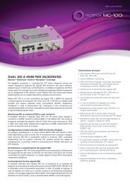
Diagram 1: Frames (fields) of standard RS-170A video with electrical voltage levels<br />
Even<br />
Field 0<br />
Odd<br />
Field 0<br />
Even<br />
Field 1<br />
Frame 0 Frame 1<br />
2<br />
Non-standard video formats usually differ from standard video in their<br />
timings and signal characteristics. Some examples of non-standard formats<br />
include high resolution, negative-going analog and digital video. High<br />
resolution video includes those cameras with spatial resolution of 1024 pixels<br />
x 1024 lines or higher; requiring a higher sampling rate (MHz) by the frame<br />
grabber. Negative-going video is an analog video signal where white or bright<br />
pixel data is represented by a more negative electrical value than a black or<br />
dark pixel. Digital video is a digitized waveform of RS-170A, NTSC, CCIR, PAL or<br />
non-standard video signals where the sync, blanking and saturation levels<br />
have been assigned a digital value. Additional discussion of non-standard<br />
video includes asynchronous reset, external exposure control and line scan.<br />
Standard analog format<br />
Standard cameras use a CCD (charged coupled device) array as an optical<br />
sensor which reads out a single interlaced frame made up of two fields<br />
(even and odd). The even field contains only even numbered lines and the<br />
odd field contains only odd numbered lines of video information.<br />
RS-170A is a standard monochrome composite video signal that contains<br />
both timing and image information in a single signal. This monochrome<br />
video is a 525 line system with a frequency of 30 frames (60 fields) per<br />
second. RS-170A has a 1 volt video signal amplitude, is 2:1 interlaced scan<br />
and has a standard sampling field or digitizing frequency providing a 4:3<br />
aspect ratio. Since the video signal ranges from -0.286V to +0.714V, it has<br />
an amplitude of 1V.<br />
The portion of the signal that lies above +0.054V, called the black level,<br />
contains active video, while the portion below +0.054V contains all sync<br />
information (e.g., blanking, horizontal and vertical). The saturation value<br />
of the RS-170A signal, called the reference white level, corresponds to a<br />
voltage of +0.714V. The reference black level corresponds to a voltage of<br />
+0.054V. An example of RS-170A video can be viewed in Diagram 1 along<br />
with its electrical representations.<br />
Odd<br />
Field 1<br />
Reference<br />
White Level (+0.714V)<br />
Black Level (+0.054V)<br />
Blanking Level (+0V)<br />
Sync Tip (-0.286V)
Blanking intervals<br />
A video signal has both vertical and horizontal blanking intervals. The<br />
vertical blanking occurs between two consecutive fields, while the<br />
horizontal blanking interval occurs between two lines. During the blanking<br />
period, the video signal is “blanked” by bringing down the voltage to a level<br />
equal to or below the black level (e.g., 0 volts for RS-170A).<br />
Vertical blanking<br />
Occurring between two fields, the vertical blanking interval is made up of a<br />
front and back porch (see Diagram 2). Each porch consists of a series of<br />
pulses (equalization pulses). Between the porches is the sync portion of the<br />
blanking interval which, depending on the signal type, will either contain a<br />
series of pulses (serration pulses) or no pulse at all (block sync).<br />
Serration pulses 3 are not used in conjunction with a frame grabber when a<br />
pixel clock is provided by the camera or frame grabber (see Pixel Clock<br />
section for more info).<br />
Diagram 2: Vertical blanking of standard RS-170A video<br />
Last Line<br />
Frame 0<br />
Front<br />
Porch<br />
Equalization<br />
Pulse<br />
Blanking Interval<br />
Vertical<br />
Sync<br />
Vertical Sync<br />
Pulse (portion)<br />
Vertical<br />
Serration<br />
Pulse<br />
Diagram 3: Horizontal blanking of standard RS-170A video with electrical voltage levels<br />
Front Porch<br />
(Line 0)<br />
Horizontal<br />
Sync (Line 2)<br />
Horizontal<br />
Blanking<br />
Interval<br />
3<br />
Horizontal blanking<br />
The horizontal blanking interval occurs between two lines and consists of the<br />
front porch of the previous line, the horizontal sync (hsync) pulse and the<br />
back porch of the current line (see Diagram 3). DC restoring of the signal,<br />
called clamping, usually occurs during the back porch of the hsync interval,<br />
although in some cameras it may occur during the front porch or in the sync<br />
pulse.<br />
Sync Pulses<br />
Blanking intervals contain vertical sync (vsync) and horizontal sync (hsync)<br />
pulses. A vsync pulse separates the two frames/fields and indicates the top<br />
of the next frame/field. A hsync pulse separates each line of video and<br />
indicates the beginning of a new scan line. During this period, the RS-170A<br />
video signal drops below 0V to -0.286V (from the blanking level down to the<br />
sync tip). Individual lines and hsync pulse locations can be seen in Diagram<br />
4 for a RS-170A video signal.<br />
Back Porch<br />
(Line 2)<br />
Back<br />
Porch<br />
Line 0 Line 2<br />
No Video<br />
Lines<br />
First Line<br />
Frame 1<br />
Reference<br />
White Level (+0.714V)<br />
Black Level (+0.054V)<br />
Blanking Level (OV)<br />
Sync Tip (-0.286V)
Diagram 4: Line timing<br />
Line 0 Line 2 Line 4 Line 6 Line 1 Line 3 Line 5 Line 7<br />
Diagram 5: Color horizontal line timings<br />
Front<br />
Porch<br />
Color coding<br />
horizontal sync pulses<br />
Even Field Odd Field<br />
Breezeway<br />
Hsync<br />
Color Phase (NTSC)<br />
yellow 167°<br />
cyan 283°<br />
green 241° Luminance Level<br />
magenta 61°<br />
red 103°<br />
blue 347°<br />
Color Burst<br />
Back Porch<br />
Video timing for color standards is similar to that of monochrome<br />
standards, except that the color information must be included with the<br />
signal by way of color phase and subcarriers, as well as information on how<br />
to decode the color information (see Diagram 5).<br />
Color phase, measured in degrees, is the timing relationship in a video<br />
signal that assures correct color hues. Color subcarrier is a clock used to run<br />
the color decoder (color burst). The subcarrier’s amplitude represents the<br />
saturation of the color, while the phase angle represents hue of the color.<br />
The color burst informs the decoder how to decode the color information<br />
contained in the line of active video information that follows.<br />
The color signal is also composed of horizontal and vertical blanking<br />
intervals, further made up of the front porch, the sync (horizontal and<br />
vertical) and the back porch. During horizontal blanking, the back porch is<br />
composed of a breezeway and the color burst. The breezeway is the portion<br />
of the video signal between the rising edge of the hsync and the start of the<br />
color burst.<br />
4<br />
white<br />
yellow<br />
cyan<br />
Individual Color Bar<br />
green<br />
magenta<br />
red<br />
blue<br />
black<br />
Color<br />
Saturation<br />
White Level<br />
Black Level<br />
Blanking Level<br />
Sync Level<br />
RS-330, RS-343A & CCIR analog<br />
video signals<br />
RS-330 and RS-343A are monochrome video standards based on the RS-170<br />
standard that have additional signal characteristics by way of modified<br />
timing waveforms and tighter tolerances. With the RS-330 standard, the<br />
output is a composite analog signal without serration pulses during the sync<br />
period, known as block sync4 (see Diagram 6). The RS-343A is for<br />
high-resolution video signals containing between 675 and 1023 lines per image<br />
frame.<br />
The CCIR (Comité Consultatif International des Radiocommunications) video<br />
standard is used generally in European countries. This monochrome video<br />
standard is a 625-line system with a frame rate of 25 frames (50 fields) per<br />
second. CCIR is similar to RS-170A in that it has a 1 volt video signal<br />
amplitude, is 2:1 interlaced scan and has a standard sampling field or<br />
digitizing frequency providing a 4:3 aspect ratio. The CCIR timing for the sync<br />
signals is similar to the RS-170A, except for the absence of the pedestal (black<br />
and blanking levels are equal).
Diagram 6: Vertical blanking RS-330 video<br />
Last Line<br />
Frame 0<br />
Front<br />
Porch<br />
Blanking Interval<br />
Block<br />
Sync<br />
Video timings used for building<br />
DCFs<br />
The respective widths of the sync pulse, back porch, active video period and<br />
front porch are known as the video timings of the camera. These timings are<br />
required when building a digitizer configuration file (DCF) 5 using <strong>Matrox</strong><br />
Intellicam camera interface software and can be read off of the timing<br />
diagrams in the camera manual. To be certain that you have a good<br />
understanding of the video characteristics (timings, etc.), complete the Video<br />
Specification Form found on our website (www.matrox.com/imaging). Table 1<br />
provides an example of timings used to build DCFs for RS-170A or CCIR video<br />
signals.<br />
Pixel clock<br />
A pixel clock is a timing signal used to divide the incoming line of video into<br />
pixels. The pixel clock is derived from either the camera or the frame grabber<br />
(refer to your camera manual to determine if the camera provides a pixel<br />
clock). It may be necessary to generate a pixel clock using the frame grabber's<br />
phase-locked loop (PLL). To generate a pixel clock, the PLL uses a reference<br />
signal. The reference signal can be either the frame grabber's on-board crystal<br />
oscillator or an external line sync (i.e., hsync) when periodic.<br />
Diagram 7: Pixel Jitter<br />
HSYNC<br />
Pixel Clock<br />
P = Pixels<br />
P -x ns<br />
± Xns*<br />
P +x ns<br />
P<br />
5<br />
Back<br />
Porch<br />
No Video<br />
Lines<br />
First Line<br />
Frame 1<br />
In some situations, a clock exchange will occur between the camera and the<br />
frame grabber. Initially the frame grabber will supply a pixel clock to the<br />
camera. The camera, in return, will generate a new pixel clock and return this<br />
pixel clock along with the video data to the frame grabber to insure that the<br />
incoming video data is in phase with the pixel clock used to digitize or sample<br />
this video data. A phase difference may result from internal delays created by<br />
digital circuitry in the camera.<br />
Pixel jitter is the timing accuracy of the pixel clock measured in nanoseconds<br />
by the variance in the rising edge of the pixel clock with respect to the falling<br />
edge of the hsync. Pixel jitter is introduced by either the camera (in the pixel<br />
clock or the hsync generated from the camera) or by the frame grabber's PLL<br />
(which can introduce additional pixel jitter). As a result of pixel jitter, the<br />
incoming video data may be digitized late or early resulting in inaccurate pixel<br />
representation (see Diagram 7). Generating the pixel clock from the frame<br />
grabber's PLL based on a stable reference will lower the pixel jitter to a value<br />
that will produce results well within an accurate range.<br />
If the pixel clock is accurate, the video<br />
signal will be digitized at exactly point<br />
‘P’ with a corresponding grayscale<br />
intensity value. A pixel jitter of +/- ns<br />
means that the video may be digitized<br />
late or early and be represented with a<br />
higher or lower grayscale intensity<br />
value.
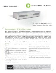
Table 1: RS-170A and CCIR Signal Characteristics<br />
RS-170A CCIR<br />
# of raster lines/frame 525 625 Lines<br />
# of raster lines/field 262.5 312.5 Lines<br />
V total displayed lines/frame 485 575 Lines<br />
V total displayed lines/field 242.5 282.5 Lines<br />
V front porch/field 3.0 2.5 Lines<br />
V sync/field 3.0 2.5 Lines<br />
equalization pulse width 2.3± 1 2.35± 1 µs<br />
V back porch/field 14 20 Lines<br />
V blanking/field 20 25 Lines<br />
line frequency 15.734 15.625 KHz<br />
line duration 63.556 64.000 µs<br />
line blanking 10.9 ± 0.2 12.00 ± 0.3 µs<br />
front porch 1.5 ± 0.1 1.5 ± 0.3 µs<br />
H sync pulse width 4.7 ± 0.1 4.7 ± 0.2 µs<br />
back porch 4.7 5.8 µs<br />
active horizontal 52.66 52 µs<br />
nominal bandwidth 4.2 5.0, 5.5, 6.0 MHz<br />
effective horizontal resolution 640 768 Pixels<br />
output voltage 1.0 1.0 Vp-p<br />
video voltage 0.7 0.7 Vp-p<br />
sync voltage 0.3 0.3 Vp-p<br />
impedance 75 75 ohm<br />
pedestal 0.054 n/a V<br />
Non-standard video<br />
Analog progressive scan<br />
With progressive scan video, also known as non-interlaced, the sensor reads<br />
out the entire frame (containing both even and odd components) at one<br />
time. The frame is not composed of separate fields as with standard analog<br />
video such as RS-170A.<br />
High resolution<br />
High resolution video includes any cameras with a spatial resolution of 1024<br />
pixels x 1024 lines and higher. The difference between this video signal and<br />
standard video signals is the difference in the timing specifications and the<br />
signal period, along with the required increase in sampling rates by the frame<br />
grabber.<br />
Negative-going video<br />
Negative-going video is an analog video signal where white or bright pixel data<br />
is represented by a more negative electrical value than a black or dark pixel.<br />
Diagram 8 represents how negative-going video usually appears, however,<br />
other variations of negative-going video may exist.<br />
6<br />
Digital video<br />
Digital video is a video signal where data-carrying-signals are restricted to<br />
either one of two voltages levels, corresponding to logic 1 or 0 (see Diagram 9).<br />
This type of representation of data is beneficial because it can be transmitted<br />
with a minimum of noise and distortion introduction. Each pixel in digital video<br />
is represented by a n-bit system (see Diagram 10), where a value between 0<br />
and 2 n represents the brightness value (e.g. , an 8-bit system will have a value<br />
between 0 and 255 to represent the brightness value of a pixel). Each<br />
additional captured bit provides more information about the pixel. For<br />
monochrome images, this means that as one increases the number of bits<br />
captured, higher shades of gray are reproduced resulting in a more accurate<br />
representation of the subject.<br />
Digital video data is usually transmitted on a pixel-by-pixel basis in the form<br />
of several bits in parallel. Each bit is transmitted on an individual signal line<br />
(with TTL logic levels standard) or a pair of signal lines such as differential<br />
RS-422 or EIA -644 (LVDS) standards. Other digital formats include IEEE-1394<br />
and <strong>Camera</strong> Link.
Digital video (continued)<br />
TTL (Transistor-Transistor Logic) is a medium/high speed family of logic<br />
integrated circuits, while RS-422 is a medium range differential signaling pair<br />
standard. With RS-422, digital information can travel over a longer distance<br />
without the introduction of as much noise (random image information known<br />
as snow or flecks) as with a TTL signal line. EIA-644 (LVDS) is a short range<br />
standard with a high transmission speed, low noise and low power requirement.<br />
IEEE-1394 digital serial link is a high speed, bi-directional communication for<br />
device control and video transfer. IEEE 1394 video, based on the Digital <strong>Camera</strong><br />
(DCAM) Specification, provides video, control and camera power in a single<br />
cable design, as well as enough bandwidth to handle the video transfer<br />
demands at typical image resolutions and frame rates. IEEE-1394 provides<br />
support for two types of data transfer modes depending on the nature of the<br />
data. Asynchronous data transfer mode provides guaranteed delivery of<br />
control commands, while Isochronous data transfer mode provides guaranteed<br />
bandwidth for time-critical data such as live video.<br />
Diagram 8: Negative-going Video<br />
Frame 0 Frame 1<br />
Diagram 9: Equivalence between analog composite and digital video<br />
Front Porch<br />
Hsync<br />
Back Porch<br />
Line n Line n+1<br />
* Pixel data is represented here as a single line for all bits, see Diagram 10 for an uncompressed view of the pixel data.<br />
7<br />
<strong>Camera</strong> Link is based on National Semiconductor's Channel Link technology<br />
that combines traditional low-voltage differential signal (LVDS) with serial<br />
digital data flow. It offer high-speed data transfer rates of up to 2.38 Gbit/s<br />
with transmission speeds up to 85 MHz. <strong>Camera</strong> Link supports bi-directional<br />
communication for camera control and serial communication, as well as video<br />
data over cable lengths as long as 10 meters (32.8 feet).<br />
Analog<br />
Composite<br />
Video<br />
Sync Tip<br />
Hsync (separate)<br />
Pixel Data<br />
(all bits*)<br />
Blanking Level<br />
Black Level<br />
Reference<br />
White Level<br />
Digital<br />
Video
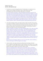
Diagram 10: 8-bit digital video.<br />
Modes of operation<br />
Typically cameras can be operated in one of several different modes. For area<br />
scan cameras, modes include continuous, pseudo-continuous, trigger,<br />
asynchronous reset, control and long exposure (integration). Line scan<br />
cameras may be operated in fixed line scan rate, variable line scan rate mode,<br />
and line scan rate and variable frame size mode. The connections mentioned in<br />
the discussion of modes are general. Some cameras may require additional<br />
connections for signals such as auxiliary control, external trigger, etc. All<br />
required connections should be specified in the camera manual. The use of<br />
“internal” in this discussion refers to the camera’s end and “external” refers to<br />
the board’s end. Horizontal sync and vertical sync is referred to as hsync and<br />
vsync respectively. Bi-directional signals represent those that can be supplied<br />
by either the frame grabber or the camera. Terminology varies from one<br />
manufacturer to another, so the definitions found here are as <strong>Matrox</strong> Imaging<br />
uses them.<br />
Diagram 11: Continuous mode<br />
1 n<br />
8<br />
Area scan camera modes<br />
1. Continuous (Diagram 11)<br />
Each pixel is defined by the<br />
sampling of a single line at a<br />
certain point in time. The<br />
pixel can be represented with<br />
256 brightness values, as<br />
shown in this 8-bit example<br />
(2 8 = 256)<br />
The camera continuously outputs images at a fixed frame rate, usually 30<br />
frames (60 fields) per second or 25 frames (50 fields) per second being North<br />
American and European timings respectively. In general, the exposure time is<br />
the reciprocal of the frame rate. If supported by the camera, it may also be<br />
possible to decrease the exposure period. The frame rate, however, is fixed and<br />
cannot be changed. Exposure of the current frame and transfer of the previous<br />
frame occur concurrently in continuous mode. Therefore, exposure time in this<br />
mode cannot exceed the reciprocal of the frame rate (i.e., frame transfer<br />
time.<br />
Frame n Frame n+1 Frame n+2 Frame n+3<br />
Exposure: Frame n+1<br />
Transfer: Frame n<br />
1. Analog or digital<br />
2. Bi-directional and separate in some cases<br />
3. Internal or external pixel clock<br />
<strong>Camera</strong><br />
Exposure: Frame n+2 Exposure: Frame n+3<br />
Transfer: Frame n+1 Transfer: Frame n+2<br />
Video1 HSYNC2 Pixel Clock 3<br />
Exposure: Frame n+4<br />
Transfer: Frame n+3
1. Continuous (continued)<br />
If the output of the camera is an analog video signal, where both the hsync and<br />
the vsync are combined with video data to form a composite video signal, then<br />
that signal alone is required by the frame grabber for operation in continuous<br />
mode. While not typical, some cameras may output an analog video signal<br />
where only the hsync is composite. In this case, a separate digital vsync signal<br />
(e.g., a frame enable or a trigger signal) is required and supplied by the<br />
camera to the frame grabber or vice-versa. Separate digital syncs may also be<br />
used when the output of the camera is a fully composite analog signal. The<br />
analog syncs included in the video signal are simply ignored.<br />
If the output of the camera is a digital video signal, both the hsync and the<br />
vsync are usually separate digital signals provided by the camera or frame<br />
grabber. Some cameras combine the hsync and the vsync into a single digital<br />
composite sync. Finally, a pixel clock may be provided by the camera or<br />
supplied by the frame grabber if required. They can be supplied by both in the<br />
case of clock exchange (see previous section, Pixel Clock).<br />
2. Pseudo-continuous (Diagram 12)<br />
The camera continuously outputs images at a frame rate that is determined by<br />
the exposure time and the frame transfer time. The frame rate is usually less<br />
than 30 frames (60 fields) or 25 frames (50 fields) per second for North<br />
American and European formats respectively. The exposure time may be<br />
selected by adjusting the camera, however, the frame transfer time is fixed<br />
and is characteristic of the camera. Exposure and transfer of a frame occurs<br />
sequentially (see diagram 12). Exposure of a new frame only starts once the<br />
previous frame has been fully transferred, therefore, the frame rate is the<br />
reciprocal of the sum of the exposure time and the frame transfer time.<br />
Diagram 12: Pseudo-continuous mode<br />
Exposure:<br />
Frame n<br />
<strong>Camera</strong><br />
1. Analog or digital<br />
2. Bi-directional and separate in some cases<br />
3. Internal or external pixel clock<br />
Frame n<br />
Transfer:<br />
Frame n<br />
Video1 HSYNC2 Exposure:<br />
Frame n+1<br />
Pixel Clock 3<br />
9<br />
The camera sets an upper limit on the exposure time. Unlike continuous mode,<br />
the exposure time can be much longer than the frame transfer time. The signals<br />
involved in this mode are the video output (analog or digital) and syncs. As<br />
with continuous mode, these signals may be combined with video data<br />
(composite) or separate digital syncs can be used.<br />
3. Trigger (Diagram 13)<br />
The camera continuously outputs images at a fixed frame rate as in continuous<br />
mode, however an external trigger signal is provided to the frame grabber. The<br />
external trigger signal causes the frame grabber to grab on the next vsync of<br />
the video signal, thereby acquiring the next frame. Any additional external<br />
trigger signals will be ignored until the current frame period is over.<br />
To ensure the capture of an image, the shortest time between external trigger<br />
signals should be greater than the sum of the exposure time and the frame<br />
transfer time. In addition to the external trigger signal, the video output and<br />
syncs are provided to the frame grabber. The trigger mode is used to capture a<br />
single image or a sequence of images. In general, exposure time details are<br />
similar to those described in Continuous mode.<br />
4. Asynchronous reset (Diagram 14)<br />
Either an external trigger signal is provided to the frame grabber or the frame<br />
grabber has an internal trigger which can be periodic or aperiodic (software<br />
controlled). The frame grabber in turn triggers the asynchronously resettable<br />
camera to initiate exposure. The trigger signal from the frame grabber to the<br />
camera is referred to as the exposure signal and is controlled through the DCF<br />
file in <strong>Matrox</strong> Intellicam. The camera is resynchronized on the arrival of the<br />
exposure signal. The delay from the time the frame grabber is triggered to the<br />
time it starts exposing is programmable.<br />
Frame n+1<br />
Transfer:<br />
Frame n+1<br />
Exposure:<br />
Frame n+2
Diagram 13: Trigger mode<br />
External<br />
Trigger<br />
Trigger signal can arrive at any<br />
point during a frame however the<br />
frame acquired will occur after<br />
the next valid VSYNC<br />
1. Analog or digital<br />
2. Bi-directional HSYNC and VSYNC<br />
3. Internal or external pixel clock<br />
4. Asynchronous reset (continued)<br />
<strong>Camera</strong><br />
Acquired<br />
Frame<br />
Video 1<br />
SYNC 2<br />
Pixel Clock 3<br />
External Trigger<br />
There are three versions of the asynchronous reset mode utilized by cameras;<br />
vertically asynchronously resettable,vertically and horizontally asynchronously<br />
resettable and fully asynchronously resettable. A camera can be identified as:<br />
• vertically asynchronously resettable when only the vertical timings are reset on<br />
the exposure pulse;<br />
• vertically and horizontally asynchronously resettable if both the vertical<br />
timings and the horizontal timings are reset on the exposure pulse;<br />
• and fully asynchronously resettable when the vsync, the hsync and the pixel<br />
clock are reset on the exposure signal.<br />
Diagram 14: Asynchronous reset mode<br />
External<br />
Trigger<br />
Exposure<br />
Signal<br />
Programmable delay<br />
controlled by frame grabber<br />
1. Analog or digital<br />
2. Bi-directional HSYNC and VSYNC<br />
3. Internal or external pixel clock<br />
<strong>Camera</strong><br />
Exposure<br />
time<br />
Fixed or programmable<br />
exposure period controlled<br />
by frame grabber<br />
Acquired<br />
Frame<br />
Video1 SYNC2 Pixel Clock<br />
Exposure<br />
3<br />
External Trigger<br />
10<br />
Examine the timing diagrams that are found in the camera manual to<br />
determine which of the three cases corresponds to the asynchronous reset<br />
mode of your particular camera.<br />
In this mode, the exposure time is controlled by way of the camera or the frame<br />
grabber. Some cameras will ignore an exposure signal that arrives before the<br />
current frame period is over, while others will resynchronize on this new signal,<br />
discarding all current video information. Generally, the shortest time between<br />
external trigger signals should be greater than the sum of the exposure signal<br />
width, the exposure time and the frame transfer time to avoid loss of<br />
information. The signals utilized in this mode are an external trigger signal<br />
provided to the frame grabber, an exposure signal supplied from the frame<br />
grabber to the camera, the video output (analog or digital) and syncs.
5. Control (Diagram 15)<br />
The exposure time is controlled externally, by way of the frame grabber. In<br />
most cases, the camera is triggered by an asynchronous reset signal, which is<br />
initiated by an external trigger source by way of the frame grabber. The<br />
asynchronous reset signal is referred to as the exposure signal. The delay from<br />
the time the camera is triggered to the time it starts exposing is<br />
programmable. The delay between exposure and frame transfer is fixed and is a<br />
characteristic of the camera.<br />
In this mode, the camera is resynchronized on the exposure signal. The width of<br />
the exposure signal determines the exposure time and is controlled in the DCF<br />
file through <strong>Matrox</strong> Intellicam. Some cameras will ignore an exposure signal<br />
that arrives before the current frame period is over, while others will<br />
resynchronize on this new signal and discards all current information. To avoid<br />
loss of information, the shortest time between external trigger signals should<br />
be greater than the sum of the exposure signal width and the frame transfer<br />
time. The signals utilized in this mode are an external trigger signal provided to<br />
the frame grabber, an exposure signal supplied by the frame grabber to the<br />
camera, the video output (analog or digital) and syncs. Control mode is<br />
employed for user control over the start and exposure time of an image.<br />
5. Long exposure or integration (Diagram 16)<br />
The exposure time can be controlled by the camera or the frame grabber. In<br />
this mode, an external trigger signal is provided to the frame grabber, which in<br />
turn triggers the camera. The trigger signal from the frame grabber to the<br />
camera is referred as the exposure signal and is controlled in the DCF file<br />
through <strong>Matrox</strong> Intellicam.<br />
Diagram 15: Control mode<br />
External<br />
Trigger<br />
Exposure<br />
Signal<br />
1. Analog or digital<br />
2. Bi-directional HSYNC and VSYNC<br />
3. Internal or external pixel clock<br />
Programmable delay<br />
controlled by frame grabber<br />
Exposure Exposure<br />
Timetime<br />
<strong>Camera</strong><br />
Fixed or programmable<br />
exposure period controlled<br />
by frame grabber<br />
Pixel Clock<br />
Exposure<br />
3<br />
External Trigger<br />
11<br />
With most cameras the exposure signal is latched on the horizontal sync and is<br />
used to initiate frame transfer on the video’s next vertical sync. The exposure<br />
time is generally specified in terms of an integer number of fields or frames,<br />
where one frame time (the frame transfer time) is equal to the reciprocal of<br />
the frame rate of the camera when operated in continuous mode; one field<br />
time is half of a frame time. This mode can be used when an exposure time<br />
greater than one frame time is desired. Most cameras will ignore the end of an<br />
exposure signal that arrives before the current frame period is over, while<br />
others will latch onto the signal and initiate the next exposure immediately<br />
afterward.<br />
To ensure the capture of an image:<br />
• if the exposure is controlled by the camera, the shortest time between external<br />
trigger signals should be greater than the sum of the exposure signal width, the<br />
exposure time and the frame transfer time;<br />
• if the exposure is controlled by the frame grabber, the shortest time between<br />
external trigger signals should be greater than the sum of the exposure signal<br />
width and the frame transfer time.<br />
The width of the exposure signal determines the exposure time and is adjusted<br />
in the DCF file through <strong>Matrox</strong> Intellicam. The signals used in this mode are an<br />
external trigger signal provided to the frame grabber, an exposure signal<br />
supplied by the frame grabber to the camera, the video output (analog or<br />
digital) and syncs.<br />
Fixed delay<br />
controlled by camera<br />
Video1 SYNC2 Acquired<br />
Frame
Diagram 16: Long exposure or integration mode<br />
External<br />
Trigger<br />
Exposure<br />
Signal<br />
1. Analog or digital<br />
2. Bi-directional HSYNC and VSYNC<br />
3. Internal or external pixel clock<br />
Line Scan <strong>Camera</strong> Modes<br />
<strong>Camera</strong><br />
1. Fixed (Continuous) line scan rate (Diagram 17)<br />
Exposure time<br />
Video 1<br />
SYNC 2<br />
Pixel Clock 3<br />
Exposure<br />
External Trigger<br />
An hsync signal is supplied to the line scan camera by the frame grabber with a<br />
frequency that determines the line scan rate. The line transfer period is<br />
initiated upon the rising edge of the hsync and is followed by the line readout<br />
period. Unless the camera features exposure control, the exposure time is the<br />
reciprocal of or inversely proportional to the line scan rate.<br />
Diagram 17: Fixed (Continuous) lines scan rate mode<br />
Pixel Clock<br />
HSYNC<br />
Line Valid<br />
1. Analog or digital<br />
2. Internal or external pixel clock<br />
12<br />
End of Exposure signal can arrive at any point<br />
during the second frame but acquisition will<br />
occur on the next frame<br />
Frame n Frame n+1 Acquired<br />
Frame<br />
Line<br />
transfer<br />
(Line n)<br />
<strong>Camera</strong><br />
Exposure time<br />
(Line n+1)<br />
Line readout<br />
(Line n)<br />
Acquired<br />
line<br />
Video 1<br />
HSYNC<br />
Pixel Clock 2<br />
A pixel clock is usually supplied to the camera by the frame grabber. There are<br />
some cameras that return an additional clock (strobe) that is derived from<br />
the first clock. This clock is used as the real pixel clock and are known as a<br />
clock exchange. The signals utilized in this mode are a pixel clock, hsync, a<br />
returned strobe signal (with some cameras) and video output (analog or<br />
digital).<br />
Line<br />
transfer<br />
(Line n+1)
2. Variable line scan rate (Diagram 18)<br />
An external trigger signal is provided to the frame grabber, which in turn<br />
triggers the camera to initiate line readout. The trigger from the frame grabber<br />
to the camera is called an exposure signal. The frequency of the external<br />
trigger signal determines the line scan rate and it must be greater than the<br />
exposure time and the line transfer time.<br />
• With external exposure control, the length of the exposure signal will specify<br />
the exposure time.<br />
• With internal exposure control, exposure time is set on the camera (through<br />
switches or control bits) and is specified by the exposure signal period plus line<br />
transfer delay.<br />
• With no exposure control, the exposure time will be equal to the reciprocal of<br />
the line rate. If the line rate varies over time, the exposure time will also vary<br />
causing intensity variations over time.<br />
A pixel clock is usually supplied to the camera by the frame grabber. Certain<br />
cameras return an additional clock (strobe) to the frame grabber for use as<br />
the real pixel clock (clock exchange), which is derived from the pixel clock<br />
generated by the frame grabber. The signals utilized in this mode are an<br />
external trigger signal provided to the frame grabber, a pixel clock and<br />
exposure signal both supplied by the frame grabber to the camera, a returned<br />
strobe signal (in some cameras), and a video output (analog or digital). The<br />
camera can also return a line valid signal.<br />
Diagram 18: Variable line scan rate mode<br />
Pixel Clock<br />
External Trigger<br />
Exposure Signal<br />
Line Valid<br />
delay 3<br />
Line transfer<br />
1. With external exposure control<br />
2. With internal exposure control<br />
3. Programmable delay controlled by frame grabber<br />
4. Analog or digital<br />
5. Internal or external pixel clock<br />
<strong>Camera</strong><br />
Exposure time 1<br />
Exposure time 2<br />
Video 4<br />
Pixel Clock 5<br />
Exposure<br />
13<br />
3. Line scan rate and variable frame size (Diagram 19)<br />
Two external trigger signals (line and frame) are provided to the frame<br />
grabber, which in turn triggers the camera to initiate line and frame (virtual)<br />
readout. The trigger from the frame grabber to the camera is called the<br />
exposure signal. The line trigger is continuous with a variable rate. The line<br />
trigger provided to the frame grabber in turn triggers the camera to initiate the<br />
line readout. At the arrival of the frame trigger, which may also may be variable,<br />
a specified number of lines are captured to create a virtual frame.<br />
A pixel clock is usually supplied to the camera by the frame grabber. The<br />
signals utilized in this mode (see Diagram 19) are external line and frame<br />
trigger signals provided to the frame grabber, a pixel clock and exposure signal<br />
both supplied by the frame grabber to the camera, a returned strobe signal (in<br />
some cameras), and a video output (analog or digital).<br />
Line readout<br />
Acquired<br />
line<br />
External Trigger
Diagram 19: Line scan rate and variable frame size mode<br />
Frame Trigger<br />
Line Trigger<br />
Line Valid<br />
1. Analog or digital<br />
2. Internal or external pixel clock<br />
Endnotes<br />
variable<br />
<strong>Camera</strong><br />
Line Trigger<br />
Video 1<br />
Pixel Clock 2<br />
Exposure<br />
Frame Trigger<br />
14<br />
variable<br />
virtual frame of n+x lines<br />
1. <strong>Matrox</strong> provides predefined DCFs for RS-170, CCIR, and many non-standard formats, which can be used as is or modified<br />
to meet specific requirements.<br />
2. YIQ is the color space used in the NTSC color system, where the Y component is the black and white portion of the<br />
image; and the I and Q parts are the color components. With YUV (used by the PAL color system) the Y component is the<br />
black and white portion of the image; and the U and V parts are the color components.<br />
3. These pulses were used to ensure correct 2:1 interlacing in earlier television video signals.<br />
4. This characteristic of RS-330 video can prevent a frame grabber from locking onto a video source. Consult with <strong>Matrox</strong><br />
to see if your camera is compatible with our frame grabbers.<br />
5. <strong>Matrox</strong> provides predefined DCFs for RS-170, CCIR, and many non-standard formats, which can be used as is or modified<br />
to meet specific requirements.
Table 2: Mode Reference<br />
Area Scan <strong>Camera</strong>s<br />
<strong>Camera</strong> Modes Connections<br />
1. Continuous<br />
- continuous video<br />
- internal exposure control<br />
- exposure time cannot exceed frame transfer time<br />
- fixed frame rate is independent of exposure time<br />
2. Pseudo-continuous<br />
- Pseudo-continuous video<br />
- internal exposure control<br />
- exposure time can be much longer than frame transfer time<br />
- frame rate is a function of exposure time<br />
3. Trigger<br />
- internal exposure control<br />
- external trigger<br />
4. Asynchronous reset<br />
- internal or external exposure control<br />
- internal or external trigger<br />
5. Control<br />
- external exposure control<br />
- external trigger<br />
6. Long exposure or integration<br />
- internal or external exposure control<br />
- exposure times longer than one frame<br />
- external trigger<br />
Line Scan <strong>Camera</strong>s<br />
NOTE: The use of INTERNAL refers to the camera’s end and EXTERNAL to the frame grabber's end.<br />
15<br />
- video and sync signals between camera and frame grabber<br />
(syncs can be provided from frame grabber)<br />
- video and sync signals between camera and frame grabber<br />
- video and sync signals connected between camera and frame grabber<br />
- external trigger signal connected to frame grabber<br />
- video, sync and exposure (frame grabber acting has asynchronous reset)<br />
signals connected between camera and frame grabber<br />
- external trigger signal connected to frame grabber<br />
- video, sync and exposure (frame grabber acting has asynchronous reset plus<br />
actual exposure) signals connected between camera and frame grabber<br />
- external trigger signal connected to frame grabber<br />
- video, sync and exposure (trigger) signals connected between camera and<br />
frame grabber<br />
- external trigger signal connected to frame grabber<br />
<strong>Camera</strong> Modes Connections<br />
1. Fixed (Continuous) line scan rate<br />
- line scan rate determined by frequency of horizontal sync signal<br />
- internal exposure control<br />
2. Variable line scan rate<br />
- line scan rate determined by time between external trigger pulses<br />
- internal or external exposure time control<br />
3. Line scan rate and variable frame size<br />
- external line and frame triggers<br />
- line scan rate determined by time between external trigger pulses<br />
- internal or external exposure time control<br />
- video and sync signals between camera and frame grabber<br />
(sync can be provided from frame grabber)<br />
- video, sync and exposure (trigger) signals connected between camera and<br />
frame grabber<br />
- external trigger signal connected to frame grabber<br />
- video, sync and exposure (trigger) signals connected between camera and<br />
frame grabber<br />
- external line and frame trigger signal connected to frame grabber
Corporate headquarters:<br />
Canada and U.S.A.<br />
<strong>Matrox</strong> Electronic<br />
Systems Ltd.<br />
1055 St. Regis Blvd.<br />
Dorval, Quebec H9P 2T4<br />
Canada<br />
Tel: (514) 685-2630<br />
Fax: (514) 822-6273<br />
Offices:<br />
Europe, Middle East & Africa<br />
<strong>Matrox</strong> VITE Limited<br />
Sefton Park<br />
Stoke Poges<br />
Buckinghamshire<br />
SL2 4JS<br />
U.K.<br />
Tel: 01753 665511<br />
Fax: 01753 665599<br />
France<br />
<strong>Matrox</strong> France SARL<br />
2, rue de la Couture<br />
Silic 225<br />
94528 Rungis Cedex<br />
Tel: (0) 1 45-60-62-00<br />
Fax: (0) 1 45-60-62-05<br />
Germany<br />
<strong>Matrox</strong> Electronic<br />
Systems GmbH<br />
Inselkammerstr. 8<br />
D-82008 Unterhaching<br />
Germany<br />
Tel: 089/621 70-0<br />
Fax: 089/614 9743<br />
For more information, please call:<br />
1-800-804-6243 (toll free in North America) or (514) 822-6020<br />
or e-mail: imaging.info@matrox.com or<br />
www.matrox.com/imaging<br />
All trademarks by their respective owners are hereby acknowledged. <strong>Matrox</strong><br />
Electronic Systems, Ltd. reserves the right to make changes in specifications at any<br />
time and without notice. The information furnished by <strong>Matrox</strong> Electronic Systems,<br />
Ltd. is believed to be accurate and reliable. However, no responsibility license is<br />
granted under any patents or patent rights of <strong>Matrox</strong> Electronic Systems Ltd.<br />
07-18-2003.<br />
17