

SL811HS Embedded USB Host/Slave Controller
SL811HS Embedded USB Host/Slave Controller
SL811HS Embedded USB Host/Slave Controller

Create successful ePaper yourself
Turn your PDF publications into a flip-book with our unique Google optimized e-Paper software.
<strong>SL811HS</strong><br />
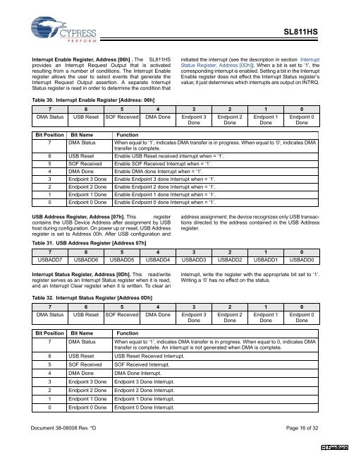
Interrupt Enable Register, Address [06h] . The <strong>SL811HS</strong><br />
provides an Interrupt Request Output that is activated<br />
resulting from a number of conditions. The Interrupt Enable<br />
register allows the user to select events that generate the<br />
Interrupt Request Output assertion. A separate Interrupt<br />
Status register is read in order to determine the condition that<br />
initiated the interrupt (see the description in section Interrupt<br />
Status Register, Address [0Dh]). When a bit is set to ‘1’, the<br />
corresponding interrupt is enabled. Setting a bit in the Interrupt<br />
Enable register does not effect the Interrupt Status register’s<br />
value; it just determines which interrupts are output on INTRQ.<br />
Table 30. Interrupt Enable Register [Address: 06h]<br />
7 6 5 4 3 2 1 0<br />
DMA Status <strong>USB</strong> Reset SOF Received DMA Done Endpoint 3<br />
Done<br />
Endpoint 2<br />
Done<br />
Endpoint 1<br />
Done<br />
Endpoint 0<br />
Done<br />
Bit Position Bit Name Function<br />
7 DMA Status When equal to ‘1’, indicates DMA transfer is in progress. When equal to ‘0’, indicates DMA<br />
transfer is complete.<br />
6 <strong>USB</strong> Reset Enable <strong>USB</strong> Reset received interrupt when = ‘1’.<br />
5 SOF Received Enable SOF Received Interrupt when = ‘1’.<br />
4 DMA Done Enable DMA done Interrupt when = ‘1’.<br />
3 Endpoint 3 Done Enable Endpoint 3 done Interrupt when = ‘1’.<br />
2 Endpoint 2 Done Enable Endpoint 2 done Interrupt when = ‘1’.<br />
1 Endpoint 1 Done Enable Endpoint 1 done Interrupt when = ‘1’.<br />
0 Endpoint 0 Done Enable Endpoint 0 done Interrupt when = ‘1’.<br />
<strong>USB</strong> Address Register, Address [07h]. This register address assignment, the device recognizes only <strong>USB</strong> transactions<br />
contains the <strong>USB</strong> Device Address after assignment by <strong>USB</strong><br />
host during configuration. On power up or reset, <strong>USB</strong> Address directed to the address contained in the <strong>USB</strong> Address<br />
register.<br />
register is set to Address 00h. After <strong>USB</strong> configuration and<br />
Table 31. <strong>USB</strong> Address Register [Address 07h]<br />
7 6 5 4 3 2 1 0<br />
<strong>USB</strong>ADD7 <strong>USB</strong>ADD6 <strong>USB</strong>ADD5 <strong>USB</strong>ADD4 <strong>USB</strong>ADD3 <strong>USB</strong>ADD2 <strong>USB</strong>ADD1 <strong>USB</strong>ADD0<br />
Interrupt Status Register, Address [0Dh]. This read/write<br />
register serves as an Interrupt Status register when it is read,<br />
and an Interrupt Clear register when it is written. To clear an<br />
interrupt, write the register with the appropriate bit set to ‘1’.<br />
Writing a ‘0’ has no effect on the status.<br />
Table 32. Interrupt Status Register [Address 0Dh]<br />
7 6 5 4 3 2 1 0<br />
DMA Status <strong>USB</strong> Reset SOF Received DMA Done Endpoint 3<br />
Done<br />
Endpoint 2<br />
Done<br />
Endpoint 1<br />
Done<br />
Endpoint 0<br />
Done<br />
Bit Position Bit Name Function<br />
7 DMA Status When equal to ‘1’, indicates DMA transfer is in progress. When equal to 0, indicates DMA<br />
transfer is complete. An interrupt is not generated when DMA is complete.<br />
6 <strong>USB</strong> Reset <strong>USB</strong> Reset Received Interrupt.<br />
5 SOF Received SOF Received Interrupt.<br />
4 DMA Done DMA Done Interrupt.<br />
3 Endpoint 3 Done Endpoint 3 Done Interrupt.<br />
2 Endpoint 2 Done Endpoint 2 Done Interrupt.<br />
1 Endpoint 1 Done Endpoint 1 Done Interrupt.<br />
0 Endpoint 0 Done Endpoint 0 Done Interrupt.<br />
Document 38-08008 Rev. *D Page 16 of 32<br />
[+] Feedback


