You also want an ePaper? Increase the reach of your titles
YUMPU automatically turns print PDFs into web optimized ePapers that Google loves.
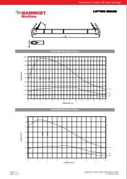
Crane Geometry:<br />
Indication A: Load Table for Sheerleg Mode<br />
Crane Confi guration SSL Sheerleg Mode<br />
Crane Duty Normal<br />
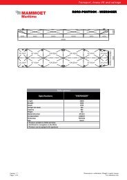
Head Duty Type <strong>Heavy</strong> [1600t]<br />
A-frame length [m] 67.2<br />
A-frame Maximum Angle [ø] 81.54<br />
Hsig & Maximum Period T 1m & 6s / 0.6m & 8.5s<br />
Superballast usage Stays Fixed to Deck and Fixed Ballast with a Triangle Spreader<br />
Capacity Deck Stays [t] 900<br />
Fixed Ballast on Ring [t] 380t at 11.83 [m]: 320 [t] lower ballast & 60t tray mass [lower and upper]<br />
Backmast Radius [m] 13.486 [m]<br />
Windspeed 12.86 [m/s]<br />
Max. Pitch [deg] 0.5<br />
Max. Roll [deg] 2<br />
Static Trim [deg] 0.5<br />
Static Heel [deg] 0.5<br />
Fhoist 1.1<br />
Fduty 1.05<br />
Sideload [deg] 2.5<br />
Offl load [deg] 1<br />
Auxiliary Hoist Max. Capacity [t] 30<br />
Reeving [-] 3<br />
Max sidelead [deg] 4<br />
Max offl ead [deg] 7<br />
Load Capacity Table<br />
Radius SWL<br />
Aframe<br />
Angle<br />
Notes<br />
• The mainboom is composed according to sketch (copied from in drawing<br />
A05-66000-14-01A)<br />
• Crane designed according: DIN 15018part1,3, DIN 15019part2, DIN<br />
15020part1 and DIN 1055part4<br />
• <strong>Lifting</strong> capacity for lifting on barge according to Lloyds Register of<br />
Shipping [code for lifting appliances in a marine environment January<br />
2003]<br />
• Weight of lower blocks, hoisting wire,slings, spreaders, aux. hoist, etc., is<br />
considered as part of the load.<br />
• The lifting capacity is only valid when the main-hoist is reeved according<br />
to the table<br />
• The weight of the ballast trays is counted as ballastweight.<br />
• Interpolation of working loads between radii is allowed.<br />
• Combined lifting of main hoist and auxiliary hoist is not allowed<br />
• The maximum sidelead of 4 degrees for the auxiliary hoist may not be<br />
6 | 7<br />
Height Reeving<br />
Minimum<br />
Required<br />
tugger<br />
capacity<br />
cross<br />
direction of<br />
the crane<br />
Minimum<br />
Required<br />
tugger<br />
capacity<br />
longitudonaldirection<br />
of the<br />
crane<br />
Minimum<br />
Required<br />
resultant<br />
tugger<br />
capacity<br />
[m] [t] [deg] [m] [-] [t] [t] [t]<br />
20 1017 81.54 71.42 22 44.4 17.7 47.8<br />
21 992 80.67 71.25 22 43.3 17.3 46.6<br />
22 969 79.81 71.07 22 42.3 16.9 45.5<br />
23 947 78.94 70.86 22 41.3 16.5 44.5<br />
24 926 78.07 70.65 22 40.4 16.2 43.5<br />
25 906 77.19 70.41 22 39.5 15.8 42.6<br />
26 886 76.31 70.16 22 38.6 15.5 41.6<br />
27 868 75.43 69.89 22 37.9 15.1 40.8<br />
28 850 74.54 69.61 22 37.1 14.8 39.9<br />
29 833 73.65 69.31 22 36.3 14.5 39.1<br />
30 817 72.76 68.99 22 35.6 14.3 38.4<br />
31 801 71.86 68.67 22 34.9 14.0 37.6<br />
32 786 70.95 68.31 22 34.3 13.7 36.9<br />
33 771 70.05 67.94 22 33.6 13.5 36.2<br />
34 758 69.14 67.56 22 33.1 13.2 35.6<br />
35 744 68.21 67.15 22 32.5 13.0 35.0<br />
36 732 67.29 66.72 22 31.9 12.8 34.4<br />
37 719 66.36 66.28 22 31.4 12.5 33.8<br />
38 707 65.42 65.82 22 30.8 12.3 33.2<br />
39 695 64.47 65.33 22 30.3 12.1 32.7<br />
40 684 63.51 64.83 22 29.8 11.9 32.1<br />
41 674 62.55 64.3 22 29.4 11.8 31.7<br />
42 663 61.58 63.75 22 28.9 11.6 31.1<br />
43 652 60.6 63.18 22 28.4 11.4 30.6<br />
44 643 59.61 62.59 22 28.0 11.2 30.2<br />
45 630 58.61 61.97 22 27.5 11.0 29.6<br />
46 612 57.59 61.33 22 26.7 10.7 28.8<br />
47 594 56.57 60.66 22 25.9 10.4 27.9<br />
48 576 55.53 59.97 22 25.1 10.1 27.1<br />
49 560 54.48 59.25 22 24.4 9.8 26.3<br />
50 544 53.42 58.5 22 23.7 9.5 25.6<br />
51 530 52.34 57.72 22 23.1 9.2 24.9<br />
52 516 51.24 56.92 22 22.5 9.0 24.2<br />
53 502 50.12 56.07 22 21.9 8.8 23.6<br />
54 489 49 55.2 22 21.3 8.5 23.0<br />
55 477 47.84 54.28 22 20.8 8.3 22.4<br />
56 465 46.67 53.34 22 20.3 8.1 21.8<br />
57 454 45.46 52.34 22 19.8 7.9 21.3<br />
58 443 44.23 51.31 22 19.3 7.7 20.8<br />
59 432 42.99 50.24 22 18.8 7.5 20.3<br />
60 422 41.7 49.1 22 18.4 7.4 19.8<br />
61 413 40.39 47.93 22 18.0 7.2 19.4<br />
62 404 39.03 46.69 22 17.6 7.1 19.0<br />
63 395 37.63 45.39 22 17.2 6.9 18.6<br />
64 387 36.18 44.01 22 16.9 6.8 18.2<br />
65 378 34.68 42.56 22 16.5 6.6 17.8<br />
66 369 33.13 41.04 22 16.1 6.4 17.3<br />
67 357 31.5 39.42 22 15.6 6.2 16.8<br />
68 343 29.79 37.67 22 15.0 6.0 16.1<br />
69 329 27.98 35.8 22 14.4 5.7 15.5<br />
70 316 26.04 33.76 22 13.8 5.5 14.8<br />
71 302 23.98 31.56 22 13.2 5.3 14.2<br />
72 288 21.69 29.07 22 12.6 5.0 13.5<br />
73 273 19.16 26.27 22 11.9 4.8 12.8<br />
74 258 16.23 22.98 22 11.3 4.5 12.1<br />
75 240 12.63 18.87 22 10.5 4.2 11.3<br />
76 216 7.29 12.69 22 9.4 3.8 10.1<br />
76.43 187 0 4.16 22 8.2 3.3 8.8<br />
exceeded; this will cause the wire to run out of the sheave<br />
• Tugger capacity Fcross is calculated by SWLxsin(2.5) [SWLxsin(heel +<br />
roll)]<br />
• Tugger capacity Flong is calculated by SWLxsin(1) [SWLxsin(trim+ pitch)]<br />
• Tugger capacity to be determined by √((SWLxsin(heel + roll)) 2 +<br />
(SWLxsin(trim + pitch)) 2 )<br />
• The minimum required resultant tugger capacity does NOT include the<br />
tugger angles; the capacity of the tugger should be higher than stated<br />
• The A-bock tackle [einzieh-werk] is to be tensioned to approximately 30t