
You also want an ePaper? Increase the reach of your titles
YUMPU automatically turns print PDFs into web optimized ePapers that Google loves.
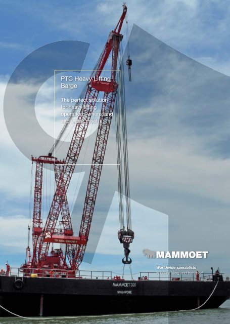
<strong>PTC</strong> <strong>Heavy</strong> <strong>Lifting</strong><br />
<strong>Barge</strong><br />
The perfect solution<br />
for heavy lifting<br />
operations where land<br />
and water meet<br />
Worldwide specialists<br />
in heavy lifting and transport
<strong>PTC</strong> <strong>Heavy</strong> <strong>Lifting</strong> <strong>Barge</strong><br />
<strong>Heavy</strong> lifting for marine projects<br />
<strong>Heavy</strong> lifting operations for harbor and offshore projects are usually carried out using either sheerlegs or<br />
fl oating cranes. Sheerlegs have the advantage of a greater lifting capacity, while fl oating cranes can<br />
revolve (slew) which gives much greater operational fl exibility.<br />
Flexibility<br />
Mammoet has developed its <strong>PTC</strong> cranes over 15 years and used them for 17,000 heavy lifts. We have<br />
now installed one of these <strong>PTC</strong>s on a large barge. The key advantage of our design is that the <strong>PTC</strong> can<br />
operate either with the boom fi xed in sheerlegs mode, for the highest lifting capacity, or in revolving<br />
mode, for much greater fl exibility when picking up and placing the load. The barge has a relatively<br />
shallow draught and can therefore operate close to the shore, even in harbors which have not been fully<br />
dredged.<br />
This multifunctional design can bring great time-savings when constructing large jetties, other harbor<br />
works and offshore structures. The <strong>PTC</strong> on a barge has many advantages over large sheerlegs, fl oating<br />
cranes and jack-up rigs.<br />
<strong>PTC</strong><br />
Mammoet’s <strong>PTC</strong> cranes, developed in-house, have established a reputation for reliably and safely<br />
handling the heaviest loads. Their A-frame jibs are extremely stable and resist side loads. The crane<br />
installed on the barge has specially upgraded slewing drives so that it can rotate (slew) with a load on<br />
the hook even when the barge has an incline up to three degrees. The ballasting of the barge does not<br />
have to be changed during lifting operations, this makes the work safer, quicker and more effi cient.<br />
Operating modes<br />
In slewing (revolving) mode the whole <strong>PTC</strong> can rotate a full circle. This movement is relatively quick<br />
(around 15 minutes for a typical movement of half a circle). Compared with using conventional sheerlegs,<br />
the slewing mode greatly helps to simplify lifting operations and save time.<br />
In sheerlegs mode the upper carrier of the <strong>PTC</strong> is fi xed and the slewing system is not used. Both the<br />
<strong>PTC</strong>’s ballast and the barge itself act as counterweights. This mode provides the highest crane capacity.<br />
Finally, the tie-down mode is used during sea voyages. In this mode the crane is fully secured for safe<br />
transit.<br />
2 | 3
Key parameters<br />
Net lifting capacity:<br />
Sheerlegs mode 974 tons at 20 meters radius 173 tons at 76 meters radius<br />
Slewing mode 267 tons at 20 meters radius 10 tons at 60 meters radius<br />
The net lifting capacity takes account of the weight of the main and auxiliary hook blocks and wire ropes<br />
and is therefore fully available for lifting loads. The auxiliary hoist has a capacity of 30 tons.<br />
<strong>Barge</strong>: 100 x 30 meters, draught with maximum load on the hook 4.2 meters<br />
Maximum hook height (main hoist) 64 meters<br />
Operating envelope<br />
The <strong>PTC</strong> on the barge has a wide operating envelope and can continue lifting up to:<br />
- 12.86 m/s wind speed<br />
- 0.6 m signifi cant wave height<br />
The full lift capacity is available within this envelope, i.e. there is no derating. Certain lifting jobs can be<br />
undertaken at signifi cant wave heights up to 1.3 meters. However, when the operating boundaries are<br />
approached Mammoet personnel on site will assess the situation and decide if the lifting operations may<br />
be continued.
Operational effi ciency<br />
The main hoist operates at a full load speed of 1.8 meters per minute. The 30 ton capacity auxiliary hoist<br />
runs at 18 meters per minute. The slewing (rotation) and luffi ng (boom up/down) speeds are also high<br />
for a crane of this size. The <strong>PTC</strong> is fi tted with two diesel-powered hydraulic powerpacks. This ensures<br />
that a lift can be fi nished even when one powerpack fails.<br />
The barge with the <strong>PTC</strong> is towed to the work site by tugs. Once on site it is relocated by warping<br />
winches, while a tug is kept on stand-by for safety reasons.<br />
Applications<br />
• Construction of large jetties<br />
• General harbor construction operations<br />
• Nearshore heavy lifting operations<br />
4 | 5<br />
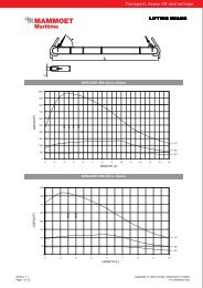
BARGE E331<br />
<strong>PTC</strong> IV ON BARGE<br />
TIE DOWN MODE<br />
<strong>PTC</strong> IV ON BARGE<br />
SHEER LEG MODE<br />
<strong>PTC</strong> IV ON BARGE<br />
REVOLVING MODE<br />
BARGE E331 BARGE E331<br />
Bow
Crane Geometry:<br />
Indication A: Load Table for Sheerleg Mode<br />
Crane Confi guration SSL Sheerleg Mode<br />
Crane Duty Normal<br />
Head Duty Type <strong>Heavy</strong> [1600t]<br />
A-frame length [m] 67.2<br />
A-frame Maximum Angle [ø] 81.54<br />
Hsig & Maximum Period T 1m & 6s / 0.6m & 8.5s<br />
Superballast usage Stays Fixed to Deck and Fixed Ballast with a Triangle Spreader<br />
Capacity Deck Stays [t] 900<br />
Fixed Ballast on Ring [t] 380t at 11.83 [m]: 320 [t] lower ballast & 60t tray mass [lower and upper]<br />
Backmast Radius [m] 13.486 [m]<br />
Windspeed 12.86 [m/s]<br />
Max. Pitch [deg] 0.5<br />
Max. Roll [deg] 2<br />
Static Trim [deg] 0.5<br />
Static Heel [deg] 0.5<br />
Fhoist 1.1<br />
Fduty 1.05<br />
Sideload [deg] 2.5<br />
Offl load [deg] 1<br />
Auxiliary Hoist Max. Capacity [t] 30<br />
Reeving [-] 3<br />
Max sidelead [deg] 4<br />
Max offl ead [deg] 7<br />
Load Capacity Table<br />
Radius SWL<br />
Aframe<br />
Angle<br />
Notes<br />
• The mainboom is composed according to sketch (copied from in drawing<br />
A05-66000-14-01A)<br />
• Crane designed according: DIN 15018part1,3, DIN 15019part2, DIN<br />
15020part1 and DIN 1055part4<br />
• <strong>Lifting</strong> capacity for lifting on barge according to Lloyds Register of<br />
Shipping [code for lifting appliances in a marine environment January<br />
2003]<br />
• Weight of lower blocks, hoisting wire,slings, spreaders, aux. hoist, etc., is<br />
considered as part of the load.<br />
• The lifting capacity is only valid when the main-hoist is reeved according<br />
to the table<br />
• The weight of the ballast trays is counted as ballastweight.<br />
• Interpolation of working loads between radii is allowed.<br />
• Combined lifting of main hoist and auxiliary hoist is not allowed<br />
• The maximum sidelead of 4 degrees for the auxiliary hoist may not be<br />
6 | 7<br />
Height Reeving<br />
Minimum<br />
Required<br />
tugger<br />
capacity<br />
cross<br />
direction of<br />
the crane<br />
Minimum<br />
Required<br />
tugger<br />
capacity<br />
longitudonaldirection<br />
of the<br />
crane<br />
Minimum<br />
Required<br />
resultant<br />
tugger<br />
capacity<br />
[m] [t] [deg] [m] [-] [t] [t] [t]<br />
20 1017 81.54 71.42 22 44.4 17.7 47.8<br />
21 992 80.67 71.25 22 43.3 17.3 46.6<br />
22 969 79.81 71.07 22 42.3 16.9 45.5<br />
23 947 78.94 70.86 22 41.3 16.5 44.5<br />
24 926 78.07 70.65 22 40.4 16.2 43.5<br />
25 906 77.19 70.41 22 39.5 15.8 42.6<br />
26 886 76.31 70.16 22 38.6 15.5 41.6<br />
27 868 75.43 69.89 22 37.9 15.1 40.8<br />
28 850 74.54 69.61 22 37.1 14.8 39.9<br />
29 833 73.65 69.31 22 36.3 14.5 39.1<br />
30 817 72.76 68.99 22 35.6 14.3 38.4<br />
31 801 71.86 68.67 22 34.9 14.0 37.6<br />
32 786 70.95 68.31 22 34.3 13.7 36.9<br />
33 771 70.05 67.94 22 33.6 13.5 36.2<br />
34 758 69.14 67.56 22 33.1 13.2 35.6<br />
35 744 68.21 67.15 22 32.5 13.0 35.0<br />
36 732 67.29 66.72 22 31.9 12.8 34.4<br />
37 719 66.36 66.28 22 31.4 12.5 33.8<br />
38 707 65.42 65.82 22 30.8 12.3 33.2<br />
39 695 64.47 65.33 22 30.3 12.1 32.7<br />
40 684 63.51 64.83 22 29.8 11.9 32.1<br />
41 674 62.55 64.3 22 29.4 11.8 31.7<br />
42 663 61.58 63.75 22 28.9 11.6 31.1<br />
43 652 60.6 63.18 22 28.4 11.4 30.6<br />
44 643 59.61 62.59 22 28.0 11.2 30.2<br />
45 630 58.61 61.97 22 27.5 11.0 29.6<br />
46 612 57.59 61.33 22 26.7 10.7 28.8<br />
47 594 56.57 60.66 22 25.9 10.4 27.9<br />
48 576 55.53 59.97 22 25.1 10.1 27.1<br />
49 560 54.48 59.25 22 24.4 9.8 26.3<br />
50 544 53.42 58.5 22 23.7 9.5 25.6<br />
51 530 52.34 57.72 22 23.1 9.2 24.9<br />
52 516 51.24 56.92 22 22.5 9.0 24.2<br />
53 502 50.12 56.07 22 21.9 8.8 23.6<br />
54 489 49 55.2 22 21.3 8.5 23.0<br />
55 477 47.84 54.28 22 20.8 8.3 22.4<br />
56 465 46.67 53.34 22 20.3 8.1 21.8<br />
57 454 45.46 52.34 22 19.8 7.9 21.3<br />
58 443 44.23 51.31 22 19.3 7.7 20.8<br />
59 432 42.99 50.24 22 18.8 7.5 20.3<br />
60 422 41.7 49.1 22 18.4 7.4 19.8<br />
61 413 40.39 47.93 22 18.0 7.2 19.4<br />
62 404 39.03 46.69 22 17.6 7.1 19.0<br />
63 395 37.63 45.39 22 17.2 6.9 18.6<br />
64 387 36.18 44.01 22 16.9 6.8 18.2<br />
65 378 34.68 42.56 22 16.5 6.6 17.8<br />
66 369 33.13 41.04 22 16.1 6.4 17.3<br />
67 357 31.5 39.42 22 15.6 6.2 16.8<br />
68 343 29.79 37.67 22 15.0 6.0 16.1<br />
69 329 27.98 35.8 22 14.4 5.7 15.5<br />
70 316 26.04 33.76 22 13.8 5.5 14.8<br />
71 302 23.98 31.56 22 13.2 5.3 14.2<br />
72 288 21.69 29.07 22 12.6 5.0 13.5<br />
73 273 19.16 26.27 22 11.9 4.8 12.8<br />
74 258 16.23 22.98 22 11.3 4.5 12.1<br />
75 240 12.63 18.87 22 10.5 4.2 11.3<br />
76 216 7.29 12.69 22 9.4 3.8 10.1<br />
76.43 187 0 4.16 22 8.2 3.3 8.8<br />
exceeded; this will cause the wire to run out of the sheave<br />
• Tugger capacity Fcross is calculated by SWLxsin(2.5) [SWLxsin(heel +<br />
roll)]<br />
• Tugger capacity Flong is calculated by SWLxsin(1) [SWLxsin(trim+ pitch)]<br />
• Tugger capacity to be determined by √((SWLxsin(heel + roll)) 2 +<br />
(SWLxsin(trim + pitch)) 2 )<br />
• The minimum required resultant tugger capacity does NOT include the<br />
tugger angles; the capacity of the tugger should be higher than stated<br />
• The A-bock tackle [einzieh-werk] is to be tensioned to approximately 30t
Crane Geometry:<br />
Indication B: Load Table for Full Revolving Mode<br />
Crane Confi guration SSL Full Revolving Mode<br />
Crane Duty Normal<br />
Head Duty Type <strong>Heavy</strong> [1600t]<br />
A-frame length [m] 67.2<br />
A-frame Maximum Angle [ø] 81.54<br />
Hsig & Maximum Period T 1m & 6s / 0.6m & 8.5s<br />
Superballast usage Fixed Ballast at 11.83m<br />
Fixed Ballast on Ring [t] 380t at 11.83 [m]: 320 [t] lower ballast & 60t tray mass [lower and upper]<br />
Backmast Radius [m] 11.83 [m]<br />
Windspeed 12.86 [m/s]<br />
Max. Pitch [deg] 0.5<br />
Max. Roll [deg] 2<br />
Static Trim [deg] 0.5<br />
Static Heel [deg] 1<br />
Fhoist 1.1<br />
Fduty 1.1<br />
Sideload [deg] 3 / 1<br />
Offl load [deg] 1 / 3<br />
Auxiliary Hoist Max. Capacity [t] 30<br />
Reeving [-] 3<br />
Max sidelead [deg] 4<br />
Max offl ead [deg] 7<br />
Load Capacity Table<br />
Radius SWL<br />
Aframe<br />
Angle<br />
Height Reeving<br />
Minimum<br />
Required<br />
tugger<br />
capacity<br />
in cross or<br />
longi<br />
tudonal<br />
direction of<br />
the crane<br />
Advice<br />
Minimum<br />
Required<br />
tugger<br />
capacity in<br />
longitudo<br />
nal or cross<br />
direction of<br />
the crane<br />
Minimum<br />
Required<br />
Resultant<br />
tugger<br />
capacity<br />
[m] [t] [deg] [m] [-] [t] [t] [t]<br />
20 310 81.54 71.42 22 16.2 5.4 17.1<br />
21 296 80.67 71.25 22 15.5 5.2 16.3<br />
22 282 79.81 71.07 22 14.8 4.9 15.6<br />
23 268 78.94 70.86 22 14.0 4.7 14.8<br />
24 254 78.07 70.65 22 13.3 4.4 14.0<br />
25 240 77.19 70.41 22 12.6 4.2 13.2<br />
26 230 76.31 70.16 22 12.0 4.0 12.7<br />
27 220 75.43 69.89 22 11.5 3.8 12.1<br />
28 210 74.54 69.61 22 11.0 3.7 11.6<br />
29 200 73.65 69.31 22 10.5 3.5 11.0<br />
30 190 72.76 68.99 22 9.9 3.3 10.5<br />
31 182 71.86 68.67 22 9.5 3.2 10.0<br />
32 174 70.95 68.31 22 9.1 3.0 9.6<br />
33 166 70.05 67.94 22 8.7 2.9 9.2<br />
34 158 69.14 67.56 22 8.3 2.8 8.7<br />
35 150 68.21 67.15 22 7.9 2.6 8.3<br />
36 144 67.29 66.72 22 7.5 2.5 7.9<br />
37 138 66.36 66.28 22 7.2 2.4 7.6<br />
38 132 65.42 65.82 22 6.9 2.3 7.3<br />
39 126 64.47 65.33 22 6.6 2.2 7.0<br />
40 120 63.51 64.83 22 6.3 2.1 6.6<br />
41 116 62.55 64.3 22 6.1 2.0 6.4<br />
42 111 61.58 63.75 22 5.8 1.9 6.1<br />
43 107 60.6 63.18 22 5.6 1.9 5.9<br />
44 102 59.61 62.59 22 5.4 1.8 5.6<br />
45 98 58.61 61.97 22 5.1 1.7 5.4<br />
46 94 57.59 61.33 22 4.9 1.6 5.2<br />
47 91 56.57 60.66 22 4.8 1.6 5.0<br />
48 87 55.53 59.97 22 4.6 1.5 4.8<br />
49 84 54.48 59.25 22 4.4 1.5 4.6<br />
50 80 53.42 58.5 22 4.2 1.4 4.4<br />
51 77 52.34 57.72 22 4.0 1.3 4.2<br />
52 74 51.24 56.92 22 3.9 1.3 4.1<br />
53 71 50.12 56.07 22 3.7 1.2 3.9<br />
54 68 49 55.2 22 3.6 1.2 3.8<br />
55 65 47.84 54.28 22 3.4 1.1 3.6<br />
56 63 46.67 53.34 22 3.3 1.1 3.5<br />
57 60 45.46 52.34 22 3.2 1.1 3.3<br />
58 58 44.23 51.31 22 3.0 1.0 3.2<br />
59 55 42.99 50.24 22 2.9 1.0 3.1<br />
60 53 41.7 49.1 22 2.8 0.9 2.9<br />
61 51 40.39 47.93 22 2.6 0.9 2.8<br />
62 48 39.03 46.69 22 2.5 0.8 2.7<br />
63 46 37.63 45.39 22 2.4 0.8 2.5<br />
64 43 36.18 44.01 22 2.3 0.8 2.4<br />
65 41 34.68 42.56 22 2.1 0.7 2.3<br />
66 - 33.13 41.04 22 - - -<br />
67 - 31.5 39.42 22 - - -<br />
68 - 29.79 37.67 22 - - -<br />
69 - 27.98 35.8 22 - - -<br />
70 - 26.04 33.76 22 - - -<br />
71 - 23.98 31.56 22 - - -<br />
72 - 21.69 29.07 22 - - -<br />
73 - 19.16 26.27 22 - - -<br />
74 - 16.23 22.98 22 - - -<br />
75 - 12.63 18.87 22 - - -<br />
76 - 7.29 12.69 22 - - -<br />
76.43 - 0 4.16 22 - - -<br />
Notes<br />
• When the crane is in perpendicular position with the barge it is not<br />
possible to reach a radius larger than 65m, however when the crane is<br />
positioned parallel with the barge, the boom can reach a maximum radius<br />
of 76.43m, or be laid down in the boomrest.<br />
• The mainboom is composed according to sketch (copied from in drawing<br />
A05-66000-14-01A)<br />
• Crane designed according: DIN 15018part1,3, DIN 15019part2, DIN<br />
15020part1 and DIN 1055part4<br />
• <strong>Lifting</strong> capacity for lifting on barge according to Lloyds Register of<br />
Shipping [code for lifting appliances in a marine environment January<br />
2003]<br />
• Weight of lower blocks, hoisting wire,slings, spreaders, aux. hoist, etc., is<br />
considered as part of the load.<br />
• The lifting capacity is only valid when the main-hoist is reeved according<br />
to the table<br />
• The weight of the ballast trays is counted as ballastweight.<br />
• Interpolation of working loads between radii is allowed.<br />
• Combined lifting of main hoist and auxiliary hoist is not allowed<br />
• The maximum sidelead of 4 degrees for the auxiliary hoist may not be<br />
exceeded; this will cause the wire to run out of the sheave<br />
• Advised Tugger capacity Fcross or Flong is calculated by SWLxSIN(3)<br />
[SWLxSIN(heel + roll)]<br />
• Advised Tugger capacity Flong or Fcross is calculated by SWLxSIN(1)<br />
[SWLxSIN(trim+ pitch)]<br />
• Advised Tugger capacity to be determined by √((SWLxSIN(heel + roll)) 2 +<br />
(SWLxSIN(trim + pitch)) 2 )<br />
• The minimum required resultant tugger capacity does NOT include the<br />
tugger angles; the capacity of the tugger should be higher than stated<br />
• The A-bock tackle [einzieh-werk] is to be tensioned to approximately 30t
Worldwide specialists<br />
in heavy lifting and transport<br />
www.mammoet.com<br />
Mammoet (S) Pte Ltd<br />
7 Clementi Loop<br />
Singapore 129811<br />
Telephone: +65 6861 1638<br />
Fax: +65 6861 2718