Model 511 Operators Manual - Krohn-Hite Corporation
Model 511 Operators Manual - Krohn-Hite Corporation
Model 511 Operators Manual - Krohn-Hite Corporation

Create successful ePaper yourself
Turn your PDF publications into a flip-book with our unique Google optimized e-Paper software.
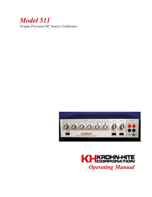
<strong>Model</strong> <strong>511</strong><br />
10 ppm Precision DC Source/ Calibrator<br />
Operating <strong>Manual</strong>.
<strong>Model</strong> <strong>511</strong><br />
10 ppm Precision DC Source/ Calibrator<br />
Operating <strong>Manual</strong><br />
Unit 4 15 Jonathan Drive, Brockton, MA 02301-5566<br />
Tel: (508) 580-1660, Fax: (508) 583-8989<br />
www.krohn-hite.com, e-mail info@krohnhite.com<br />
Printed in U.S.A.<br />
Version 1.05<br />
Revised April 2003<br />
Copyright © 2003 <strong>Krohn</strong>-<strong>Hite</strong> <strong>Corporation</strong> All rights reserved. No part of this publication may<br />
be reproduced, stored in a retrieval system or transmitted in any form by any means, electronic,<br />
mechanical photocopying, recording, or otherwise, without the prior written permission of<br />
<strong>Krohn</strong>-<strong>Hite</strong> <strong>Corporation</strong><br />
Information furnished in this manual is believed to be accurate and reliable. However, no responsibility is<br />
assumed by <strong>Krohn</strong>-<strong>Hite</strong> <strong>Corporation</strong> for its use; nor for any infringements of patents or other rights of<br />
third parties which may result from its use.
Table of Contents<br />
Section Title Page<br />
1 General Description and Specifications................................................................... 1-1<br />
1-1. Introduction ............................................................................................... 1-1<br />
1-2. Description ................................................................................................ 1-1<br />
1-3. Safety Information..................................................................................... 1-2<br />
1-4. <strong>Krohn</strong>-<strong>Hite</strong> Contact Information ............................................................... 1-3<br />
1-5. Factory Calibration.................................................................................... 1-3<br />
1-6. Specifications ............................................................................................ 1-4<br />
1-7. Output Specifications ............................................................................. 1-4<br />
1-8. Secondary Performance Specifications .................................................. 1-4<br />
1-9. General Specifications............................................................................ 1-5<br />
1-10. Options ................................................................................................... 1-6<br />
2 Operation ................................................................................................................... 2-1<br />
2-1. Introduction ............................................................................................... 2-1<br />
2-2 Unpacking.................................................................................................. 2-1<br />
2-3 Power Requirements.................................................................................. 2-2<br />
2-4 Front Panel................................................................................................. 2-2<br />
2-4-1 Front panel controls .................................................................. 2-2<br />
2-4-2 Front panel indicators ................................................................ 2-3<br />
2-4-3 Output Terminals ...................................................................... 2-3<br />
2-5 Rear Panel.................................................................................................. 2-4<br />
2-5-1 AC Power Entry Module ........................................................... 2-4<br />
2-5-2 Optional Output Terminals ........................................................ 2-7<br />
3 Incoming Acceptance ............................................................................................... 3-1<br />
3-1. Introduction ............................................................................................... 3-1<br />
3-2. Recommended Test Equipment.............................................................. 3-1<br />
3-3. Warm-up Procedure................................................................................ 3-2<br />
3-4. DC Voltage Verification Test.................................................................... 3-2<br />
3-5. Optional Tests............................................................................................ 3-3<br />
3-6. DC Voltage Load Regulation Test ......................................................... 3-3<br />
3-7. DC Voltage Output Noise Test............................................................... 3-4<br />
i
<strong>Model</strong> <strong>511</strong><br />
Operating <strong>Manual</strong><br />
List of Illustrations<br />
Section Title Page<br />
2 Operation ...................................................................................................................<br />
2-1. <strong>511</strong> Front Panel View.................................................................................2-2<br />
2-2. Front Output Terminals..............................................................................2-3<br />
2-3. <strong>511</strong> Rear Panel View..................................................................................2-4<br />
2-4. 120 Volt Line Setting Example..................................................................2-4<br />
2-5. Power Entry Module Exploded View ........................................................2-6<br />
2-6. Optional Rear Output Terminals ................................................................2-7<br />
3 Incoming Acceptance .................................................................................................<br />
3-1. Load Regulation Setup...............................................................................3-3<br />
3-2. Noise Check Setup .....................................................................................3-5<br />
List of Tables<br />
Section Title Page<br />
1 General Description and Specifications ...................................................................<br />
1-1. Output Specifications .................................................................................1-4<br />
3 Incoming Acceptance .................................................................................................<br />
3-1. Output Uncertainty Check..........................................................................3-2<br />
NOTE:<br />
Errata and addendum (if any) will appear in the back of this manual<br />
ii
Section 1<br />
Introduction and Specifications<br />
1-1 Introduction<br />
This manual provides the user with the information needed to operate the <strong>Krohn</strong>-<strong>Hite</strong><br />
<strong>Model</strong> <strong>511</strong>. Section 3 is a procedure used to verify that the DC Calibrator is within the<br />
published specifications. Calibration information is included in the <strong>Krohn</strong>-<strong>Hite</strong> <strong>Model</strong><br />
<strong>511</strong> Calibration manual. Details for contacting <strong>Krohn</strong>-<strong>Hite</strong> and important safety<br />
information are also contained within this manual.<br />
Note: If the <strong>Model</strong> <strong>511</strong> is still under warranty and it is outside its specified limits,<br />
contact <strong>Krohn</strong>-<strong>Hite</strong> or your distributor to establish the course of action.<br />
1-2 Description<br />
The <strong>Model</strong> <strong>511</strong> DC Voltage Source / Calibrator is a highly versatile reference source,<br />
designed to meet the needs of computer systems, production line testing, QC and QA<br />
departments, design labs, and standards laboratories. The instrument has specified<br />
accuracies traceable to the U. S. National Institute of Standards and Technology.<br />
The <strong>Model</strong> <strong>511</strong> includes a "crowbar"or short circuit of the output and a true bipolar<br />
output stage that can be floated 500 volts from chassis. Output and sense terminals are<br />
gold plated, low thermal, safety, type, whose sense connection is selected via a front<br />
panel 2 wire - 4 wire sense switch, that negates the need for using cumbersome shorting<br />
links.<br />
Resolution of each range is 1 part per million. The instrument is a highly accurate<br />
reference that can be used for calibration of digital voltmeters, analog meters,<br />
semiconductor analyzing systems, analog references for computers, analog-to-digital<br />
converters, telemetry and data acquisition systems, and wherever a stable source is<br />
required.<br />
There are no adjustments made during normal operation. All adjustments are made<br />
during the factory calibration. The circuitry is completely solid state made of discrete,<br />
hybrid and/or integrated circuits packaged on etched glass circuit boards. These are<br />
proven circuits, using derated components to insure long life and maximum reliability.<br />
The instrument is overload and short-circuit protected, and is fully operational in normal<br />
environmental conditions. The <strong>511</strong> will drive a short circuit indefinitely without damage<br />
to the instrument, and will recover to rated specifications in less than 100µs.<br />
1-1
<strong>Model</strong> <strong>511</strong><br />
Operating <strong>Manual</strong><br />
1-3 Safety Information<br />
The <strong>Model</strong> <strong>511</strong> has been designed, tested and supplied in a safe condition. The following<br />
general safety precautions must be observed during all phases of operation, service, and<br />
repair. Failure to comply with these precautions or with specific warnings elsewhere in<br />
this manual violates safety standards of design, manufacture and intended use of this<br />
instrument. <strong>Krohn</strong>-<strong>Hite</strong> assumes no liability for the customer's failure to comply with<br />
these requirements.<br />
This manual contains information and warnings that must be observed to keep the<br />
instrument in a safe condition and ensure safe operation. Operation or service in<br />
conditions or in a manner other than specified could compromise safety. For the correct<br />
and safe use of this instrument, operating and service personnel must follow generally<br />
accepted safety procedures.<br />
To avoid injury or fire hazard, do not switch on the instrument if it is damaged or<br />
suspected to be faulty. Do not use the instrument in damp, wet, condensing, dusty or<br />
explosive gas environments.<br />
Whenever it is likely that safety protection has been impaired, make the instrument<br />
inoperative and secure against any unintended operation, and then inform qualified<br />
personnel. Safety protection is likely to be impaired if, for example, the instrument<br />
shows visible damage, or fails to operate normally.<br />
Ground the Instrument<br />
To minimize shock hazard, the instrument chassis and cabinet must be connected to an<br />
electrical ground. Any interruption of the protective ground conductor inside or outside<br />
the instrument is likely to make the instrument dangerous. Intentional interruption is<br />
prohibited.<br />
Do Not Operate In an Explosive Atmosphere<br />
Do not operate the instrument in the presence of flammable gases or fumes. Operation of<br />
any electrical instrument in such an environment constitutes a definite safety hazard.<br />
Keep Away From Live Circuits<br />
Operating personnel must not remove instrument covers. Qualified maintenance<br />
personnel must make component replacement and internal adjustments. Under certain<br />
conditions, dangerous voltages may exist. To avoid injuries, always disconnect input<br />
voltages before removing the covers. Use caution when working with voltages above 30<br />
Vac rms, 42 V peak, or 60 Vdc. These voltages pose a shock hazard A good safety<br />
practice is to expect that hazardous voltage is present in any unknown circuit before<br />
measuring.<br />
1-2
General Description and Specifications<br />
Safety Information<br />
Do Not Substitute Parts or Modify Instrument<br />
Because of the danger of introducing additional hazards, do not install substitute parts or<br />
perform any unauthorized modifications. Use only the replacement fuse(s) listed in this<br />
manual. Return the unit to the <strong>Krohn</strong>-<strong>Hite</strong> Service Department to modify or repair the<br />
instrument to ensure that safety features are maintained.<br />
Do Not Operate a Damaged Instrument<br />
Whenever it is possible that the safety protection features built into this instrument have<br />
been impaired, either through physical damage, excessive moisture, or any other reason,<br />
REMOVE the POWER and do not use the instrument until safe operation can be verified<br />
by service-trained personnel. If necessary, return the instrument to the <strong>Krohn</strong>-<strong>Hite</strong><br />
Service Department for service and repair to ensure that the safety features are<br />
maintained.<br />
1-4 <strong>Krohn</strong>-<strong>Hite</strong> Contact Information<br />
To order parts, accessories, or obtain service call:<br />
1-508-580-1660<br />
Or, visit the <strong>Krohn</strong>-<strong>Hite</strong> Web site at www.krohn-hite.com<br />
1-5 Factory Calibration<br />
When manufactured, all <strong>511</strong>’s are aged, calibrated and thoroughly verified with test<br />
equipment and calibration standards that are traceable to the U.S. National Bureau of<br />
Standards. Included with each shipment is a certificate of calibration.<br />
A performance verification procedure is provided in section three. This procedure can be<br />
used to make certain that the calibrator is with-in specifications. Verification is usually<br />
preformed when you first take delivery of the calibrator to make sure that there was no<br />
shipping damage, when you have questions about the calibrator’s accuracy, or after<br />
calibration<br />
<strong>Krohn</strong>-<strong>Hite</strong> <strong>Corporation</strong> recommends that the <strong>Model</strong> <strong>511</strong> be calibrated yearly at <strong>Krohn</strong>-<br />
<strong>Hite</strong>’s service center to sustain factory new performance. All calibrators returned to the<br />
factory for calibration have pre and post calibration data recorded. This allows a<br />
performance history file to be complied for each unit. Minor updates are installed (if any<br />
are available) during recalibration<br />
1-3
<strong>Model</strong> <strong>511</strong><br />
Operating <strong>Manual</strong><br />
1-6 Specifications<br />
Prior to shipment, the <strong>Model</strong> <strong>511</strong> calibrators are calibrated and data is recorded to<br />
guarantee that the unit is operating with-in specifications. Output Specifications listed<br />
below are absolute accuracies and are traceability to N.I.S.T.<br />
1-7 Output Specifications<br />
The output uncertainty specifications apply after a one hour warm-up under standard<br />
reference conditions of 23ºC ± 1ºC and
General Description and Specifications<br />
Secondary Performance Specifications<br />
Output Impedance:<br />
10 µΩ.<br />
Line Regulation:<br />
± (1ppm of range +1 µV) for a ± 10 % line fluctuation.<br />
Load Regulation:<br />
± 1µV no load to full load.<br />
Settling Time:<br />
< than 100ms to settle to within 5ppm of final value.<br />
1-9 General Specifications<br />
Calibration Interval:<br />
1 year for 10ppm accuracy.<br />
Warm-up Time:<br />
1 hour to rated accuracy.<br />
Output Isolation:<br />
Output may be floated 500V from chassis<br />
Power Requirements:<br />
105-125 or 210-250 Volts ac, single phase, 50-400 Hz, 20 watts max.<br />
Temperature:<br />
Calibration Temperature: 23ºC ±1ºC<br />
Operating Limit: 0ºC to 50ºC 2<br />
Storage Temperature: -40ºC to 85ºC<br />
Dimension:<br />
3.5"(9cm) high, 14"(36cm) wide, 12.5"(32.1cm) deep.<br />
Weight:<br />
12 lbs(5.4kg) net; 14 lbs(6.3kg) shipping.<br />
Certification:<br />
A Certificate of Compliance is issued with each new instrument to certify the calibration<br />
traceable to the National Institute of Standards and Technology (N.I.S.T.).<br />
2 Accuracy is derated above 40º C due to loss of oven control.<br />
1-5
<strong>Model</strong> <strong>511</strong><br />
Operating <strong>Manual</strong><br />
Warranty:<br />
Full one year warranty on parts and labor and a full one year warranty on specifications<br />
and performance.<br />
Extended warranty:<br />
Part No. EW<strong>511</strong> provides an additional one year to the standard warranty<br />
1-10 Options<br />
Rack Mount Kit:<br />
Part number RK-314 permits installation of the model <strong>511</strong> into a standard 19" rack.<br />
Rear Output Terminals:<br />
Option 003 provides both front and rear output terminals. Note that only one set of output<br />
terminals may be used at one time.<br />
CE Output Terminals:<br />
Option 004 Provides CE safety type output terminals.<br />
1-6
Section 2<br />
Operation<br />
2-1 Introduction<br />
This section describes the basic operation of the <strong>Model</strong> <strong>511</strong>. It includes the proper ac<br />
power requirements along with details of all operating modes and any special features. .<br />
----- Warning -----<br />
The chassis of this instrument is connected to ground. For safety<br />
purposes, connect the line cord to a grounded 3-terminal ac outlet.<br />
The information in this section is intended only for qualified service<br />
personnel Do not attempt these procedures unless you are qualified to<br />
do so.<br />
----- Caution -----<br />
Because of the potentially dangerous voltages that exist within the<br />
instrument, the covers of the <strong>Model</strong> <strong>511</strong> should not be removed when<br />
connected to an ac power source.<br />
The <strong>Model</strong> <strong>511</strong> is adjusted and checked carefully before shipment to ensure that the unit<br />
meets all specifications. It is aged and final tested to ensure that it is ready for use. The<br />
unit is shipped complete.<br />
2-2 Unpacking<br />
Unpack the <strong>Model</strong> <strong>511</strong> carefully and inspect it for any damage that may have occurred<br />
during shipment. Check the case for damage, and check for loose sub-assemblies and<br />
parts.<br />
2-1
<strong>Model</strong> <strong>511</strong><br />
Operating <strong>Manual</strong><br />
2-3 Power Requirements<br />
The <strong>Model</strong> <strong>511</strong> is designed to operate from a single phase, 50-60Hz ac power source of<br />
105V-132V or 210V-250V. The ac Power Entry Module, located on the rear panel,<br />
contains the main line fuse, an input line voltage selector, and an EMI filter. A<br />
detachable, 3-wire line cord is provided with the instrument. The <strong>511</strong> is normally shipped<br />
configured to the proper line voltage. To change settings, refer to section 2.5.1 for<br />
instructions.<br />
2-4 Front Panel<br />
Figure 2.1 <strong>511</strong> Front Panel View<br />
2-4-1 Front Panel Controls<br />
Power switch: A two position switch supplies power to the <strong>Model</strong> <strong>511</strong>.<br />
“Sense” Switch: This switch has two positions. In the "2 Wire" position, only the<br />
instrument's output terminals are connected, the sense terminals are connected to the<br />
output terminals internally. This position is used with high impedance loads. In the "4<br />
Wire" position the user must connect both the sense and output terminals together at the<br />
load. This position is used to prevent "IR" wiring losses when drawing current.<br />
"Lo" switch: This switch has two positions. In the "Float" position the low output<br />
terminal is floating from chassis. In the "Chassis" position the low output terminal is<br />
connected to chassis ground.<br />
Decade Switches: There are six. Each one controls one decade of output magnitude, and<br />
is selectable from 0 to 10.<br />
Range Switch: A three position switch selecting one of the three voltage ranges: 100<br />
mV, 1 V, or 10 V.<br />
2-2
Operation<br />
Front Panel Controls<br />
Polarity Switch: This switch also has three positions. "+" polarity denotes that the red<br />
output terminal is positive with respect to black output terminal, and vice versa for "-"<br />
polarity. The "0" position produces a "crowbar" or short circuit "0" at the output<br />
terminals.<br />
2-4-2 Front Panel Indicators<br />
Power On Indicator: The Green led is on whenever the <strong>511</strong> is plugged into an AC power<br />
source and the power switch is in the on position.<br />
Decimal Point Indicators: A "floating" decimal point is illuminated by several yellow<br />
LEDs and properly locates the decimal point for the range indicated.<br />
Overload Indicator: When illuminated, indicates an overload or possibly shorted<br />
condition (excessive current draw), or an open sense circuit condition.<br />
2-4-3 Output Terminals<br />
Front Panel Connections: There are five terminals located on the front panel. All<br />
terminals are low thermal, gold plated type. Spacing is the standard 3/4" centers.<br />
Connections are located as follows:<br />
HIGH SENSE → ← HIGH OUTPUT<br />
LOW SENSE → ← LOW OUTPUT<br />
← CASE GROUND<br />
Figure 2.2 Front Output Terminals<br />
The "output" and "sense" refers to the 4-wire remote sense capability. This 4-wire system<br />
eliminates the IR drop and thus maintains the voltage accuracy, of the <strong>Model</strong> <strong>511</strong>.<br />
NOTE: The "sense" circuit must be connected to the<br />
load when the <strong>511</strong> is used in 4-wire mode.<br />
2-3
<strong>Model</strong> <strong>511</strong><br />
Operating <strong>Manual</strong><br />
2-5 Rear Panel<br />
Figure 2.3 <strong>511</strong> Rear Panel View<br />
2-5-1 Power Entry Module<br />
The <strong>511</strong> will operate on 100, 120, 220 or 240 Vac line voltage. The following explain<br />
how to change the voltage settings and the fuse. The cover of the Power Entry Module<br />
shows four possible voltage settings (100V, 120V, 220V or 240V). Notice that a pin will<br />
be in one of these holes, indicating the present voltage setting for the <strong>511</strong>. If this setting<br />
does not match the voltage available at your site, then it must be changed before<br />
powering on the <strong>511</strong>. Figure 2.4 shows an example setting for 120 Vac operation.<br />
Figure 2.4 120 Volt Line Setting Example<br />
Follow the steps below to change a fuse or convert the operating voltage of a <strong>511</strong>.<br />
2-4
Operation<br />
Power Entry Module<br />
Set the <strong>511</strong> power switch to OFF. Unplug the power cord from the ac wall outlet and<br />
from the power cord receptacle on the power entry module. Refer to Figure 2-5 on the<br />
next page.<br />
Using a small flat blade screwdriver or similar tool inserted into the slot at the left edge<br />
of the cover, carefully pry the cover off the fuse cavity. To change the voltage setting,<br />
grasp the white plastic voltage select board pin and pull straight outward until the voltage<br />
select board unseats from the power entry module. Hold the board so that you can read<br />
the four voltage selection labels (100, 120, 220 and 240) imprinted on the board. Move<br />
the voltage indicator pin to the opposite side of the board from the desired voltage label.<br />
Be sure to seat the pin in the notch provided on the board's edge. Install the voltage<br />
select board so that it is fully seated in the voltage select cavity (the label side toward the<br />
fuse cavity).<br />
To change the fuse (s), remove the fuse (s) from the fuse carrier on the back of the cover.<br />
For 100 or 120 Vac operation, the fuse rating is 1/8 Amp, Slow-Blow. For 220 or 240<br />
Vac operation, the fuse rating is 1/16 Amp, Slow-Blow. Be sure to use the correct rating<br />
for your voltage selection. For installation, insert the fuse(s) of the proper rating into the<br />
fuse carrier. To change the fuse arrangement to match that used in your country, remove<br />
the screw from the fuse carrier, remove the fuse carrier, turn the fuse carrier so that the<br />
desired fuse arrangement (single fuse or dual fuses) is facing outward, install the fuse<br />
carrier, and install the screw. For United States type power operation, use a single<br />
standard AGC or 3AG 0.25 inch x 1.25 inches fuse of the correct rating. For European<br />
type power operation, use two standard 5.2 mm x 20 mm fuses of the correct rating. For<br />
European use, is important to note that if your local electrical code does not allow a dual<br />
fuse arrangement, then a dummy fuse must be installed in the lower fuse carrier.<br />
Otherwise, the <strong>511</strong> will not operate. Place the cover on the power entry module and press<br />
inward until it snaps into place. Verify that the desired operating voltage is indicated with<br />
the voltage select board pin on the cover label. Connect the power cord to the power<br />
entry module and wall outlet.<br />
The <strong>Model</strong> <strong>511</strong> is now ready to be operated on the selected ac line voltage.<br />
2-5
<strong>Model</strong> <strong>511</strong><br />
Operating <strong>Manual</strong><br />
Figure 2.5 Power Entry Module<br />
2-6
Operation<br />
Optional Output terminals<br />
2-5-2 Optional Output Terminals<br />
Rear Panel Connections: A factory installed option, there are five terminals located on the<br />
rear panel. The configuration is the same as the front panel terminals. Figure 2.6 below<br />
shows the connections.<br />
NOTE: Only one set of output terminals may be used at one time.<br />
HIGH OUTPUT → ← HIGH SENSE<br />
LOW OUTPUT →<br />
← LOW SENSE<br />
CASE GROUND →<br />
Figure 2.6 Optional Rear Output Terminals<br />
2-7
<strong>Model</strong> <strong>511</strong><br />
Operating <strong>Manual</strong><br />
Notes:<br />
2-8
Section 3<br />
Incoming Acceptance<br />
3-1 Introduction<br />
The following procedure should be used to verify that the <strong>Model</strong> <strong>511</strong> is operating properly. These<br />
checks may be used for incoming acceptance and periodic performance checks. Test should be<br />
made with the covers in place and after a one hour warm-up under standard reference conditions<br />
of 23ºC ± 1ºC and
<strong>Model</strong> <strong>511</strong><br />
Operating <strong>Manual</strong><br />
3-3 Warm-up Procedure<br />
Perform your verification measurements in a test environment that has a stable ambient<br />
room temperature with a relative humidity of less than 70% unless noted otherwise. The<br />
<strong>Model</strong> <strong>511</strong> requires a power line voltage of 100V, 120V, 220V, 240V, ±10% with a line<br />
frequency of 50Hz to 400Hz<br />
Allow the minimum warm up time for all test equipment. The <strong>Model</strong> <strong>511</strong> needs at least<br />
one hour to stabilize. Additional time will be needed if the instrument has been subjected<br />
to temperatures outside the 18-28°C range.<br />
3-4 DC Voltage Verification Test<br />
After allowing sufficient warm up time, connect the DC voltmeter to the output terminals<br />
of the model <strong>511</strong>. The front panel “SENSE” switch should be in the 2-wire position and<br />
the “LO” switch should be in the float positions. The chart below lists the <strong>511</strong> settings<br />
along with the test limits.<br />
Uncertainty Check<br />
Range<br />
D.P.<br />
LED<br />
on<br />
Polarity<br />
Front Panel Decade<br />
Switch Setting Low Limit Upper Limit<br />
10V<br />
V<br />
+ 10 0 0 0 0 0 + 9.999858 V +10.000142 V<br />
- 10 0 0 0 0 0 - 9.999858 V -10.000142 V<br />
+ or - 0 0 0 0 0 0 ± 42 µV<br />
+ 10 0 0 0 0 0 + 0.999984 V + 1.000016 V<br />
1V 0.V<br />
- 10 0 0 0 0 0 - 0.999984 V - 1.000016 V<br />
100mV<br />
mV<br />
+ or - 0 0 0 0 0 0 ± 6 µV<br />
+ 10 0 0 0 0 0 + 99.997 mV + 100.003 mV<br />
- 10 0 0 0 0 0 - 99.997 mV - 100.003 mV<br />
+ or - 0 0 0 0 0 0 ± 2 µV<br />
Table 3.1 Output Uncertainty Check<br />
3-2
Verification<br />
Optional Tests<br />
3-5 Optional Tests<br />
These procedures are used to ensure that the <strong>Model</strong> <strong>511</strong> passes both the 4-wire load<br />
regulation and the output noise tests.<br />
3-6 DC Voltage Load Regulation Test<br />
Connect the DC voltmeter to the sense and output junction on the Power Load Resistor<br />
box. 3 Set the <strong>511</strong> to 4-wire mode and connect the load box to the <strong>511</strong> with two 2-wire<br />
twisted pair cables. The <strong>511</strong> sense and output terminals must be connected at the load<br />
box. Refer to figure 2.1 for hookup details.<br />
<strong>Model</strong> <strong>511</strong><br />
Load Box<br />
SENSE OUT<br />
HI<br />
Voltmeter<br />
LO<br />
IN<br />
Figure 3-1 Load Regulation Setup<br />
Set the <strong>511</strong> to output 10.00000 volts and set the load box to a few hundred thousand<br />
ohms (light load). After noting the voltmeters reading, reduce the load resistance to 100<br />
ohms and record the voltmeter new reading. The change should be less than ± 1µV.<br />
Change to the 1 V range and repeat the test using 10 ohms for the second setting. The<br />
change should be less than ± 1µV.<br />
Change to the 100 mV range and repeat the test using 1 ohms for the second setting. The<br />
change should be less than ± 1µV.<br />
3 The voltmeter must be connected to the sense leads at the junction of where the <strong>511</strong>'s output<br />
and sense cables connect at the load.<br />
3-3
<strong>Model</strong> <strong>511</strong><br />
Operating <strong>Manual</strong><br />
3-7 Output Noise Test<br />
KH uses the following procedure to measure the noise levels of the voltage calibrator.<br />
Techniques are employed to minimize external ground loops and radiation paths that may<br />
introduce improper data into the desired measurements. "Rule of Thumb": If the<br />
measurement indicates more than 1 millivolt p-p of noise on any KH instrument, the<br />
operator should recheck his equipment, cables and connections.<br />
Noise may appear in many forms; therefore KH recommends the use of a true rms<br />
voltmeter with a 20mV range and a high gain (1000) differential pre-amplifier to make<br />
the noise measurements. The high gain differential pre-amplifier specified will increase<br />
the sensitivity of the true rms voltmeter, enabling it to resolve noise levels in the µV<br />
level.<br />
The noise test should not be made simultaneously with regulation and voltage accuracy<br />
test. The "feedback" currents from some measuring devices will seriously disturb noise<br />
measurements.<br />
Differential input measurements are the most reliable. They will cancel out common<br />
mode, due to slight errors in cable connections.<br />
The pre-amplifier, true rms voltmeter and the KH Calibrator under test should be<br />
connected to adjacent power outlets on the same phase. A three wire ground is required.<br />
In the event the line does not have a ground, the pre-amplifier and unit under test should<br />
have a separate, heavy wire chassis-to-chassis connection separate from the shield of the<br />
differential input leads. The lead used between the pre-amplifier input and the source<br />
output should be a shield, twisted pair with the shield connected to the frame of the preamplifier,<br />
and to the chassis ground terminal adjacent to the output terminals of the KH<br />
source. Do not use the shield of the input cable as the chassis-to-chassis connection in<br />
place of line system ground. Use additional separate heavy wire. Refer to Figure 2.2 on<br />
the next page for correct connections.<br />
3-4
Verification<br />
Output Noise Tests<br />
<strong>Model</strong> <strong>511</strong><br />
Pre-amplifier<br />
SENSE<br />
OUT<br />
+<br />
Input<br />
-<br />
Output<br />
Voltmeter<br />
CHASSIS<br />
IN<br />
Figure 3.2 Noise Check Setup<br />
Set the differential pre-amplifier upper frequency cutoff to100kHz and the lower cutoff to<br />
0.1Hz. Set the model <strong>511</strong> “sense” switch to the “2-Wire” position and the output to zero.<br />
Connect the output of the pre-amplifier to the input of the true rms voltmeter. Observe<br />
that ripple and noise do not exceed specifications on each of the ranges. The limit is 5µV<br />
rms on both the 100mV and 1V range; and 10µV rms on the 10V range.<br />
NOTE: The "DC" mode on the preamp in use usually results in more accurate<br />
"noise" measurements. Be aware of the specifications for your preamp if this test is<br />
made at voltage levels other than zero, and AC input is used.<br />
3-5
<strong>Model</strong> <strong>511</strong><br />
Operating <strong>Manual</strong><br />
Notes:<br />
3-6