Download - Hitachi Power Europe GmbH
Download - Hitachi Power Europe GmbH
Download - Hitachi Power Europe GmbH

Create successful ePaper yourself
Turn your PDF publications into a flip-book with our unique Google optimized e-Paper software.
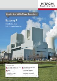
Solid Fuel Firing Systems<br />
and Components
<strong>Hitachi</strong> <strong>Power</strong> <strong>Europe</strong><br />
From Coal to Electricity<br />
d<br />
b<br />
f<br />
c<br />
e<br />
a<br />
Generation of electricity in a typical coal power plant<br />
Contents<br />
<strong>Hitachi</strong> <strong>Power</strong> <strong>Europe</strong> 2<br />
Selection Criteria 5<br />
Furnace 6<br />
Mill Feeders 8<br />
Pulverizers 10<br />
Pulverized Fuel Burners 14<br />
Burn-Out Grate 20<br />
Ash Removal Systems 21<br />
Replacement Parts Service 23<br />
A Before being injected into the furnace, the raw coal is crushed down to a fine pulverized form<br />
in the coal mills.<br />
2 Flue gases up to 1,450 °C arise from pulverized fuel combustion in the steam generator furnace.<br />
The liberated heat is used to generate high-pressure and high-temperature steam.<br />
3 The steam is directed to a turbine; it flows onto the blade wheels and turns the turbine shaft.<br />
An attached generator then generates the electrical power.<br />
4 With the help of catalysts, the nitrogen oxides in the flue gas react in the DeNO x system<br />
to produce nitrogen and water vapor.<br />
5 Ash particles adhere to electrically-charged surfaces in the electrostatic precipitator;<br />
they are rapped and removed from the flue gas.<br />
6 In the flue gas desulphurization system (FGD) lime slurry or suspended pulverized limestone<br />
bind the sulphur dioxide coming from the flue gas. The final product arising is gypsum.<br />
2
Technology Leader with Excellent References<br />
Whether as a plant constructor or as a supplier of key components, <strong>Hitachi</strong> <strong>Power</strong> <strong>Europe</strong><br />
<strong>GmbH</strong> (HPE) is one of the technology and market leaders in fossil-fired power plants.<br />
The company – a subsidiary of <strong>Hitachi</strong>, Ltd. – has its head offices in Duisburg. HPE designs<br />
and builds not only power plants but also supplies all the key components such as utility<br />
steam generators, environmental engineering, turbines and pulverizers. In so doing, HPE can<br />
turn back to a track record going back over many years, an extensive list of references and<br />
to the outstanding know-how of its workforce. Within the <strong>Hitachi</strong> Group, HPE is responsible<br />
for the markets in <strong>Europe</strong>, Africa, Russia (incl. Belarus) and India.<br />
<strong>Hitachi</strong> <strong>Power</strong> <strong>Europe</strong> <strong>GmbH</strong>, Duisburg<br />
Babcock Fertigungszentrum <strong>GmbH</strong>, Oberhausen<br />
BGR Boilers Private Ltd., Chennai<br />
Donges SteelTec <strong>GmbH</strong>, Darmstadt<br />
1 2<br />
6<br />
4<br />
7<br />
<strong>Hitachi</strong> <strong>Power</strong> Africa (Pty) Ltd., Johannesburg<br />
<strong>Hitachi</strong> <strong>Power</strong> <strong>Europe</strong> Service <strong>GmbH</strong>, Duisburg<br />
Meeraner Dampfkesselbau <strong>GmbH</strong>, Meerane<br />
3<br />
5<br />
Coal Firing Systems 3
Firing Systems and Components<br />
Ensuring Economic Efficiency, Conserving Resources<br />
As one of the global cutting-edge companies in power plant design and construction,<br />
<strong>Hitachi</strong> <strong>Power</strong> <strong>Europe</strong> provides highly advanced firing systems which can be used in their<br />
entirety or as single components for practically all fossil fuel qualities.<br />
Project Country Kunde MW Fuel Order obtained<br />
Niederaußem Germany RWE Energie AG 1 x 1,012 Lignite 1995<br />
Boxberg Q Germany VEAG 1 x 907 Lignite 1995<br />
Elbistan B Turkey TEAS 4 x 360 Lignite 1998<br />
Dezhou 5 / 6 China CNTIC 2 x 660 Anthrazit 1998<br />
Hamborn Germany RWE Energie AG 1 x 260 Blast Furnace Gas 1999<br />
Iskenderun Turkey Siemens / STEAG 2 x 660 Hard Coal 2000<br />
Neurath F & G Germany RWE Rheinbraun AG 2 x 1,100 Lignite 2003<br />
Baosteel China Baoshan Iron & Steel Co. Ltd 1 x 350<br />
Blast Furnace Gas, Coke<br />
Oven Gas, Heavy Fuel Oil<br />
2005<br />
Boxberg R Germany Vattenfall <strong>Europe</strong> 1 x 670 Lignite 2005<br />
Walsum 10 Germany Evonik 1 x 790 Hard Coal 2006<br />
Moorburg A / B Germany Vattenfall <strong>Europe</strong> 2 x 820 Hard Coal 2006<br />
Datteln Germany E.ON Kraftwerke 1 x 1,100 Hard Coal 2006<br />
Gent Belgium Electrabel 1 x 300 Blast Furnace Gas 2006<br />
Medupi South Africa Eskom 6 x 790 Hard Coal 2007<br />
Maasvlakte Netherlands E.ON Kraftwerke 1 x 1,100 Hard Coal 2008<br />
Wilhelmshaven Germany Electrabel 1 x 750 Hard Coal 2008<br />
Kusile Südafrika Eskom 6 x 790 Hard Coal 2008<br />
Rotterdam South Africa Electrabel 1 x 790 Hard Coal 2008<br />
Maja India NTPC 2 x 660 Hard Coal 2012<br />
Solapur India NTPC 2 x 660 Hard Coal 2012<br />
Raghunathpur India NTPC 2 x 660 Hard Coal 2012<br />
Kozienice Poland Enea 1 x 1,000 Hard Coal 2012<br />
Selection of steam generator orders since 1995<br />
HPE develops solutions, which are just as flexible as our customers’ requirements, for energy<br />
suppliers and industry alike. This can be seen most clearly from the large number of different<br />
types of references (see table) available. A high degree of operational efficiency and conservation<br />
of resources /environment is looked upon as an obligation and challenge by HPE in<br />
designing and manufacturing new utility steam generators. This also applies to the modernization<br />
and enhancement of existing power plants and their components, such as pulverizers<br />
and burners.<br />
It goes without saying that HPE as a certificated DIN ISO 9001 company always orientates<br />
itself to the best possible quality.<br />
4
What Counts is the Choice<br />
The planning and design of firing systems is primarily dependent on the fuel used and<br />
must be individually tailored – something requiring above-average achievements on the<br />
part of our designers.<br />
Whilst there is no secret about up-to-date firing systems, one still needs considerable<br />
know-how and a long track record in plant concepts and specific sequences. Playing a prime<br />
role here are the fuel properties themselves, such as calorific value, moisture and ash content,<br />
volatiles and coal grindability.<br />
Advanced firing systems with a staged combustion sequence lower emissions and require<br />
substantial design and material selection outlay on the basis of the standards and legislation<br />
in force. This applies equally to the selection and construction of the firing components.<br />
Tangential firing system<br />
Slag-tap firing system<br />
Cyclone firing system<br />
U/double U firing system<br />
Hard coal<br />
Dry bottom ash<br />
firing system<br />
Normal volatile coal<br />
Low volatile coal<br />
Front firing system<br />
Double front firing system<br />
Opposed firing system<br />
Corner firing system<br />
Double front firing system<br />
Opposed firing system<br />
Lignite<br />
Dry bottom ash<br />
firing system<br />
Direct firing system<br />
Direct firing system<br />
with vapor separation<br />
Direct firing system<br />
with vapor recycling<br />
Biomass<br />
Dry bottom ash<br />
firing system<br />
Direct firing system<br />
Indirect firing system<br />
Coal Firing Systems 5
Furnace<br />
Pulverized Hard Coal Firing System<br />
The principal features are:<br />
■■<br />
Uniform liberation of heat<br />
■■<br />
Low nitrogen oxide emissions<br />
coupled with practically a total<br />
fuel transformation<br />
■■<br />
Oxygen-rich flue gas atmosphere<br />
right next to the boiler tube walls<br />
Fossil-fired power plants are currently enjoying a boom across the world. And hard coals,<br />
in particular, can be widely used for energy transformation purposes.<br />
The decision to design a firing system with dry bottom ash removal or as a slag-tap furnace<br />
largely depends on the fuel properties themselves. Volatile matter, ash content and chemical<br />
ash composition have always been of decisive significance.<br />
The decision-making process was simplified with the launching of innovative DS ® burners<br />
followed by tremendous combustion stability. Modern steam generators are usually designed<br />
today solely as dry ash discharging boiler plants at low cost and high efficiencies. This applies<br />
to practically the entire range of fuels irrespective of their effects from high volatile bituminous<br />
coal to anthracite.<br />
For many years now, the linear arrangement as front, double-front or opposed firing equipment<br />
complete with vertically offset burner levels has proved to be the most suitable system<br />
for pulverized hard coal firing systems.<br />
The clear arrangement of mill and burner level ensures that the highly complex systems are<br />
clearly designed and arranged. This, in turn, creates a high degree of accessibility and ease<br />
of maintenance.<br />
CAD model of the Datteln 4<br />
utility steam generator<br />
■■<br />
1 x 1,100 MWel / 1 x 2,939 t/h<br />
■■<br />
Benson ® Steam generator<br />
■■<br />
Hard coal<br />
■■<br />
Steam parameters:<br />
Superheated steam: 600 °C / 305 bar;<br />
Reheater: 620 °C / 78 bar<br />
■■<br />
Entering into service: 2011<br />
■■<br />
Scope of delivery:<br />
Utility steam generator including<br />
all the related components, engineering,<br />
installation and commissioning<br />
6
Pulverized Lignite Firing System<br />
Combustion systems for lignite operated steam generators can be designed as direct<br />
systems for the use of raw lignite or as combined systems using raw and pre-dried lignite<br />
in the same furnace.<br />
Even with the usage of very high ash lignites, the new HPE lignite swirl burners (RS ® burners)<br />
do not need any vapor separation.<br />
The excellent igniting stability of the RS ® burners allows the burners to be arranged in a<br />
different way at the combustion chamber – for instance in the form of an all-wall firing system.<br />
Such a system combines the benefits of linear firing equipment with those of a tangential<br />
firing system. The firing steps alone enable the 200 mg/m 3 NO x standard to be undercut in<br />
RS ® burners. As a result, there is no need for complex, multiple air-staging concepts for<br />
adherence to the NO x standards.<br />
The stable ignition of RS ® burners produces a marked improvement in the percentage load<br />
operations of lignite firing systems. Even with problematical fuels, the excess stoichiometric<br />
operation of these burners has a positive effect on fouling and slagging and it optimally<br />
protects the evaporator tube walls from corrosive flue gas products.<br />
The future will see boiler plants mainly being planned for the use of dry pulverized lignite with<br />
interim storage.<br />
CAD model of the Boxberg R<br />
utility steam generator<br />
■■<br />
1 x 670 MWel / 1 x 1,710 t/h<br />
■■<br />
Benson ® Steam generator<br />
■■<br />
Lignite<br />
■■<br />
Steam parameters:<br />
Superheated steam: 600 °C / 315 bar;<br />
Reheater: 610 °C / 72 bar<br />
■■<br />
Entering into service: 2010 / 2011<br />
■■<br />
Scope of delivery:<br />
Utility steam generator including<br />
all the related components, engineering,<br />
installation and placing into service<br />
Coal Firing Systems 7
Mill Feeders<br />
Belt conveyor<br />
Reliability even under Demanding Requirements<br />
Designed as coal bunker dischargers, the mill feeders supply the pulverizers with raw coal –<br />
evenly dosed and in keeping with boiler load requirements.<br />
Even under very demanding requirements, the <strong>Hitachi</strong> <strong>Power</strong> <strong>Europe</strong> designed mill feeders<br />
operate both reliably and safely.<br />
Experienced HPE staff establish the optimum feeder in keeping with the requested fuel quantity,<br />
design directives (including DIN EN 12952-9, NFPA 85 F) and customer requirements<br />
(for instance, volumetric and gravimetric metering).<br />
Other selection factors are the various bulk material properties, such as coal flow and erosion<br />
behavior. The belt speed is determined by the quantity conveyed. Purge air is supplied to the<br />
housing to stop condensate forming and, in turn, to stop corrosion.<br />
8
In hard coal boiler units, belt conveyors are used to discharge the raw coal from the<br />
bunker. In lignite plants, drag-chain conveyors together with belt conveyors are used to<br />
discharge the raw coal from the bunker.<br />
Belt conveyor<br />
The belt conveyor with corrugated edge belt ensures high outputs, uniform bunker discharge<br />
and continuous mill charging – even under low conveying rates. This design permits volumetric<br />
/ gravimetric metering and quantities conveyed of up to 120 t/h. Conveyed material falling<br />
to the bottom of the feeder is transferred to the coal downcomer by the simultaneously running<br />
scraper chain.<br />
Raw coal<br />
d<br />
a<br />
g<br />
A Bed depth limiter<br />
B Belt drive station<br />
b<br />
h<br />
c<br />
C Belt tensioning station<br />
D Corrugated edge belt<br />
E Scraper chain<br />
F Lower belt supporting roller<br />
e<br />
f<br />
G Bunker shut off gate<br />
H Conveyor-type weigher (optional)<br />
Drag-chain conveyor<br />
Drag-chain conveyors are meant for limited conveyed quantities of up to approx. 40 t/h –<br />
this can, in special cases, be raised to 70 t/h. The fuel is discharged opposite to the direction<br />
of conveying. The drag-chain conveyor principle allows both a compact design with minimum<br />
spacing between bunker discharge and conveyor dumping as well as a possible large<br />
spacing between material charging and dumping.<br />
Raw coal<br />
e<br />
a<br />
d<br />
b<br />
c<br />
A Bed depth limiter<br />
B Belt drive station<br />
C Tensioning station<br />
D Forged fork link chain<br />
E Bunker shut off gate<br />
Coal Firing Systems 9
Pulverizers<br />
Excellent Results<br />
In the mills, the raw coal is simultaneously pulverized, dried and evenly distributed to the<br />
coal burners. Hot air or flue gases transfer the pulverized fuel to the burner and reduce the<br />
moisture in the coal.<br />
MPS ® Mill<br />
MPS ® Bowl & Roller Mill<br />
The MPS ® bowl & roller mill from <strong>Hitachi</strong> <strong>Power</strong> <strong>Europe</strong> grinds and dries hard coals and<br />
difficult-to-grind lignite with a low moisture content to pulverized fuel and distributes them<br />
evenly directly to the burners.<br />
Various-sized mills for throughputs ranging from 10 t/h to 200 t/h can be supplied. Constant<br />
refinements and impro vements have led to excellent crushing results with high fineness<br />
a<br />
b<br />
grades from raw coal found throughout the world. The positive operating<br />
properties and low energy requirements have contribu ted in no small<br />
measure to the success of these mills.<br />
c<br />
e<br />
g<br />
f<br />
d<br />
A Rotary classifier<br />
B Classifier drive<br />
C Grinding rollers<br />
E Grinding table<br />
F Gear<br />
G Motor<br />
D Hydro-pneumatic system<br />
10
Long Service Life<br />
RKD Mill<br />
RKD Tube Ball Mill<br />
The <strong>Hitachi</strong> <strong>Power</strong> <strong>Europe</strong> RKD tube ball mill grinds and dries difficult-to-pulverize hard coals<br />
(particularly low-volatile coals such as lean coal and anthracite). This mill type can deal with<br />
approx. 150 t /h of coal. Depending on size and space, the tube ball mill can be designed<br />
with drum or neck bearing and be of the single or double pass type.<br />
a<br />
g<br />
b<br />
d<br />
e<br />
c<br />
f<br />
A Rotary classifier<br />
B Oversize return<br />
C Neck bearing<br />
D Drive gear rim<br />
E Grinding ball filling<br />
F Feed spiral conveyor<br />
G Classifier riser<br />
Coal Firing Systems 11
Pulverizers<br />
Low Energy Requirements<br />
Pulverizing lignite is particularly challenging in view of its high moisture content and the<br />
considerable throughputs involved. Here again <strong>Hitachi</strong> <strong>Power</strong> <strong>Europe</strong> has the right products<br />
in this segment.<br />
DGS ® Mill<br />
DGS ® Integral Fan Distributor and Beater Mill<br />
HPE supplies DGS ® mills of various sizes up to a 180 t/h throughput for drying and pulverizing<br />
raw lignite and brown coals with a high moisture content.<br />
DGS ® technology involves the raw coal and flue gases being initially put through the precrushing<br />
beater section of the beater wheel. This ensures excellent air and coal dust distribution<br />
into the beater wheel. Crushing in the DGS ® mill is usually so<br />
intensive that adequate grinding fineness can be obtained in one<br />
a<br />
working operation – without the need of an additional classifier.<br />
c<br />
This both raises the pressure balance and cuts back on energy<br />
f g<br />
b<br />
g<br />
d<br />
requirements. The DGS ® mill has stood the test of time particularly<br />
with difficult-to-work lignites – something that explains<br />
its considerable lifetime and unrivalled properties.<br />
e<br />
A Flue gas gate valve<br />
B Inlet housing<br />
C Beater shaft<br />
D Beater wheel<br />
E Coupling<br />
F Motor<br />
G Bearing<br />
12
Easy Maintenance<br />
NV Mill<br />
NV Wet Coal Fan Mill<br />
The NV mills ranging from 10 t/h to 140 t/h throu ghputs are for crushing high moisture<br />
content lignites for direct injection into the furnace.<br />
Together with the flue gases, the raw lignite is brought for crushing purposes into the beater<br />
wheel. It acts as a fan impeller fitted with beater plates. Baffle-type classifiers ensure that the<br />
a<br />
e<br />
required fuel fineness for combustion is fulfilled.<br />
The high-tech NV mill more than meets the ongoing demands<br />
worldwide of operational availability and low costs.<br />
f<br />
g<br />
b<br />
c<br />
d<br />
A Gate valve housing<br />
B Grinding chamber door<br />
C Grinding chamber<br />
D Beater wheel<br />
E Baffle-type classifier<br />
F Double bearing<br />
G Motor<br />
Coal Firing Systems 13
Pulverized Fuel Burners<br />
Optimum Combustion<br />
How do you lower NO x emissions and at the same time control as many different fuels as<br />
possible Questions like these are today determining the concept of pulverized fuel firing<br />
systems and burners.<br />
DS ® Burners<br />
300<br />
1,800<br />
1,667 1,697<br />
260<br />
1,607<br />
1,487<br />
1,600<br />
250<br />
1,303<br />
1,400<br />
200<br />
1,095 1,119 1,135 1,165<br />
1,200<br />
184<br />
144<br />
859<br />
1,000<br />
150<br />
879 9591,031 787<br />
138<br />
120 120<br />
800<br />
643<br />
120<br />
100<br />
88<br />
600<br />
383<br />
80<br />
72 72<br />
64<br />
46<br />
60 400<br />
263<br />
50<br />
8 9 9 129<br />
175<br />
20<br />
24<br />
16 30 30<br />
200<br />
8 1 0<br />
0 0 0<br />
0 0<br />
1991 1993 1995 1997 1999 2001 2003 2005 2007 2009 2011 2013 2015<br />
n Total number n Year of commissioning<br />
DS ® burners were introduced early in the 1990s and continuously developed over the years.<br />
The burner’s principle is focused on fuel treatment to prepare the particles for the pyrolysis<br />
and ignition process that follows. The characteristic features of this burner type are expressed<br />
by the definition of initiation and course of ignition.<br />
Ignition = Pyrolysis + Oxidation<br />
This type of burner with a concentric design and swirled flow streams in all sections, has its<br />
field of application mostly in direct firing systems using all kinds of pulverized fuels.<br />
The DS ® burner concept utilizes operating experience from more than 1,100 applications.<br />
Pulverized Fuel<br />
Core Air<br />
Secondary Air Tertiary Air<br />
Adjustable<br />
Swirlers<br />
Fuel Nozzle<br />
Igniter<br />
14
DS ® burners with an operating range of 1: 3,5 are available for direct operated combustion<br />
systems in a range of thermal capacities from 20 to 100 MW.<br />
Fuels<br />
Burner Classes (MW thermal capacity)<br />
20 40 60 80 100<br />
Lignite* x x x<br />
Sub-bituminous coal x x x x<br />
Bituminous coal x x x x x<br />
Anthracite x x x<br />
Biomass (co-firing with coal) x x x x<br />
Biomass (standalone) x x<br />
* Pulverizer operation on air basis<br />
DS ® burner design for a windbox arrangement<br />
Basically developed for bituminous coal, these burners are applicable now for all carbon<br />
containing solid fuels like anthracite, sub-bituminous coal, lignite and biomass of different<br />
structures. The DS ® burner is suitable for applications with individual air control as well as for<br />
the use in common windboxes.<br />
Coal Firing Systems 15
Pulverized Fuel Burners<br />
DST Burner<br />
The DST burner has been developed on the basis of the DS ® burner concept for use in<br />
indirect firing systems.<br />
Core Gas Secondary Gas Tertiary Gas<br />
Pulverized Fuel<br />
Oil Lance<br />
Swirler<br />
Fuel Nozzle<br />
This burner type is the right one for pre-dried pulverized fuels like anthracite, bituminous and<br />
sub-bituminous coal, lignite, peat, biomass of various types as well as further carbon-containing<br />
pulverized fuels separately or in any combination. Dust loading can range from 0.5 up<br />
to 15 kg fuel / kg medium.<br />
DST burners can be used for atmospheric operation or in pressurized systems with air and / or<br />
oxyfuel atmosphere.<br />
Air, inert gas and flue gas with or without oxygen enrichment can be used as the transport<br />
medium for the fuel.<br />
DST burners can be operated with a turndown rate up to 1:17. As a result a boiler can be<br />
operated from lowest start-up load up to full load conditions with an unlimited load response<br />
rate. Due to an extremely high PF / PA ratio the NO x emission rate is rapidly reduced.<br />
DST burners are available for thermal capacities from 20 to 60 MW for all kinds of pre-dried<br />
pulverized fuels used in indirect firing systems.<br />
Fuels<br />
(pre-dried & pulverized)<br />
Burner Classes (MW thermal capacity)<br />
20 40 60<br />
Lignite x x x<br />
Sub-bituminous coal x x x<br />
Bituminous coal x x x<br />
Anthracite x x x<br />
Biomass (standalone) x x x<br />
16
DS ® burner direct (left)<br />
DST burner indirect (right)<br />
Comparison of both burner systems<br />
5<br />
Coal / PA Ratio [kg/kg]<br />
4<br />
3<br />
2<br />
1<br />
0<br />
Burner control range (as tested)<br />
Indirect firing system, DST burner<br />
Indirect firing system, DST burner<br />
Direct firing system, DS ® burner<br />
minimum load range<br />
0 5 10 15 20 25 30 35 40 45<br />
Burner capacity [MW]<br />
Energy storage and plant flexibility are the main challenges of power generation in the future.<br />
With the DST burner control range of 1:17 coal firing systems will be best prepared to meet<br />
the resulting operating demands.<br />
Coal Firing Systems 17
M<br />
M<br />
M<br />
M<br />
M<br />
M<br />
M<br />
M<br />
M<br />
M<br />
M<br />
M<br />
Pulverized Fuel Burners<br />
DST Burner<br />
Combined firing system<br />
M<br />
M<br />
100 %<br />
75 %<br />
M 20 M 40 M 30 M 10<br />
50 %<br />
M M M M<br />
M<br />
25 %<br />
Flexible Load Range<br />
0 %<br />
Flexibility is what is demanded of power generation now and in the future. With development<br />
of the DST burner, flexible concepts using indirect firing systems are now becoming the focus<br />
of interest.<br />
This system offers lots of advantages like:<br />
■■Turn down of investment and operating costs<br />
■■Independency of mill and boiler operation<br />
■■Wide load range with all burners in service<br />
■■Quick response in case of high load change demand<br />
■■Boiler operation without supplementary fuel (oil/ gas) – even for start-up<br />
■■Exact definition of burner air ratios that enable boiler excess air below 10 %<br />
The combined firing system using the advantages of the direct and indirect systems is the<br />
consequential answer to the fascinating questions surrounding coal fired power plants in<br />
facing the challenges of the future.<br />
18
RS ® Burner<br />
70 160<br />
60<br />
50<br />
40<br />
30<br />
20<br />
10<br />
0<br />
4<br />
4<br />
4<br />
0<br />
10<br />
6<br />
10<br />
0<br />
16<br />
6<br />
16<br />
48<br />
64<br />
76 76<br />
12<br />
100 100 100 100 100 100 100<br />
0<br />
0 0 0 0 0 0 0 0<br />
1994 1996 1998 2000 2002 2004 2006 2008 2010<br />
24<br />
124<br />
24<br />
124<br />
n Total number n Year of commissioning<br />
142<br />
18<br />
2012<br />
140<br />
120<br />
100<br />
80<br />
60<br />
40<br />
20<br />
0<br />
RS ® Burners<br />
Orders since 1994<br />
The extensive findings acquired from developing DS ® burner technology (flame stability, ignition<br />
as well as air staging in the burner proximate zone) are also available for lignite firing<br />
technology purposes.<br />
What has been developed is the lignite RS ® burner. In contrast to the conventional jet burner,<br />
the RS ® burner permits control of the fuel / air mixture and flame propagation in the burner<br />
proximate zone.<br />
Secondary Air<br />
Radiant<br />
Shielding Pipe<br />
Pulverized Fuel<br />
Cooling Air<br />
Secondary Air Deflecting Cone<br />
Coal Dust<br />
Coal Firing Systems 19
Burn-Out Grate<br />
High Efficiencies<br />
In lignite coal or peat-fired plants with a high proportion of xylitol or fibers in the fuel,<br />
the proportion of unburnt residue in the boiler hopper ash can be extremely high and this<br />
impairs firing efficiency.<br />
Burn-out grate diagram<br />
a<br />
Ash<br />
n b c<br />
f<br />
d<br />
A Boiler furnace hopper<br />
e<br />
B Refractory jacket of retarded<br />
combustion reactor<br />
C Water seal gasket<br />
D Firmly fixed grate supporting bars<br />
g<br />
E Grate carriage<br />
F Grate surface<br />
G Hydraulic system for grate<br />
carriage and deashing flap<br />
H Ash hopper<br />
I Cooling and combustion air<br />
J Deashing flap<br />
i<br />
h<br />
j<br />
k<br />
l<br />
K Ash discharge chute<br />
L Shutoff gate valve in ash<br />
discharge chute<br />
M Deasher<br />
m<br />
N Monitoring system<br />
The optimum designed burn-out grate ensures that the ash burnout in the boiler hopper is<br />
improved to over 80 % – thus substantially raising the overall efficiency of the boiler plant.<br />
In addition, afterburning results in additional heat input into the boiler hopper, which would<br />
otherwise be relatively cold. This leads to an even distribution of temperature in the furnace.<br />
20
➞➞<br />
Ash Removal<br />
Stable in the Extreme and Long Lasting<br />
Ash removal systems have been part of HPE’s range of production and supplies for many<br />
years now. This applies to bottom ash removal as well as to the transfer of ash accumulating<br />
in the course of air heater and electrostatic precipitator ash removal.<br />
Submerged scraper conveyor<br />
Submerged scraper conveyor functions:<br />
■■<br />
Air sealing to the boiler hopper<br />
■■<br />
Ash cooling<br />
■■<br />
Ash conveying<br />
■■<br />
Inlet for furnace inspection<br />
Submerged scraper conveyor for hard coal-fired systems<br />
e<br />
c<br />
a<br />
b<br />
i f<br />
h<br />
1 Bottom ash<br />
i<br />
f<br />
k g j k d k g<br />
Submerged scraper conveyor for lignite-fired systems<br />
c<br />
a<br />
k g j k d k g<br />
k<br />
e<br />
h<br />
2 Transfer chute with immersion piece<br />
3 Expansion joint<br />
4 Submerged scraper conveyor<br />
5 Drive station frequency controlled<br />
6 Tensioning station<br />
7 Idler stations<br />
8 Discharge chute<br />
9 Cooling water inlet<br />
J Overflow<br />
K Travelling rails<br />
Conveying<br />
direction<br />
Coal Firing Systems 21
Other Ash Removal Systems<br />
HPE provides a broad range of ash handling systems. These systems apply to ash handling<br />
for furnace bottom ash removal and also to the ash removal from all downstream ash<br />
accumulation points.<br />
Our systems offer a lot of benefits: they are stable in the extreme, wear parts are long lasting<br />
and both the energy requirements and operating / upkeep costs are low. HPE provides the<br />
entire range for utility steam generators with pulverized hard coal and lignite firing: from design,<br />
manufacturing and erection up to commissioning the complete ash disposal systems<br />
including loading systems for transport by truck, rail and ship.<br />
Ash Removal<br />
Components<br />
Our Other<br />
Ash Removal Systems<br />
■■Ash silos and dewatering bunker<br />
■■Single-strand chain conveyors<br />
■■Apron conveyor<br />
■■Screw conveyors<br />
■■Single and double roller crushers<br />
■■Hammer crushers<br />
■■Rotary feeders<br />
■■Single and double pendulum flap<br />
■■Shut off gates<br />
■■Ejectors<br />
■■Bucket-type conveyors<br />
■■Sluice ways<br />
■■Dry mechanical ash removal systems<br />
■■Hydraulic ash removal systems<br />
■■Pneumatic ash removal systems<br />
■■Mill reject systems<br />
■■Re-cooling systems for submerged<br />
conveyor overflow water<br />
22
Replacement Parts Service<br />
As a designer and manufacturer of original components, HPE is the ideal partner to contact<br />
when modernization or replacement parts are needed.<br />
Our extensive expertise derived from designing and delivering utility steam generators with<br />
the associated components over many years enables our HPE experts to provide professional<br />
solutions matched to customer requirements in the matter of plant design and operations.<br />
Optimized plants ensure that performance and availability are raised and that efficient operations<br />
are attained as far as possible. As a competent and flexible partner, HPE’ expertise is<br />
available in the fields of process engineering, plant optimization, measuring technology, plantinternal<br />
inspection, component installation and commissioning. At the same time, HPE supports<br />
customers in the design and configuration of their future plants – from the technical<br />
point of view (planning, design, optimizing) and in the matter of operating economy analyses.<br />
Rapid Service from<br />
a Competent Partner<br />
Feeders<br />
conveyor<br />
Coal Mills<br />
Burners<br />
Ash submerged<br />
scraper conveyor<br />
Manufacturing from<br />
a single source<br />
Belts<br />
Wear parts<br />
Pulverized fuel<br />
line elbows<br />
Chains<br />
As stakeholder in Babcock Fertigungszentrum<br />
<strong>GmbH</strong> in Oberhau-<br />
Chains Linings Pulverized fuel lines Scraper bars<br />
sen, we are in the closest possible<br />
Drives Nozzle rings Impact plates Wear plates<br />
contact with our partners and, as<br />
such, are flexible and quick in<br />
Bearings Shaft seals Housings Drives<br />
handling your enquiries and can<br />
Gate valves<br />
Conveyor-type<br />
weighers<br />
Feeding screw<br />
conveyors<br />
Beater sections<br />
Adjusting mechanisms<br />
Bearings<br />
provide you with dependable solutions.<br />
More on this under:<br />
www.bfz-ob.de<br />
Expansion joints<br />
Gear units<br />
Drives<br />
Service Hotline: +49.203.8038-2550<br />
Service Fax: +49.203.8038-612550<br />
Email: spareparts@hitachi-power.com<br />
Coal Firing Systems 23
© <strong>Hitachi</strong> <strong>Power</strong> <strong>Europe</strong> <strong>GmbH</strong> / 02.2013 / Printed on chlorine-free bleached paper<br />
<strong>Hitachi</strong> <strong>Power</strong> <strong>Europe</strong> <strong>GmbH</strong><br />
Schifferstraße 80<br />
47059 Duisburg, Germany<br />
Phone +49.203.8038-0<br />
Fax +49.203.8038-1809<br />
infobox@hitachi-power.com<br />
www.hitachi-power.com