SEE-THROUGH WOOD BURNING FIREPLACE - Desa
SEE-THROUGH WOOD BURNING FIREPLACE - Desa
SEE-THROUGH WOOD BURNING FIREPLACE - Desa

Create successful ePaper yourself
Turn your PDF publications into a flip-book with our unique Google optimized e-Paper software.
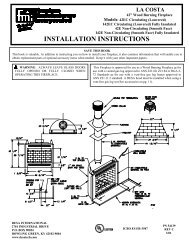
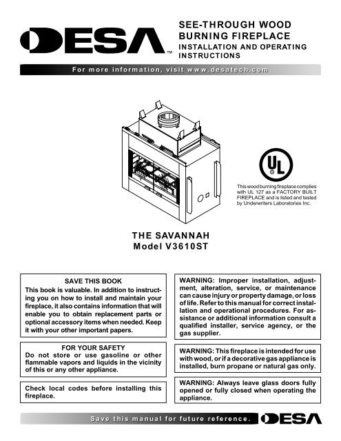
<strong>SEE</strong>-<strong>THROUGH</strong> <strong>WOOD</strong><br />
<strong>BURNING</strong> <strong>FIREPLACE</strong><br />
INSTALLATION AND OPERATING<br />
INSTRUCTIONS<br />
For more information, visit www.desatech.com<br />
This wood burning fireplace complies<br />
with UL 127 as a FACTORY BUILT<br />
<strong>FIREPLACE</strong> and is listed and tested<br />
by Underwriters Laboratories Inc.<br />
THE SAVANNAH<br />
Model V3610ST<br />
SAVE THIS BOOK<br />
This book is valuable. In addition to instructing<br />
you on how to install and maintain your<br />
fireplace, it also contains information that will<br />
enable you to obtain replacement parts or<br />
optional accessory items when needed. Keep<br />
it with your other important papers.<br />
FOR YOUR SAFETY<br />
Do not store or use gasoline or other<br />
flammable vapors and liquids in the vicinity<br />
of this or any other appliance.<br />
Check local codes before installing this<br />
fireplace.<br />
WARNING: Improper installation, adjustment,<br />
alteration, service, or maintenance<br />
can cause injury or property damage, or loss<br />
of life. Refer to this manual for correct installation<br />
and operational procedures. For assistance<br />
or additional information consult a<br />
qualified installer, service agency, or the<br />
gas supplier.<br />
WARNING: This fireplace is intended for use<br />
with wood, or if a decorative gas appliance is<br />
installed, burn propane or natural gas only.<br />
WARNING: Always leave glass doors fully<br />
opened or fully closed when operating the<br />
appliance.<br />
Save this manual for future reference.
2<br />
TABLE OF CONTENTS<br />
PRODUCT DIMENSIONS<br />
TABLE OF CONTENTS<br />
PRODUCT DIMENSIONS ........................................................... 2<br />
INTRODUCTION......................................................................... 3<br />
SAFETY INFORMATION ............................................................ 3<br />
BEFORE YOU BEGIN ................................................................ 3<br />
<strong>FIREPLACE</strong> INSTALLATION ...................................................... 4<br />
OUTSIDE AIR KIT INSTALLATION ............................................. 7<br />
GAS LINE INSTALLATION ......................................................... 7<br />
VENTING INSTALLTION ............................................................ 8<br />
OPERATING GUIDELINES AND MAINTENANCE<br />
INSTRUCTIONS ................................................................. 14<br />
TECHNICAL SERVICE ............................................................. 15<br />
REPLACEMENT AND ACCESSORY PARTS ........................... 16<br />
OWNER'S REGISTRATION FORM .......................................... 17<br />
PRODUCT DIMENSIONS<br />
6"<br />
(15.2cm)<br />
15 3 /8" Dia.<br />
(38.7cm)<br />
O.D.<br />
Top View<br />
10" Dia. I.D.<br />
(25.4cm)<br />
2 1 /2"<br />
(6.3cm)<br />
24"<br />
(60.9cm)<br />
9 1 /2"<br />
(24.1cm)<br />
24"<br />
(60.9cm)<br />
19"<br />
(48.2cm)<br />
4 1 /2"<br />
(11.4cm)<br />
21 5 /16"<br />
(54.1cm)<br />
42 5 /8"<br />
(108.2cm)<br />
15 1 /2"<br />
(39.3cm)<br />
17 3 /16"<br />
(43.6cm)<br />
12"<br />
(30.4cm)<br />
17"<br />
(40.6cm)<br />
Outside Air<br />
1 1 /2"<br />
(3.8cm)<br />
52 3 /4"<br />
(134cm)<br />
Gas Line<br />
Conduit<br />
37 1 /2"<br />
(95.2cm)<br />
20 1 /2"<br />
(52cm)<br />
10 1 /4"<br />
(26cm)<br />
11 1 /4"<br />
(28.5cm)<br />
7"<br />
(177mm)<br />
12"<br />
(304mm)<br />
Left Side View<br />
36 1 /2"<br />
(92.7cm)<br />
Front View<br />
Figure 1 - Product Dimensions<br />
For more information, visit www.desatech.com<br />
55253C
INTRODUCTION<br />
SAFETY INFORMATION<br />
BEFORE YOU BEGIN<br />
3<br />
INTRODUCTION<br />
Model V3610ST series is a wood-burning fireplace intended and<br />
approved for installation in either residential homes or buildings of<br />
standard construction. This fireplace system requires the utilization<br />
of a DESA 10" double wall, snap-lock flue pipe system.<br />
GLASS DOORS are optional with this fireplace and come in<br />
different styles. For further details (see page 14).<br />
BE SURE TO CHECK WITH YOUR LOCAL BUILDING<br />
CODES FOR AREA REQUIREMENTS BEFORE IN-<br />
STALLING THIS <strong>FIREPLACE</strong>.<br />
SAFETY INFORMATION<br />
IMPORTANT: Read this owner’s manual carefully and<br />
completely before trying to assemble, operate, or service<br />
this fireplace. Improper use of this fireplace can cause<br />
serious injury or death from burns, and fire.<br />
1. This fireplace reaches high temperatures. Keep children and<br />
adults away from hot surfaces to avoid burns or clothing ignition.<br />
Fireplace will remain hot for a time after shutdown. Allow<br />
surfaces to cool before touching.<br />
2. Carefully supervise young children when they are in the room<br />
with fireplace.<br />
3. Do not modify this fireplace under any circumstances. Any<br />
parts removed for servicing must be replaced prior to operating<br />
fireplace.<br />
4. Let fireplace cool before servicing, repairing, or installing accessories.<br />
Only a qualified service person should install, service,<br />
or repair this fireplace. Have fireplace inspected annually<br />
by a qualified service person.<br />
5. Keep the area around your fireplace clear of combustible materials,<br />
gasoline, and other flammable vapor and liquids. Do not<br />
operate fireplace where these are used or stored. Do not place<br />
items such as clothing or decorations on or around fireplace.<br />
6. Do not connect this fireplace to a chimney system other than a<br />
DESA chimney system.<br />
7. Due to high temperatures, do not locate this fireplace in high<br />
traffic areas or near furniture and draperies.<br />
8. Provide adequate clearances around air openings into the combustion<br />
chamber. NEVER obstruct the front openings of the<br />
fireplace or the flow of combustion and ventilation air. Install<br />
in an area providing ventilation and adequate combustion air.<br />
BEFORE YOU BEGIN<br />
Before beginning the installation of your fireplace, read these<br />
instructions thoroughly. This DESA fireplace and its approved<br />
components are safe when installed according to this installation<br />
manual, and operated as recommended by DESA. Unless you use<br />
DESA approved components tested for this fireplace, YOU MAY<br />
CAUSE A FIRE HAZARD!<br />
The DESA warranty will be voided by, and DESA disclaims any<br />
responsibility for the following actions:<br />
A) Modification of the fireplace or any of the components manufactured<br />
by DESA unless otherwise permitted in writing by DESA.<br />
B) The use of a fireplace insert or any component part not approved<br />
by DESA in combination with DESA fireplace.<br />
C) Installation and/or operation in a manner other than instructed<br />
in this manual.<br />
D) The burning of any other fuel not tested or approved by DESA<br />
in this wood burning fireplace.<br />
PROPER INSTALLATION is the most important step in ensuring<br />
a safe and continuous operation of this fireplace. Although grounding<br />
may not be required by code in your area, it must be electrically<br />
grounded in accordance with local codes or, in the absence of local<br />
codes, with the National Electrical Code, ANSI/NFPA 70-1990.<br />
This fireplace is intended for installation in accordance with the<br />
National Fire Protection Association Standard for Chimneys, Fireplaces,<br />
Vents and Solid-Fuel Burning Fireplaces, NFPA 211, and in<br />
accordance with codes such as the BOCA Basic /National Code, the<br />
Standard Mechanical Code, and the Uniform Building Code.<br />
THIS <strong>FIREPLACE</strong> IS NOT INTENDED TO BE USED AS<br />
A PRIMARY SOURCE OF HEAT.<br />
NOTE: Installation and repair should be done by a qualified<br />
installer familiar with the fireplace. The fireplace and chimney<br />
system should be inspected and cleaned before use and periodically<br />
thereafter especially during heating season to prevent the excessive<br />
buildup of soot and creosote and to ensure a safe operating system.<br />
For more information, visit www.desatech.com<br />
55253C
4<br />
<strong>FIREPLACE</strong> INSTALLATION<br />
Selecting Location<br />
Clearances<br />
Mantle Clearances<br />
<strong>FIREPLACE</strong> INSTALLATION<br />
SELECTING LOCATION<br />
To determine the safest and most efficient location for your fireplace,<br />
you must take into consideration the following guidelines:<br />
1. The location must allow for all the proper clearances (see Figure<br />
2).<br />
2. Consider a location where the heat output would not be affected<br />
by drafts, air conditioning ducts, windows or doors.<br />
3. A location that avoids the cutting of joists or roof rafters will<br />
make installation easier.<br />
4. If an outside air kit is to be installed, accessibility to outside<br />
combustion air must be considered. This can also be achieved<br />
through a vented crawl space in some cases, for more details<br />
refer to the section on outside air kit installation.<br />
The typical installation for a V3610ST is a projected installation, which<br />
allows you to extend the fireplace any distance into the room. A<br />
projection may be ideal for a new addition on an existing, finished wall.<br />
CLEARANCES<br />
MINIMUM CLEARANCES TO COMBUSTIBLES<br />
Back ............................................. 1" Min.<br />
Adjacent Wall ............................. 12" Min.<br />
Chimney Outer Pipe Surfaces ...... 2" Min.<br />
Bottom Of Fireplaces To Floor ..... 0" Min.<br />
CAUTION: Do not block required air spaces with<br />
insulation or any other material. Do not obstruct<br />
effective opening of fireplace with any type of facing<br />
material. Combustible material must not be in contact<br />
with the black front face of the fireplace.<br />
Figure 2 - Plan View of Common Location<br />
Figure 3 - Fireplace Clearances<br />
MANTLE CLEARANCES<br />
Woodwork, such as wood trims, mantles, and other combustible<br />
materials, should not be placed within 9 inches of the effective<br />
opening of this fireplace.<br />
Combustible material above and projecting more than 1 1 /2 inches<br />
from the fireplace’s front face (see Figure 4, page 5), should not be<br />
placed less than 12 inches from the effective opening of the fireplace<br />
(Ref: NFPA std.7-3.3.3.).<br />
Mantles or any other combustible material may also come up to the<br />
side edge of the black metal face of the fireplace, but only if the<br />
projection from the front face falls within the limits shown in Figure<br />
5, page 5.<br />
For more information, visit www.desatech.com<br />
55253C
<strong>FIREPLACE</strong> INSTALLATION<br />
Mantel Clearances (Cont.)<br />
Framing<br />
5<br />
<strong>FIREPLACE</strong> INSTALLATION<br />
Continued<br />
2" X 4" STUD<br />
DRYWALL<br />
COMBUSTIBLE<br />
MATERIALS<br />
FRONT FACE<br />
<strong>FIREPLACE</strong> FRONT<br />
VIEW<br />
33¡<br />
6" NOM.<br />
(15.2cm)<br />
12" MIN.<br />
(30.4cm)<br />
9"<br />
(22.8cm)<br />
MIN.<br />
Figure 4 - Mantel Clearances<br />
<strong>FIREPLACE</strong> SIDE<br />
VIEW<br />
3" NOM.<br />
(7.6cm)<br />
1 1 /2" MAX.<br />
(3.8cm)<br />
Figure 6 - Framing Firebox<br />
1" MIN<br />
(2.5cm)<br />
TO COMBUSTIBLES<br />
43 1 /4"<br />
(109.8cm)<br />
23 5 /8"<br />
(60cm)<br />
39 3 /4"<br />
(101cm)<br />
Min.<br />
2" (5cm) MIN.<br />
CLEARANCE<br />
FROM OUTER PIPE<br />
TO COMBUSTIBLES<br />
12 15" 3 /8" DIA.<br />
O.D. (31.4cm)<br />
OUTER PIPE<br />
24"<br />
(60.9cm)<br />
12"<br />
(30.4cm)<br />
Figure 5 - Mantel Clearances<br />
FRAMING<br />
If the fireplace is to be installed directly on carpeting, tile (other than<br />
ceramic), or any combustible material other than wood flooring, the<br />
fireplace must be installed upon a metal or wood panel extending the<br />
full width and depth of the fireplace.<br />
Construct framing using dimensions shown in Figures 6, 7, and 8,<br />
depending on your particular installation.<br />
Before securing fireplace to prepared framing, the ember protector<br />
(provided) must be placed between hearth extensions (not supplied),<br />
and bottom front edge of the fireplace to protect against<br />
glowing embers (see Figure 9, page 6). If the fireplace is to be<br />
installed on a raised platform, a “Z”-type ember protector (not<br />
supplied) must be fabricated to fit your required platform height (see<br />
Figure 8). The ember protector should be made of 28 gauge<br />
minimum, galvanized sheet metal to prevent corrosion.<br />
21 5 /16"<br />
(54.1cm)<br />
42 5 /8"<br />
(108.2cm)<br />
Figure 7 - Framing Clearances<br />
53 7/16"<br />
(135.7cm)<br />
MIN.<br />
AS REQUIRED BY DESIGN<br />
AS LONG AS CEILING<br />
CLEARANCE IS MAINTAINED<br />
44 5/8"<br />
(113.3cm)<br />
22 3 /4"<br />
(57.7cm)<br />
PLATFORM MUST BE<br />
SOLID, FLAT, AND<br />
FULLY SUPPORTED<br />
"Z" TYPE EMBER<br />
PROTECTOR<br />
(NOT SUPPLIED)<br />
Figure 8 - Framing Firebox With “Z” Type Ember Protectors<br />
For more information, visit www.desatech.com<br />
55253C
6<br />
<strong>FIREPLACE</strong> INSTALLATION<br />
Framing (Cont.)<br />
Hearth Extensions<br />
<strong>FIREPLACE</strong> INSTALLATION<br />
Continued<br />
Secure fireplace to prepared framing at nailing flanges located at the<br />
sides of fireplace as shown in Figure 10.<br />
If a hearth extensions is to be field constructed, it must be made of<br />
noncombustible inorganic material having and effective thermal<br />
conductivity “K” of 0.84 BTU In/Ft2 Hr.F or least at 1.0 inch<br />
thickness.<br />
Thermal conductivity “K” of materials can be obtained from the<br />
manufacturer or supplier or the noncombustible material.<br />
The minimum required thickness for any material could be obtained<br />
by the following formula:<br />
K factor x 1.0 inch = Thickness required<br />
0.84<br />
If the hearth extension is to be raised, a “Z” type ember protector<br />
must be used (see Figure 8, page 5, and Figure 12).<br />
EMBER<br />
PROTECTOR (TYP. OF 2)<br />
EMBER PROTECTOR<br />
*<br />
STRIPS SUPPLIED<br />
Figure 9 - Ember Protectors<br />
1/2" MAX.<br />
(1.2cm)<br />
8" MIN.<br />
(20.3cm)<br />
1/2" (1.27cm)<br />
Minimum To<br />
Combustibles<br />
Nailing<br />
Flanges<br />
Prepared<br />
Framing<br />
36 1 /2" MIN.<br />
(92.7cm)<br />
52 1 /2" MIN.<br />
(133.3cm)<br />
Figure 11 - Hearth Extension<br />
NONCOMBUSTIBLE<br />
HEARTH EXTENSION<br />
16" MIN.<br />
(40.6cm)<br />
Noncombustible<br />
Hearth Extension<br />
8" Max.<br />
1 1/2" Typ.<br />
“Z” Type Ember Protector<br />
Figure 10 - Nailing Flanges<br />
HEARTH EXTENSIONS<br />
Nails or<br />
Screws<br />
A hearth extension is required to protect the combustible floor<br />
surrounding your fireplace. You may obtain kit No. HE-3610ST or<br />
you may fabricate your own per the dimensions shown on Figure 10.<br />
The hearth extension must project a minimum of 16 inches from the<br />
front of the fireplace and a minimum of 8 inches beyond each side<br />
of the fireplace opening (see Figure 11).<br />
1 1/2" Typ.<br />
Noncombustible<br />
Hearth Extension<br />
Figure 12 - Raised Hearth Extension<br />
K Factor<br />
.84<br />
Ember Protector<br />
For raised<br />
fireplace, see<br />
section on<br />
framing with a<br />
raised platform.<br />
For more information, visit www.desatech.com<br />
55253C
OUTSIDE AIR KIT INSTALLATION<br />
GAS LINE INSTALLATION<br />
7<br />
OUTSIDE AIR KIT<br />
INSTALLATION<br />
The installation of the outside air kit must be installed during the<br />
rough framing of the fireplace due to the nature of its location.<br />
Outside combustion air can be accessed through an exterior wall or<br />
a vented crawl space (see Figure 13).<br />
CAUTION: Air inlet ducts must not terminate in<br />
attic space.<br />
The maximum height for the air inlet above the platform of fireplace<br />
is a minimum of 3 feet below the chimney cap.<br />
For further details on the installation of the outside air kit, please<br />
refer to the instructions included with the air kit.<br />
Secure Two Collars With<br />
Duct Tape or Screws<br />
Air Inlet<br />
Location<br />
Must Allow<br />
For Bushes<br />
Or Snow<br />
Air Inlet<br />
Termination<br />
FOR UNVENTED ROOM HEATERS, ANSI\IAS\AGA Z21.11.2,<br />
ARE TO BE INSTALLED IN THIS <strong>FIREPLACE</strong>.<br />
1. To install, remove the knockout indentation on the refractor<br />
(or firebrick) wall located approximately 2 inches above the<br />
refractory hearth floor. The knockout indentation must be firmly<br />
tapped with any solid object until it is released. Remove fragmented<br />
portion of refractory (see Figure 14).<br />
2. Remove gas line cover plate on rear of fireplace and pull out insulation<br />
from gas line conduit sleeve, save insulation for reuse.<br />
3. Run gas line into the fireplace through the rear at 11 1 /4" from<br />
the floor and through gas line conduit sleeve (if using a raised<br />
platform, add height). Provide sufficient gas line into fireplace<br />
chamber for fitting connection (see Figure 15).<br />
Note: Secure incoming gas line to wood framing to provide rigidity<br />
for threaded end.<br />
4. Repack insulation around gas line and into sleeves openings.<br />
Seal any gaps between gas line and refractory knockout hole<br />
with refractory cement or commercial furnace cement. Install<br />
the decorative gas appliance or cap off gas line if desired.<br />
Outside of<br />
Fireplace<br />
Gas Line<br />
Conduit<br />
Side Firebrick<br />
Finished Side<br />
Remove<br />
Knockout<br />
Figure 13 - Air Kit Installation<br />
GAS LINE INSTALLATION<br />
WARNING: A qualified service person must connect<br />
fireplace to gas supply. Follow all local codes.<br />
Remove<br />
Insulation<br />
Temporarily<br />
(Do Not<br />
Discard)<br />
Replace Screws After<br />
Removing Gas Line<br />
Cover Plate<br />
Refractory<br />
Knockout Plug,<br />
Remove by<br />
Tapping Lightly<br />
With A 1/2" Dowel<br />
Figure 14 - Removing Knockout for Gas Line Installation<br />
NOTICE: BEFORE YOU PROCEED, MAKE SURE<br />
YOUR GAS SUPPLY IS OFF!<br />
A gas line may be installed for the purpose of installing a vented or<br />
vent-free decorative gas appliance available through your local<br />
distributor. Use only gas piping approved by local codes. When<br />
installing a gas line, a shutoff valve designed for installation outside<br />
the appliance is recommended.<br />
The gas pipe is intended for connection to a decorative gas appliances<br />
that operate from natural or propane/LP fuel only: (1), incorporating<br />
an automatic shutoff device and, (2), complying with the Standard for<br />
Decorative Gas Appliances for Installation in Vented Fireplace,<br />
ANSI Z21.60-1990. ONLY UNVENTED GAS LOG SETS WHICH<br />
HAVE BEEN FOUND TO COMPLY WITH THE STANDARD<br />
Outside of<br />
Fireplace<br />
Gas Line<br />
Conduit<br />
Repack<br />
Insulation<br />
Figure 15 - Running Gas Line<br />
Incoming<br />
1/2" Black<br />
Iron Pipe<br />
Side Firebrick<br />
Finished Side<br />
Provide Enough<br />
Threaded End For<br />
Fitting Connection<br />
Seal Opening<br />
With Refractory<br />
Cement<br />
For more information, visit www.desatech.com<br />
55253C
8<br />
GAS LINE INSTALLATION<br />
CHIMNEY PIPE INSTALLATION<br />
PIPE INSTALLATION<br />
FIRESTOP SPACERS<br />
GAS LINE INSTALLATION<br />
Continued<br />
WARNING: After ensuring that the gas valve is ON,<br />
test all gas piping and connections for leaks after<br />
installing or servicing. Correct all leaks at once.<br />
WARNING: Never use an open flame to check for<br />
a leak. Apply a noncorrosive leak detection fluid to<br />
all joints. Bubbles forming show a leak. Correct all<br />
leaks at once.<br />
Note: An appropriate DESA hood (see Replacement and Accessory<br />
Parts, page 16) must be installed when using an unvented gas log set.<br />
CAUTION: When using a decorative appliance,<br />
the damper must be removed or permanently locked<br />
in the open position.<br />
VENTING INSTALLTION<br />
CHIMNEY PIPE INSTALLATION<br />
The DESA chimney system is a snap-lock, double wall pipe. It<br />
consists of a stainless steel inner flue pipe(s), a galvanized outer<br />
pipe, and a wire spacer.<br />
Each section of pipe comes in lengths of 12, 18, 36, and 48 inches,<br />
but the actual lineal gain for each is measured after each section is<br />
fully connected. Lineal gain is the actual measurable length of a part<br />
after two or more parts are connected.<br />
MODEL NO. DESCRIPTION GAIN<br />
V3610ST See-Through" 52 3 /4"<br />
Fireplace<br />
48-10DM/48-10TM Flue Pipe 46 5 /8"<br />
36-10DM/48-10TM Flue Pipe 34 5 /8"<br />
18-10DM/48-10TM Flue Pipe 16 5 /8"<br />
12-10DM/48-10TM Flue Pipe 10 5 /8"<br />
ETL-10DM Chase Style 1" to 12"<br />
Termination<br />
RTT-10 Round Top Termination 6"<br />
RTL-10DM Round Top Termination 7"<br />
PIPE INSTALLATION<br />
Place pipe assembly (inner and outer with wire spacer) over starter<br />
collar. Inner pipe(s) fit inside inner pipe(s). Outer pipe fits outside<br />
outer pipe.<br />
Begin by aligning hemmed end of inner flue pipe into the inner starting<br />
flue pipe of fireplace. Push down until hem “snap-locks” with lances. The<br />
outer pipe is just the opposite, the female end has the lances. Continue the<br />
same procedure for the outer pipe (see Figure 16). It is important to assure<br />
the joints between the chimney sections are fully locked. Check by pulling<br />
chimney upward after locking pipe hem(s). The chimney should not<br />
come apart if properly locked. It is not necessary to add screws to keep<br />
vertical or angled chimney runs together.<br />
WARNING: The opening around the starter collar on<br />
top of the fireplace must never be obstructed. Never use<br />
blown insulation to fill the chimney enclosure.<br />
Hemmed<br />
Ends<br />
Figure 16 - Pipe Connection<br />
15" (35.1cm)<br />
Galvanized<br />
Outer Pipe<br />
10" (25.4cm)<br />
Stainless Inner<br />
Pipe Lanced<br />
Side Up<br />
FIRESTOP SPACERS<br />
Firestop spacers are required at each point where the chimney<br />
penetrates a floor or ceiling joist space. Their purpose is twofold.<br />
They establish and maintain the required clearance between the<br />
outer pipe and combustible materials, they also serve as a shield<br />
between floors as required by most codes.<br />
When penetrating a floor or ceiling at an angle, use firestop spacer<br />
number 30 FS-10DM (see Replacement and Accessory Parts,<br />
back page).<br />
When the pipe passes through a framed opening into a living space<br />
above, a firestop must be placed on the ceiling below (see Figure 17,<br />
page 9). When the pipe passes through a framed opening into an attic<br />
space above, a firestop must be placed on the attic floor above (see<br />
Figure 18, page 9).<br />
For more information, visit www.desatech.com<br />
55253C
FIRESTOP SPACERS<br />
ELBOW OFFSET INSTALLATION<br />
SUPPORT SECTIONS<br />
9<br />
VENTING INSTALLTION<br />
Continued<br />
Living Space Above Ceiling<br />
Figure 17 - Firestop Spacer For Living Space<br />
Existing Ceiling<br />
Frame<br />
Firestop Spacer<br />
Screw (8)<br />
SUPPORT SECTIONS<br />
The chimney support section is a 4-inch strap and 12 inch length of pipe.<br />
A chimney support is required every 30 feet above the fireplace after a<br />
straight chimney run, or above a return elbow after a straight chimney<br />
run (see Figure 20). This support is designed to relieve the extra weight<br />
load on the fireplace and elbows when high chimneys are installed.<br />
To achieve desired offset, you may install combinations of 12, 18,<br />
36, and 48 inch lengths of double wall pipe. See Figure 21 and Rise<br />
and Offset Chart below.<br />
2" (5.1cm)<br />
Minimum<br />
Angled Firestop<br />
Screw (8)<br />
Firestop Spacer<br />
Ceiling Support<br />
B<br />
Attic Space<br />
Above Ceiling<br />
Existing Ceiling<br />
Frame<br />
Figure 18 - Firestop Spacer for Attic Space<br />
ELBOW OFFSET INSTALLATION<br />
Chimney weight above offset rests on return elbow. Straps must be<br />
secured with nails to rafters or joists (see Figure 19).<br />
Strap<br />
Figure 19 - Elbow Offset<br />
30 FT.<br />
(9.14m)<br />
12S-10DM<br />
Support<br />
Required<br />
30 FT.<br />
(9.14m)<br />
Return<br />
Elbow<br />
Straps<br />
Return<br />
Elbow<br />
Figure 20 - Chimney Supports<br />
RISE AND OFFSET CHART<br />
A<br />
Figure 21 - Rise and Offset<br />
A B Length of Pipe<br />
(Offset) (Rise) 48 36 18 12<br />
4 3 /8 16 3 /8 Elbow Set Only<br />
9 1 /2 25 1 /4 1<br />
12 1 /2 30 3 /8 1<br />
14 3 /8 34 2<br />
17 5 /8 39 1 /4 1 1<br />
21 1 /2 46 1<br />
22 3 /4 48 1 /8 1 2<br />
26 3 /8 54 7 /8 1<br />
26 3 /8 60 1 1<br />
31 3 /4 63 3 /4 1 1<br />
34 3 /4 69 1 1<br />
38 5 /8 75 5 /8 2<br />
39 7 /8 77 7 /8 1 1 1<br />
43 3 /4 84 1 /2 1 1<br />
46 3 /4 87 3 /4 2 1<br />
48 7 /8 93 3 /8 2<br />
For more information, visit www.desatech.com<br />
55253C
10<br />
SUPPORT SECTIONS<br />
FINISHING YOUR CHIMNEY SYSTEM<br />
10 Foot Rule<br />
Minimum Chimney Height<br />
Maximum Chimney Height<br />
VENTING INSTALLTION<br />
Continued<br />
Maximum length of pipe between supports is 6 feet of angled run.<br />
A maximum of two 6 foot angled run sections per chimney system<br />
(See Figure 22).<br />
RETURN<br />
ELBOW<br />
6’ MAX<br />
(15.2cm)<br />
OFFSET<br />
ELBOW<br />
RETURN<br />
ELBOW<br />
CEILING<br />
SUPPORT<br />
PIPE<br />
V12S-8DM<br />
6’ MAX<br />
(15.2cm)<br />
RETURN<br />
ELBOW<br />
6’ MAX<br />
(15.2cm)<br />
OFFSET<br />
ELBOW<br />
RETURN<br />
ELBOW<br />
FINISHING YOUR CHIMNEY SYSTEM<br />
10 Foot Rule<br />
All chimney terminations must extend a minimum of 3 feet above<br />
the highest point where it passes through the roof, and must be at<br />
least 2 feet above the roof within a 10 foot horizontal span (see<br />
Figure 23).<br />
IMPORTANT: If an exposed portion of chimney is greater than 4 feet<br />
above the roof line, use support wires to keep chimney secure. The<br />
support wires may be attached to the outer pipe of the chimney with<br />
screws, provided the screws do not penetrate the inner flue pipe.<br />
6’ MAX<br />
(15.2cm)<br />
OFFSET<br />
ELBOW<br />
6’ MAX<br />
(15.2cm)<br />
6’ MAX<br />
(15.2cm)<br />
Figure 23 - 10 Foot Rule<br />
Figure 22 - Typical Offset Installations<br />
Minimum Chimney Height<br />
The minimum chimney height (measured from bottom of fireplace to<br />
flue gas outlet-end of pipe) is 16 feet for a straight run, 16 feet minimum<br />
for a run with 1 elbow set, and 25 feet minimum for a run with 2 elbow<br />
sets. (A set consists of one starter elbow and one return elbow.)<br />
Uncommon circumstances such as neighboring hills, tall trees, or<br />
strong wind areas can cause down drafts in the chimney system. In<br />
such cases going beyond the minimum recommended height would<br />
be preferable to provide a better draw.<br />
Maximum Chimney Height<br />
The fireplace height approved for any chimney run with this<br />
fireplace system is 40 feet measured from bottom of fireplace to flue<br />
outlet-end of pipe. See Figure 24, page 11<br />
For more information, visit www.desatech.com<br />
55253C
FINISHING YOUR CHIMNEY SYSTEM<br />
Maximum Chimney Height (Cont.)<br />
Chimney Maintenance<br />
11<br />
VENTING INSTALLTION<br />
Continued<br />
WARNING: Do not operate an unvented gas log<br />
set in this fireplace with the chimney removed.<br />
Storm<br />
Collar<br />
Flashing<br />
Firestop<br />
Spacer<br />
RTL-10DM RTL-10DM ETL-10DM<br />
MINIMUM<br />
HEIGHT<br />
15 FT.<br />
(4.5m)<br />
MAXIMUM<br />
HEIGHT<br />
CHASE<br />
TERMINATION<br />
40 FT.<br />
(12m)<br />
Chimney Maintenance<br />
Have your chimney system cleaned and inspected regularly to<br />
ensure safe and efficient operation.<br />
Using Figure 24 and the roof opening chart below, determine the<br />
opening that will be required for the pitch of your particular roof.<br />
Roof Opening Chart<br />
PITCH Opening “A” Use Flashing<br />
(degrees) Max. (inches) Model Number<br />
FLAT 19 6F-10<br />
0-6/12 23 1 /4 6F-10<br />
(26.6 deg. Slope)<br />
6/12-12/12 30 3 /4 12F-10<br />
(56.3 deg. Slope)<br />
12/12/-18/12 40 1 /8 18F-10<br />
(56.3 deg. Slope)<br />
19" Min.<br />
(48.26cm)<br />
2" Min.<br />
(5.08cm)<br />
30" Min.<br />
(76.2cm)<br />
Firestop<br />
Spacer<br />
2" Min.<br />
(5.08cm)<br />
2" Min.<br />
(5.08cm)<br />
30°<br />
Firestop<br />
Spacer<br />
Figure 25 - Roof Opening<br />
Opening<br />
A<br />
30° Offset/<br />
Return<br />
Before cutting hole, temporarily remove shingles around area to be<br />
opened. After preparing the opening on the roof, continue to add<br />
sections of pipe until it extends a minimum of 30 inches above<br />
highest point of roof cutout (see Figure 25).<br />
With the termination, the minimum height should add up to 3 feet<br />
(see 10-Foot Rule and Figure 22, page 10).<br />
Figure 24 - Maximum Chimney Height<br />
55253C<br />
For more information, visit www.desatech.com
12<br />
FINISHING YOUR CHIMNEY SYSTEM<br />
Flashing Installation<br />
Storm Collar Installation<br />
Terminations<br />
VENTING INSTALLTION<br />
Continued<br />
Flashing Installation<br />
Determine the flashing to be used with the roof opening chart, page<br />
11. Slide flashing over pipe until base is flat against roof. Replace<br />
as many shingles as needed to cover exposed area and flashing base.<br />
Secure in position by nailing through shingles. DO NOT NAIL<br />
<strong>THROUGH</strong> FLASHING CONE.<br />
Storm Collar<br />
Flashing<br />
Nail Only Outer<br />
Perimeter of<br />
Flashing<br />
Underlap Shingles<br />
At Bottom<br />
Figure 26 - Flashing Installation<br />
Chimney Pipe<br />
Overlap<br />
Shingles<br />
Top and<br />
Sides<br />
Only<br />
Storm Collar Installation<br />
Place storm collar over pipe and slide down until snug against the<br />
open edge of the flashing (see Figures 26 and 27). Apply waterproof<br />
caulking to all seams and notches around storm collar and also at<br />
base around shingles.<br />
Terminations<br />
The fireplace system must be terminated with the listed round top or<br />
chase terminations. In any case, refer to the installation instructions<br />
supplied with the terminations.<br />
The terminations approved for this fireplace are RTL-10DM,<br />
which can be used for flashing, or chase and ETL-10DM for<br />
chase style termination only. Figure 28 shows an RTL-10DM<br />
round top termination.<br />
CAUTION: Do not seal openings on the rooftop<br />
flashing. Follow the installation instructions provided<br />
with the termination being used.<br />
Stainless<br />
Inner Flue<br />
Pipe<br />
Secure<br />
Termination<br />
To Outer<br />
Pipe With<br />
3 Screws<br />
Overlap Shingles<br />
(Top and Sides)<br />
of Flashing Base<br />
RTL-10DM<br />
Chase Top<br />
Apply Waterproof<br />
Caulking<br />
Storm Collar<br />
Flashing<br />
1" Noncombustible<br />
Spacer<br />
Screen<br />
1" Space<br />
Underlap<br />
Shingles<br />
Chimney Pipe<br />
Storm Collar<br />
Caulk<br />
Flashing<br />
Figure 28 - Terminations<br />
Figure 27 - Storm Collar<br />
For more information, visit www.desatech.com<br />
55253C
FINISHING YOUR CHIMNEY SYSTEM<br />
Chase Installation<br />
Installing Fireplace Facing<br />
13<br />
VENTING INSTALLTION<br />
Continued<br />
Chase Installation<br />
Instructions for chase installations are included with the chase style<br />
termination chosen. However, it is worthy to mention here that in a<br />
multiple chase installation, provide adequate distance between<br />
terminations, or smoke spillage from one termination to another<br />
may occur. We suggest terminations be separated at least 30 inches<br />
center to center, and stacked at a vertical height difference of 18<br />
inches vertically from one termination to the other (see Figure 29).<br />
INSTALLING <strong>FIREPLACE</strong> FACING<br />
Any noncombustible material may be used for facing (glass, tile,<br />
brick, etc.) as long as the proper clearances are adhered to and the<br />
fireplace openings are not obstructed in any way. Refer to Clearances,<br />
page 5, and Figure 30).<br />
Use only heat resistant, noncombustible mortar or adhesive when<br />
securing facing material to the front of the fireplace. When placing<br />
facing at the upper edge of the effective opening of the fireplace, provide<br />
an “L” shaped piece of metal, extending the full width of the opening.<br />
Secure with sheet metal screws at a distance high enough from the<br />
edge as to not interfere with the operation of doors. This assures that<br />
the facing material, in time, should not block the opening if it where<br />
to lose cohesion.<br />
Noncombustible<br />
Facing Material<br />
18" MIN. TYP.<br />
30" MIN. 30" MIN.<br />
Figure 29 - Chase Clearances<br />
“L” Shaped<br />
Metal Support<br />
Do Not<br />
Block<br />
Effective<br />
Opening<br />
Noncombustible<br />
Facing Material<br />
Figure 30 - Fireplace Facing (your fireplace may vary from<br />
illustration)<br />
For more information, visit www.desatech.com<br />
55253C
14<br />
OPERATING GUIDELINE AND MAINTENANCE INSTRUCTIONS<br />
Glass Doors<br />
OPERATING GUIDELINES<br />
AND MAINTENANCE<br />
INSTRUCTIONS<br />
GLASS DOORS<br />
Glass doors are optional with the V3610ST fireplace. Glass doors<br />
come in cabinet type and BI-fold type. Check with your local<br />
distributor for availability and options.<br />
To install glass doors, refer to the installation instructions that are<br />
included with the glass door kit.<br />
When the fireplace is in operation, all doors must be in the FULLY<br />
OPEN or FULLY CLOSED position only or a fire hazard may be<br />
created (see Figure 31 and 32).<br />
A fireplace equipped with glass doors operates much differently<br />
than a fireplace with an open front. A fireplace with glass doors has<br />
a limited amount of air for combustion. Excessive heat within the<br />
fireplace can result if too large a fire is built or if the combustion air<br />
gate is not completely open.<br />
The following tips should be followed to assure that both the fireplace<br />
and the glass door retain their beauty and function properly.<br />
• Both flue damper and the glass doors must be fully open before<br />
starting the fire. This will provide sufficient combustion air and<br />
maintain safe temperatures in the firebox. If operating with glass<br />
doors closed, do so at this time. Do not operate with doors partially<br />
open. Doors must be fully open or fully closed.<br />
• The glass must be allowed to warm slowly and evenly. The tempered<br />
glass will withstand a gradual temperature rise to 550 degrees<br />
Fahrenheit, which is more than other such materials as<br />
pitch laden logs, very dry mill end lumber, large amounts of<br />
paper or cardboard boxes.<br />
• Always keep the fire well back from the doors and never allow<br />
flames to contact the glass.<br />
WARNING: Fireplaces equipped with glass doors<br />
should be operated only with the doors fully open or<br />
fully closed. Doors left partly open may draw gas (if<br />
used) and flame out of the fireplace opening, creating<br />
risk of both fire and smoke.<br />
Cleaning the Glass<br />
Clean glass with any commercial glass cleaner or soap and water.<br />
DO NOT use any abrasive material to clean glass. DO NOT clean<br />
glass with cool water if the glass is still too hot from the fire. To<br />
remove doors, refer to instructions included with glass door kit.<br />
FULLY CLOSED<br />
<strong>FIREPLACE</strong> FRONT<br />
Figure 31 - Bi-Fold Glass Doors (Top View)<br />
Glass Cabinet Doors<br />
Operate Fully Open, or Fully<br />
Closed ONLY<br />
Figure 32 - Cabinet Door Operation<br />
FULLY OPEN<br />
<strong>FIREPLACE</strong> FRONT<br />
Side<br />
Panel Is<br />
Stationary<br />
For more information, visit www.desatech.com<br />
55253C
OPERATING GUIDELINE AND MAINTENANCE INSTRUCTIONS<br />
Damper Mechanism<br />
Outside Air Mechanism<br />
Grate<br />
TECHNICAL SERVICE<br />
15<br />
OPERATING GUIDELINES<br />
AND MAINTENANCE<br />
INSTRUCTIONS<br />
Continued<br />
DAMPER MECHANISM<br />
The damper control lever is located inside the fire chamber (see<br />
Figure 33). Make sure lever is cool before handling. Pull down to<br />
CLOSE, push up to OPEN. The damper must be open when lighting<br />
a fire. Not doing so will cause smoke spillage into the room. When<br />
the fireplace is not in use, close the damper to prevent down drafts<br />
to enter the room.<br />
GRATE<br />
GRATE<br />
The grate is designed to provide you with the maximum solid fuel<br />
capacity. Do not attempt to defeat its purpose. Doing so may cause<br />
smoke spillage and a fire hazard. Do not overload the grate or<br />
obstruct the required air space beneath it. Always keep ashes from<br />
building up under the grate.<br />
WARNING: RISK OF FIRE! Replace grate with<br />
DESA model 3610ST-GR grate only.<br />
Never obstruct the flow of combustion and ventilation air. Keep the<br />
front of the fireplace clear of all obstacles and materials.<br />
DAMPER CONTROL LEVER<br />
PULL DOWN TO CLOSE<br />
PUSH UP TO OPEN<br />
Figure 33 - Damper Operation<br />
OUTSIDE AIR MECHANISM<br />
OUTSIDE AIR<br />
HANDLE<br />
PULL TO CLOSE<br />
PUSH TO OPEN<br />
The outside air handle is located at the right hand side of the fireplace<br />
rear refractory (see Figure 33). Pull to close, push to open. Always<br />
open the mechanism when starting a fire. This provides adequate<br />
outside combustion air. Close the mechanism when not in use to<br />
prevent cold air from entering the room. Periodically check you’re<br />
outside air intake vent hood for any possible obstructions such as<br />
snow, bushes, etc.<br />
WARNING: Children and adults should be alerted<br />
to the hazards of high surface temperatures, and to<br />
stay away to avoid burns or clothing ignition. Young<br />
children should be carefully supervised when they<br />
are in the same room as the fireplace.<br />
For further operating guidelines, instructions, and warranty information<br />
not contained in this owner’s manual, contact your authorized<br />
dealer.<br />
TECHNICAL SERVICE<br />
You may have further questions about installation, operation, or<br />
troubleshooting. If so, contact DESA’s Technical Service Department<br />
at 1-866-672-6040. When calling please have your model and<br />
serial numbers of your heater ready.<br />
You can also visit DESA’s technical services web site at<br />
www.desatech.com.<br />
For more information, visit www.desatech.com<br />
55253C
16<br />
REPLACEMENT AND ACCESSORY PARTS<br />
REPLACEMENT AND ACCESSORY PARTS<br />
When ordering replacement or accessory items, please have your fireplace’s model name and number and the part number of the item(s)<br />
you are ordering ready. The model name or number of your fireplace may be found on the rating plate located inside the fireplace.<br />
Refer to the parts list and diagrams when ordering replacement parts for your fireplace.<br />
Repair parts or accessory items may be bought from your distributor/dealer or directly from DESA. You can call 1-866-672-6040.<br />
All product specifications are subject to change without notice.<br />
IMPORTANT: Use of any other glass door assembly not tested with this fireplace may constitute a fire hazard and will void the DESA warranty.<br />
Storm<br />
Collar<br />
Storm Collar<br />
SC-10<br />
Flashing<br />
6F-10DM<br />
12F-10DM<br />
18F-10DM<br />
24F-10DM<br />
Black - 01244<br />
Brass - 01245<br />
Chrome - 01246<br />
Adjustable Hood<br />
Storm<br />
Collar<br />
Roof Pitch<br />
0 to 6/12<br />
6/12 to 12/12<br />
12/12 to 18/12<br />
18/12 to 24/12<br />
Round Top Termination<br />
RTL-10DM<br />
Econo Top Termination<br />
ETL-10DM<br />
Comes With<br />
Wire Spacer<br />
Double Wall<br />
Chimney Pipe<br />
12-10DM (12" Long)<br />
18-10DM (18" Long)<br />
36-10DM (36" Long)<br />
48-10DM (48" Long)<br />
Starter<br />
Elbow<br />
Return<br />
Elbow<br />
Chimney pipe assy.<br />
(includes outer and<br />
inner pipes)<br />
Double Wall<br />
PIpe Support Assembly<br />
12S-10DM<br />
10" Grate<br />
11169<br />
Double Wall Chimney Pipe(s) And Accessories Are Also Available In Triple Wall<br />
OUTSIDE AIR KIT<br />
AK-4<br />
GLASS DOORS<br />
Bi-Fold Door Set<br />
HEARTH<br />
EXTENSION<br />
KIT<br />
HE-3610ST<br />
Vent<br />
Hood<br />
16"<br />
52 1 /2"<br />
Vent<br />
Plaster<br />
Collar<br />
Hearth<br />
Extensions<br />
(2)<br />
Connector Duct - 4"x 3’<br />
Ember<br />
Protectors (2)<br />
Hood Assembly<br />
AK-V<br />
Cabinet Door Set<br />
For more information, visit www.desatech.com<br />
55253C
OWNER'S REGISTRATION FORM<br />
In order to provide better customer service for this and future purchases, we recommend that you register your product with us.<br />
You can register online at www.desatech.com. If access to our website is not available to you, please complete this Owner’s<br />
Registration Form and mail to the address on the back of this owner’s manual. Please provide the following product information:<br />
Brand:<br />
(Comfort Glow, Vanguard, etc.)<br />
Model:<br />
(EFP33PR, VTGH33NR, etc.)<br />
Date Purchased:<br />
Note: Keep receipt for warranty verification.<br />
Serial Number:<br />
7 or 9 digit number located on product or identification tag.<br />
First Name:<br />
Last Name:<br />
Address:<br />
City: State: Zip: Country:<br />
Home Phone: ( ) -<br />
E-Mail:<br />
Please answer the following questions to register your product with DESA:<br />
1. Where will the product be used<br />
❍ Living/Family Room ❍ Office/Warehouse ❍ Utility Shed/Outbuilding ❍ Garage ❍ Bedroom ❍ Bathroom ❍ Other<br />
2. If you bought this product yourself, did you plan to purchase this type of product before going into the store ❍ Yes ❍ No<br />
3. Who selected the product ❍ Male ❍ Female ❍ Both<br />
4. What is the population of your area ❍ Under 10,000 ❍ 10,000 to 25,000 ❍ 25,000 to 50,000 ❍ 50,000 to 100,000<br />
❍ 100,000 to 250,000 ❍ Over 250,000<br />
5. What is your primary source of heat ❍ Propane (LP Gas) ❍ Fuel Oil ❍ Wood ❍ Natural Gas ❍ Electric ❍ Other<br />
6. How was the product installed ❍ Professional Installer ❍ Self ❍ Other<br />
7. Cost of product excluding sales tax $___________________<br />
8. Cost to install product $____________________<br />
9. Type of store where product was purchased ❍ Hardware ❍ Propane Dealer ❍ Natural Gas/Utility Co. ❍ Home Center/Builder’s Supply<br />
❍ Fireplace or Hearth Shop ❍ Farm Store ❍ Other<br />
10. What motivated you to buy this product ❍ Sudden Cold Weather ❍ Replace Older Model ❍ D.I.Y. Home Project<br />
❍ Emergency Back-Up Heat ❍ Heater was on Sale ❍ Energy Savings/High Efficiency ❍ Construction Project ❍ Other<br />
11. How did you learn about this product brand ❍ Advertising ❍ Relative or Friend ❍ Store Display ❍ Other ________________________<br />
12. Level of Education of Purchaser: ❍ Some High School ❍ Completed High School ❍ Completed College ❍ Completed Graduate School<br />
13. Age of Purchaser: ❍ Under 20 ❍ 20 - 29 ❍ 30 - 39 ❍ 40 - 49 ❍ 50 - 59 ❍ 60 or Over<br />
14. Buyer’s total annual household income: ❍ Under $15,000 ❍ $15,000 to $19,999 ❍ $20,000 to $34,999 ❍ $35,000 to $49,999<br />
❍ $50,000 to $74,999 ❍ $75,000 to $99,999 ❍ $100,000 and Over<br />
15. Store where product was purchased:<br />
Name: ______________________________________<br />
City: _______________________ State: __________<br />
16. In choosing this product, how important were the following:<br />
Not Important Somewhat Important Very Important<br />
Availability<br />
❍<br />
❍<br />
❍<br />
Price<br />
❍<br />
❍<br />
❍<br />
Brand Name<br />
❍<br />
❍<br />
❍<br />
Overall Quality<br />
❍<br />
❍<br />
❍<br />
Heat Output<br />
❍<br />
❍<br />
❍<br />
Made in USA<br />
❍<br />
❍<br />
❍<br />
Warranty<br />
❍<br />
❍<br />
❍<br />
Local Service<br />
❍<br />
❍<br />
❍<br />
Value for Price<br />
❍<br />
❍<br />
❍<br />
Prior Brand Experience<br />
❍<br />
❍<br />
❍<br />
Controls Location<br />
❍<br />
❍<br />
❍<br />
Thermostat, Remote, or Manual Operation ❍<br />
❍<br />
❍<br />
Ease of Operation<br />
❍<br />
❍<br />
❍<br />
Special Features<br />
❍<br />
❍<br />
❍<br />
Salesperson’s Recommendation<br />
❍<br />
❍<br />
❍<br />
Friend/Relative’s Recommendation<br />
❍<br />
❍<br />
❍<br />
Portability<br />
For more information, ❍<br />
visit ❍ www.desatech.com<br />
❍<br />
Quiet Operation<br />
55253C<br />
❍<br />
❍<br />
❍<br />
17
18<br />
TAPE<br />
Postage<br />
Required<br />
2701 Industrial Drive<br />
P.O. Box 90004<br />
Bowling Green, KY 42102-9004<br />
For more information, visit www.desatech.com<br />
TAPE<br />
55253C
19<br />
NOTES<br />
_______________________________________________________________________________________________<br />
_______________________________________________________________________________________________<br />
_______________________________________________________________________________________________<br />
_______________________________________________________________________________________________<br />
_______________________________________________________________________________________________<br />
_______________________________________________________________________________________________<br />
_______________________________________________________________________________________________<br />
_______________________________________________________________________________________________<br />
_______________________________________________________________________________________________<br />
_______________________________________________________________________________________________<br />
_______________________________________________________________________________________________<br />
_______________________________________________________________________________________________<br />
_______________________________________________________________________________________________<br />
_______________________________________________________________________________________________<br />
_______________________________________________________________________________________________<br />
_______________________________________________________________________________________________<br />
_______________________________________________________________________________________________<br />
_______________________________________________________________________________________________<br />
_______________________________________________________________________________________________<br />
_______________________________________________________________________________________________<br />
_______________________________________________________________________________________________<br />
_______________________________________________________________________________________________<br />
_______________________________________________________________________________________________<br />
_______________________________________________________________________________________________<br />
_______________________________________________________________________________________________<br />
_______________________________________________________________________________________________<br />
_______________________________________________________________________________________________<br />
_______________________________________________________________________________________________<br />
_______________________________________________________________________________________________<br />
_______________________________________________________________________________________________<br />
_______________________________________________________________________________________________<br />
_______________________________________________________________________________________________<br />
_______________________________________________________________________________________________<br />
_______________________________________________________________________________________________<br />
55253C<br />
For more information, visit www.desatech.com
20<br />
2701 Industrial Drive<br />
P.O. Box 90004<br />
Bowling Green, KY 42102-9004<br />
55253<br />
NOT A UPC<br />
55253<br />
Rev. C<br />
03/03<br />
For more information, visit www.desatech.com<br />
55253C