EFIS-D100 Installation Guide - Dynon Avionics
EFIS-D100 Installation Guide - Dynon Avionics EFIS-D100 Installation Guide - Dynon Avionics
Autopilot Installation and Configuration SERVO DIMENSIONS Use the following dimensions (in inches) for reference when planning and implementing your installation. Long-arm variants (not needed in most installations) have linkage mount holes at 1.5”, 1.75”, and 2.0” L SV32 2.17” SV42 3.10” SV52 4.02” Weight 2 lb 3 lb 4 lb 6-8 EFIS-D100 Installation Guide
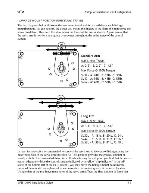
Autopilot Installation and Configuration LINKAGE MOUNT POSITION FORCE AND TRAVEL The two diagrams below illustrate the maximum travel and force available at each linkage mounting point. As can be seen, the closer you mount the linkage to the shaft, the more force the servo can deliver. However, this also means the travel of the arm is shorter. Again, ensure that the servo arm is nowhere near going over-center throughout the entire range of the control system. Standard Arm Max Linear Travel A: 2.6”, B: 2.2”, C: 1.8” Max Force @ 100% Torque SV32 - A: 24lb, B: 29lb, C: 36lb SV42 - A: 36lb, B: 44lb, C: 55lb SV52 - A: 48lb, B: 58lb, C: 72lb Long Arm Max Linear Travel A: 3.4”, B: 3.0”, C: 2.6” Max Force @ 100% Torque SV32L - A: 18lb, B: 20lb, C: 24lb SV42L - A: 27lb, B: 31lb, C: 36lb SV52L - A: 36lb, B: 41lb, C: 48lb In most instances, it is recommended to connect the servo arm to the control linkages using the outer-most hole of the servo arm (position A). This position provides the greatest amount of travel, with the least amount of drive force. If, when testing the autopilot, you find that the servos cannot adequately drive the control system (indicated by a yellow “slip indicator” in the AP status at the bottom left of the EFIS screen), you may move the linkage mount point inward, provided there is still enough travel to accommodate the control system at the servo location. Using either of the two inner-most holes of the servo arm affects the final amount of force that EFIS-D100 Installation Guide 6-9
- Page 1: EFIS-D100 Installation Guide This p
- Page 5 and 6: Table of Contents Contact Informati
- Page 7 and 8: 1. INTRODUCTION This manual provide
- Page 9 and 10: 2. WIRING OVERVIEW Please follow th
- Page 11 and 12: Wiring Overview The pin assignments
- Page 13 and 14: 3. INSTRUMENT INSTALLATION This sec
- Page 15 and 16: Instrument Installation The metal s
- Page 17 and 18: e accessed whenever you need to upd
- Page 19 and 20: Instrument Installation (range, MPG
- Page 21 and 22: Instrument Installation SERIAL ALTI
- Page 23 and 24: Instrument Installation Dynon Smart
- Page 25: Connecting Static & Pitot Lines The
- Page 28 and 29: EFIS Calibration and Configuration
- Page 30 and 31: EFIS Calibration and Configuration
- Page 32 and 33: DSAB Configuration Example Networks
- Page 34 and 35: DSAB Configuration Initial Setup As
- Page 36 and 37: DSAB Configuration Network Status T
- Page 38 and 39: Autopilot Installation and Configur
- Page 40 and 41: Autopilot Installation and Configur
- Page 42 and 43: Autopilot Installation and Configur
- Page 46 and 47: Autopilot Installation and Configur
- Page 48 and 49: Autopilot Installation and Configur
- Page 50 and 51: Autopilot Installation and Configur
- Page 52 and 53: Autopilot Installation and Configur
- Page 54 and 55: Autopilot Installation and Configur
- Page 56 and 57: Autopilot Installation and Configur
- Page 58 and 59: Autopilot Installation and Configur
- Page 60 and 61: Autopilot Installation and Configur
- Page 62 and 63: Autopilot Installation and Configur
- Page 64 and 65: Autopilot Installation and Configur
- Page 66 and 67: Autopilot Installation and Configur
- Page 69 and 70: 7. APPENDIX The appendices contain
- Page 71 and 72: Alert Message Description End condi
- Page 73 and 74: Appendix Problem After performing a
- Page 75 and 76: Appendix Appendix B: Dynon OAT Prob
- Page 77 and 78: Appendix CALIBRATION AND ADJUSTMENT
- Page 79 and 80: Pinouts and Function Description Ap
- Page 81 and 82: Generic Device Connections Appendix
- Page 83 and 84: Appendix EFIS-D100 Installation Gui
- Page 85 and 86: Appendix PANEL LOCATION AND MOUNTIN
- Page 87 and 88: Appendix HS34 CONFIGURATION This se
- Page 89 and 90: Appendix occur first in the NAV por
- Page 91 and 92: NAV and/or GPS Fail-over Appendix W
- Page 93 and 94: TOOLS AND MATERIALS REQUIRED Dynon
Autopilot <strong>Installation</strong> and Configuration<br />
LINKAGE MOUNT POSITION FORCE AND TRAVEL<br />
The two diagrams below illustrate the maximum travel and force available at each linkage<br />
mounting point. As can be seen, the closer you mount the linkage to the shaft, the more force the<br />
servo can deliver. However, this also means the travel of the arm is shorter. Again, ensure that<br />
the servo arm is nowhere near going over-center throughout the entire range of the control<br />
system.<br />
Standard Arm<br />
Max Linear Travel<br />
A: 2.6”, B: 2.2”, C: 1.8”<br />
Max Force @ 100% Torque<br />
SV32 - A: 24lb, B: 29lb, C: 36lb<br />
SV42 - A: 36lb, B: 44lb, C: 55lb<br />
SV52 - A: 48lb, B: 58lb, C: 72lb<br />
Long Arm<br />
Max Linear Travel<br />
A: 3.4”, B: 3.0”, C: 2.6”<br />
Max Force @ 100% Torque<br />
SV32L - A: 18lb, B: 20lb, C: 24lb<br />
SV42L - A: 27lb, B: 31lb, C: 36lb<br />
SV52L - A: 36lb, B: 41lb, C: 48lb<br />
In most instances, it is recommended to connect the servo arm to the control linkages using the<br />
outer-most hole of the servo arm (position A). This position provides the greatest amount of<br />
travel, with the least amount of drive force. If, when testing the autopilot, you find that the servos<br />
cannot adequately drive the control system (indicated by a yellow “slip indicator” in the AP<br />
status at the bottom left of the <strong>EFIS</strong> screen), you may move the linkage mount point inward,<br />
provided there is still enough travel to accommodate the control system at the servo location.<br />
Using either of the two inner-most holes of the servo arm affects the final amount of force that<br />
<strong>EFIS</strong>-<strong>D100</strong> <strong>Installation</strong> <strong>Guide</strong> 6-9


