User Manual - Lantech Communications Global Inc
User Manual - Lantech Communications Global Inc
User Manual - Lantech Communications Global Inc

You also want an ePaper? Increase the reach of your titles
YUMPU automatically turns print PDFs into web optimized ePapers that Google loves.
<strong>User</strong> <strong>Manual</strong><br />
7 10/100/1000T + 2 10/100/1000T/Mini-GBIC Combo<br />
Managed Switch<br />
Version 1.00<br />
December 2007<br />
i
Notice<br />
The contents of this manual are based on the table below listing firmware<br />
version, software kernel version, and hardware version. If the switch<br />
functions are different from the description of contents of manual, please<br />
contact the local sale dealer for more information.<br />
7 10/100/1000T + 2 10/100/1000T/Mini-GBIC Combo Managed<br />
Product name<br />
Switch<br />
Firmware Version V1.08<br />
Kernel Version V1.41<br />
ii
FCC Warning<br />
This Equipment has been tested and found to comply with the limits for a Class-A<br />
digital device, pursuant to Part 15 of the FCC rules. These limits are designed to<br />
provide reasonable protection against harmful interference in a residential installation.<br />
This equipment generates, uses, and can radiate radio frequency energy. It may<br />
cause harmful interference to radio communications if this equipment is not installed<br />
and used in accordance with the instructions. However, there is no guarantee that<br />
interference will not occur in a particular installation. If this equipment does cause<br />
harmful interference to radio or television reception, which can be determined by<br />
turning the equipment off and on, the user is encouraged to try to correct the<br />
interference by one or more of the following measures:<br />
• Reorient or relocate the receiving antenna.<br />
• <strong>Inc</strong>rease the separation between the equipment and receiver.<br />
• Connect the equipment into an outlet on a circuit different from that to which the<br />
receiver is connected.<br />
• Consult the dealer or an experienced radio/TV technician for help.<br />
CE Mark Warning<br />
This is a Class-A product. In a domestic environment this product may cause radio<br />
interference in which case the user may be required to take adequate measures.<br />
iii
Content<br />
Introduction ........................................................................................................................ 1<br />
Features ....................................................................................................................... 1<br />
7 10/100/1000T + 2 10/100/1000T/Mini-GBIC Combo Managed Switch ............... 1<br />
Software Feature .......................................................................................................... 3<br />
7 10/100/1000T + 2 10/100/1000T/Mini-GBIC Combo Managed Switch ............... 3<br />
Package Contents ........................................................................................................ 5<br />
Hardware Description ........................................................................................................ 6<br />
Physical Dimension ...................................................................................................... 6<br />
Front Panel ................................................................................................................... 6<br />
7 10/100/1000T + 2 10/100/1000T/Mini-GBIC Combo Managed Switch ............... 6<br />
Desktop Installation ...................................................................................................... 7<br />
Power On ...................................................................................................................... 8<br />
Network Application .......................................................................................................... 9<br />
Desktop Application ...................................................................................................... 9<br />
Segment Application ..................................................................................................... 9<br />
Console Management ...................................................................................................... 11<br />
Connecting to the Console Port .................................................................................. 11<br />
Login in the Console Interface .................................................................................... 11<br />
CLI Management ........................................................................................................ 13<br />
Commands Level ................................................................................................. 13<br />
Commands Set List ............................................................................................. 15<br />
Commands Set List ............................................................................................. 15<br />
System Commands Set ................................................................................ 15<br />
Port Commands Set ..................................................................................... 17<br />
Trunk Commands Set .................................................................................. 20<br />
VLAN Commands Set .................................................................................. 21<br />
Spanning Tree Commands Set .................................................................... 23<br />
QOS Commands Set .................................................................................... 26<br />
IGMP Commands Set .................................................................................. 26<br />
Mac / Filter Table Commands Set ................................................................ 27<br />
SNMP Commands Set ................................................................................. 28<br />
Port Mirroring Commands Set ...................................................................... 30<br />
iv
802.1x Commands Set ................................................................................. 31<br />
TFTP Commands Set ................................................................................... 33<br />
SystemLog, SMTP and Event Commands Set ............................................. 34<br />
SNTP Commands Set .................................................................................. 35<br />
X-ring Commands Set .................................................................................. 37<br />
Web-Based Management ................................................................................................ 38<br />
About Web-based Management ................................................................................. 38<br />
Preparing for Web Management ................................................................................. 38<br />
System Login .............................................................................................................. 39<br />
System Information ..................................................................................................... 40<br />
IP Configuration .......................................................................................................... 40<br />
DHCP Server – System configuration ......................................................................... 41<br />
DHCP Server – Client Entries ..................................................................................... 43<br />
DHCP Server - Port and IP Bindings .......................................................................... 43<br />
TFTP - Update Firmware ............................................................................................ 43<br />
TFTP – Restore Configuration .................................................................................... 44<br />
TFTP - Backup Configuration ..................................................................................... 45<br />
System Event Log – Syslog Configuration .................................................................. 45<br />
System Event Log - SMTP Configuration ................................................................... 46<br />
System Event Log - Event Configuration .................................................................... 48<br />
SNTP Configuration .................................................................................................... 49<br />
IP Security .................................................................................................................. 52<br />
<strong>User</strong> Authentication .................................................................................................... 53<br />
Port Statistics .............................................................................................................. 54<br />
Port Control ................................................................................................................ 55<br />
Port Trunk ................................................................................................................... 56<br />
Aggregator setting ............................................................................................... 56<br />
Aggregator Information ........................................................................................ 58<br />
State Activity ........................................................................................................ 59<br />
Port Mirroring .............................................................................................................. 60<br />
Rate Limiting ............................................................................................................... 61<br />
VLAN configuration ..................................................................................................... 63<br />
VLAN configuration - Port-based VLAN ............................................................... 63<br />
802.1Q VLAN ...................................................................................................... 67<br />
v
802.1Q Configuration ................................................................................... 67<br />
Group Configuration ..................................................................................... 69<br />
Rapid Spanning Tree .................................................................................................. 70<br />
RSTP - System Configuration.............................................................................. 70<br />
RSTP - Port Configuration ................................................................................... 72<br />
SNMP Configuration ................................................................................................... 73<br />
System Configuration .......................................................................................... 73<br />
Trap Configuration ............................................................................................... 75<br />
SNMPV3 Configuration ....................................................................................... 75<br />
Context Table ........................................................................................ 76<br />
<strong>User</strong> Profile ........................................................................................... 76<br />
Group Table .......................................................................................... 78<br />
Access Table ......................................................................................... 78<br />
MIBview Table ....................................................................................... 78<br />
QoS Configuration ...................................................................................................... 79<br />
QoS Policy and Priority Type ............................................................................... 79<br />
Port-based Priority ............................................................................................... 79<br />
COS Configuration .............................................................................................. 80<br />
TOS Configuration ............................................................................................... 80<br />
IGMP Configuration .................................................................................................... 81<br />
X-Ring ......................................................................................................................... 83<br />
Security ....................................................................................................................... 86<br />
802.1X/Radius Configuration ............................................................................... 86<br />
System Configuration ................................................................................... 86<br />
802.1x Per Port Configuration ...................................................................... 87<br />
Misc Configuration ........................................................................................ 88<br />
MAC Address Table ............................................................................................ 89<br />
Static MAC Address ..................................................................................... 89<br />
Add the Static MAC Address ........................................................................ 89<br />
MAC Filtering ................................................................................................ 90<br />
All MAC Addresses ...................................................................................... 91<br />
Factory Default ........................................................................................................... 92<br />
Save Configuration ..................................................................................................... 92<br />
System Reboot ........................................................................................................... 92<br />
vi
Troubleshooting .............................................................................................................. 94<br />
<strong>Inc</strong>orrect connections .................................................................................................. 94<br />
Faulty or loose cables ........................................................................... 94<br />
Non-standard cables ............................................................................. 94<br />
Improper Network Topologies ............................................................... 95<br />
Diagnosing LED Indicators ......................................................................................... 95<br />
Technical Specifications ................................................................................................. 96<br />
7 10/100/1000T + 2 10/100/1000T/Mini-GBIC Combo Managed Switch ............. 96<br />
vii
Introduction<br />
The switch is a multi-port switch that can be used to build high-performance switched<br />
workgroup networks. It provides wire-speed, Fast Ethernet switching function that allows<br />
high-performance, low-cost connection. The switch features a store-and-forward<br />
switching. Otherwise it can auto-learn and store source address on an 8K-entry MAC<br />
address table.<br />
Features<br />
* Future Release<br />
** Optional<br />
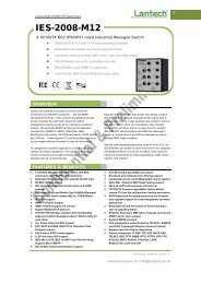
7 10/100/1000T + 2 10/100/1000T/Mini-GBIC Combo Managed Switch<br />
• System Interface/Performance<br />
‣ RJ-45 port support Auto MDI/MDI-X Function<br />
‣ Store-and-Forward Switching Architecture<br />
‣ Back-plane (Switching Fabric): 18Gbps<br />
‣ 1Mbits Packet Buffer<br />
‣ 8K MAC Address Table<br />
• VLAN<br />
‣ Port Based VLAN<br />
‣ Supports 802.1 Q Tag VLAN<br />
‣ GVRP<br />
‣ Double Tag VLAN (Q in Q)*<br />
‣ Private VLAN**<br />
• Port Trunk with LACP<br />
• QoS (Quality of Service)<br />
‣ Supports IEEE 802.1p Class of Service<br />
‣ Per port provides 4 priority queues<br />
‣ Port Base, Tag Base and Type of Service Priority<br />
• Port Mirror: Monitor traffic in switched networks<br />
1
‣ TX Packet only<br />
‣ RX Packet only<br />
‣ Both of TX and RX Packet<br />
• Security<br />
‣ Port Security: MAC address entries/filter<br />
‣ IP Security: IP address security management to prevent unauthorized intruder<br />
‣ Login Security: IEEE802.1X/RADIUS<br />
• IGMP with Query mode for Multi Media Application<br />
• Spanning Tree<br />
‣ Supports IEEE802.1d Spanning Tree<br />
‣ Supports IEEE802.1w Rapid Spanning Tree<br />
• X-ring<br />
‣ X-ring, Dual Homing, and Couple Ring Topology<br />
‣ Provides redundant backup feature and the recovery time below 300ms<br />
• Bandwidth Control<br />
‣ Ingress Packet Filter and Egress Rate Limit<br />
‣ Broadcast/Multicast Packet Filter Control<br />
• System Event Log<br />
‣ System Log Server/Client<br />
‣ SMTP e-mail Alert<br />
• SNMP Trap<br />
‣ Device cold start<br />
‣ Authentication failure<br />
‣ X-ring topology changed<br />
‣ Port Link up/Link down<br />
‣ Power Status<br />
• TFTP Firmware Upgrade and System Configuration Restore and Backup<br />
2
Software Feature<br />
* Future Release<br />
** Optional<br />
7 10/100/1000T + 2 10/100/1000T/Mini-GBIC Combo Managed Switch<br />
Management<br />
SNMP MIB<br />
VLAN<br />
SNMP v1, v2c, v3/Web/Telnet/CLI/Menu<br />
Driven**<br />
RFC 1215 Trap, RFC1213 MIBII, RFC 1157<br />
SNMP MIB, RFC 1493 Bridge MIB, RFC 2674<br />
VLAN MIB, RFC 1643 , RFC 1757, RSTP MIB,<br />
Private MIB<br />
Port Based VLAN<br />
IEEE 802.1Q Tag VLAN (256 entries)/ VLAN<br />
ID (Up to 4K, VLAN ID can be assigned from 1<br />
to 4096.)<br />
GVRP (256 Groups)<br />
Double Tag VLAN (Q in Q)*<br />
Private VLAN**<br />
Port Trunk with<br />
LACP<br />
LACP Port Trunk: 4 Trunk groups/Maximum 4<br />
trunk members<br />
Spanning Tree<br />
IEEE802.1d Spanning tree<br />
IEEE802.1w Rapid spanning tree<br />
X-ring<br />
Supports X-ring, Dual Homing, and Couple<br />
Ring<br />
Provides redundant backup feature and the<br />
recovery time below 300ms<br />
3
Quality of service<br />
Class of Service<br />
Port Security<br />
Port Mirror<br />
IGMP<br />
IP Security<br />
The quality of service determined by port, Tag<br />
and IPv4 Type of service, IPv4/ IPv6Different<br />
Service<br />
Supports IEEE802.1p class of service, per<br />
port provides 4 priority queues<br />
Supports 100 entries of MAC address for static<br />
MAC and another 100 for MAC filter<br />
Support 3 mirroring types: “RX, TX and Both<br />
packet”<br />
Supports IGMP snooping v1,v2<br />
256 multicast groups and IGMP query<br />
Supports 10 IP addresses that have<br />
permission to access the switch management<br />
and to prevent unauthorized intruder<br />
Login Security<br />
Supports IEEE802.1X Authentication/RADIUS<br />
Bandwidth Control<br />
Flow Control<br />
System Log<br />
Supports ingress packet filter and egress<br />
packet limit<br />
The egress rate control supports all of packet<br />
type and the limit rates are 100K ~ 250Mbps<br />
Ingress filter packet type combination rules are<br />
Broadcast/Multicast/Unknown Unicast packet,<br />
Broadcast/Multicast packet, Broadcast packet<br />
only and all of packet. The packet filter rate<br />
can be set from 100k to 250Mbps<br />
Supports Flow Control for Full-duplex and<br />
Back Pressure for Half-duplex<br />
Supports System log record and remote<br />
system log server<br />
4
SMTP<br />
SNMP Trap<br />
DHCP<br />
DNS<br />
SNTP<br />
TFTP<br />
Supports SMTP Server and 6 e-mail accounts<br />
for receiving event alert<br />
Up to 3 Trap stations<br />
Cold start, Port link up, Port link down,<br />
Authentication Failure, Private Trap for power<br />
status, X-ring topology change<br />
Provides DHCP Client/ DHCP Server/ IP<br />
Relay functions<br />
Provides DNS client feature and supports<br />
Primary and Secondary DNS server<br />
Supports SNTP to synchronize system clock<br />
in Internet<br />
Supports TFTP firmware update, TFTP<br />
configuration backup and restoration<br />
Package Contents<br />
Unpack the contents of the switch and verify them against the checklist below.<br />
• Switch x 1<br />
• Power Cord x 1<br />
• Rubber Pad x 4<br />
• RS-232 cable x 1<br />
• <strong>User</strong> <strong>Manual</strong> x 1<br />
Compare the contents of the switch package with the standard checklist above. If any<br />
item is missing or damaged, please contact your local dealer for service.<br />
5
Hardware Description<br />
This section mainly describes the hardware of the switch.<br />
Physical Dimension<br />
The physical dimensions of the switch are 217mm(W) x 140mm(D) x 43mm(H)<br />
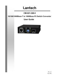
Front Panel<br />
7 10/100/1000T + 2 10/100/1000T/Mini-GBIC Combo Managed Switch<br />
The Front Panel of the switch consists of 7 x auto-sensing 10/100/1000Mbps Ethernet<br />
RJ-45 ports (automatic MDI/MDIX), 2 10/100/1000T/Mini-GBIC combo ports, and 1<br />
console port via RS-232 interface; and the LED indicators are also located on the front<br />
panel of the switch.<br />
Front Panel of the switch<br />
RJ-45 Ports (Auto MDI/MDIX)<br />
There are 7 10/100/1000 auto-sensing RJ-45 ports for 10Base-T, 100Base-TX, or<br />
1000Base-T connections. In general, MDI means connecting to another Hub or Switch<br />
while MDIX means connecting to a workstation or PC. Therefore, Auto MDI/MDIX means<br />
that you can connect to another Switch or workstation without changing non-crossover or<br />
crossover cabling.<br />
2 10/100/1000T/Mini-GBIC combo port<br />
Traditional RJ-45 ports can be used for uplinking wide-band paths in short distance<br />
6
(
Power On<br />
Connect the power cord to the power socket on the rear panel of the switch. The other<br />
side of power cord is connected to the power outlet. The internal power works with AC in<br />
the voltage range from 100-240V AC , frequency 50~60Hz (AC models) or 24 ~ 48 V DC<br />
(DC model). Check the power indicator on the front panel to see if power is properly<br />
supplied.<br />
8
Network Application<br />
This section provides you a few samples of network topology in which the switch is used.<br />
In general, the switch is designed to be used as a desktop or segment switch.<br />
Desktop Application<br />
The switch can be used as a standalone switch to which personal computers, server,<br />
printer server are directly connected to form small workgroup.<br />
Segment Application<br />
For enterprise networks where large data broadcast are constantly processed, this<br />
switch is suitable for department user to connect to the corporate backbone.<br />
You can use the switch to connect PCs, workstations, and servers to each other by<br />
connecting these devices directly to the upper level Switch. All the devices in this<br />
network can communicate with each other. Connecting servers to the backbone switch<br />
allows other users to access the server’s data.<br />
The switch automatically learns node address, which are subsequently used to filter and<br />
9
forward all traffic based on the destination address.<br />
10
Console Management<br />
Connecting to the Console Port<br />
Use the supplied RS-232 cable to connect a terminal or PC to the console port. The<br />
terminal or PC being connected must support the terminal emulation program.<br />
Connecting the switch to a terminal via RS-232 cable<br />
Login in the Console Interface<br />
When the connection between Switch and PC is ready, turn on the PC and run a terminal<br />
emulation program or Hyper Terminal and configure its communication parameters to<br />
match the following default characteristics of the console port:<br />
Baud Rate: 9600 bps<br />
Data Bits: 8<br />
Parity: none<br />
Stop Bit: 1<br />
Flow control: None<br />
11
The settings of communication parameters<br />
After finishing the parameter settings, click “OK“. When the blank screen shows up,<br />
press Enter key to bring out the login prompt. Key in the “root“ (default value) for the<br />
both <strong>User</strong> name and Password (use Enter key to switch), then press Enter key and the<br />
console management appears right after. Please see below figure for login screen.<br />
Console login interface<br />
12
CLI Management<br />
The system supports console management—CLI command. After you log in to the<br />
system, you will see a command prompt. To enter CLI management interface, enter<br />
“enable” command. The following table lists the CLI commands and description.<br />
CLI command interface<br />
Commands Level<br />
Modes<br />
Access<br />
Method<br />
Prompt<br />
Exit<br />
Method<br />
About This Mode<br />
The user commands<br />
available at the user<br />
<strong>User</strong> EXEC<br />
Begin a<br />
session with<br />
your switch.<br />
switch><br />
Enter<br />
logout or<br />
quit.<br />
level are a subset of<br />
those available at the<br />
privileged level.<br />
Use this mode to<br />
• Perform basic tests.<br />
• Display system<br />
13
information.<br />
The privileged<br />
Enter the<br />
command is the<br />
Privileged<br />
EXEC<br />
enable<br />
command<br />
while in <strong>User</strong><br />
switch#<br />
Enter<br />
disable to<br />
exit.<br />
advanced mode.<br />
Use this mode to<br />
• Display advanced<br />
EXEC mode.<br />
function status<br />
• Save configuration<br />
<strong>Global</strong><br />
Configuration<br />
Enter the<br />
configure<br />
command<br />
while in<br />
privileged<br />
EXEC mode.<br />
switch<br />
(config)#<br />
To exit to<br />
privileged<br />
EXEC<br />
mode, enter<br />
exit or end<br />
Use this mode to<br />
configure those<br />
parameters that are<br />
going to be applied to<br />
your switch.<br />
Enter the vlan<br />
database<br />
To exit to<br />
Use this mode to<br />
VLAN<br />
command<br />
switch<br />
user EXEC<br />
configure<br />
database<br />
while in<br />
(vlan)#<br />
mode, enter<br />
VLAN-specific<br />
privileged<br />
exit.<br />
parameters.<br />
EXEC mode.<br />
Enter the<br />
To exit to<br />
interface of<br />
global<br />
fast Ethernet<br />
configuratio<br />
command<br />
n mode,<br />
Use this mode to<br />
Interface<br />
(with a<br />
switch<br />
enter exit.<br />
configure parameters<br />
configuration<br />
specific<br />
(config-if)#<br />
To exit to<br />
for the switch and<br />
interface)<br />
privileged<br />
Ethernet ports.<br />
while in global<br />
EXEC<br />
configuration<br />
mode, enter<br />
mode<br />
exit or end.<br />
14
Commands Set List<br />
<strong>User</strong> EXEC<br />
Privileged EXEC<br />
<strong>Global</strong> configuration<br />
VLAN database<br />
Interface configuration<br />
Commands Set List<br />
System Commands Set<br />
E<br />
P<br />
G<br />
V<br />
I<br />
<strong>Lantech</strong> Commands Level Description Example<br />
show config E Show switch<br />
configuration<br />
show terminal P Show console<br />
information<br />
write memory P Save user<br />
configuration into<br />
permanent memory<br />
(flash rom)<br />
system name<br />
G Configure system<br />
[System Name]<br />
name<br />
system location<br />
G Set switch system<br />
[System Location]<br />
location string<br />
system description G Set switch system<br />
[System Description] description string<br />
system contact<br />
G Set switch system<br />
[System Contact]<br />
contact window string<br />
show system-info E Show system<br />
information<br />
ip address<br />
G Configure the IP<br />
[Ip-address]<br />
address of switch<br />
[Subnet-mask]<br />
[Gateway]<br />
switch>show config<br />
switch#show terminal<br />
switch#write memory<br />
switch(config)#system name xxx<br />
switch(config)#system location<br />
xxx<br />
switch(config)#system<br />
description xxx<br />
switch(config)#system contact<br />
xxx<br />
switch>show system-info<br />
switch(config)#ip address<br />
192.168.1.1 255.255.255.0<br />
192.168.1.254<br />
15
ip dhcp G Enable DHCP client<br />
function of switch<br />
switch(config)#ip dhcp<br />
show ip P Show IP information of switch#show ip<br />
switch<br />
no ip dhcp G Disable DHCP client<br />
function of switch<br />
switch(config)#no ip dhcp<br />
reload G Halt and perform a cold switch(config)#reload<br />
restart<br />
default G Restore to default switch(config)#default<br />
admin username<br />
[<strong>User</strong>name]<br />
admin password<br />
[Password]<br />
G<br />
G<br />
Changes a login<br />
username.<br />
(maximum 10 words)<br />
Specifies a password<br />
(maximum 10 words)<br />
show admin P Show administrator<br />
information<br />
switch(config)#admin username<br />
xxxxxx<br />
switch(config)#admin password<br />
xxxxxx<br />
switch#show admin<br />
dhcpserver enable G Enable DHCP Server switch(config)#dhcpserver enable<br />
dhcpserver disable G Disable DHCP Server switch(config)#no dhcpserver<br />
dhcpserver lowip<br />
[Low IP]<br />
dhcpserver highip<br />
[High IP]<br />
dhcpserver subnetmask<br />
[Subnet mask]<br />
dhcpserver gateway<br />
[Gateway]<br />
dhcpserver dnsip<br />
[DNS IP]<br />
dhcpserver leasetime<br />
[Hours]<br />
dhcpserver ipbinding<br />
[IP address]<br />
G<br />
G<br />
G<br />
G<br />
G<br />
G<br />
I<br />
Configure low IP<br />
address for IP pool<br />
Configure high IP<br />
address for IP pool<br />
Configure subnet<br />
switch(config)#dhcpserver lowip<br />
192.168.1.100<br />
switch(config)#dhcpserver highip<br />
192.168.1.200<br />
switch(config)#dhcpserver<br />
mask for DHCP clients subnetmask 255.255.255.0<br />
Configure gateway for<br />
DHCP clients<br />
Configure DNS IP for<br />
DHCP clients<br />
Configure lease time<br />
(in hour)<br />
Set static IP for DHCP<br />
clients by port<br />
switch(config)#dhcpserver<br />
gateway 192.168.1.254<br />
switch(config)#dhcpserver dnsip<br />
192.168.1.1<br />
switch(config)#dhcpserver<br />
leasetime 1<br />
switch(config)#interface<br />
fastEthernet 2<br />
switch(config)#dhcpserver<br />
ipbinding 192.168.1.1<br />
16
show dhcpserver<br />
configuration<br />
P Show configuration of<br />
DHCP server<br />
switch#show dhcpserver<br />
configuration<br />
show dhcpserver clients P Show client entries of switch#show dhcpserver clients<br />
DHCP server<br />
show dhcpserver<br />
ip-binding<br />
P Show IP-Binding<br />
information of DHCP<br />
switch#show dhcpserver<br />
ip-binding<br />
server<br />
no dhcpserver G Disable DHCP server switch(config)#no dhcpserver<br />
function<br />
security enable G Enable IP security switch(config)#security enable<br />
function<br />
security http G Enable IP security of switch(config)#security http<br />
HTTP server<br />
security telnet G Enable IP security of switch(config)#security telnet<br />
telnet server<br />
security ip<br />
[Index(1..10)] [IP<br />
G Set the IP security list switch(config)#security ip 1<br />
192.168.1.55<br />
Address]<br />
show security P Show the information switch#show security<br />
of IP security<br />
no security G Disable IP security switch(config)#no security<br />
function<br />
no security http G Disable IP security of switch(config)#no security http<br />
HTTP server<br />
no security telnet G Disable IP security of<br />
telnet server<br />
switch(config)#no security telnet<br />
Port Commands Set<br />
<strong>Lantech</strong> Commands Level Description Example<br />
interface fastEthernet<br />
[Portid]<br />
G Choose the port for<br />
modification.<br />
switch(config)#interface<br />
fastEthernet 2<br />
17
duplex<br />
[full | half]<br />
I Use the duplex<br />
configuration<br />
command to specify<br />
switch(config)#interface<br />
fastEthernet 2<br />
switch(config-if)#duplex full<br />
the duplex mode of<br />
operation for Fast<br />
Ethernet.<br />
speed<br />
[10|100|1000|auto]<br />
I Use the speed<br />
configuration<br />
command to specify<br />
switch(config)#interface<br />
fastEthernet 2<br />
switch(config-if)#speed 100<br />
the speed mode of<br />
operation for Fast<br />
Ethernet., the speed<br />
can’t be set to 1000 if<br />
the port isn’t a giga<br />
port..<br />
no flowcontrol I Disable flow control of switch(config-if)#no flowcontrol<br />
interface<br />
security enable I Enable security of<br />
interface<br />
switch(config)#interface<br />
fastEthernet 2<br />
switch(config-if)#security enable<br />
no security I Disable security of<br />
interface<br />
switch(config)#interface<br />
fastEthernet 2<br />
switch(config-if)#no security<br />
bandwidth type all I Set interface ingress<br />
limit frame type to<br />
“accept all frame”<br />
switch(config)#interface<br />
fastEthernet 2<br />
switch(config-if)#bandwidth type<br />
all<br />
bandwidth type<br />
broadcast-multicast-floo<br />
ded-unicast<br />
I Set interface ingress<br />
limit frame type to<br />
“accept broadcast,<br />
switch(config)#interface<br />
fastEthernet 2<br />
switch(config-if)#bandwidth type<br />
multicast, and flooded broadcast-multicast-flooded-uni<br />
unicast frame” cast<br />
bandwidth type I Set interface ingress switch(config)#interface<br />
18
oadcast-multicast<br />
limit frame type to fastEthernet 2<br />
“accept broadcast and switch(config-if)#bandwidth type<br />
multicast frame” broadcast-multicast<br />
bandwidth type<br />
broadcast-only<br />
I Set interface ingress<br />
limit frame type to<br />
switch(config)#interface<br />
fastEthernet 2<br />
“only accept broadcast switch(config-if)#bandwidth type<br />
frame”<br />
broadcast-only<br />
bandwidth in<br />
[Value]<br />
I Set interface input<br />
bandwidth. Rate<br />
Range is from 100<br />
switch(config)#interface<br />
fastEthernet 2<br />
switch(config-if)#bandwidth in 100<br />
kbps to 102400 kbps<br />
or to 256000 kbps for<br />
giga ports,<br />
and zero means no<br />
limit.<br />
bandwidth out<br />
[Value]<br />
Set interface output<br />
bandwidth. Rate<br />
Range is from 100<br />
kbps to 102400 kbps<br />
switch(config)#interface<br />
fastEthernet 2<br />
switch(config-if)#bandwidth out<br />
100<br />
or to 256000 kbps for<br />
giga ports,<br />
and zero means no<br />
limit.<br />
show bandwidth I Show interfaces<br />
bandwidth control<br />
switch(config)#interface<br />
fastEthernet 2<br />
switch(config-if)#show bandwidth<br />
state<br />
I Use the state interface switch(config)#interface<br />
[Enable | Disable]<br />
configuration fastEthernet 2<br />
command to specify switch(config-if)#state Disable<br />
the state mode of<br />
operation for Ethernet<br />
ports. Use the disable<br />
form of this command<br />
19
to disable the port.<br />
show interface<br />
configuration<br />
I show interface<br />
configuration status<br />
switch(config)#interface<br />
fastEthernet 2<br />
switch(config-if)#show interface<br />
configuration<br />
show interface status I show interface actual<br />
status<br />
switch(config)#interface<br />
fastEthernet 2<br />
switch(config-if)#show interface status<br />
show interface<br />
I show interface statistic switch(config)#interface<br />
accounting<br />
counter<br />
fastEthernet 2<br />
switch(config-if)#show interface<br />
accounting<br />
no accounting I Clear interface switch(config)#interface<br />
accounting information fastEthernet 2<br />
switch(config-if)#no accounting<br />
Trunk Commands Set<br />
<strong>Lantech</strong> Commands Level Description Example<br />
aggregator priority G Set port group system switch(config)#aggregator priority<br />
[1~65535]<br />
priority<br />
22<br />
aggregator activityport<br />
[Group ID]<br />
G Set activity port switch(config)#aggregator<br />
activityport 2<br />
[Port Numbers]<br />
aggregator group<br />
[GroupID] [Port-list]<br />
lacp<br />
G Assign a trunk group<br />
with LACP active.<br />
[GroupID] :1~3<br />
switch(config)#aggregator group<br />
1 1-4 lacp workp 2<br />
or<br />
workp<br />
[Port-list]:Member port switch(config)#aggregator group<br />
[Workport]<br />
list, This parameter<br />
could be a port<br />
range(ex.1-4) or a port<br />
list separate by a<br />
comma(ex.2, 3, 6)<br />
2 1,4,3 lacp workp 3<br />
20
[Workport]: The<br />
amount of work ports,<br />
this value could not be<br />
less than zero or be<br />
large than the amount<br />
of member ports.<br />
aggregator group<br />
[GroupID] [Port-list]<br />
nolacp<br />
G Assign a static trunk<br />
group.<br />
[GroupID] :1~3<br />
[Port-list]:Member port<br />
list, This parameter<br />
could be a port<br />
range(ex.1-4) or a port<br />
list separate by a<br />
comma(ex.2, 3, 6)<br />
show aggregator P Show the information<br />
of trunk group<br />
no aggregator lacp G Disable the LACP<br />
[GroupID]<br />
function of trunk group<br />
switch(config)#aggregator group<br />
1 2-4 nolacp<br />
or<br />
switch(config)#aggregator group<br />
1 3,1,2 nolacp<br />
switch#show aggregator 1<br />
or<br />
switch#show aggregator 2<br />
or<br />
switch#show aggregator 3<br />
switch(config)#no aggreator lacp<br />
1<br />
no aggregator group<br />
[GroupID]<br />
G<br />
Remove a trunk group switch(config)#no aggreator<br />
group 2<br />
VLAN Commands Set<br />
<strong>Lantech</strong> Commands Level Description Example<br />
vlan database P Enter VLAN configure switch#vlan database<br />
mode<br />
Vlanmode<br />
V To set switch VLAN switch(vlan)#vlanmode portbase<br />
[portbase| 802.1q |<br />
mode.<br />
or<br />
gvrp]<br />
switch(vlan)#vlanmode 802.1q<br />
or<br />
21
switch(vlan)#vlanmode gvrp<br />
no vlan V No VLAN Switch(vlan)#no vlan<br />
Ported based VLAN configuration<br />
vlan port-based<br />
grpname<br />
[Group Name]<br />
grpid<br />
[GroupID]<br />
port<br />
[PortNumbers]<br />
show vlan [GroupID]<br />
or<br />
show vlan<br />
no vlan group<br />
[GroupID]<br />
vlan 8021q name<br />
[GroupName]<br />
vid<br />
[VID]<br />
vlan 8021q port<br />
[PortNumber]<br />
access-link untag<br />
[UntaggedVID]<br />
vlan 8021q port<br />
[PortNumber]<br />
trunk-link tag<br />
[TaggedVID List]<br />
vlan 8021q port<br />
[PortNumber]<br />
hybrid-link untag<br />
V<br />
V<br />
V<br />
V<br />
V<br />
V<br />
V<br />
Add new port based<br />
VALN<br />
Show VLAN<br />
information<br />
switch(vlan)#vlan port-based<br />
grpname test grpid 2 port 2-4<br />
or<br />
switch(vlan)#vlan port-based<br />
grpname test grpid 2 port 2,3,4<br />
switch(vlan)#show vlan 23<br />
Delete port base group switch(vlan)#no vlan group 2<br />
ID<br />
IEEE 802.1Q VLAN<br />
Change the name of<br />
VLAN group, if the<br />
group didn’t exist, this<br />
command can’t be<br />
applied.<br />
Assign a access link<br />
switch(vlan)#vlan 8021q name<br />
test vid 22<br />
for VLAN by port, if the access-link untag 33<br />
port belong to a trunk<br />
group, this command<br />
can’t be applied.<br />
Assign a trunk link for<br />
VLAN by port, if the<br />
port belong to a trunk<br />
group, this command<br />
can’t be applied.<br />
switch(vlan)#vlan 8021q port 3<br />
switch(vlan)#vlan 8021q port 3<br />
trunk-link tag 2,3,6,99<br />
or<br />
switch(vlan)#vlan 8021q port 3<br />
trunk-link tag 3-20<br />
Assign a hybrid link for switch(vlan)#vlan 8021q port 3<br />
VLAN by port, if the<br />
port belong to a trunk<br />
hybrid-link untag 4 tag 3,6,8<br />
or<br />
22
[UntaggedVID]<br />
tag<br />
[TaggedVID List]<br />
vlan 8021q trunk<br />
[PortNumber]<br />
access-link untag<br />
[UntaggedVID]<br />
vlan 8021q trunk<br />
[PortNumber]<br />
trunk-link tag<br />
[TaggedVID List]<br />
vlan 8021q trunk<br />
[PortNumber]<br />
hybrid-link untag<br />
[UntaggedVID]<br />
tag<br />
[TaggedVID List]<br />
show vlan [GroupID]<br />
or<br />
show vlan<br />
no vlan group<br />
[GroupID]<br />
V<br />
V<br />
V<br />
V<br />
V<br />
group, this command switch(vlan)#vlan 8021q port 3<br />
can’t be applied. hybrid-link untag 5 tag 6-8<br />
Assign a access link switch(vlan)#vlan 8021q trunk 3<br />
for VLAN by trunk access-link untag 33<br />
group<br />
Assign a trunk link for switch(vlan)#vlan 8021q trunk 3<br />
VLAN by trunk group trunk-link tag 2,3,6,99<br />
or<br />
switch(vlan)#vlan 8021q trunk 3<br />
trunk-link tag 3-20<br />
Assign a hybrid link for switch(vlan)#vlan 8021q trunk 3<br />
VLAN by trunk group hybrid-link untag 4 tag 3,6,8<br />
or<br />
switch(vlan)#vlan 8021q trunk 3<br />
hybrid-link untag 5 tag 6-8<br />
Show VLAN<br />
switch(vlan)#show vlan 23<br />
information<br />
Delete port base group switch(vlan)#no vlan group 2<br />
ID<br />
Spanning Tree Commands Set<br />
<strong>Lantech</strong> Commands Level Description Example<br />
spanning-tree enable G Enable spanning tree switch(config)#spanning-tree<br />
enable<br />
spanning-tree priority G Configure spanning switch(config)#spanning-tree<br />
[0~61440]<br />
tree priority parameter priority 32767<br />
spanning-tree max-age<br />
[seconds]<br />
G Use the spanning-tree<br />
max-age global<br />
configuration<br />
command to change<br />
switch(config)#spanning-tree<br />
max-age 15<br />
23
spanning-tree<br />
hello-time [seconds]<br />
spanning-tree<br />
forward-time [seconds]<br />
G<br />
G<br />
the interval between<br />
messages the<br />
spanning tree receives<br />
from the root switch. If<br />
a switch does not<br />
receive a bridge<br />
protocol data unit<br />
(BPDU) message from<br />
the root switch within<br />
this interval, it<br />
recomputed the<br />
Spanning Tree<br />
Protocol (STP)<br />
topology.<br />
Use the spanning-tree switch(config)#spanning-tree<br />
hello-time global hello-time 3<br />
configuration<br />
command to specify<br />
the interval between<br />
hello bridge protocol<br />
data units (BPDUs).<br />
Use the spanning-tree switch(config)#spanning-tree<br />
forward-time global forward-time 20<br />
configuration<br />
command to set the<br />
forwarding-time for the<br />
specified<br />
spanning-tree<br />
instances. The<br />
forwarding time<br />
determines how long<br />
each of the listening<br />
and<br />
learning states last<br />
24
stp-path-cost<br />
[1~200000000]<br />
stp-path-priority<br />
[Port Priority]<br />
stp-admin-p2p<br />
[Auto|True|False]<br />
stp-admin-edge<br />
[True|False]<br />
I<br />
I<br />
I<br />
I<br />
before the port begins<br />
forwarding.<br />
Use the spanning-tree switch(config)#interface<br />
cost interface fastEthernet 2<br />
configuration switch(config-if)#stp-path-cost 20<br />
command to set the<br />
path cost for Spanning<br />
Tree<br />
Protocol (STP)<br />
calculations. In the<br />
event of a loop,<br />
spanning tree<br />
considers the path<br />
cost when selecting<br />
an interface to place<br />
into the forwarding<br />
state.<br />
Use the spanning-tree switch(config)#interface<br />
port-priority interface fastEthernet 2<br />
configuration switch(config-if)#stp-path-priority<br />
command to configure 128<br />
a port priority that<br />
is used when two<br />
switches tie for<br />
position as the root<br />
switch.<br />
Admin P2P of STP switch(config)#interface<br />
priority on this fastEthernet 2<br />
interface.<br />
switch(config-if)#stp-admin-p2p<br />
Auto<br />
Admin Edge of STP switch(config)#interface<br />
priority on this fastEthernet 2<br />
interface.<br />
switch(config-if)#stp-admin-edge<br />
True<br />
25
stp-admin-non-stp I Admin NonSTP of STP switch(config)#interface<br />
[True|False]<br />
priority on this<br />
interface.<br />
fastEthernet 2<br />
switch(config-if)#stp-admin-non-s<br />
tp False<br />
show spanning-tree E Displays a summary of switch>show spanning-tree<br />
the spanning-tree<br />
states.<br />
no spanning-tree G Disable spanning-tree. switch(config)#no spanning-tree<br />
QOS Commands Set<br />
<strong>Lantech</strong> Commands Level Description Example<br />
qos policy<br />
[weighted-fair|strict]<br />
qos prioritytype<br />
[port-based|cos-only|tos<br />
-only|cos-first|tos-first]<br />
qos priority portbased<br />
[Port]<br />
[lowest|low|middle|high]<br />
qos priority cos<br />
[Priority][lowest|low|mid<br />
dle|high]<br />
qos priority tos<br />
[Priority][lowest|low|mid<br />
dle|high]<br />
G<br />
G<br />
G<br />
Select QOS policy<br />
scheduling<br />
Setting of QOS priority<br />
type<br />
Configure Port-based<br />
Priority<br />
show qos P Displays the<br />
switch(config)#qos policy<br />
weighted-fair<br />
switch(config)#qos prioritytype<br />
switch(config)#qos priority<br />
portbased 1 low<br />
G Configure COS Priority switch(config)#qos priority cos 0<br />
middle<br />
G Configure TOS Priority switch(config)#qos priority tos 3<br />
high<br />
information of QoS<br />
configuration<br />
Switch#show qos<br />
no qos G Disable QoS function switch(config)#no qos<br />
IGMP Commands Set<br />
<strong>Lantech</strong> Commands Level Description Example<br />
igmp enable G Enable IGMP<br />
snooping function<br />
switch(config)#igmp enable<br />
26
Igmp-query auto G Set IGMP query to switch(config)#Igmp-query auto<br />
auto mode<br />
Igmp-query force G Set IGMP query to switch(config)#Igmp-query force<br />
force mode<br />
show igmp<br />
P Displays the details of switch#show igmp configuration<br />
configuration<br />
an IGMP<br />
configuration.<br />
show igmp multi P Displays the details of switch#show igmp multi<br />
an IGMP snooping<br />
entries.<br />
no igmp G Disable IGMP switch(config)#no igmp<br />
snooping function<br />
no igmp-query G Disable IGMP query switch#no igmp-query<br />
Mac / Filter Table Commands Set<br />
<strong>Lantech</strong> Commands Level Description Example<br />
mac-address-table static<br />
hwaddr<br />
[MAC]<br />
I Configure MAC<br />
address table of<br />
interface (static).<br />
switch(config)#interface<br />
fastEthernet 2<br />
switch(config-if)#mac-address-tab<br />
le static hwaddr 000012345678<br />
mac-address-table filter<br />
hwaddr<br />
G Configure MAC<br />
address table(filter)<br />
switch(config)#mac-address-table<br />
filter hwaddr 000012348678<br />
[MAC]<br />
show mac-address-table P Show all MAC address switch#show mac-address-table<br />
table<br />
show mac-address-table<br />
static<br />
P Show static MAC<br />
address table<br />
switch#show mac-address-table<br />
static<br />
show mac-address-table P Show filter MAC<br />
filter<br />
address table.<br />
no mac-address-table I Remove an entry of<br />
static hwaddr<br />
MAC address table of<br />
[MAC]<br />
interface (static)<br />
27<br />
switch#show mac-address-table<br />
filter<br />
switch(config)#interface<br />
fastEthernet 2<br />
switch(config-if)#no<br />
mac-address-table static hwaddr
000012345678<br />
no mac-address-table<br />
filter hwaddr<br />
[MAC]<br />
G Remove an entry of<br />
MAC address table<br />
(filter)<br />
switch(config)#no<br />
mac-address-table filter hwaddr<br />
000012348678<br />
no mac-address-table G Remove dynamic entry switch(config)#no<br />
of MAC address table mac-address-table<br />
SNMP Commands Set<br />
<strong>Lantech</strong> Commands Level Description Example<br />
snmp system-name G Set SNMP agent switch(config)#snmp<br />
[System Name]<br />
system name system-name l2switch<br />
snmp system-location G Set SNMP agent switch(config)#snmp<br />
[System Location]<br />
system location system-location lab<br />
snmp system-contact G Set SNMP agent switch(config)#snmp<br />
[System Contact]<br />
system contact system-contact where<br />
snmp agent-mode G Select the agent mode switch(config)#snmp agent-mode<br />
[v1v2c|v3|v1v2cv3]<br />
of SNMP<br />
v1v2cv3<br />
snmp<br />
G Add SNMP community switch(config)#snmp<br />
community-strings<br />
string.<br />
community-strings public right<br />
[Community]<br />
rw<br />
right<br />
[RO/RW]<br />
snmp-server host G Configure SNMP switch(config)#snmp-server host<br />
[IP address]<br />
server host information 192.168.1.50 community public<br />
community<br />
and community string trap-version v1<br />
[Community-string]<br />
(remove)<br />
trap-version<br />
Switch(config)#<br />
[v1|v2c]<br />
no snmp-server host<br />
192.168.1.50<br />
snmpv3 context-name G Configure the context switch(config)#snmpv3<br />
[Context Name ]<br />
name<br />
context-name Test<br />
snmpv3 user<br />
G Configure the switch(config)#snmpv3 user<br />
[<strong>User</strong> Name]<br />
userprofile for test01 group G1 password<br />
28
group<br />
[Group Name]<br />
password<br />
SNMPV3 agent.<br />
Privacy password<br />
could be empty.<br />
[Authentication<br />
Password] [Privacy<br />
Password]<br />
snmpv3 access<br />
G Configure the access<br />
context-name [Context table of SNMPV3<br />
Name ]<br />
agent<br />
group<br />
[Group Name ]<br />
security-level<br />
[NoAuthNoPriv|AuthNoP<br />
riv|AuthPriv]<br />
match-rule<br />
[Exact|Prifix]<br />
views<br />
[Read View Name] [Write<br />
View Name] [Notify View<br />
Name]<br />
snmpv3 mibview view G<br />
[View Name]<br />
type<br />
[Excluded|<strong>Inc</strong>luded]<br />
sub-oid<br />
[OID]<br />
Configure the mibview<br />
table of SNMPV3<br />
agent<br />
show snmp P Show SNMP<br />
configuration<br />
no snmp<br />
G Remove the specified<br />
community-strings<br />
community.<br />
[Community]<br />
no snmp-server host G Remove the SNMP<br />
[Host-address]<br />
server host.<br />
AuthPW PrivPW<br />
switch(config)#snmpv3 access<br />
context-name Test group G1<br />
security-level AuthPriv<br />
match-rule Exact views V1 V1 V1<br />
switch(config)#snmpv3 mibview<br />
view V1 type Excluded sub-oid<br />
1.3.6.1<br />
switch#show snmp<br />
switch(config)#no snmp<br />
community-strings public<br />
switch(config)#no snmp-server<br />
192.168.1.50<br />
29
no snmpv3 user<br />
[<strong>User</strong> Name]<br />
no snmpv3 access<br />
context-name [Context<br />
Name ]<br />
group<br />
[Group Name ]<br />
security-level<br />
[NoAuthNoPriv|AuthNoP<br />
riv|AuthPriv]<br />
match-rule<br />
[Exact|Prifix]<br />
views<br />
[Read View Name] [Write<br />
View Name] [Notify View<br />
Name]<br />
no snmpv3 mibview<br />
view<br />
[View Name]<br />
type<br />
[Excluded|<strong>Inc</strong>luded]<br />
sub-oid<br />
[OID]<br />
G<br />
G<br />
G<br />
Remove specified user switch(config)#no snmpv3 user<br />
of SNMPv3 agent. Test<br />
Remove specified switch(config)#no snmpv3 access<br />
access table of context-name Test group G1<br />
SNMPv3 agent. security-level AuthPr<br />
iv match-rule Exact views V1 V1<br />
V1<br />
Remove specified switch(config)#no snmpv3<br />
mibview table of mibview view V1 type Excluded<br />
SNMPV3 agent. sub-oid 1.3.6.1<br />
Port Mirroring Commands Set<br />
<strong>Lantech</strong> Commands Level Description Example<br />
monitor rx G Set RX destination switch(config)#monitor rx<br />
port of monitor function<br />
monitor tx G Set TX destination port switch(config)#monitor tx<br />
of monitor function<br />
show monitor P Show port monitor switch#show monitor<br />
information<br />
monitor I Configure source port switch(config)#interface<br />
30
[RX|TX|Both] of monitor function fastEthernet 2<br />
switch(config-if)#monitor RX<br />
show monitor I Show port monitor<br />
information<br />
switch(config)#interface<br />
fastEthernet 2<br />
switch(config-if)#show monitor<br />
no monitor I Disable source port of switch(config)#interface<br />
monitor function fastEthernet 2<br />
switch(config-if)#no monitor<br />
802.1x Commands Set<br />
<strong>Lantech</strong> Commands Level Description Example<br />
8021x enable G Use the 802.1x global switch(config)# 8021x enable<br />
configuration<br />
command to enable<br />
802.1x protocols.<br />
8021x system radiusip G Use the 802.1x system switch(config)# 8021x system<br />
[IP address]<br />
radius IP global radiusip 192.168.1.1<br />
configuration<br />
command to change<br />
the radius server IP.<br />
8021x system serverport G Use the 802.1x system switch(config)# 8021x system<br />
[port ID]<br />
server port global serverport 1815<br />
configuration<br />
command to change<br />
the radius server port<br />
8021x system<br />
G Use the 802.1x system switch(config)# 8021x system<br />
accountport<br />
account port global accountport 1816<br />
[port ID]<br />
configuration<br />
command to change<br />
the accounting port<br />
8021x system sharekey G Use the 802.1x system switch(config)# 8021x system<br />
[ID]<br />
share key global<br />
configuration<br />
sharekey 123456<br />
31
8021x system nasid<br />
[words]<br />
8021x misc quietperiod<br />
[sec.]<br />
8021x misc txperiod<br />
[sec.]<br />
8021x misc<br />
supportimeout [sec.]<br />
8021x misc<br />
servertimeout [sec.]<br />
8021x misc maxrequest<br />
[number]<br />
G<br />
G<br />
G<br />
G<br />
G<br />
G<br />
command to change<br />
the shared key value.<br />
Use the 802.1x system switch(config)# 8021x system<br />
nasid global<br />
nasid test1<br />
configuration<br />
command to change<br />
the NAS ID<br />
Use the 802.1x misc switch(config)# 8021x misc<br />
quiet period global quietperiod 10<br />
configuration<br />
command to specify<br />
the quiet period value<br />
of the switch.<br />
Use the 802.1x misc switch(config)# 8021x misc<br />
TX period global txperiod 5<br />
configuration<br />
command to set the<br />
TX period.<br />
Use the 802.1x misc switch(config)# 8021x misc<br />
supp timeout global supportimeout 20<br />
configuration<br />
command to set the<br />
supplicant timeout.<br />
Use the 802.1x misc switch(config)#8021x misc<br />
server timeout global servertimeout 20<br />
configuration<br />
command to set the<br />
server timeout.<br />
Use the 802.1x misc switch(config)# 8021x misc<br />
max request global maxrequest 3<br />
configuration<br />
command to set the<br />
MAX requests.<br />
32
8021x misc<br />
reauthperiod [sec.]<br />
G Use the 802.1x misc<br />
reauth period global<br />
switch(config)# 8021x misc<br />
reauthperiod 3000<br />
configuration<br />
command to set the<br />
reauth period.<br />
8021x portstate<br />
[disable | reject | accept |<br />
authorize]<br />
I Use the 802.1x port<br />
state interface<br />
configuration<br />
command to set the<br />
switch(config)#interface<br />
fastethernet 3<br />
switch(config-if)#8021x portstate<br />
accept<br />
state of the selected<br />
port.<br />
show 8021x E Displays a summary of switch>show 8021x<br />
the 802.1x properties<br />
and also the port<br />
sates.<br />
no 8021x G Disable 802.1x<br />
function<br />
switch(config)#no 8021x<br />
TFTP Commands Set<br />
<strong>Lantech</strong> Commands Level Description Defaults Example<br />
backup<br />
flash:backup_cfg<br />
G Save configuration to<br />
TFTP and need to<br />
switch(config)#backup<br />
flash:backup_cfg<br />
specify the IP of TFTP<br />
server and the file name<br />
of image.<br />
restore flash:restore_cfg G Get configuration from switch(config)#restore<br />
TFTP server and need to flash:restore_cfg<br />
specify the IP of TFTP<br />
server and the file name<br />
of image.<br />
upgrade<br />
flash:upgrade_fw<br />
G Upgrade firmware by<br />
TFTP and need to<br />
specify the IP of TFTP<br />
switch(config)#upgrade<br />
lash:upgrade_fw<br />
33
server and the file name<br />
of image.<br />
SystemLog, SMTP and Event Commands Set<br />
<strong>Lantech</strong> Commands Level Description Example<br />
systemlog ip<br />
G Set System log server switch(config)# systemlog ip<br />
[IP address]<br />
IP address.<br />
192.168.1.100<br />
systemlog mode<br />
[client|server|both]<br />
G Specified the log mode switch(config)# systemlog mode<br />
both<br />
show systemlog E Displays system log. Switch>show systemlog<br />
show systemlog P Show system log client switch#show systemlog<br />
& server information<br />
no systemlog G Disable systemlog switch(config)#no systemlog<br />
functon<br />
smtp enable G Enable SMTP function switch(config)#smtp enable<br />
smtp serverip<br />
[IP address]<br />
G Configure SMTP<br />
server IP<br />
switch(config)#smtp serverip<br />
192.168.1.5<br />
smtp authentication G Enable SMTP<br />
authentication<br />
switch(config)#smtp<br />
authentication<br />
smtp account<br />
G Configure<br />
switch(config)#smtp account<br />
[account]<br />
authentication account John<br />
smtp password<br />
[password]<br />
G Configure<br />
authentication<br />
switch(config)#smtp password<br />
1234<br />
password<br />
smtp rcptemail<br />
G Configure Rcpt e-mail switch(config)#smtp rcptemail 1<br />
[Index] [Email address] Address<br />
Alert@test.com<br />
show smtp P Show the information switch#show smtp<br />
of SMTP<br />
no smtp G Disable SMTP function switch(config)#no smtp<br />
event device-cold-start<br />
[Systemlog|SMTP|Both]<br />
G Set cold start event<br />
type<br />
switch(config)#event<br />
device-cold-start both<br />
event<br />
authentication-failure<br />
G Set Authentication<br />
failure event type<br />
switch(config)#event<br />
authentication-failure both<br />
34
[Systemlog|SMTP|Both]<br />
event<br />
ring-topology-change<br />
G Set X-ring topology<br />
changed event type<br />
switch(config)#event<br />
ring-topology-change both<br />
[Systemlog|SMTP|Both]<br />
event systemlog<br />
[Link-UP|Link-Down|Bot<br />
h]<br />
I Set port event for<br />
system log<br />
switch(config)#interface<br />
fastethernet 3<br />
switch(config-if)#event systemlog<br />
both<br />
event smtp<br />
[Link-UP|Link-Down|Bot<br />
h]<br />
I Set port event for<br />
SMTP<br />
switch(config)#interface<br />
fastethernet 3<br />
switch(config-if)#event smtp both<br />
show event P Show event selection switch#show event<br />
no event<br />
device-cold-start<br />
G Disable cold start<br />
event type<br />
switch(config)#no event<br />
device-cold-start<br />
no event<br />
G Disable Authentication switch(config)#no event<br />
authentication-failure failure event typ authentication-failure<br />
no event<br />
X-ring-topology-change<br />
G Disable X-ring<br />
topology changed<br />
switch(config)#no event<br />
X-ring-topology-change<br />
event type<br />
no event systemlog I Disable port event for<br />
system log<br />
switch(config)#interface<br />
fastethernet 3<br />
switch(config-if)#no event<br />
systemlog<br />
no event smpt I Disable port event for<br />
SMTP<br />
switch(config)#interface<br />
fastethernet 3<br />
switch(config-if)#no event smtp<br />
show systemlog P Show system log client switch#show systemlog<br />
& server information<br />
SNTP Commands Set<br />
<strong>Lantech</strong> Commands Level Description Example<br />
sntp enable G Enable SNTP function switch(config)#sntp enable<br />
35
sntp daylight G Enable daylight saving switch(config)#sntp daylight<br />
time, if SNTP function<br />
is inactive, this<br />
command can’t be<br />
applied.<br />
sntp daylight-period<br />
[Start time] [End time]<br />
G Set period of daylight<br />
saving time, if SNTP<br />
function is inactive,<br />
switch(config)# sntp<br />
daylight-period 20060101-01:01<br />
20060202-01:01<br />
this command can’t be<br />
applied.<br />
Parameter format:<br />
[yyyymmdd-hh:mm]<br />
sntp daylight-offset<br />
[Minute]<br />
G Set offset of daylight<br />
saving time, if SNTP<br />
switch(config)#sntp<br />
daylight-offset 3<br />
function is inactive,<br />
this command can’t be<br />
applied.<br />
sntp ip<br />
G Set SNTP server IP, if switch(config)#sntp ip 192.169.1.1<br />
[IP]<br />
SNTP function is<br />
inactive, this command<br />
can’t be applied.<br />
sntp timezone<br />
G Set timezone index, switch(config)#sntp timezone 22<br />
[Timezone]<br />
use “show sntp<br />
timzezone” command<br />
to get more<br />
information of index<br />
number<br />
show sntp P Show SNTP switch#show sntp<br />
information<br />
show sntp timezone P Show index number of switch#show sntp timezone<br />
time zone list<br />
no sntp G Disable SNTP function switch(config)#no sntp<br />
no sntp daylight G Disable daylight saving switch(config)#no sntp daylight<br />
36
time<br />
X-ring Commands Set<br />
<strong>Lantech</strong> Commands Level Description Example<br />
Xring enable G Enable X-ring switch(config)#Xring enable<br />
Xring master G Enable ring master switch(config)#Xring master<br />
Xring couplering G Enable couple ring switch(config)#Xring couplering<br />
Xring dualhoming G Enable dual homing switch(config)#Xring dualhoming<br />
Xring ringport<br />
G Configure 1st/2nd switch(config)#Xring ringport 7 8<br />
[1st Ring Port] [2nd Ring<br />
Port]<br />
Ring Port<br />
Xring couplingport<br />
[Coupling Port]<br />
G Configure Coupling<br />
Port<br />
switch(config)#Xring couplingport<br />
1<br />
Xring controlport G Configure Control Port switch(config)#Xring controlport 2<br />
[Control Port]<br />
Xring homingport<br />
[Dual Homing Port]<br />
G Configure Dual<br />
Homing Port<br />
switch(config)#Xring homingport<br />
3<br />
show Xring P Show the information switch#show Xring<br />
of X - Ring<br />
no Xring G Disable X-ring switch(config)#no Xring<br />
no Xring master G Disable ring master switch(config)# no Xring master<br />
no Xring couplering G Disable couple ring switch(config)# no Xring<br />
couplering<br />
no Xring dualhoming G Disable dual homing switch(config)# no Xring<br />
dualhoming<br />
37
Web-Based Management<br />
This section introduces the configuration and functions of the Web-Based management.<br />
About Web-based Management<br />
Inside the CPU board of the switch exists an embedded HTML web site residing in flash<br />
memory. It offers advanced management features and allow users to manage the switch<br />
from anywhere on the network through a standard browser such as Microsoft Internet<br />
Explorer.<br />
The Web-Based Management supports Internet Explorer 6.0. It is based on Java Applets<br />
with an aim to reduce network bandwidth consumption, enhance access speed and<br />
present an easy viewing screen.<br />
Preparing for Web Management<br />
Before using web management, you can use console to log in the switch checking the<br />
default IP of the Switch. Please refer to Console Management Chapter for console login.<br />
If you need change IP address in first time, you can use console mode to modify it. The<br />
default value is as below:<br />
IP Address: 192.168.16.1<br />
Subnet Mask: 255.255.255.0<br />
Default Gateway: 192.168.16.254<br />
<strong>User</strong> Name: root Password: root<br />
38
System Login<br />
1. Launch the Internet Explorer on the PC<br />
2. Key in “http:// “+” the IP address of the switch”, and then Press “Enter”.<br />
Uniform Resource Locator<br />
3. The login screen appears right after.<br />
4. Key in the user name and password. The default user name and password are the<br />
same as ‘root’<br />
5. Press Enter or click OK button, and then the home screen of the Web-based<br />
management shows up.<br />
Login screen<br />
Note: The web interface features shown below are introduced by the screen<br />
displays of 7 10/100/1000T + 2 10/100/1000T/Mini-GBIC Combo Managed Switch.<br />
Unless specifically identified, all of the screen displays are suitable for the<br />
switches involved in this manual.<br />
39
System Information<br />
Assign the system name and location and view the system information.<br />
• System Name: Assign the system name of the switch (The maximum length is 64<br />
bytes)<br />
• System Description: Describes the switch.<br />
• System Location: Assign the switch physical location (The maximum length is 64<br />
bytes).<br />
• System Contact: Enter the name of contact person or organization.<br />
• Firmware Version: Displays the switch’s firmware version<br />
• Kernel Version: Displays the kernel software version<br />
• MAC Address: Displays the unique hardware address assigned by manufacturer<br />
(default)<br />
• And than, click Apply button.<br />
System information interface<br />
IP Configuration<br />
<strong>User</strong> can configure the IP Settings and DHCP client function in here.<br />
• DHCP Client: Enable or disable the DHCP client function. When DHCP client<br />
function is enabled, the industrial switch will be assigned an IP address from the<br />
network DHCP server. The default IP address will be replaced by the assigned IP<br />
address on DHCP server. After user click Apply button, a popup dialog shows up. It<br />
40
is to inform the user that when the DHCP client is enabled, the current IP will lose<br />
and user should find the new IP on the DHCP server.<br />
• IP Address: Assign the IP address that the network is using. If DHCP client function<br />
is enabled, and then the user doesn’t need to assign the IP address. And, the<br />
network DHCP server will assign the IP address displaying in this column for the<br />
industrial switch. The default IP is 192.168.16.1.<br />
• Subnet Mask: Assign the subnet mask to the IP address. If DHCP client function is<br />
enabled, and then the user does not need to assign the subnet mask.<br />
• Gateway: Assign the network gateway for the industrial switch. The default gateway<br />
is 192.168.16.254.<br />
• DNS1: Assign the primary DNS IP address.<br />
• DNS2: Assign the secondary DNS IP address.<br />
• And then, click Apply<br />
IP configuration interface<br />
DHCP Server – System configuration<br />
DHCP is the abbreviation of Dynamic Host Configuration Protocol that is a protocol for<br />
assigning dynamic IP addresses to devices on a network. With dynamic addressing, a<br />
device can have a different IP address every time it connects to the network. In some<br />
systems, the device's IP address can even change while it is still connected. DHCP also<br />
supports a mix of static and dynamic IP addresses. Dynamic addressing simplifies<br />
network administration because the software keeps track of IP addresses rather than<br />
41
equiring an administrator to manage the task. This means that a new computer can be<br />
added to a network without the hassle of manually assigning it a unique IP address.<br />
The system provides the DHCP server function. Enable the DHCP server function, the<br />
switch system will be a DHCP server.<br />
• DHCP Server: Enable or Disable the DHCP Server function. Enable—the switch will<br />
be the DHCP server on your local network.<br />
• Low IP Address: Type in an IP address. Low IP address is the beginning of the<br />
dynamic IP range. For example, dynamic IP is in the range between 192.168.1.100<br />
~ 192.168.1.200. In contrast, 192.168.1.100 is the Low IP address.<br />
• High IP Address: Type in an IP address. High IP address is the end of the dynamic<br />
IP range. For example, dynamic IP is in the range between 192.168.1.100 ~<br />
192.168.1.200. In contrast, 192.168.1.200 is the High IP address.<br />
• Subnet Mask: Type in the subnet mask of the IP configuration.<br />
• Gateway: Type in the IP address of the gateway in your network.<br />
• DNS: Type in the Domain Name Server IP Address in your network.<br />
• Lease Time (sec): It is the time period that system will reset the dynamic IP<br />
assignment to ensure the dynamic IP will not been occupied for a long time or the<br />
server doesn’t know that the dynamic IP is idle.<br />
• And then, click Apply<br />
DHCP Server Configuration interface<br />
42
DHCP Server – Client Entries<br />
When the DHCP server function is active, the system will collect the DHCP client<br />
information and displays it at this tab.<br />
DHCP Client Entries interface<br />
DHCP Server - Port and IP Bindings<br />
Assign the dynamic IP address to the port. When the device is connecting to the port and<br />
asks for IP assigning, the system will assign the IP address that has been assigned<br />
before to the connected device.<br />
Port and IP Bindings interface<br />
TFTP - Update Firmware<br />
It provides the functions that allow user to update the switch firmware. Before updating,<br />
43
make sure the TFTP server is ready and the firmware image is located on the TFTP<br />
server.<br />
1. TFTP Server IP Address: Type in your TFTP server IP.<br />
2. Firmware File Name: Type in the name of firmware image.<br />
3. Click Apply .<br />
Update Firmware interface<br />
TFTP – Restore Configuration<br />
You can restore the configuration from TFTP server. Before doing that, you must put the<br />
image file on TFTP server first and the switch will download back the flash image.<br />
1. TFTP Server IP Address: Type in the TFTP server IP.<br />
2. Restore File Name: Type in the correct file name for restoring.<br />
3. Click Apply .<br />
Restore Configuration interface<br />
44
TFTP - Backup Configuration<br />
You can save the current configuration from flash ROM to TFTP server for restoring<br />
later.<br />
1. TFTP Server IP Address: Type in the TFTP server IP.<br />
2. Backup File Name: Type in the file name.<br />
3. Click Apply .<br />
Backup Configuration interface<br />
System Event Log – Syslog Configuration<br />
Configure the system event mode to collect system log.<br />
1. Syslog Client Mode: Select the system log mode—Client Only, Server Only, or<br />
Both.<br />
2. System Log Server IP Address: Assign the system log server IP.<br />
3. When Syslog Client Mode is set as Client Only, the system event log will only be<br />
reserved in the switch’s RAM until next reboot. When Syslog Client Mode is set as<br />
Server Only, the system log will only be sent to the syslog server and you have to<br />
type the IP address in the Sysylog Server IP Address column. If the Syslog Client<br />
Mode is set as Both, the system log will be reserved in the switch’s RAM and sent to<br />
server.<br />
4. Click Reload to refresh the events log.<br />
5. Click Clear to clear all current events log.<br />
45
6. After configuring, click Apply button.<br />
Syslog Configuration interface<br />
System Event Log - SMTP Configuration<br />
You can set up the mail server IP, mail account, password, and forwarded email account<br />
for receiving the event alert.<br />
1. Email Alert: Enable or disable the email alert function.<br />
2. SMTP Server IP: Set up the mail server IP address (when Email Alert enabled, this<br />
function will then be available).<br />
3. Sender: Type in an alias of the switch in complete email address format, e.g.<br />
switch101@123.com, to identify where the event log comes from.<br />
46
4. Authentication: Tick the checkbox to enable this function, configuring the email<br />
account and password for authentication (when Email Alert enabled, this function<br />
will then be available).<br />
5. Mail Account: Set up the email account, e.g. johnadmin, to receive the alert. It must<br />
be an existing email account on the mail server, which you had set up in SMTP<br />
Server IP Address column.<br />
6. Password: Type in the password to the email account.<br />
7. Confirm Password: Reconfirm the password.<br />
8. Rcpt e-mail Address 1 ~ 6: You can also assign up to 6 e-mail accounts to receive<br />
the alert.<br />
9. Click Apply button.<br />
SMTP Configuration interface<br />
47
System Event Log - Event Configuration<br />
When the Syslog/SMTP checkbox is marked, the event log will be sent to system log<br />
server/SMTP server. Also, per port log (link up, link down, and both) events can be sent<br />
to the system log server/SMTP server with the respective checkbox ticked. After<br />
configuring, click Apply to have the setting taken effect.<br />
• System event selection: There are 4 event types—Device cold start, Device warm<br />
start, Authentication Failure, and X-ring topology change. Before you can tick the<br />
checkbox of each event type, the Syslog Client Mode column on the Syslog<br />
Configuration tab/E-mail Alert column on the SMTP Configuration tab must be<br />
enabled first.<br />
‣ Device cold start: When the device executes cold start action, the system will<br />
issue a log event.<br />
‣ Device warm start: When the device executes warm start, the system will<br />
issue a log event.<br />
‣ Authentication Failure: When the SNMP authentication fails, the system will<br />
issue a log event.<br />
‣ X-ring topology change: When the X-ring topology has changed, the system<br />
will issue a log event.<br />
• Port event selection: Also, before the drop-down menu items are available, the<br />
Syslog Client Mode column on the Syslog Configuration tab and the E-mail Alert<br />
column on the SMTP Configuration tab must be enabled first. Those drop-down<br />
menu items have 3 selections—Link UP, Link Down, and Link UP & Link Down.<br />
Disable means no event will be sent to the system log server/SMTP server.<br />
‣ Link UP: The system will issue a log message when port connection is up only.<br />
‣ Link Down: The system will issue a log message when port connection is down<br />
only.<br />
‣ Link UP & Link Down: The system will issue a log message when port<br />
connection is up and down.<br />
48
Event Configuration interface<br />
SNTP Configuration<br />
You can configure the SNTP (Simple Network Time Protocol) settings. The SNTP allows<br />
you to synchronize switch clocks in the Internet.<br />
1. SNTP Client: Enable/disable SNTP function to get the time from the SNTP server.<br />
2. Daylight Saving Time: Enable/disable daylight saving time function. When daylight<br />
saving time is enabled, you need to configure the daylight saving time period.<br />
3. UTC Timezone: Set the switch location time zone. The following table lists the<br />
different location time zone for your reference.<br />
49
Local Time Zone Conversion from UTC Time at 12:00 UTC<br />
November Time Zone - 1 hour 11am<br />
Oscar Time Zone -2 hours 10 am<br />
ADT - Atlantic Daylight -3 hours 9 am<br />
AST - Atlantic Standard<br />
EDT - Eastern Daylight<br />
EST - Eastern Standard<br />
CDT - Central Daylight<br />
CST - Central Standard<br />
MDT - Mountain Daylight<br />
MST - Mountain<br />
Standard<br />
PDT - Pacific Daylight<br />
PST - Pacific Standard<br />
ADT - Alaskan Daylight<br />
-4 hours 8 am<br />
-5 hours 7 am<br />
-6 hours 6 am<br />
-7 hours 5 am<br />
-8 hours 4 am<br />
ALA - Alaskan Standard -9 hours 3 am<br />
HAW - Hawaiian<br />
Standard<br />
-10 hours 2 am<br />
Nome, Alaska -11 hours 1 am<br />
CET - Central European<br />
FWT - French Winter<br />
MET - Middle European<br />
MEWT - Middle<br />
European Winter<br />
SWT - Swedish Winter<br />
EET - Eastern European,<br />
USSR Zone 1<br />
+1 hour 1 pm<br />
+2 hours 2 pm<br />
50
BT - Baghdad, USSR<br />
Zone 2<br />
+3 hours 3 pm<br />
ZP4 - USSR Zone 3 +4 hours 4 pm<br />
ZP5 - USSR Zone 4 +5 hours 5 pm<br />
ZP6 - USSR Zone 5 +6 hours 6 pm<br />
WAST - West Australian<br />
Standard<br />
CCT - China Coast,<br />
USSR Zone 7<br />
JST - Japan Standard,<br />
USSR Zone 8<br />
EAST - East Australian<br />
Standard GST<br />
Guam Standard, USSR<br />
Zone 9<br />
IDLE - International Date<br />
Line<br />
NZST - New Zealand<br />
Standard<br />
NZT - New Zealand<br />
+7 hours 7 pm<br />
+8 hours 8 pm<br />
+9 hours 9 pm<br />
+10 hours 10 pm<br />
+12 hours Midnight<br />
4. SNTP Sever URL: Set the SNTP server IP address.<br />
5. Switch Timer: Displays the current time of the switch.<br />
6. Daylight Saving Period: Set up the Daylight Saving beginning time and Daylight<br />
Saving ending time. Both will be different in every year.<br />
7. Daylight Saving Offset (mins): For non-US and European countries, specify the<br />
amount of time for day light savings.<br />
8. Click Apply .<br />
51
SNTP Configuration interface<br />
IP Security<br />
IP security function allows the user to assign 10 specific IP addresses that have<br />
permission to access the switch through the web browser for the securing switch<br />
management.<br />
• IP Security Mode: When this option is in Enable mode, the Enable HTTP Server<br />
and Enable Telnet Server checkboxes will then be available.<br />
• Enable HTTP Server: When this checkbox is ticked, the IP addresses among<br />
Security IP1 ~ IP10 will be allowed to access this switch via HTTP service.<br />
• Enable Telnet Server: When this checkbox is ticked, the IP addresses among<br />
Security IP1 ~ IP10 will be allowed to access this switch via telnet service.<br />
• Security IP 1 ~ 10: The system allows the user to assign up to 10 specific IP<br />
addresses for access security. Only these 10 IP addresses can access and manage<br />
the switch through the HTTP/Telnet service.<br />
• And then, click Apply button to apply the configuration.<br />
[NOTE]<br />
Remember to execute the “Save Configuration” action, otherwise the new<br />
configuration will lose when the switch powers off.<br />
52
<strong>User</strong> Authentication<br />
IP Security interface<br />
Change web management login user name and password for the management security<br />
issue.<br />
1. <strong>User</strong> name: Type in the new user name (The default is ‘root’)<br />
2. Password: Type in the new password (The default is ‘root’)<br />
3. Confirm password: Re-type the new password<br />
4. And then, click Apply<br />
<strong>User</strong> Authentication interface<br />
53
Port Statistics<br />
The following information provides the current port statistic information.<br />
• Port: Displays the port number.<br />
• Type: Displays the media type of the port.<br />
• Link: The status of linking—‘Up’ or ‘Down’.<br />
• State: The user can set the state of the port as ‘Enable’ or ‘Disable’ via Port Control.<br />
When the state is disabled, the port will not transmit or receive any packet.<br />
• Tx Good Packet: The counts of transmitting good packets via this port.<br />
• Tx Bad Packet: The counts of transmitting bad packets (including undersize [less<br />
than 64 bytes], oversize, CRC Align errors, fragments and jabbers packets) via this<br />
port.<br />
• Rx Good Packet: The counts of receiving good packets via this port.<br />
• Rx Bad Packet: The counts of receiving bad packets (including undersize [less than<br />
64 bytes], oversize, CRC error, fragments and jabbers) via this port.<br />
• Tx Abort Packet: The aborted packet while transmitting.<br />
• Packet Collision: The counts of collision packet.<br />
• Packet Dropped: The counts of dropped packet.<br />
• Rx Bcast Packet: The counts of broadcast packet.<br />
• Rx Mcast Packet: The counts of multicast packet.<br />
• Click Clear button to clean all counts.<br />
Port Statistics interface<br />
54
Port Control<br />
In Port control, you can view and set the operation mode of each port.<br />
1. Port: Select the port that you want to configure.<br />
2. State: Current port status. The port can be set to disable or enable mode. If the port<br />
state is set as ‘Disable’, it will not receive or transmit any packet.<br />
3. Negotiation: Auto and Force. Being set as Auto, the speed and duplex mode are<br />
negotiated automatically. When you set it as Force, you have to assign the speed<br />
and duplex mode manually.<br />
4. Speed: It is available for selecting when the Negotiation column is set as Force.<br />
When the Negotiation column is set as Auto, this column is read only.<br />
5. Duplex: It is available for selecting when the Negotiation column is set as Force.<br />
When the Negotiation column is set as Auto, this column is read only.<br />
6. Flow Control: Set flow control function as Enable or Disable. When enabled, once<br />
the device exceed the input data rate of another device as a result the receiving<br />
device will send a PAUSE frame which halts the transmission of the sender for a<br />
specified period of time. When disabled, the receiving device will drop the packet if<br />
too much to process.<br />
7. Security: Once the Security selection is set as ‘On’, any access from the device<br />
which connects to this port will be blocked unless the MAC address of the device is<br />
included in the static MAC address table. See the segment of Static MAC Table.<br />
8. Click Apply button to make the configuration effective.<br />
55
Port Control interface<br />
Port Trunk<br />
The Link Aggregation Control Protocol (LACP) provides a standardized means for<br />
exchanging information between Partner Systems on a link to allow their Link<br />
Aggregation Control instances to reach agreement on the identity of the Link<br />
Aggregation Group to which the link belongs, move the link to that Link Aggregation<br />
Group, and enable its transmission and reception functions in an orderly manner. Link<br />
aggregation lets you group up to 4 ports into one dedicated connections. This feature<br />
can expand bandwidth to a device on the network. LACP operation requires<br />
full-duplex mode, more detail information refers to IEEE 802.3ad.<br />
Aggregator setting<br />
1. System Priority: A value which is used to identify the active LACP. The switch with<br />
the lowest value has the highest priority and is selected as the active LACP.<br />
2. Group ID: There are four trunk groups to be selected. Choose the "Group ID" and<br />
56
click Select button.<br />
3. LACP: When enabled, the trunk group is using LACP. A port which joins an LACP<br />
trunk group has to make an agreement with its member ports first. When disabled,<br />
the trunk group is a static trunk group. The advantage of having the LACP disabled<br />
is that a port joins the trunk group without any handshaking with its member ports.<br />
But member ports won’t know that they should be aggregated together to form a<br />
logic trunk group.<br />
4. Work ports: This column field allows the user to type in the total number of active<br />
port up to four. With LACP trunk group, you create a trunk group by connecting two<br />
or more switches (e.g. you assign four ports to be the members of the trunk group<br />
whose work ports column field is set as two). The exceed ports are standby (the<br />
Aggregator Information tab will show standby status on the exceed ports) and can<br />
be aggregated if work ports fail. If it is a static trunk group, the number of work ports<br />
must equal the total number of group member ports.<br />
5. Select the ports to join the trunk group. The system allows four ports maximum to be<br />
aggregated in a trunk group. Click Add button to add the port which is focused<br />
to the left field. To remove unwanted ports, select the port and click<br />
Remove<br />
button.<br />
6. When LACP enabled, you can configure LACP Active/Passive status for each port<br />
on State Activity page.<br />
7. Click Apply button.<br />
8. Use Delete button to delete Trunk Group. Select the Group ID and click Delete<br />
button.<br />
57
Port Trunk—Aggregator Setting interface (four ports are added to the left field with LACP enabled)<br />
Aggregator Information<br />
When you have setup the aggregator setting with LACP disabled, you will see the local<br />
static trunk group information in here.<br />
1. Group Key: Displays the trunk group ID.<br />
2. Port Member: Displays the members of this static trunk group.<br />
58
Port Trunk—Aggregator Setting interface (two ports are added to the left field with LACP disable)<br />
Port Trunk – Aggregator Information interface<br />
State Activity<br />
Having set up the LACP aggregator on the tab of Aggregator Setting, you can configure<br />
the state activity for the members of the LACP trunk group. You can tick or cancel the<br />
checkbox beside the state display. When you remove the tick mark to the port and click<br />
Apply button, the port state activity will change to Passive.<br />
59
• Active: The port automatically sends LACP protocol packets.<br />
• Passive: The port does not automatically send LACP protocol packets, and<br />
responds only if it receives LACP protocol packets from the opposite device.<br />
[NOTE]<br />
1. A link having either two active LACP nodes or one active node can<br />
perform dynamic LACP trunk.<br />
2. A link having two passive LACP nodes will not perform dynamic LACP<br />
trunk because both ports are waiting for an LACP protocol packet from<br />
the opposite device.<br />
Port Trunk – State Activity interface<br />
Port Mirroring<br />
The Port mirroring is a method for monitoring traffic in switched networks. Traffic through<br />
ports can be monitored by one specific port which means traffic goes in or out monitored<br />
(source) ports will be duplicated into mirroring (destination) port.<br />
60
Port Trunk – Port Mirroring interface<br />
• Destination Port: There is only one port can be selected to be the destination<br />
(mirroring) port for monitoring both RX and TX traffic which come from the source<br />
port. Or, use one of two ports for monitoring RX traffic only and the other one for TX<br />
traffic only. The user can connect the mirroring port to LAN analyzer or Netxray.<br />
• Source Port: The ports that the user wants to monitor. All monitored port traffic will<br />
be copied to mirroring (destination) port. The user can select multiple source ports<br />
by ticking the RX or TX checkboxes to be monitored.<br />
• And then, click Apply button.<br />
Rate Limiting<br />
You can set up every port’s frame limitation type and bandwidth rate.<br />
61
Rate Limiting interface<br />
• Ingress Limit Frame type: Select the frame type you want to filter. The frame types<br />
have 4 options for selecting: All, Broadcast/Multicast/Flooded Unicast,<br />
Broadcast/Multicast, and Broadcast only.<br />
The four frame type options are for ingress frames limitation. The egress rate only<br />
supports ‘All’ type.<br />
• All the ports support port ingress and egress rate control. For example, assume port<br />
1 is 10Mbps; the user can set the effective egress rate of port 1 as 1Mbps, ingress<br />
rate 500Kbps. The switch performs the ingress rate by packet counter to meet the<br />
specified rate.<br />
‣ Ingress: Enter the port effective ingress rate (The default value is “0”).<br />
‣ Egress: Enter the port effective egress rate (The default value is “0”).<br />
• And then, click Apply to make the settings taken effect.<br />
62
VLAN configuration<br />
A Virtual LAN (VLAN) is a logical network grouping that limits the broadcast domain,<br />
which would allow you to isolate network traffic, so only the members of the same VLAN<br />
will receive traffic from the ones of the same VLAN. Basically, creating a VLAN from a<br />
switch is logically equivalent of reconnecting a group of network devices to another Layer<br />
2 switch. However, all the network devices are still plugged into the same switch<br />
physically.<br />
The switch supports Port-based and 802.1Q (tagged-based) VLAN. The default<br />
configuration of VLAN operation mode is “Disable”.<br />
VLAN Configuration interface<br />
VLAN configuration - Port-based VLAN<br />
Packets can go among only members of the same VLAN group. Note all unselected<br />
ports are treated as belonging to another single VLAN. If the port-based VLAN enabled,<br />
the VLAN-tagging is ignored.<br />
In order for an end station to send packets to different VLAN groups, it itself has to be<br />
either capable of tagging packets it sends with VLAN tags or attached to a VLAN-aware<br />
bridge that is capable of classifying and tagging the packet with different VLAN ID based<br />
63
on not only default PVID but also other information about the packet, such as the<br />
protocol.<br />
VLAN – Port Based interface<br />
• Pull down the selection item and focus on Port Based then press Apply button to<br />
set the VLAN Operation Mode in Port Based mode.<br />
• Click Add button to add a new VLAN group.<br />
64
VLAN—Port Based Add interface<br />
• Enter the group name and VLAN ID. Add the port number having selected into the<br />
right field to group these members to be a VLAN group or remove any of them listed<br />
in the right field from the VLAN.<br />
• And then, click Apply button to have the settings taken effect.<br />
• You will see the VLAN displays.<br />
65
VLAN—Port Based Edit/Delete interface<br />
• Use Delete button to delete the VLAN.<br />
• Use Edit button to modify group name, VLAN ID, or add/remove the members of<br />
the existing VLAN group.<br />
[NOTE] Remember to execute the “Save Configuration” action, otherwise the new<br />
configuration will lose when switch power off.<br />
66
802.1Q VLAN<br />
Tagged-based VLAN is an IEEE 802.1Q specification standard. Therefore, it is possible<br />
to create a VLAN across devices from different switch venders. IEEE 802.1Q VLAN uses<br />
a technique to insert a “tag” into the Ethernet frames. Tag contains a VLAN Identifier<br />
(VID) that indicates the VLAN numbers.<br />
You can create Tag-based VLAN, and enable or disable GVRP protocol. There are 256<br />
VLAN groups to provide configuration. Enable 802.1Q VLAN, all ports on the switch<br />
belong to default VLAN of VID 1. The default VLAN can’t be deleted.<br />
GVRP (GARP VLAN Registration Protocol) is a protocol that facilitates control of virtual<br />
local area networks (VLANs) within a larger network. GVRP conforms to the IEEE<br />
802.1Q specification, which defines a method of tagging frames with VLAN configuration<br />
data. This allows network devices to dynamically exchange VLAN configuration<br />
information with other devices.<br />
GVRP is based on GARP (Generic Attribute Registration Protocol), a protocol that<br />
defines procedures by which end stations and switches in a local area network (LAN)<br />
can register and de-register attributes, such as identifiers or addresses, with each other.<br />
Every end station and switch thus has a current record of all the other end stations and<br />
switches that can be reached.<br />
802.1Q Configuration<br />
• Pull down the selection item and focus on 802.1Q then press Apply button to set<br />
the VLAN Operation Mode in 802.1Q mode.<br />
• Enable GVRP Protocol: Tick the checkbox to enable GVRP protocol. This<br />
checkbox is available while the VLAN Operation Mode is in 802.1Q mode.<br />
• Management VLAN ID: The default value is ‘0’ which means VLAN function in<br />
802.1Q mode is not available. While this column field is filled with a value from 1 to<br />
4096, the member ports of this VLAN can access the management interface.<br />
• Select the port you want to configure.<br />
• Link Type: There are 3 types of link type.<br />
67
‣ Access Link: Single switch only, it allows the user to group ports by assigning<br />
the same Untagged VID. While this link type is set, the Untagged VID column<br />
field is available but the Tagged VID column field is disabled.<br />
‣ Trunk Link: The extended application of Access Link. It allows the tagged<br />
frames go across 2 or more switches by assigning the tagged VID to the frames.<br />
Having set this link type, the Tagged VID column field is available but the<br />
Untagged VID column field is disabled.<br />
‣ Hybrid Link: Both Access Link and Trunk Link are available.<br />
• Untagged VID: Assign the untagged frame VID.<br />
• Tagged VID: Assign the tagged frame VID.<br />
• Click Apply button to have the settings taken effect.<br />
• You can see the link type, untagged VID, and tagged VID information of each port in<br />
the table below on the screen.<br />
802.1Q VLAN interface<br />
68
Group Configuration<br />
Edit the existing VLAN Group.<br />
• Select the VLAN group in the table list.<br />
• Click Edit button.<br />
Group Configuration interface<br />
• You can modify the VLAN group name and VLAN ID.<br />
69
Group Configuration interface<br />
• Click Apply button.<br />
Rapid Spanning Tree<br />
The Rapid Spanning Tree Protocol (RSTP) is an evolution of the Spanning Tree Protocol<br />
and provides for faster spanning tree convergence after a topology change. The system<br />
also supports STP and the system will auto-detect the connected device that is running<br />
STP or RSTP protocol.<br />
RSTP - System Configuration<br />
• The user can view spanning tree information of Root Bridge.<br />
• The user can modify RSTP state. After modification, click Apply button.<br />
‣ RSTP mode: The user must enable the RSTP function first before configuring<br />
the related parameters.<br />
‣ Priority (0-61440): The switch with the lowest value has the highest priority and<br />
is selected as the root. If the value is changed, the user must reboot the switch.<br />
The value must be a multiple of 4096 according to the protocol standard rule.<br />
70
‣ Max Age (6-40): The number of seconds a switch waits without receiving<br />
Spanning-tree Protocol configuration messages before attempting a<br />
reconfiguration. Enter a value between 6 through 40.<br />
‣ Hello Time (1-10): The time that controls the switch to send out the BPDU<br />
packet to check RSTP current status. Enter a value between 1 through 10.<br />
‣ Forward Delay Time (4-30): The number of seconds a port waits before<br />
changing from its Rapid Spanning-Tree Protocol learning and listening states to<br />
the forwarding state. Enter a value between 4 through 30.<br />
[NOTE]<br />
Follow the rule as below to configure the MAX Age, Hello Time, and Forward<br />
Delay Time.<br />
2 x (Forward Delay Time value –1) > = Max Age value >= 2 x (Hello Time<br />
value +1)<br />
RSTP System Configuration interface<br />
71
RSTP - Port Configuration<br />
You can configure path cost and priority of every port.<br />
• Select the port in the port column field.<br />
• Path Cost: The cost of the path to the other bridge from this transmitting bridge at<br />
the specified port. Enter a number 1 through 200,000,000.<br />
• Priority: Decide which port should be blocked by priority in LAN. Enter a number 0<br />
through 240 (the port of the highest value will be blocked). The value of priority must<br />
be the multiple of 16.<br />
• Admin P2P: Some of the rapid state transactions that are possible within RSTP are<br />
dependent upon whether the port concerned can only be connected to exactly one<br />
other bridge (i.e. it is served by a point-to-point LAN segment), or can be connected<br />
to two or more bridges (i.e. it is served by a shared medium LAN segment). This<br />
function allows the P2P status of the link to be manipulated administratively. True is<br />
P2P enabling. False is P2P disabling.<br />
• Admin Edge: The port directly connected to end stations won’t create bridging loop<br />
in the network. To configure the port as an edge port, set the port to “True” status.<br />
• Admin Non Stp: The port includes the STP mathematic calculation. True is not<br />
including STP mathematic calculation. False is including the STP mathematic<br />
calculation.<br />
• Click Apply .<br />
72
RSTP Port Configuration interface<br />
SNMP Configuration<br />
Simple Network Management Protocol (SNMP) is the protocol developed to manage<br />
nodes (servers, workstations, routers, switches and hubs etc.) on an IP network. SNMP<br />
enables network administrators to manage network performance, find and solve network<br />
problems, and plan for network growth. Network management systems learn of problems<br />
by receiving traps or change notices from network devices implementing SNMP.<br />
System Configuration<br />
• Community Strings<br />
73
Here you can define the new community string set and remove the unwanted community<br />
string.<br />
‣ String: Fill the name string.<br />
‣ RO: Read only. Enables requests accompanied by this community string to<br />
display MIB-object information.<br />
‣ RW: Read write. Enables requests accompanied by this community string to<br />
display MIB-object information and to set MIB objects.<br />
‣ Click Add button.<br />
‣ To remove the community string, select the community string that you have<br />
defined and click Remove button. You cannot edit the name of the default<br />
community string set.<br />
• Agent Mode: Select the SNMP version that you want to use and then click Change<br />
button to switch to the selected SNMP version mode. The default value is ‘SNMP<br />
v1/v2c only’<br />
SNMP System Configuration interface<br />
74
Trap Configuration<br />
A trap manager is a management station that receives the trap messages generated by<br />
the switch. If no trap manager is defined, no traps will be issued. Create a trap manager<br />
by entering the IP address of the station and a community string. To define a<br />
management station as a trap manager, assign an IP address, enter the SNMP<br />
community strings, and select the SNMP trap version.<br />
• IP Address: Enter the IP address of the trap manager.<br />
• Community: Enter the community string.<br />
• Trap Version: Select the SNMP trap version type—v1 or v2c.<br />
• Click Add button.<br />
• To remove the community string, select the community string listed in the current<br />
managers field and click Remove button.<br />
Trap Managers interface<br />
SNMPV3 Configuration<br />
Configure the SNMP V3 function.<br />
75
Context Table<br />
Configure SNMP v3 context table. Assign the context name of context table. Click Add<br />
to add context name. Click Remove to remove the unwanted context name.<br />
<strong>User</strong> Profile<br />
Configure SNMP v3 user table..<br />
• <strong>User</strong> ID: Set up the user name.<br />
• Authentication Password: Set up the authentication password.<br />
• Privacy Password: Set up the private password.<br />
• Click Add to add the context name.<br />
• Click Remove to remove the unwanted context name.<br />
76
SNMP V3 configuration interface<br />
77
Group Table<br />
Configure SNMP v3 group table.<br />
• Security Name (<strong>User</strong> ID): Assign the user name that you have set up in user table.<br />
• Group Name: Set up the group name.<br />
• Click Add to add the context name.<br />
• Click Remove to remove the unwanted context name.<br />
Access Table<br />
Configure SNMP v3 access table.<br />
• Context Prefix: Set up the context name.<br />
• Group Name: Set up the group.<br />
• Security Level: Set up the access level.<br />
• Context Match Rule: Select the context match rule.<br />
• Read View Name: Set up the read view.<br />
• Write View Name: Set up the write view.<br />
• Notify View Name: Set up the notify view.<br />
• Click Add to add the context name.<br />
• Click Remove to remove the unwanted context name.<br />
MIBview Table<br />
Configure MIB view table.<br />
• ViewName: Set up the name.<br />
• Sub-Oid Tree: Fill the Sub OID.<br />
• Type: Select the type—excluded or included.<br />
• Click Add to add the context name.<br />
• Click Remove to remove the unwanted context name.<br />
78
QoS Configuration<br />
Here you can configure Qos policy and priority setting, per port priority setting, COS and<br />
TOS setting.<br />
QoS Policy and Priority Type<br />
QoS Policy interface<br />
• Qos Policy: Select the QoS policy rule.<br />
‣ Using the 8,4,2,1 weight fair queue scheme: The switch will follow 8:4:2:1<br />
rate to process priority queue from High to lowest queue. For example, while<br />
the system is processing, 1 frame of the lowest queue, 2 frames of the low<br />
queue, 4 frames of the middle queue, and 8 frames of the high queue will be<br />
processed in accordance with the 8,4,2,1 policy rule.<br />
‣ Use a strict priority scheme: Always the higher queue will be processed first,<br />
except the higher queue is empty.<br />
‣ Priority Type: There are 5 priority type selections available—Port-based, TOS<br />
only, COS only, TOS first, and COS first. Disable means no priority type is<br />
selected.<br />
• Click Apply button to make the settings effective.<br />
Port-based Priority<br />
Configure the priority level for each port. With the drop-down selection item of Priority<br />
Type above being selected as Port-based, this control item will then be available to set<br />
the queuing policy for each port.<br />
79
Port-based Priority interface<br />
• Port x: Each port has 4 priority levels—High, Middle, Low, and Lowest—to be<br />
chosen.<br />
• Click Apply button to make the settings effective.<br />
COS Configuration<br />
Set up the COS priority level. With the drop-down selection item of Priority Type above<br />
being selected as COS only/COS first, this control item will then be available to set the<br />
queuing policy for each port.<br />
COS Configuration interface<br />
• COS priority: Set up the COS priority level 0 ~ 7—High, Middle, Low, Lowest.<br />
• Click Apply .<br />
TOS Configuration<br />
Set up the TOS priority. With the drop-down selection item of Priority Type above being<br />
selected as TOS only/TOS first, this control item will then be available to set the queuing<br />
policy for each port.<br />
80
TOS Configuration interface<br />
• TOS priority: The system provides 0~63 TOS priority level. Each level has 4 types<br />
of priority—High, Middle, Low, and Lowest. The default value is ‘Lowest’ priority for each<br />
level. When the IP packet is received, the system will check the TOS level value in the<br />
IP packet that has received. For example, the user sets the TOS level 25 as high, the<br />
system will check the TOS value of the received IP packet. If the TOS value of received<br />
IP packet is 25 (priority = high), and then the packet priority will have highest priority.<br />
• Click Apply button to make the settings effective.<br />
IGMP Configuration<br />
The Internet Group Management Protocol (IGMP) is an internal protocol of the Internet<br />
Protocol (IP) suite. IP manages multicast traffic by using switches, routers, and hosts<br />
that support IGMP. Enabling IGMP allows the ports to detect IGMP queries, report<br />
packets, and manage IP multicast traffic through the switch. IGMP have three<br />
fundamental types of message shown as follows:<br />
81
Message<br />
Query<br />
Description<br />
A message sent from the querier (IGMP router or switch)<br />
asking for a response from each host belonging to the<br />
multicast group.<br />
A message sent by a host to the querier to indicate that the<br />
Report<br />
Leave<br />
Group<br />
host wants to be or is a member of a given group indicated in<br />
the report message.<br />
A message sent by a host to the querier to indicate that the<br />
host has quit being a member of a specific multicast group.<br />
The switch supports IP multicast. You can enable IGMP protocol via setting the IGMP<br />
Configuration page to see the IGMP snooping information. IP multicast addresses are in<br />
the range of 224.0.0.0 through 239.255.255.255.<br />
• IGMP Protocol: Enable or disable the IGMP protocol.<br />
• IGMP Query: Select the IGMP query function as Enable or Auto to set the switch as<br />
a querier for IGMP version 2 multicast networks.<br />
• Click Apply button.<br />
IGMP Configuration interface<br />
82
X-Ring<br />
X-Ring provides a faster redundant recovery than Spanning Tree topology. The action is<br />
similar to STP or RSTP, but the algorithms between them are not the same.<br />
In the X-Ring topology, every switch should be enabled with X-Ring function and two<br />
ports should be assigned as the member ports in the ring. Only one switch in the X-Ring<br />
group would be set as the master switch that one of its two member ports would be<br />
blocked, called backup port, and another port is called working port. Other switches in<br />
the X-Ring group are called working switches and their two member ports are called<br />
working ports. When the failure of network connection occurs, the backup port of the<br />
master switch (Ring Master) will automatically become a working port to recover from the<br />
failure.<br />
The switch supports the function and interface for setting the switch as the ring master or<br />
not. The ring master can negotiate and place command to other switches in the X-Ring<br />
group. If there are 2 or more switches in master mode, the software will select the switch<br />
with lowest MAC address number as the ring master. The X-Ring master ring mode can<br />
be enabled by setting the X-Ring configuration interface. Also, the user can identify<br />
whether the switch is the ring master by checking the R.M. LED indicator on the panel of<br />
the switch.<br />
The system also supports the Couple Ring that can connect 2 or more X-Ring group for<br />
the redundant backup function; Dual Homing function that can prevent connection lose<br />
between X-Ring group and upper level/core switch. Apart from the advantages, Central<br />
Ring can handle up to 4 rings in the system and has the ability to recover from failure<br />
within 20 milliseconds.<br />
• Enable Ring: To enable the X-Ring function, tick the checkbox beside the Enable<br />
Ring string label. If this checkbox is not ticked, all the ring functions are unavailable.<br />
‣ Enable Ring Master: Tick the checkbox to enable this switch to be the ring<br />
master.<br />
‣ 1 st & 2 nd Ring Ports: Pull down the selection menu to assign the ports as the<br />
83
member ports. 1 st Ring Port is the working port and 2 nd Ring Port is the<br />
backup port. When 1 st Ring Port fails, the system will automatically upgrade<br />
the 2 nd Ring Port to be the working port.<br />
• Enable Couple Ring: To enable the coupe ring function, tick the checkbox beside<br />
the Enable Couple Ring string label.<br />
‣ Couple Port: Assign the member port which is connected to the other ring<br />
group.<br />
‣ Control Port: When the Enable Couple Ring checkbox is ticked, you have to<br />
assign the control port to form a couple-ring group between the two X-rings.<br />
• Enable Dual Homing: Set up one of the ports on the switch to be the Dual Homing<br />
port. For a switch, there is only one Dual Homing port. Dual Homing function only<br />
works when the X-Ring function enabled.<br />
‣ Homing Port: Assign a port which is used to be the dual homing port.<br />
• And then, click Apply button to apply the configuration.<br />
X-ring Interface<br />
[NOTE]<br />
1. When the X-Ring function enabled, the user must disable the RSTP. The<br />
X-Ring function and RSTP function cannot exist on a switch at the same<br />
84
time.<br />
2. Remember to execute the “Save Configuration” action, otherwise the new<br />
configuration will lose when switch powers off.<br />
85
Security<br />
In this section, you can configure the 802.1x and MAC address table.<br />
802.1X/Radius Configuration<br />
802.1x is an IEEE authentication specification which prevents the client from connecting<br />
to a wireless access point or wired switch until it provides authority, like the user name<br />
and password that are verified by an authentication server (such as RADIUS server).<br />
System Configuration<br />
After enabling the IEEE 802.1X function, you can configure the parameters of this<br />
function.<br />
• IEEE 802.1x Protocol: Enable or disable 802.1x protocol.<br />
• Radius Server IP: Assign the RADIUS Server IP address.<br />
• Server Port: Set the UDP destination port for authentication requests to the<br />
specified RADIUS Server.<br />
• Accounting Port: Set the UDP destination port for accounting requests to the<br />
specified RADIUS Server.<br />
• Shared Key: Set an encryption key for using during authentication sessions with the<br />
specified RADIUS server. This key must match the encryption key used on the<br />
RADIUS Server.<br />
• NAS, Identifier: Set the identifier for the RADIUS client.<br />
• Click Apply button.<br />
86
802.1x System Configuration interface<br />
802.1x Per Port Configuration<br />
You can configure the 802.1x authentication state for each port. The state provides<br />
Disable, Accept, Reject, and Authorize.<br />
• Reject: The specified port is required to be held in the unauthorized state.<br />
• Accept: The specified port is required to be held in the Authorized state.<br />
• Authorized: The specified port is set to the Authorized or Unauthorized state in<br />
accordance with the outcome of an authentication exchange between the Supplicant<br />
and the authentication server.<br />
• Disable: When disabled, the specified port works without complying with 802.1x<br />
protocol.<br />
• Click Apply button.<br />
87
802.1x Per Port Setting interface<br />
Misc Configuration<br />
• Quiet Period: Set the period which the port doesn’t try to acquire a supplicant.<br />
• TX Period: Set the period the port waits for retransmit next EAPOL PDU during an<br />
authentication session.<br />
• Supplicant Timeout: Set the period of time the switch waits for a supplicant<br />
response to an EAP request.<br />
• Server Timeout: Set the period of time the switch waits for a server response to an<br />
authentication request.<br />
• Max Requests: Set the number of authentication that must time-out before<br />
authentication fails and the authentication session ends.<br />
• Reauth period: Set the period of time which clients connected must be<br />
re-authenticated.<br />
• Click Apply button.<br />
88
802.1x Misc Configuration interface<br />
MAC Address Table<br />
Use the MAC address table to ensure the port security.<br />
Static MAC Address<br />
You can add a static MAC address; it remains in the switch's address table, regardless of<br />
whether the device is physically connected to the switch. This saves the switch from<br />
having to re-learn a device's MAC address when the disconnected or powered-off device<br />
is active on the network again. You can add / modify / delete a static MAC address.<br />
Add the Static MAC Address<br />
You can add static MAC address in the switch MAC table here.<br />
• MAC Address: Enter the MAC address of the port that should permanently forward<br />
traffic, regardless of the device network activity.<br />
• Port No.: Pull down the selection menu to select the port number.<br />
• Click Add button.<br />
• If you want to delete the MAC address from filtering table, select the MAC address<br />
and click<br />
Delete button.<br />
89
Static MAC Addresses interface<br />
MAC Filtering<br />
By filtering MAC address, the switch can easily filter the pre-configured MAC address<br />
and reduce the un-safety. You can add and delete filtering MAC address.<br />
MAC Filtering interface<br />
90
• MAC Address: Enter the MAC address that you want to filter.<br />
• Click Add button.<br />
• If you want to delete the MAC address from the filtering table, select the MAC<br />
address and click<br />
Delete button.<br />
All MAC Addresses<br />
You can view the port that connected device’s MAC address and the related devices’<br />
MAC address.<br />
1. Select the port.<br />
2. The selected port of static & dynamic MAC address information will be displayed in<br />
here.<br />
3. Click Clear MAC Table to clear the current port static MAC address information on<br />
screen.<br />
All MAC Address interface<br />
91
Factory Default<br />
Reset switch to default configuration. Click Reset button to reset all configurations to<br />
the default value.<br />
Factory Default interface<br />
Save Configuration<br />
Save all configurations that you have made in the system. To ensure the all configuration<br />
will be saved. Click<br />
Save to save the all configuration to the flash memory.<br />
Save Configuration interface<br />
System Reboot<br />
Reboot the switch in software reset. Click Reboot to reboot the system.<br />
92
System Reboot interface<br />
93
Troubleshooting<br />
This section is intended to help you solve the most common problems on the Managed<br />
Switch.<br />
<strong>Inc</strong>orrect connections<br />
The switch port can automatically detect straight or crossover cable when you link switch<br />
with other Ethernet device. As for the RJ-45 connector, you should use correct UTP or<br />
STP cable, 10/100Mbps port for 2-pairs twisted cable and Gigabit 1000T port for 4 pairs<br />
twisted cable. If the RJ-45 connector is not correctly pinned on right position, the link will<br />
fail. As for fiber connection, please notice that fiber cable mode and fiber module should<br />
match.<br />
• Faulty or loose cables<br />
Look for loose or obviously faulty connections. If they appear to be OK, make sure the<br />
connections are snug. IF that does not correct the problem, try a different cable.<br />
• Non-standard cables<br />
Non-standard and miss-wired cables may cause numerous network collisions and other<br />
network problem, and can seriously impair network performance. A category<br />
5/5e/6-cable tester is a recommended tool for every 100Base-T/1000Base-T network<br />
installation.<br />
RJ-45 ports: Use unshielded twisted-pair (UTP) or shield twisted-pair (STP) cable for<br />
RJ-45 connections: 100Ω Category 3, 4 or 5 cable for 10Mbps connections, 100Ω<br />
Category 5 cable for 100Mbps connections, or 100Ω Category 5e/6 cable for 1000Mbps<br />
connections. Also be sure that the length of any twisted-pair connection does not exceed<br />
100 meters (328 feet).<br />
94
• Improper Network Topologies<br />
It is important to make sure that you have a valid network topology. Common topology<br />
faults include excessive cable length and too many repeaters (hubs) between end nodes.<br />
In addition, you should make sure that your network topology contains no data path<br />
loops. Between any two ends nodes, there should be only one active cabling path at any<br />
time. Data path loops will cause broadcast storms that will severely impact your network<br />
performance.<br />
Diagnosing LED Indicators<br />
To assist in identifying problems, the switch can be easily monitored through panel<br />
indicators, which describe common problems the user may encounter and where the<br />
user can find possible solutions.<br />
IF the power indicator does not turn on when the power cord is plugged in, you may have<br />
a problem with power outlet or power cord. However, if the switch powers off after<br />
running for a while, check for loose power connections, power losses, or surges at power<br />
outlet. IF you still cannot resolve the problem, contact your local dealer for assistance.<br />
95
Technical Specifications<br />
This section provides the specifications of the switches and the following tables list these<br />
specifications.<br />
7 10/100/1000T + 2 10/100/1000T/Mini-GBIC Combo Managed Switch<br />
Standards<br />
Switch Architecture<br />
Transfer Rate<br />
Packet Buffer<br />
MAC Address<br />
Flash ROM<br />
DRAM<br />
IEEE802.3 10BASE-T<br />
IEEE802.3u 100BASE-TX<br />
IEEE802.3z Gigabit fiber<br />
IEEE802.3ab 1000Base-T<br />
IEEE802.3x Flow control and Back pressure<br />
IEEE802.3ad Port trunk with LACP<br />
IEEE802.1d Spanning tree protocol<br />
IEEE802.1w Rapid spanning tree<br />
IEEE802.1p Class of service<br />
IEEE802.1Q VLAN Tagging<br />
IEEE 802.1x <strong>User</strong> Authentication<br />
Back-plane (Switching Fabric): 18Gbps<br />
Packet throughput ability(Full-Duplex): 26.7Mpps<br />
@64bytes<br />
14,880pps for Ethernet port<br />
148,800pps for Fast Ethernet port<br />
1,488,000pps for Gigabit Ethernet port<br />
1Mbits for packet buffer<br />
8K MAC address table<br />
4Mbytes<br />
32Mbytes<br />
96
Connector<br />
Network Cable<br />
Optical Cable<br />
Protocol<br />
LED Indicators<br />
Power Supply<br />
Power Consumption<br />
Operating Humidity<br />
Operating Temp.<br />
Storage Temp.<br />
Case Dimensions<br />
10/100/1000TX: 7 x RJ-45 with Auto MDI/MDI-X<br />
function<br />
Gigabit fiber: 2 x Mini-GBIC socket<br />
Console port: RS-232 connector<br />
10Base-T: 2-pair UTP/STP Cat. 3, 4, 5 cable<br />
EIA/TIA-568 100-ohm (100m)<br />
100Base-TX: 2-pair UTP/STP Cat. 5/5E cable<br />
EIA/TIA-568 100-ohm (100m)<br />
LC(Multi-mode): 50/125um~62.5/125um<br />
LC(Single mode): 9/125um<br />
Available distance: 2KM (Multi-mode)/30KM<br />
(single-mode)<br />
Wavelength: 1310nm (multi-mode/ single mode)<br />
CSMA/CD<br />
Per unit: Power (Green)<br />
Per port: Link/Activity (Green), speed 1000(Green)<br />
Mini GBIC: Link/Activity (Green)<br />
AC 100~240V, 50/60Hz<br />
20.2 Watts<br />
5% to 95% (Non-condensing)<br />
0 o C ~ 60 o C<br />
-40 o C ~ 70 o C<br />
217mm(W) x 140mm(D) x 43mm(H)<br />
Fan Number 1<br />
Installation<br />
10” Rack Mountable<br />
97
EMI<br />
Safety<br />
FCC Class A, CE<br />
UL, cUL, CE/EN60950-1<br />
98