High performance capillary electrophoresis - T.E.A.M.
High performance capillary electrophoresis - T.E.A.M.
High performance capillary electrophoresis - T.E.A.M.

You also want an ePaper? Increase the reach of your titles
YUMPU automatically turns print PDFs into web optimized ePapers that Google loves.
Introduction<br />
1.1 <strong>High</strong> <strong>performance</strong><br />
<strong>capillary</strong><br />
<strong>electrophoresis</strong> (CE)<br />
– an overview<br />
Capillary<br />
Detector<br />
Buffer Sample Buffer<br />
HV<br />
Electrode Electrode<br />
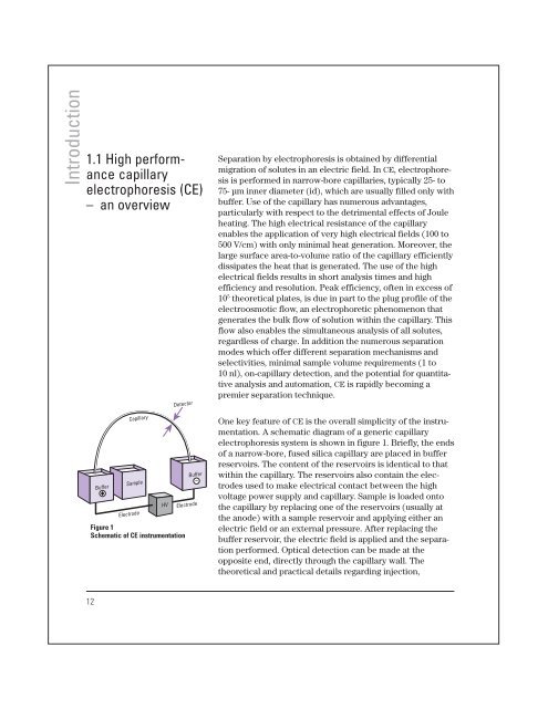
Figure 1<br />
Schematic of CE instrumentation<br />
Separation by <strong>electrophoresis</strong> is obtained by differential<br />
migration of solutes in an electric field. In CE, <strong>electrophoresis</strong><br />
is performed in narrow-bore capillaries, typically 25- to<br />
75- µm inner diameter (id), which are usually filled only with<br />
buffer. Use of the <strong>capillary</strong> has numerous advantages,<br />
particularly with respect to the detrimental effects of Joule<br />
heating. The high electrical resistance of the <strong>capillary</strong><br />
enables the application of very high electrical fields (100 to<br />
500 V/cm) with only minimal heat generation. Moreover, the<br />
large surface area-to-volume ratio of the <strong>capillary</strong> efficiently<br />
dissipates the heat that is generated. The use of the high<br />
electrical fields results in short analysis times and high<br />
efficiency and resolution. Peak efficiency, often in excess of<br />
10 5 theoretical plates, is due in part to the plug profile of the<br />
electroosmotic flow, an electrophoretic phenomenon that<br />
generates the bulk flow of solution within the <strong>capillary</strong>. This<br />
flow also enables the simultaneous analysis of all solutes,<br />
regardless of charge. In addition the numerous separation<br />
modes which offer different separation mechanisms and<br />
selectivities, minimal sample volume requirements (1 to<br />
10 nl), on-<strong>capillary</strong> detection, and the potential for quantitative<br />
analysis and automation, CE is rapidly becoming a<br />
premier separation technique.<br />
One key feature of CE is the overall simplicity of the instrumentation.<br />
A schematic diagram of a generic <strong>capillary</strong><br />
<strong>electrophoresis</strong> system is shown in figure 1. Briefly, the ends<br />
of a narrow-bore, fused silica <strong>capillary</strong> are placed in buffer<br />
reservoirs. The content of the reservoirs is identical to that<br />
within the <strong>capillary</strong>. The reservoirs also contain the electrodes<br />
used to make electrical contact between the high<br />
voltage power supply and <strong>capillary</strong>. Sample is loaded onto<br />
the <strong>capillary</strong> by replacing one of the reservoirs (usually at<br />
the anode) with a sample reservoir and applying either an<br />
electric field or an external pressure. After replacing the<br />
buffer reservoir, the electric field is applied and the separation<br />
performed. Optical detection can be made at the<br />
opposite end, directly through the <strong>capillary</strong> wall. The<br />
theoretical and practical details regarding injection,<br />
12