Mancini, E.A. and others, 2004, Integrated geologic‑engineering
Mancini, E.A. and others, 2004, Integrated geologic‑engineering
Mancini, E.A. and others, 2004, Integrated geologic‑engineering

Create successful ePaper yourself
Turn your PDF publications into a flip-book with our unique Google optimized e-Paper software.
Report Title<br />
“<strong>Integrated</strong> Geologic-Engineering Model for Reef <strong>and</strong> Carbonate Shoal Reservoirs Associated<br />
with Paleohighs: Upper Jurassic Smackover Formation, Northeastern Gulf of Mexico”<br />
Type of Report<br />
Final Project Report<br />
Reporting Period Start Date<br />
September 1, 2000<br />
Reporting Period End Date<br />
December 31, 2003<br />
Principal Author<br />
Ernest A. <strong>Mancini</strong> (205/348-4319)<br />
Department of Geological Sciences<br />
Box 870338<br />
202 Bevill Building<br />
University of Alabama<br />
Tuscaloosa, AL 35487-0338<br />
Date Report was Issued<br />
February 25, <strong>2004</strong><br />
DOE Award Number<br />
DE-FC26-00BC15303<br />
Name <strong>and</strong> Address of Participants<br />
Ernest A. <strong>Mancini</strong><br />
Dept. of Geological Sciences<br />
Box 870338<br />
Tuscaloosa, AL 35487-0338<br />
Robert D. Schneeflock, Jr.<br />
Paramount Petroleum Co., Inc.<br />
230 Christopher Cove<br />
Ridgel<strong>and</strong>, MS 39157<br />
Bruce S. Hart<br />
Earth & Planetary Sciences<br />
McGill University<br />
3450 University St.<br />
Montreal, Quebec H3A 2A7<br />
CANADA<br />
Richard K. Strahan<br />
Strago Petroleum Corporation<br />
811 Dallas St., Suite 1407<br />
Houston, TX 77002<br />
Thomas Blasingame<br />
Dept. of Petroleum Engineering<br />
Texas A&M University<br />
College Station, TX 77843-3116<br />
Roger M. Chapman<br />
Longleaf Energy Group, Inc.<br />
319 Belleville Ave.<br />
Brewton, AL 36427<br />
i
Disclaimer<br />
This report was prepared as an account of work sponsored by an agency of the United<br />
States Government. Neither the United States Government nor any agency thereof, nor<br />
any of their employees, makes any warranty, express or implied, or assumes any legal<br />
liability or responsibility for the accuracy, completeness, or usefulness of any<br />
information, apparatus, product, or process disclosed, or represents that its use would not<br />
infringe privately owned rights. Reference herein to any specific commercial product,<br />
process, or service by trade name, trademark, manufacturer, or otherwise does not<br />
necessarily constitute or imply its endorsement, recommendation, or favoring by the<br />
United States Government or any agency thereof. The views <strong>and</strong> opinions of authors<br />
expressed herein do not necessarily state or reflect those of the United States Government<br />
or any agency thereof.<br />
ii
<strong>Integrated</strong> Geologic-Engineering Model for Reef <strong>and</strong> Carbonate Shoal<br />
Reservoirs Associated with Paleohighs: Upper Jurassic Smackover<br />
Formation, Northeastern Gulf of Mexico<br />
Final Report<br />
February 25, <strong>2004</strong><br />
By:<br />
Ernest A. <strong>Mancini</strong><br />
Joe Benson<br />
Thomas Blasingame<br />
Wayne Ahr<br />
Rosalind Archer<br />
Bruce Hart<br />
Juan Carlos Llinas<br />
William Parcell<br />
Brian Panetta<br />
Dylan Morgan<br />
Juliana Tebo<br />
Roger Chapman<br />
Robert Schneeflock<br />
Richard Strahan<br />
Work Performed Under Contract No. DE-FC26-00BC15303<br />
University of Alabama<br />
Tuscaloosa, Alabama<br />
National Energy Technology Laboratory<br />
National Petroleum Technology Office<br />
U.S. DEPARTMENT OF ENERGY<br />
Tulsa, Oklahoma
ABSTRACT<br />
The University of Alabama, in cooperation with Texas A&M University, McGill University,<br />
Longleaf Energy Group, Strago Petroleum Corporation, <strong>and</strong> Paramount Petroleum Company, has<br />
undertaken an integrated, interdisciplinary geoscientific <strong>and</strong> engineering research project. The<br />
project is designed to characterize <strong>and</strong> model reservoir architecture, pore systems <strong>and</strong> rock-fluid<br />
interactions at the pore to field scale in Upper Jurassic Smackover reef <strong>and</strong> carbonate shoal<br />
reservoirs associated with varying degrees of relief on pre-Mesozoic basement paleohighs in the<br />
northeastern Gulf of Mexico. The project effort includes the prediction of fluid flow in carbonate<br />
reservoirs through reservoir simulation modeling which utilizes geologic reservoir<br />
characterization <strong>and</strong> modeling <strong>and</strong> the prediction of carbonate reservoir architecture,<br />
heterogeneity <strong>and</strong> quality through seismic imaging.<br />
The primary goal of the project is to increase the profitability, producibility <strong>and</strong> efficiency<br />
of recovery of oil from existing <strong>and</strong> undiscovered Upper Jurassic fields characterized by reef <strong>and</strong><br />
carbonate shoals associated with pre-Mesozoic basement paleohighs.<br />
Geoscientific reservoir property, geophysical seismic attribute, petrophysical property, <strong>and</strong><br />
engineering property characterization has shown that reef (thrombolite) <strong>and</strong> shoal reservoir<br />
lithofacies developed on the flanks of high-relief crystalline basement paleohighs (Vocation<br />
Field example) <strong>and</strong> on the crest <strong>and</strong> flanks of low-relief crystalline basement paleohighs<br />
(Appleton Field example). The reef thrombolite lithofacies have higher reservoir quality than<br />
the shoal lithofacies due to overall higher permeabilities <strong>and</strong> greater interconnectivity.<br />
Thrombolite dolostone flow units, which are dominated by dolomite intercrystalline <strong>and</strong> vuggy<br />
pores, are characterized by a pore system comprised of a higher percentage of large-sized pores<br />
<strong>and</strong> larger pore throats.<br />
iii
Rock-fluid interactions (diagenesis) studies have shown that although the primary control on<br />
reservoir architecture <strong>and</strong> geographic distribution of Smackover reservoirs is the fabric <strong>and</strong><br />
texture of the depositional lithofacies, diagenesis (chiefly dolomitization) is a significant factor<br />
that preserves <strong>and</strong> enhances reservoir quality. The evaporative pumping mechanism is favored<br />
to explain the dolomitization of the thrombolite doloboundstone <strong>and</strong> dolostone reservoir flow<br />
units at Appleton <strong>and</strong> Vocation Fields.<br />
Geologic modeling, reservoir simulation, <strong>and</strong> the testing <strong>and</strong> applying the resulting<br />
integrated geologic–engineering models have shown that little oil remains to be recovered at<br />
Appleton Field <strong>and</strong> a significant amount of oil remains to be recovered at Vocation Field through<br />
a strategic infill drilling program. The drive mechanisms for primary production in Appleton<br />
<strong>and</strong> Vocation Fields remain effective; therefore, the initiation of a pressure maintenance program<br />
or enhanced recovery project is not required at this time.<br />
The integrated geologic-engineering model developed for a low-relief paleohigh (Appleton<br />
Field) was tested for three scenarios involving the variables of present-day structural elevation<br />
<strong>and</strong> the presence/absence of potential reef thrombolite lithofacies. In each case, the predictions<br />
based upon the model were correct. From this modeling, the characteristics of the ideal prospect<br />
in the basement ridge play include a low-relief paleohigh associated with dendroidal/chaotic<br />
thrombolite doloboundstone <strong>and</strong> dolostone that has sufficient present-day structural relief so that<br />
these carbonates rest above the oil-water contact. Such a prospect was identified from the<br />
modeling, <strong>and</strong> it is located northwest of well Permit # 3854B (Appleton Field) <strong>and</strong> south of well<br />
# Permit #11030B (Northwest Appleton Field).<br />
iv
Table of Contents<br />
Page<br />
Title Page ............................................................................................................................<br />
Disclaimer ..........................................................................................................................<br />
Abstract ..............................................................................................................................<br />
Table of Contents ...............................................................................................................<br />
i<br />
ii<br />
iii<br />
v<br />
Introduction ........................................................................................................................ 1<br />
Executive Summary ........................................................................................................... 9<br />
Experimental Results ......................................................................................................... 14<br />
Geoscientific Reservoir Characterization ................................................................... 14<br />
Geophysical Seismic Attribute Characterization ......................................................... 68<br />
Petrophysical Property Characterization .................................................................... 131<br />
Engineering Property Characterization ...................................................................... 187<br />
Rock-Fluid Interactions (Diagenesis) ........................................................................... 284<br />
Geologic Modeling ...................................................................................................... 295<br />
Reservoir Simulation .................................................................................................. 311<br />
Testing <strong>and</strong> Applying <strong>Integrated</strong> Geologic-Engineering Models …............................. 348<br />
Technology Transfer ............................................................................................... 359<br />
Discussion ........................................................................................................................ 369<br />
Conclusions ........................................................................................................................ 412<br />
References .......................................................................................................................... 417<br />
v
INTRODUCTION<br />
The University of Alabama, in cooperation with Texas A&M University, McGill University,<br />
Longleaf Energy Group, Strago Petroleum Corporation, <strong>and</strong> Paramount Petroleum Company, has<br />
undertaken an integrated, interdisciplinary geoscientific <strong>and</strong> engineering research project. The<br />
project is designed to characterize <strong>and</strong> model reservoir architecture, pore systems <strong>and</strong> rock-fluid<br />
interactions at the pore to field scale in Upper Jurassic Smackover reef <strong>and</strong> carbonate shoal<br />
reservoirs associated with varying degrees of relief on pre-Mesozoic basement paleohighs in the<br />
northeastern Gulf of Mexico. The project effort includes the prediction of fluid flow in carbonate<br />
reservoirs through reservoir simulation modeling that utilizes geologic reservoir characterization<br />
<strong>and</strong> modeling <strong>and</strong> the prediction of carbonate reservoir architecture, heterogeneity <strong>and</strong> quality<br />
through seismic imaging.<br />
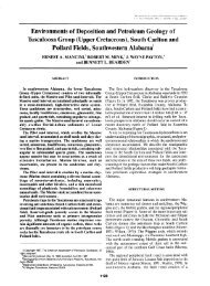
The Upper Jurassic Smackover Formation (Figure 1) is one of the most productive<br />
hydrocarbon reservoirs in the northeastern Gulf of Mexico. Production from Smackover<br />
carbonates totals 1 billion barrels of oil <strong>and</strong> 4 trillion cubic feet of natural gas. The production is<br />
from three plays: 1) basement ridge play, 2) regional peripheral fault play, <strong>and</strong> 3) salt anticline<br />
play (Figure 2). Unfortunately, much of the oil in the Smackover fields in these plays remains<br />
unrecovered because of a poor underst<strong>and</strong>ing of the rock <strong>and</strong> fluid characteristics that affects our<br />
underst<strong>and</strong>ing of reservoir architecture, heterogeneity, quality, fluid flow <strong>and</strong> producibility. This<br />
scenario is compounded because of inadequate techniques for reservoir detection <strong>and</strong> the<br />
characterization of rock-fluid interactions, as well as imperfect models for fluid flow prediction.<br />
This poor underst<strong>and</strong>ing is particularly illustrated for the case with Smackover fields in the<br />
basement ridge play (Figure 3) where independent producers dominate the development <strong>and</strong><br />
management of these fields. These producers do not have the financial resources <strong>and</strong>/or staff
Figure 1. Jurassic stratigraphy in the study area.<br />
2
Figure 2. Major petroleum trends in study area.<br />
3
4<br />
Figure 3. Location of Appleton <strong>and</strong> Northwest Appleton <strong>and</strong> Vocation <strong>and</strong> South Vocation<br />
Fields.
5<br />
expertise to substantially improve the underst<strong>and</strong>ing of the geoscientific <strong>and</strong> engineering factors<br />
affecting the producibility of Smackover carbonate reservoirs, which makes research <strong>and</strong><br />
application of new technologies for reef-shoal reservoirs all that more important <strong>and</strong> urgent. The<br />
research results from studying the fields identified for this project will be of direct benefit to<br />
these producers.<br />
This interdisciplinary project is a 3-year effort to characterize, model <strong>and</strong> simulate fluid<br />
flow in carbonate reservoirs <strong>and</strong> consists of 3 phases <strong>and</strong> 11 tasks. Phase 1 (1 year) of the project<br />
involves geoscientific reservoir characterization, rock-fluid interactions, petrophysical <strong>and</strong><br />
engineering property characterization, <strong>and</strong> data integration. Phase 2 (1.5 years) includes geologic<br />
modeling <strong>and</strong> reservoir simulation. Phase 3 (0.5 year) involves building the geologic-engineering<br />
model, testing the geologic-engineering model, <strong>and</strong> applying the geologic-engineering model.<br />
The principal goal of this project is to assist independent producers in increasing oil<br />
producibility from reef <strong>and</strong> shoal reservoirs associated with pre-Mesozoic paleotopographic<br />
features through an interdisciplinary geoscientific <strong>and</strong> engineering characterization <strong>and</strong> modeling<br />
of carbonate reservoir architecture, heterogeneity, quality <strong>and</strong> fluid flow from the pore to field<br />
scale.<br />
The objectives of the project are as follows:<br />
1. Evaluate the geological, geophysical, petrophysical, <strong>and</strong> engineering properties of reef-shoal<br />
reservoirs emphasizing Appleton (Figure 4) <strong>and</strong> Vocation (Figure 5) Fields.<br />
2. Construct a digital database of integrated geoscience <strong>and</strong> engineering data for reef-shoal<br />
carbonate reservoirs associated with basement paleohighs.
Figure 4. Appleton Field Unit area.<br />
6
Figure 5. Vocation Field area.<br />
7
8<br />
3. Develop an integrated geologic models, based on geological, geophysical, petrophysical <strong>and</strong><br />
engineering data <strong>and</strong> analysis for improving reservoir detection, reservoir characterization,<br />
reservoir imaging, flow simulation, <strong>and</strong> performance prediction for reef-shoal carbonate<br />
reservoirs using the case studies of Appleton <strong>and</strong> Vocation Fields.<br />
4. Test <strong>and</strong> apply the integrated geologic models on prospective Smackover reef-shoal<br />
reservoirs associated with basement paleohighs.<br />
This project has direct <strong>and</strong> significant economic benefits because the Smackover is a prolific<br />
hydrocarbon reservoir in the northeastern Gulf of Mexico. Smackover reefs represent an<br />
underdeveloped reservoir, <strong>and</strong> the basement ridge play in which these reefs are associated<br />
represents an underexplored play. Initial estimations indicate the original oil resource target<br />
available in this play approximates 90 million barrels. To date, 30 million barrels of oil have<br />
been produced from 54 fields. Any newly discovered fields are expected to have 1 to 3 million<br />
barrels of oil in recovery potential. The combined oil production from the Smackover fields<br />
(Appleton <strong>and</strong> Vocation Fields) studied in this project total 5 million barrels of oil. The results<br />
from this project should lead to increased oil producibility from existing <strong>and</strong> newly discovered<br />
fields similar to Appleton <strong>and</strong> Vocation Fields. Production of these domestic resources will serve<br />
to reduce U.S. dependence on foreign oil supplies.<br />
Completion of the project will contribute significantly to the underst<strong>and</strong>ing of: the geologic<br />
factors controlling reef <strong>and</strong> shoal development on paleohighs, carbonate reservoir architecture<br />
<strong>and</strong> heterogeneity at the pore to field scale, generalized rock-fluid interactions <strong>and</strong> alterations in<br />
carbonate reservoirs, the geological <strong>and</strong> geophysical attributes important to geologic modeling of<br />
reef-shoal carbonate reservoirs, the critical factors affecting fluid flow in carbonate reservoirs,<br />
the elements important to the development of a carbonate integrated geologic model, <strong>and</strong> the
9<br />
geological, geophysical, <strong>and</strong>/or petrophysical properties important to improved carbonate<br />
reservoir detection, characterization, imaging <strong>and</strong> flow prediction.<br />
EXECUTIVE SUMMARY<br />
The University of Alabama, in cooperation with Texas A&M University, McGill University,<br />
Longleaf Energy Group, Strago Petroleum Corporation, <strong>and</strong> Paramount Petroleum Company, has<br />
undertaken an integrated, interdisciplinary geoscientific <strong>and</strong> engineering research project. The<br />
project is designed to characterize <strong>and</strong> model reservoir architecture, pore systems <strong>and</strong> rock-fluid<br />
interactions at the pore to field scale in Upper Jurassic Smackover reef <strong>and</strong> carbonate shoal<br />
reservoirs associated with varying degrees of relief on pre-Mesozoic basement paleohighs in the<br />
northeastern Gulf of Mexico. The project effort includes the prediction of fluid flow in carbonate<br />
reservoirs through reservoir simulation modeling which utilizes geologic reservoir<br />
characterization <strong>and</strong> modeling <strong>and</strong> the prediction of carbonate reservoir architecture,<br />
heterogeneity <strong>and</strong> quality through seismic imaging.<br />
The project has direct <strong>and</strong> significant economic benefits because the Smackover is a prolific<br />
hydrocarbon reservoir in the northeastern Gulf of Mexico. To date, 30 million barrels of oil have<br />
been produced from 54 fields that have been discovered <strong>and</strong> developed in the basement ridge<br />
play. Smackover reef <strong>and</strong> carbonate facies associated with paleohighs in this play represent<br />
underdeveloped reservoirs. The combined oil production from the Smackover fields (Appleton<br />
<strong>and</strong> Vocation Fields) studied in this project total 5 million barrels of oil. The results from this<br />
project should lead to increased oil producibility from existing <strong>and</strong> newly discovered fields<br />
similar to Appleton <strong>and</strong> Vocation Fields.
10<br />
The primary goal of the project is to increase the profitability, producibility <strong>and</strong> efficiency<br />
of recovery of oil from existing <strong>and</strong> undiscovered Upper Jurassic fields characterized by reef <strong>and</strong><br />
carbonate shoals associated with pre-Mesozoic basement paleohighs.<br />
The objectives of the project are: (1) to evaluate the geological, geophysical, petrophysical<br />
<strong>and</strong> engineering properties of reef-shoal reservoirs using Appleton <strong>and</strong> Vocation Fields as case<br />
studies; (2) construct a digital database of integrated geoscience <strong>and</strong> engineering data for reefshoal<br />
reservoirs associated with basement paleohighs; (3) develop integrated geologic models,<br />
based on geological, geophysical, petrophysical, <strong>and</strong> engineering data <strong>and</strong> analysis, for<br />
improving reservoir detection, characterization, imaging, flow simulation <strong>and</strong> performance<br />
prediction for reef-shoal reservoirs using the case studies of Appleton <strong>and</strong> Vocation Fields; <strong>and</strong><br />
(4) test <strong>and</strong> apply the integrated geologic models to prospective Smackover reef-shoal reservoirs<br />
associated with basement paleohighs.<br />
The objectives have been achieved through the accomplishments resulting from the<br />
following research tasks: geoscientific reservoir property characterization, geophysical seismic<br />
attribute characterization, petrophysical property characterization, engineering property<br />
characterization, rock-fluid interactions (diagenesis), geologic modeling, reservoir simulation,<br />
testing <strong>and</strong> applying the integrated geologic–engineering models, <strong>and</strong> technology transfer.<br />
Geoscientific reservoir property characterization has shown that the main Smackover<br />
lithofacies are subtidal, reef flank, reef crest, shoal flank, shoal crest, lagoon, tidal flat <strong>and</strong><br />
sabkha. The reef lithofacies consist of thrombolite layered, chaotic <strong>and</strong> dendroidal subfacies.<br />
The shoal complex consists of the lagoon/subtidal <strong>and</strong> shoal flank <strong>and</strong> crest lithofacies. These<br />
reef <strong>and</strong> shoal reservoir lithofacies are developed on the flanks of high-relief crystalline
11<br />
basement paleohighs (Vocation Field example) <strong>and</strong> on the crest <strong>and</strong> flanks of low-relief<br />
crystalline basement paleohighs (Appleton Field example).<br />
Seismic attribute characterization has shown that seismic attributes can be used to predict<br />
subsurface rock properties, such as the presence/absence of porosity <strong>and</strong> porosity thickness in the<br />
Smackover reservoir lithofacies, associated with basement paleohighs. Porous intervals were<br />
generally greater <strong>and</strong> thicker on the flanks of the paleohighs, rather than the crests of these<br />
features, due to greater accommodation space <strong>and</strong> improved growth conditions for reef<br />
organisms. This volume-based seismic attribute study was also used to determine lithofacies<br />
distribution <strong>and</strong> thickness <strong>and</strong> to define the vertical <strong>and</strong> lateral heterogeneity in Smackover<br />
reservoirs.<br />
Petrophysical property characterization has shown that the shoal <strong>and</strong> reef thrombolite<br />
lithofacies are the main reservoir lithofacies. The reservoir quality of the thrombolite lithofacies<br />
is greater than the shoal lithofacies because the thrombolite reservoir consists of a pore system<br />
comprised of a higher percentage of large-sized pores <strong>and</strong> larger pore throats. The shoal pore<br />
system is dominated by moldic <strong>and</strong> dolomite intercrystalline pores. The dendroidal <strong>and</strong> chaotic<br />
thrombolite reservoirs have higher producibility than the layered thrombolite reservoirs because<br />
they have overall higher permeabilities <strong>and</strong> greater interconnectivity due to their vertical <strong>and</strong><br />
horizontal branching growth pattern. Thrombolite flow units are characterized by dolomite<br />
intercrystalline <strong>and</strong> vuggy pores.<br />
Engineering property characterization has shown that reservoirs at Appleton <strong>and</strong> Vocation<br />
Fields have a heterogeneous nature. Porosity <strong>and</strong> permeability data show that the reef reservoirs<br />
are of higher quality than the shoal reservoirs. The primary production mechanism in Vocation<br />
Field is a combination drive consisting of fluid/rock/gas expansion <strong>and</strong> water from an underlying
12<br />
<strong>and</strong>/or adjoining aquifer. The primary production mechanism in Appleton Field is a strong<br />
bottom up water drive. New well pressure test data acquired for Appleton Field show that the<br />
reservoir pressures at Appleton Field currently range from 4423 to 5125 psia.<br />
Rock-fluid interactions (diagenesis) studies show that although the primary control on<br />
reservoir architecture <strong>and</strong> geographic distribution of Smackover reservoirs is the fabric <strong>and</strong><br />
texture of the depositional lithofacies, diagenesis (chiefly dolomitization) is a significant factor<br />
that preserves <strong>and</strong> enhances reservoir quality. Porosity in the thrombolite doloboundstone<br />
lithofacies is a mixture of primary shelter <strong>and</strong> fenestral porosity overprinted by secondary<br />
dolomite intercrystalline <strong>and</strong> vuggy porosity. Porosity in the shoal dolograinstone lithofacies is<br />
primary interparticle porosity overprinted by secondary moldic <strong>and</strong> dolomite intercrystalline.<br />
Although seepage reflux <strong>and</strong> mixing zone diagenetic processes are mechanisms for the formation<br />
of Smackover dolostone, the evaporative pumping mechanism is favored to explain the intense<br />
<strong>and</strong> extensive dolomitization of the Appleton <strong>and</strong> Vocation reservoir flow units.<br />
Geologic modeling of the Appleton <strong>and</strong> Vocation paleohighs <strong>and</strong> associated lithofacies has<br />
shown that these features are complex structures. The structure at Appleton Field is a northwestsoutheast<br />
trending, low-relief composite paleotopographic high with two water levels. The well<br />
production differences in the field are related to the heterogenous nature of the reservoirs. The<br />
greater production from the eastern part of the composite paleohigh is attributed to the higher<br />
relief, which results in the placement of more thrombolite dolostone above the oil-water contact.<br />
The structure at Vocation Field is a high-relief composite paleotopographic high with multiple<br />
water levels. This composite feature consists of one main north-south oriented elongated feature<br />
with three crests that remained subaerially exposed throughout the time of Smackover<br />
deposition. The Vocation structure is bounded to the east <strong>and</strong> north by high-angle normal faults.
13<br />
Reef growth was limited to the eastern <strong>and</strong> northern flanks (leeward side) of the structure due to<br />
Smackover paleoenvironmental conditions.<br />
Reservoir simulation of the reservoirs at Appleton <strong>and</strong> Vocation Fields used the 3-D<br />
geologic models for these reservoirs as a foundation for the simulation modeling. Reservoir<br />
simulation at Appleton Field shows that 50% of the recoverable oil in this field has been<br />
produced; thus, little oil remains to be recovered. Of the oil remaining, the areas around well<br />
Permits #3854B, #6247 <strong>and</strong> #4735B (western part of the structure) have the most potential to<br />
recover additional oil. Reservoir simulation at Vocation Field shows that a significant amount of<br />
oil remains to be recovered in this field through infill drilling. The area north of well Permit<br />
#4786B <strong>and</strong> south of well Permits #1638 <strong>and</strong> #1691 <strong>and</strong> the area southeast of well Permits<br />
#1599 <strong>and</strong> #3412 <strong>and</strong> northwest of well Permit #3739 have high potential for recovering<br />
additional oil from this field.<br />
The integrated geologic-engineering model developed for a low-relief paleohigh (Appleton<br />
Field) was tested using three scenarios involving the variables of present-day structural elevation<br />
<strong>and</strong> the presence or absence of potential reef thrombolite lithofacies. In each case, the<br />
predictions based upon the model were correct. The integrated model was also used to evaluate<br />
existing reservoir management strategies at Appleton <strong>and</strong> Vocation Fields. It was concluded that<br />
the drive mechanisms for primary production in these fields remain effective; <strong>and</strong> therefore, no<br />
recommendations for the initiation of a pressure maintenance program or an enhanced recovery<br />
project were justified at this time. It was determined that these fields would benefit from<br />
additional infill drilling, particularly Vocation Field, at the strategic drill sites identified from the<br />
reservoir simulation modeling. From the integrated geologic model, a drill site northwest of well<br />
Permit #3854B (Appleton Field) <strong>and</strong> south of well Permit #11030B (Northwest Appleton Field)
14<br />
was identified as a location with high potential to encounter thrombolite doloboundstone <strong>and</strong><br />
dolostone on a low-relief paleohigh.<br />
To date, technology transfer activities have included conducting two technology workshops<br />
in Jackson, Mississippi, making 31 technical presentations at regional <strong>and</strong> national meetings, <strong>and</strong><br />
publishing 40 technical publications on the research results from this project.<br />
EXPERIMENTAL RESULTS<br />
Geoscientific Reservoir Characterization.--This task was designed to characterize<br />
reservoir architecture, pore systems <strong>and</strong> heterogeneity based on geological <strong>and</strong> geophysical<br />
properties. This work has been done using well logs, cores, <strong>and</strong> other data for Vocation Field <strong>and</strong><br />
for Appleton Field. The first phase of the task involved core descriptions, including lithologies,<br />
sedimentary structures, lithofacies, depositional environments, systems tracts, <strong>and</strong> depositional<br />
sequences. Graphic logs were constructed from the core studies depicting the information<br />
described above. Core samples were selected for petrographic, XRD, <strong>and</strong> microprobe analyses.<br />
The graphic logs were compared to available core analysis <strong>and</strong> well log data. The core features<br />
<strong>and</strong> core analyses were calibrated to the well log patterns. The next phase was the link between<br />
core <strong>and</strong> well log analysis <strong>and</strong> reservoir modeling. It involved the preparation of stratigraphic<br />
<strong>and</strong> structural cross sections to illustrate structural growth, lithofacies <strong>and</strong> reservoir geometry,<br />
<strong>and</strong> depositional systems tract distribution. Maps were prepared to illustrate lithofacies<br />
distribution, stratigraphic <strong>and</strong> reservoir interval thickness (isolith <strong>and</strong> isopach maps), <strong>and</strong> stratal<br />
structural configurations. These cross sections <strong>and</strong> maps, in association with the core<br />
descriptions, were utilized to make sequence stratigraphic, environment of deposition, <strong>and</strong><br />
structural interpretations. St<strong>and</strong>ard industry software, such as StratWorks <strong>and</strong> Z-Map, were used<br />
in the preparation of the cross sections <strong>and</strong> subsurface maps. The next phase included
15<br />
identification <strong>and</strong> quantification of carbonate mineralogy <strong>and</strong> textures (grain, matrix <strong>and</strong> cement<br />
types), pore topology <strong>and</strong> geometry, <strong>and</strong> percent of porosity <strong>and</strong> was performed to support <strong>and</strong><br />
enhance the visual core descriptions. These petrographic, XRD <strong>and</strong> microprobe analyses were<br />
used to confirm <strong>and</strong> quantify the observations made in the core descriptions. This analysis<br />
provides the opportunity to study reservoir architecture <strong>and</strong> heterogeneity at the microscopic<br />
scale. The last phase involved the study of pore systems in the reservoir, including pore types<br />
<strong>and</strong> throats. This phase examined pore shape <strong>and</strong> geometry <strong>and</strong> the nature <strong>and</strong> distribution of<br />
pore throats to determine the features of the pore systems that are affecting reservoir<br />
producibility. The geoscientific characterization of the Smackover at Appleton <strong>and</strong> Vocation<br />
Fields has been done by <strong>Mancini</strong>, Benson, Llinas, Parcell <strong>and</strong> Panetta at the University of<br />
Alabama. This work is part of the dissertation research of Llinas.<br />
The architecture <strong>and</strong> heterogeneities of reservoirs that are a product of a shallow marine<br />
carbonate setting are very complex <strong>and</strong> a challenge technically to predict. Carbonate systems are<br />
greatly influenced by biological <strong>and</strong> chemical processes in addition to physical processes of<br />
deposition <strong>and</strong> compaction. Carbonate sedimentation rates are primarily a result of the<br />
productivity of marine organisms in subtidal environments. In particular, reef-forming organisms<br />
are a crucial component to the carbonate system because of their ability to modify the<br />
surrounding environments. Reef growth is dependent upon many environmental factors, but one<br />
crucial factor is sea-floor relief (paleotopography). In addition, the development of a reef<br />
structure contributes to depositional topography. Further, the susceptibility of carbonates to<br />
alteration by early to late diagenetic processes dramatically impacts reservoir heterogeneity.<br />
Reservoir characterization <strong>and</strong> the quantification of heterogeneity, therefore, becomes a major<br />
task because of the physiochemical <strong>and</strong> biological origins of carbonates <strong>and</strong> because of the
16<br />
masking of the depositional rock fabric <strong>and</strong> reservoir architecture due to dissolution,<br />
dolomitization, <strong>and</strong> cementation. Further, the detection, imaging, <strong>and</strong> prediction of carbonate<br />
reservoir heterogeneity <strong>and</strong> producibility is difficult because of an incomplete underst<strong>and</strong>ing of<br />
the lithologic characteristics <strong>and</strong> fluid-rock dynamics that affect log response <strong>and</strong> geophysical<br />
attributes.<br />
Appleton Field. All available whole cores (11) from Appleton Field have been described<br />
<strong>and</strong> thin sections (379) from these cores have been studied. Graphic logs were constructed<br />
describing each of the cores (Figures 6 through 16). Depositional facies were determined from<br />
the core descriptions. From the study of thin sections, the petrographic characteristics of these<br />
lithofacies have been described, <strong>and</strong> the pore systems inherent to these facies have been<br />
identified (Table 1). The core data <strong>and</strong> well log signatures have been integrated <strong>and</strong> calibrated on<br />
these graphic logs.<br />
For Appleton Field (Figure 4), the well log <strong>and</strong> core data have been entered into a digital<br />
database <strong>and</strong> structural maps on top of the basement (Figure 17), reef (Figure 18), <strong>and</strong><br />
Smackover/Buckner (Figure 19) have been constructed. An isopach map of the Smackover<br />
interval has been prepared (Figure 20), <strong>and</strong> thickness maps of the sabkha facies (Figure 21), tidal<br />
flat facies (Figure 22), shoal complex (Figure 23), tidal flat/shoal complex (Figure 24) <strong>and</strong> reef<br />
complex (Figure 25) facies have been constructed. A cross section (Figure 26) illustrating the<br />
thickness <strong>and</strong> facies changes across Appleton Field has been prepared.<br />
Based on the description of cores (11) <strong>and</strong> thin sections (379), 14 lithofacies have been<br />
identified in the Smackover/Buckner at Appleton Field. Analysis of the vertical <strong>and</strong> lateral<br />
distributions of these lithofacies indicates that these lithofacies were deposited in one or more of<br />
eight depositional environments: 1) subtidal, 2) reef flank, 3) reef crest, 4) shoal flank, 5) shoal
17<br />
crest, 6) lagoon, 7) tidal flat, <strong>and</strong> 8) sabkha in a transition from a catch-up carbonate system to a<br />
keep-up carbonate system. These paleoenvironments have been assigned to four<br />
Smackover/Buckner genetic depositional systems for three-dimensional stratigraphic modeling.<br />
Each of these systems has been interpreted as being time-equivalent from that work, two<br />
principal reservoir facies, reef <strong>and</strong> shoal were identified at Appleton Field.<br />
Based on the description of cores <strong>and</strong> thin sections, three subfacies have been recognized in<br />
the reef facies. These subfacies include thrombolitic layered, chaotic <strong>and</strong> dendroidal. Each<br />
represents a different <strong>and</strong> distinct microbial growth form which has inherent properties that<br />
affect reservoir architecture, pore systems, <strong>and</strong> heterogeneity. The layered growth form is<br />
characterized by a reservoir architecture that is characterized by lateral continuity <strong>and</strong> high<br />
vertical heterogeneity. The chaotic form has a reservoir architecture that is characterized by high<br />
vertical <strong>and</strong> lateral continuity. The dendroidal form has a reservoir architecture that is<br />
characterized by high vertical <strong>and</strong> moderate lateral continuity <strong>and</strong> moderate heterogeneity. The<br />
pore systems in each of these reservoir fabrics consist of shelter <strong>and</strong> enlarged pore types. The<br />
enlargement of these primary pores is due to dissolution <strong>and</strong> dolomitization resulting in a vuggy<br />
appearing pore system. Three subfacies have been recognized in the shoal facies. These<br />
subfacies are the lagoon/subtidal, shoal flank, <strong>and</strong> shoal crest. The lagoon/subtidal subfacies has<br />
a mud-supported architecture <strong>and</strong> therefore is not considered a reservoir. The shoal flank has a<br />
grain-supported architecture but has considerable carbonate mud associated with it, <strong>and</strong><br />
therefore, has low to moderate reservoir capacity. The shoal crest has a grain-supported<br />
architecture with minimal carbonate mud, <strong>and</strong> therefore, has the highest reservoir capacity of the<br />
shoal subfacies. The pore systems of the shoal flank <strong>and</strong> shoal crest reservoir facies consist of<br />
intergranular <strong>and</strong> enlarged pore types. The enlargement of the primary pores is due to dissolution
18<br />
<strong>and</strong> dolomitization. Heterogeneity in the shoal reservoir is high due to the rapid lateral <strong>and</strong><br />
vertical changes in this depositional environment. Graphic logs were constructed for each of the<br />
cores. The core data <strong>and</strong> well log signatures are integrated <strong>and</strong> calibrated on these graphic logs.<br />
Appleton Field was discovered in 1983 with the drilling of the D.W. McMillan 2-14 well<br />
(Permit #3854). The discovery well was drilled off the crest of a composite paleotopographic<br />
structure, based on 2-D seismic <strong>and</strong> well data. The well penetrated Paleozoic basement rock at a<br />
depth of 12,786 feet. The petroleum trap at Appleton was interpreted to be a simple anticline<br />
associated with a northwest-southeast trending basement paleohigh. After further drilling in the<br />
field, the Appleton structure was interpreted as an anticline consisting of two local paleohighs.<br />
The D.W. McMillan 2-15 well (Permit #6247) was drilled in 1991. The drilling of this well<br />
resulted in the structural interpretation being revised to consist of three local paleohighs. In<br />
1995, 3-D seismic reflection data were obtained for the Appleton Field area. The interpretation<br />
of these data indicated three local highs with the western paleohigh being separated into a<br />
western <strong>and</strong> a central feature.<br />
Based on the structural maps that we have prepared for the Appleton Field, we have<br />
concluded that the Appleton structure is a low-relief, northwest-southeast trending ridge<br />
comprised of local paleohighs. This interpretation is based on the construction of structure maps<br />
on top of the basement, on top of the reef, <strong>and</strong> on top of the Smackover/Buckner from well log<br />
data <strong>and</strong> 3-D seismic data.<br />
The Smackover reservoir at Appleton Field has been influenced by antecedent<br />
paleotopography. The Smackover thickness ranges from 177 feet in the McMillan 2-14 well<br />
(Permit #3854) to 228 feet in the McMillan Trust 11-1 well (Permit #3986) in the field. As<br />
observed from the cross sections based on well log data <strong>and</strong> on seismic data, the sabkha facies
19<br />
thins over the composite paleohigh, while the reservoir lithofacies are thicker on the paleohigh.<br />
Thickness maps of the sabkha facies, tidal flat facies, shoal complex, tidal flat/shoal complex,<br />
<strong>and</strong> reef complex facies illustrate the changes in these lithofacies in the Appleton Field.<br />
Vocation Field. All available whole cores (11) from Vocation Field have been described<br />
<strong>and</strong> thin sections (237) from the cores have been studied. Graphic logs were constructed<br />
describing each of the cores (Figures 27 through 37). Depositional facies were determined from<br />
the core descriptions. From this work, an additional 73 thin sections are being prepared to<br />
provide accurate representation of the lithofacies identified. From the study of thin sections, the<br />
petrographic characteristics of these lithofacies have been described, <strong>and</strong> the pore systems
Figure 6. Graphic log for well Permit # 10084B<br />
by W.C. Parcell<br />
20
Figure 7. Graphic log for well Permit # 11030B<br />
by W.C Parcell<br />
21
Figure 8. Graphic log for well Permit # 2377<br />
by W.C. Parcell<br />
22
Figure 9. Graphic log for well Permit # 3854<br />
by W.C. Parcell<br />
23
Figure 10. Graphic log for well Permit # 3986<br />
by W.C. Parcell<br />
24
Figure 11. Graphic log for well Permit # 4633B<br />
by W.C. Parcell<br />
25
Figure 12. Graphic log for well Permit # 4835B<br />
by W.C. Parcell<br />
26
Figure 13. Graphic log for well Permit # 4991<br />
by W.C. Parcell<br />
27
Figure 14. Graphic log for well Permit # 5089<br />
by W.C. Parcell<br />
28
Figure 15. Graphic log for well Permit # 5138<br />
by W.C. Parcell<br />
29
Figure 16. Graphic log for well Permit # 6663B<br />
by W.C. Parcell<br />
30
32<br />
Figure 17. Structure on top of basement (from seismic data).<br />
By B. J. Panetta
33<br />
Figure 18. Structure on top of reef (from seismic data).<br />
By B. J. Panetta
34<br />
Figure 19. Structure on top of Smackover/Buckner (from seismic data).<br />
By B. J. Panetta
35<br />
Figure 20. Isopach map of Smacover interval (from seismic data).<br />
By B. J. Panetta
36<br />
Figure 21. Thickness map of sabkha facies (from log data).<br />
By B. J. Panetta
37<br />
Figure 22. Thickness map of tidal flat facies (from log data).<br />
By B. J. Panetta
38<br />
Figure 23. Thickness map of<br />
shoal facies (from log data).<br />
By B. J. Panetta
39<br />
Figure 24. Thickness map of tidal flat <strong>and</strong> shoal facies (from seismic data).<br />
By B. J. Panetta
40<br />
Figure 25. Thickness map of reef facies (from seismic data).<br />
By B. J. Panetta
Figure 26. Northwest-southeast stratigraphic well log cross section illustrating the lateral <strong>and</strong><br />
vertical variation of depositional facies identified in the Smackover/Buckner interval in the<br />
Appleton Field area.<br />
41
42<br />
Figure 27. Core description for well permit # 11185.<br />
By Juan Carlos Llinas.
Figure 28. Core Description for well permit # 1599. By Juan Carlos Llinas.<br />
43
44<br />
Figure 28 (continued). Core description for well permit # 1599.<br />
By Juan Carlos Llinas.
Figure 29. Core description for well permit # 1691. By Juan Carlos Llinas.<br />
45
46<br />
Figure 29 (continued). Core description for well permit # 1691.<br />
By Juan Carlos Llinas.
47<br />
Figure 30. Core description for well permit # 2851.<br />
By Juan Carlos Llinas.
Figure 31. Core description for well permit # 2935. By Juan Carlos Llinas.<br />
48
49<br />
Figure 31 (continued). Core description for well permit # 2935.<br />
By Juan Carlos Llinas.
Figure 32. Core description for well permit # 2966. By Juan Carlos Llinas.<br />
50
51<br />
Figure 32 (continued). Core description for well permit # 2966.<br />
By Juan Carlos Llinas.
Figure 33. Core description for well permit # 3412. By Juan Carlos Llinas.<br />
52
Figure 34. Core description for well permit # 3739. By Juan Carlos Llinas.<br />
53
54<br />
Figure 35. Core description for well permit # 3990.<br />
By Juan Carlos Llinas.
Figure 36. Core description for well permit # 5779. By Juan Carlos Llinas.<br />
55
56<br />
Figure 37. Core description for well permit # 7588B.<br />
By Juan Carlos Llinas.
57<br />
inherent to these facies have been identified (Table 2). The core data <strong>and</strong> well log signatures<br />
have been integrated <strong>and</strong> calibrated on the graphic logs.<br />
For Vocation Field (Figure 5), the well log <strong>and</strong> core data have been entered into a digital<br />
database <strong>and</strong> structural maps on top of the reef (Figure 38), <strong>and</strong> Smackover/Buckner (Figure 39)<br />
have been constructed. An isopach of the Smackover interval has been prepared (Figure 40) <strong>and</strong><br />
a thickness map of the reef complex facies (Figure 41) illustrating the thickness <strong>and</strong> facies<br />
changes across Vocation Field has been prepared. A cross section (Figure 42) illustrating the<br />
thickness <strong>and</strong> facies changes across the field has been constructed.<br />
Smackover deposition in the Vocation Field area is the product of the interplay of carbonate<br />
deposition, paleotopography, <strong>and</strong> subsidence mainly of tectonic origin during a third order<br />
eustatic sea level rise. Based on core descriptions, five shallow-marine environments in the<br />
Smackover Formation were identified: microbial reef complex, shallow subtidal, shallow lagoon,<br />
shoal complex, <strong>and</strong> tidal flat/sabkha. The last environment includes the Buckner Anhydrite<br />
Member that in Vocation field is relatively thin with an average thickness of 20 to 30 feet. These<br />
subenvironments define an overall aggradational <strong>and</strong><br />
finally progradational shallowing upward<br />
cycle developed in a restricted<br />
evaporate-carbonate setting.<br />
The microbial reef complex facies is present in the lower part of the Smackover Formation.<br />
It is very heterogeneous <strong>and</strong> consists of bafflestone (thrombolitic chaotic), bindstone<br />
(thrombolitic layered) <strong>and</strong> oncoidal crusts, interbedded with dolomudstone/dolowackestone<br />
layers. Stylolitic laminae are common. Allochems are bioclasts mainly of algae <strong>and</strong> bivalve<br />
fragments, oncoids, peloidal clots, intraclasts, <strong>and</strong> ooids. The amount <strong>and</strong> types of pores are<br />
highly variable, including primary shelter, interparticle <strong>and</strong> intraparticle porosity <strong>and</strong> secondary
Figure 38. Contour map of the top of the microbial reef complex.<br />
59
Figure 39. Structure contour map of the top of the Smackover Formation.<br />
60
Figure 40. Isopach map of the Smackover Formation.<br />
61
Figure 41. Isopach map of the microbial reef complex.<br />
62
Figure 42. Cross section across Vocation Field.<br />
63
64<br />
solution enlarged/vuggy, moldic, <strong>and</strong> fracture pores. In some cases, anhydrite partially occludes<br />
vuggy pores <strong>and</strong> fractures. Significant development of microbial buildups are located on the<br />
northeastern side (leeward side) of the basement structure, while in the western side of the<br />
structure (windward side) grainy sediments were deposited, but their original texture is difficult<br />
to identify due to intense dolomitization.<br />
The shallow subtidal facies is also present in the lower part of the Smackover succession but<br />
in off-structure locations. It is composed of dark brown skeletal dolowackestone with subtle<br />
plane parallel to wavy lamination. Some intervals display patchy textures indicative of microbial<br />
influence. Allochems are mainly peloids, <strong>and</strong> sporadic ooids <strong>and</strong> skeletal debris, such as<br />
echinoderm spines <strong>and</strong> bivalve fragments. Stylolites <strong>and</strong> horsetail lamination enriched in<br />
authigenic pyrite are very common. Scarce <strong>and</strong> small anhydrite nodules are also present.<br />
The shallow lagoon facies represents deposits accumulated behind a reef <strong>and</strong>/or shoal<br />
barrier. It is composed of light brown dolowackestone to dolopackstone interbedded with darker<br />
dolomudstone <strong>and</strong> argillaceous beds. Microbial buildups of up to 10-feet thick <strong>and</strong> fine-grained<br />
grainstone are sporadically present. Allochems are scarce <strong>and</strong> consist mainly of isolated peloids,<br />
ooids, oncoids, <strong>and</strong> intraclasts. Localized wavy lamination showing effects of bioturbation is<br />
common in this facies.<br />
Deposited in the upper parts of the Smackover Formation, the shoal complex facies<br />
comprises most of the producing intervals in the field. It consists of carbonate s<strong>and</strong> bars<br />
consisting of ooid/oncoidal dolograinstone/dolopackstone in thick, sometimes cross-stratified<br />
layers, interbedded with thinner dolopackstone/dolowackestone beds. Allochems are mainly<br />
ooids <strong>and</strong> oncoids though intraclasts <strong>and</strong> peloids are also common in the shoal flanks. Anhydrite<br />
in the form of nodules or as cement is an important constituent of this facies. Porosity is
65<br />
moderate to high <strong>and</strong> consists of primary interparticle <strong>and</strong> secondary moldic, intraparticle, <strong>and</strong><br />
vuggy pores, <strong>and</strong> microfractures. Some intervals display low porosity (
66<br />
remained subaerially exposed until the end of Smackover deposition. To the northeast, a smaller<br />
feature with lower elevations has been successfully tested by three wells. This smaller structure<br />
<strong>and</strong> the low area that separates it from the main feature were preferentially colonized by<br />
microbial reefs, probably due to the presence of gentler depositional slopes formed by crystalline<br />
igneous rocks. These surfaces provided the stable hardground necessary for the establishment<br />
<strong>and</strong> growth of the microbial reef. The Vocation structure is characterized by embayed margins<br />
<strong>and</strong> by high angle normal faulting that affected the Smackover Formation on the eastern <strong>and</strong><br />
northern flanks. Seismic data interpretation shows greater thicknesses of the Smackover section<br />
on the downthrown blocks of the faults that cut the structure on the eastern flank indicating that<br />
these faults were active during Smackover deposition.<br />
The depositional sequence of the Smackover Formation varies dramatically in thickness in<br />
the field from 0 ft (Well Permit 4786-B) in structurally elevated areas where the Smackover<br />
pinches out against crystalline basement rocks, to 440 ft off-structure (Well Permit 3029). Onstructure,<br />
the Smackover section is the result of a shallowing-upward event in which four<br />
shallow marine subenvironments were identified as follows: microbial reef complex, consisting<br />
of bafflestone (chaotic thrombolites), bindstone (layered thrombolites) <strong>and</strong> oncoidal crusts,<br />
interbedded with skeletal <strong>and</strong> peloidal dolopackstone to dolowackestone layers; shallow lagoon,<br />
consisting of dolomudstone <strong>and</strong> dolowackestone to dolopackstone layers, with some bioturbated<br />
levels <strong>and</strong> thin isolated microbial buildups that formed in a low energy environment behind the<br />
reef <strong>and</strong> shoal complex; shoal complex, consisting of irregular <strong>and</strong> discontinuous s<strong>and</strong> bars made<br />
up of ooid, oncoid <strong>and</strong> peloid dolograinstone <strong>and</strong> dolopackstone in thick, sometimes crossstratified<br />
layers of variable thickness interbedded with thinner dolopackstone to dolowackestone<br />
levels <strong>and</strong> thin horizons rich in anhydrite nodules especially in the upper layers; <strong>and</strong> sabkha-tidal
67<br />
flat, consisting of laminated peloidal dolomudstone to peloidal dolowackestone interbedded with<br />
thick anhydrite layers <strong>and</strong> algal laminites (stromatolites). The Buckner Anhydrite Member,<br />
which is relatively thin in the area (0 to 40 ft), is included in this interval. In general, this facies<br />
is thicker close to the paleohigh crestal areas <strong>and</strong> progressively thinner toward the margins.<br />
As in Appleton Field, the best potential reservoirs are associated with the microbial reef<br />
facies mainly in the levels with reticulate thrombolite texture, <strong>and</strong> with the grainstone-packstone<br />
shoal complex. The reservoir quality of these rocks is the result of the depositional fabric<br />
combined with the effects of diagenetic processes, such as dolomitization <strong>and</strong> dissolution that<br />
acted to increase the initial porosity <strong>and</strong> improved the connectivity of the pore network.<br />
Significant thicknesses of microbial boundstone have been found only in the northeastern side of<br />
the basement paleohigh but unfortunately below the oil/water contact. Instead, on the<br />
western<br />
flank, fine-crystalline, highly dolomitized limestone was deposited.
68<br />
Geophysical Seismic Attribute Characterization.--3-D seismic-based analyses of the<br />
Smackover Formation at Appleton <strong>and</strong> Vocation Fields has been done by Tebo <strong>and</strong> Hart at<br />
McGill University. The work on Appleton Field described below is from Tebo’s thesis (2003) at<br />
McGill University <strong>and</strong> a paper submitted in May 2003 for publication in the Journal of<br />
Sedimentary Research by Tebo <strong>and</strong> Hart. Results of the study of the Vocation Field are also<br />
included. The objective has been to integrate well logs <strong>and</strong> attributes derived from seismic data<br />
to generate porosity volumes that predict the 3-dimensional distribution of that property for the<br />
Smackover Formation in <strong>and</strong> around Appleton <strong>and</strong> Vocation Fields.<br />
Seismic attribute studies represent a relatively new approach that has been developed <strong>and</strong><br />
applied in the oil industry. This approach seeks to find empirical correlations between seismic<br />
attributes <strong>and</strong> log-derived physical properties (e.g., porosity, lithology, bed thickness) through<br />
methods such as multivariate linear regression (MLR) <strong>and</strong> artificial or probabilistic neural<br />
networks (ANN/PNN; Schultz et al. 1994 a & b; Russell et al. 1997; Hampson et al. 2001).<br />
Seismic attributes are derivatives or mathematical transforms of a basic seismic measurement<br />
<strong>and</strong> include amplitude, frequency, phase <strong>and</strong> other measures (Taner et al. 1979; Brown 1996;<br />
Chen <strong>and</strong> Sidney 1997). Some of these correlations have an obvious rock physics basis (e.g.,<br />
tuning effects or changes in acoustic impedance; Robertson <strong>and</strong> Nogami 1984; Brown 1996),<br />
whereas the physical basis for other relationships is more poorly understood. Accordingly, some<br />
authors have advocated statistical approaches to correlate seismic attributes with physical<br />
properties measured by logs (Schultz et al. 1994a; Hampson et al. 2001). Criticisms of purely<br />
statistical approaches were offered by Hart (1999, 2002), <strong>and</strong> Mukerji et al. (2001) amongst<br />
<strong>others</strong>.<br />
There are two main types of seismic attribute studies. Horizon or interval-based methods use<br />
attributes that are extracted or averaged along or between interpreted seismic horizons. These
69<br />
attributes are then correlated to log-derived properties (e.g., average porosity, net thickness) to<br />
produce a map (e.g., Schultz et al. 1994a). Volume-based studies look for correlations between<br />
attributes <strong>and</strong> log properties on a sample-by-sample basis over a window that is defined by two<br />
seismic horizons (Hampson et al. 2001). This type of study produces a physical property volume,<br />
<strong>and</strong> thus better defines changes in physical properties <strong>and</strong> their corresponding geometries in 3-D<br />
space. The latter method is particularly useful for property prediction in thick <strong>and</strong> complex<br />
stratigraphic sequences where lateral <strong>and</strong> vertical facies changes are frequent.<br />
Appleton Field. The primary database for Appleton Field consisted of 11 wells with logs<br />
<strong>and</strong> a 3-D seismic volume. Six of these wells with sonic logs are used for the attribute study.<br />
These logs were used to generate synthetic seismograms that were then employed to tie log <strong>and</strong><br />
seismic data. Seismic data consisted of an approximately 5 x 3.5 km grid of post-stack timemigrated<br />
3-D volume (Figure 43), with a 4 ms sample rate, a bin spacing of 165 x 165 ft (~50 x<br />
50 m), <strong>and</strong> a 4 second two-way travel time (TWT) trace length. Supplementary data in the form<br />
of production data <strong>and</strong> core analyses were also used to help guide the interpretations.<br />
A stratigraphic framework for the study was established through log analysis <strong>and</strong><br />
construction of log cross-sections (Fig. 44). The geology was then tied to the seismic data by<br />
generating synthetic seismograms <strong>and</strong> 2-D seismic models (cf Tebo 2003; Figure 45). The welltying<br />
procedure was critical in the analysis because it ensured that both data types were imaging<br />
<strong>and</strong> comparing the same stratigraphic interval. These stratigraphic picks were then mapped in the<br />
3-D seismic volume, <strong>and</strong> the seismic horizons so defined were used for geologic interpretation<br />
<strong>and</strong> to constrain the attribute analysis.<br />
A volume-based seismic attribute study as described by Russell et al. (1997) <strong>and</strong> Hampson<br />
et al. (2001) was used due to the thickness (80-230ft/24-70m) <strong>and</strong> expected stratigraphic<br />
complexity of this interval. Porosity was predicted, as measured by the density porosity log,
70<br />
because of its direct relation to depositional facies at the Appleton Field (Benson 1988; Benson<br />
et al. 1996) <strong>and</strong> because it is an important variable controlling hydrocarbon production. The<br />
window of analysis was defined by the top <strong>and</strong> base of the Smackover Formation. The choice of<br />
which attribute(s) to generate <strong>and</strong> use was determined by the capabilities of the<br />
A<br />
C’<br />
B’<br />
C<br />
B<br />
A’<br />
Figure 43: Seismic grid showing the aerial coverage of current survey area <strong>and</strong> well locations.
Figure 44: NW-SE well-to-well cross-section showing major stratigraphic units <strong>and</strong> their<br />
relationships. Cross-section was obtained along strike of paleohighs (A-A’ transect of Figure<br />
43). Note that the eastern paleohigh at well 4633-B is structurally higher than that in the west<br />
beneath well 3854. Grey curve = gamma ray, black curve = sonic.<br />
71
Figure 45: Example of synthetic seismogram (well 4633-B) used for tying well data to seismic.<br />
Black curve = log synthetic, grey = seismic trace extracted along wellbore at well location.<br />
72
73<br />
software, which offered 18 attributes that were extracted over the analysis window. Although<br />
not considered a “true” attribute by some authors (Schultz et al. 1994a), we also included<br />
inversion results (acoustic impedance derived from seismic data) as an attribute.<br />
Porosity was predicted in 3-dimensions. This was done by obtaining a statistical relationship<br />
between the best set of predicting attributes <strong>and</strong> porosity using a probabilistic neural network<br />
(PNN). The relationship has the form:<br />
P PNN (z) = [P 1 e^(-d 2 1/σ 2 ) + P 2 e^(-d 2 2/σ 2 ) + P 3 e^(-d 2 3/σ 2 )] (1)<br />
[e^(-d 2 1/σ 2 ) + e^(-d 2 2/σ 2 ) + e^(-d 2 3/σ 2 )]<br />
where: P PNN = predicted porosity at each sample using probabilistic neural network, P 1-3 = actual<br />
porosity value, d 2 1 = distance between input point <strong>and</strong> the training data [(X 1 - X 0 ) 2 + (Y i - Y 0 ) 2 ] as<br />
measured in the multidimensional space spanned by the attributes, <strong>and</strong> σ is a scalar.<br />
Application of this relationship led to the generation of a porosity volume from the seismic<br />
data volume. In essence, the method replaces each seismic trace within the analysis window by a<br />
porosity curve. This result is different to that obtained from a horizon-based attribute analysis,<br />
whereby an average porosity value might be produced at each trace location to generate a map<br />
(e.g., Hart <strong>and</strong> Balch 2000).<br />
Porosity volume was derived <strong>and</strong> evaluated using quantitative <strong>and</strong> qualitative methods<br />
described by Hampson et al. (2001) <strong>and</strong> Hart (1999, 2002). In particular, <strong>and</strong> as described fully<br />
below, the statistical significance of the results, their geologic plausibility, <strong>and</strong> the physical basis<br />
for relationships between attributes <strong>and</strong> porosity was examined.<br />
Based on velocity <strong>and</strong> density contrasts, Hart <strong>and</strong> Balch (2000) defined the following six<br />
units at Appleton Field: a) metamorphic <strong>and</strong> igneous rocks of “Basement”, b) siliciclastics of the
74<br />
Norphlet Formation, c) lower, porous dolomites of the Smackover that are restricted to the flanks<br />
<strong>and</strong> crests of basement structures (broadly corresponding to the Middle Smackover), d) generally<br />
non-porous Smackover dolomites that overlie the porous zone on-structure but form the entire<br />
thickness of the Smackover off-structure (Upper Smackover on-structure, Middle <strong>and</strong> Upper<br />
Smackover off-structure), e) Buckner Anhydrite, <strong>and</strong> f) siliciclastics of the Haynesville<br />
Formation (Figure 46).<br />
Seismically, the top of the Buckner <strong>and</strong> top of the Smackover are imaged as a single high<br />
amplitude peak (Figure 47). This is because of both the relative thinness of the Buckner<br />
Anhydrite <strong>and</strong> low acoustic impedance contrast between these two units. The top of the porous<br />
Smackover is imaged as a trough that is only locally developed. The base of the Smackover<br />
Formation changes character from a peak, where relatively low acoustic impedance porous<br />
dolomites overlies basement, to a trough, where relatively high acoustic impedance tight<br />
dolomites overlie siliciclastics of the Norphlet Formation, within the study area.<br />
Mapping indicates that five main structural culminations occur in <strong>and</strong> around the Appleton<br />
Field, with four of these (Figures 43 <strong>and</strong> 48) being present during Smackover deposition. Their<br />
NW-SE orientation is parallel to structural paleostrike <strong>and</strong> perpendicular to the direction of<br />
transgression. The Porous Smackover is thickest on the southward flanks <strong>and</strong> thinner on the<br />
crests of paleohighs (Figure 44). This pattern is attributed to greater accommodation space <strong>and</strong><br />
increasing water depth resulting from rising sea levels during Smackover deposition. The
Figure 46: Geologic model depicting the relationship of the main stratigraphic units at Appleton<br />
Field (from Hart <strong>and</strong> Balch, 2000).<br />
75
76<br />
(a)<br />
(b)
77<br />
(c)<br />
Figure 47: Transects showing seismic data across Appleton Field; note location of the porous<br />
Smackover on paleostructure. (a) NW-SE transect parallel to strike (A-A’ in Fig. 3), <strong>and</strong> shows<br />
horizon picks ans seismic character of the mapped formations (red = trough, blue = peak); (b) &<br />
(c) dip sections (B-B’, C-C’ in Fig. 43) across Appleton Field.
Figure 48: Structure map (depth sub-sea) of the base of the Smackover Formation. This shows<br />
main pre-existing structural culminations that controlled facies deposition, three at the Appleton<br />
Field in the east, <strong>and</strong> one to the NW. The structural high to the SW had no closure prior to<br />
Smackover deposition.<br />
78
79<br />
combination of paleostructure, steep seaward slope <strong>and</strong> eustatic sea level rise provided optimal<br />
conditions (e.g., temperature, salinity, substrate, etc.) for reef growth.<br />
Step-wise linear regression <strong>and</strong> validation testing (Hampson et al. 2001) indicated that four<br />
of the nineteen attributes represent the optimum combination of attributes required to predict<br />
porosity (Figure 49). These four attributes are:<br />
1. Derivative. Overall, this was the best single-predicting attribute, with a correlation<br />
coefficient of 73%. Chen <strong>and</strong> Sidney (1997) defined derivative as the difference<br />
between the seismic trace amplitude of one sample <strong>and</strong> the preceding sample.<br />
Calculated as such, derivative shows the onset <strong>and</strong> variation of energy for the Porous<br />
Smackover unit (Figure 50a).<br />
Forward modeling (described by Tebo, 2003) demonstrated that areas with highest porosity,<br />
<strong>and</strong> consequently greater acoustic impedance contrast with overlying <strong>and</strong> underlying rocks, had<br />
the most positive derivative. At Appleton Field, porosity is strongly related to depositional facies<br />
(Benson 1988) <strong>and</strong> therefore variations in derivative are indicative of facies changes.<br />
2. Derivative Reflection Strength (DRS). This is the rate of change of reflection strength<br />
over time (Figure 50b). Reflection strength is amplitude independent of phase, <strong>and</strong> it<br />
shows the location of maximum energy within an event, which may be different from<br />
that of the maximum amplitude (Taner et al. 1979; Figure 50c). Reflection strength as<br />
an attribute loses vertical resolution, which is captured more effectively by its<br />
derivative. The derivative of reflection strength is therefore most useful in<br />
characterizing vertical interfaces <strong>and</strong> discontinuities resulting from stratigraphic<br />
(facies), lithologic, or fluid changes.
Figure 49: Validation plot, showing the optimum number of attributes to use in predicting<br />
porosity from density porosity logs using stepwise multilinear regression. This optimum number<br />
of attributes is reached when the validation error (red curve) associated with adding a new<br />
attribute to the predicting relationship fails to decrease convincingly. The black curve shows the<br />
training error. The training error generally decreases with an increase in number of attributes.<br />
See Hampton et al. (2001) for a full description <strong>and</strong> justification of this method.<br />
80
81<br />
(a)<br />
(b)
82<br />
(c)<br />
(d)<br />
Figure 50: NW-SE transects through attribute volumes corresponding to Figure 47a. These<br />
show the physical relationship between the predicting attributes <strong>and</strong> porosity within the porous<br />
interval. (a) Derivative (b) Derivative of reflection strength (c) Reflection strength (this attribute<br />
is shown to illustrate the importance of its derivative (b) in imaging vertical changes) (d) Cosine<br />
instantaneous phase. See Figure 43 for location of transects.
83<br />
Tebo (2003) showed that major changes observed in DRS resulted primarily from thickness<br />
variation of the porous unit, while acoustic impedance contrast had little effect. Figures 50b <strong>and</strong><br />
10c show transects through DRS <strong>and</strong> reflection strength (RS) volumes respectively. High<br />
porosity areas were seen to have higher values in DRS <strong>and</strong> lower values in RS volumes (both<br />
denoted in hot colors to enhance similarities). Lateral variations in DRS observed within the<br />
porous interval show discontinuity in porosity distribution.<br />
3. Cosine Instantaneous Phase. This attribute is derived from instantaneous phase.<br />
Because cosine instantaneous phase avoids the 180 o phase discontinuity that occurs<br />
with instantaneous phase, it generates a better <strong>and</strong> smoother display of phase variations.<br />
Instantaneous phase is phase independent of amplitude, <strong>and</strong> emphasizes the continuity<br />
of reflection events (Taner et al. 1979). Within the Smackover interval, changes in<br />
cosine instantaneous phase correlated in magnitude <strong>and</strong> sign to the corresponding<br />
amplitude changes of the various stratigraphic units (Figure 50d). No criteria could be<br />
identified from this attribute volume nor from model results that might directly relate to<br />
changes in porosity within the porous interval. However, on the whole, this attribute<br />
defined precisely the lateral extent <strong>and</strong> stratigraphic configuration of the porous unit.<br />
4. 1/Smoothed Inversion Results. We used a model-based inversion over a 700 ms window<br />
that included the interval of interest. Full details are provided in Tebo (2003). In a<br />
general way, seismic inversion attempts to derive an acoustic impedance volume from<br />
the seismic data by removing the embedded seismic wavelet. Acoustic impedance in<br />
the Smackover is inversely proportional to porosity (i.e., high porosity equals relatively<br />
low velocity <strong>and</strong> density; Figure 51). Because well data are used directly in the<br />
inversion process to generate the acoustic impedance volume, the results need to be<br />
smoothed
84<br />
(a)<br />
(b)
85<br />
(c)<br />
Figure 51: Transects, corresponding to those shown in Figure 47, showing the acoustic<br />
impedence structure of the Smackover Formation. Impedences are generally lower in the porous<br />
Smackover <strong>and</strong> the Norphlet Formation. (a) Strike section, (b) & (c) Dip sections. Units =<br />
ft/s*g/cc. See Figure 43 for location of transects.
86<br />
before inversion results may be used as an attribute. Otherwise, statistical correlations<br />
between the inversion results <strong>and</strong> well data might be suspect.<br />
The PNN-trained relationship with four attributes provided a correlation of 93%, with RMS<br />
error of 1.7%. Figure 52 shows that the PNN is able to capture subtle trends in the porosity log.<br />
The predictive equation for PNN derived from the analysis was applied to the seismic data to<br />
create a porosity volume.<br />
Examination of the porosity volume shows that, like the thickness of the porous interval,<br />
porosity is generally higher on the forereef flanks than the crests of paleohighs, although there<br />
are other restricted areas (e.g., the highest point of the crests) of high porosity (Fig. 53). Slices<br />
through the Smackover interval of the PNN volume highlight this trend (Fig. 54). We generated a<br />
porosity thickness (Øh) map for the Smackover Formation to better examine the relationship<br />
between porosity development <strong>and</strong> paleostructure. A 12% porosity cut-off was used as the<br />
porosity indicator (12% porosity is the lower limit for production in the Appleton Field), <strong>and</strong><br />
then calculated the cumulative thickness (in time) of porosity for the Smackover Formation. We<br />
then multiplied this value by the average velocity (ft/s) for the Smackover to get thickness (ft).<br />
This thickness map (Fig. 55) clearly shows better development of porosity on the forereef flanks<br />
than on the crests of structures. This result is geologically realistic given the facies types <strong>and</strong><br />
their growth forms described from core studies (Table 3).<br />
Tebo (2003) also used multivariate linear regression (MLR) to generate a porosity volume.<br />
That result had a lower correlation coefficient (81%) than the PNN <strong>and</strong> was less geologically<br />
reasonable. Leiphart <strong>and</strong> Hart (2001) noted similar results in their study. This is because the PNN<br />
better captures non-linear relationships between attributes <strong>and</strong> physical properties than the MLR.
87<br />
(a)<br />
(b)
88<br />
(c)<br />
Figure 52: Visual correlation of actual <strong>and</strong> modeled/predicted porosity using PNN. (a) On<br />
application of multiattribute equation. Note how good the PNN-derived relationship is in<br />
modeling subtle changes in porosity within the Smackover Formation. (b) On crossplotting<br />
actual vs. predicted porosity values. (c) This figure shows how accurately the porosity at each<br />
well can be modeled using the PNN-derived empirical relationship, when that well is excluded<br />
from the analysis. Porosity increases to the right of the curve.
89<br />
(a)<br />
(b)
90<br />
(c)<br />
Figure 53: Strike (a) <strong>and</strong> dip sections (b & c) through the PNN porosity volume. All sections<br />
show that higher porosities (hot colors) are best developed on the seaward flanks of structure.<br />
See Figure 43 for location of transects.
Figure 54: Slices through the porosity volume (porosity values are in decimals (v/v) i.e., volume<br />
of voids/total volume of rock, <strong>and</strong> not percentages), starting 4 ms above the porous Smackover<br />
pick. Porosity at -4ms above this pick was attributed to shoal grainstone facies, which constitute<br />
the other major reservoir facies in the Appleton Field. Note the overall association of higher<br />
porosities (hot colors) with the southern (paleoseaward) flanks of structure, which we attribute<br />
primarily to changes in facies type <strong>and</strong> growth form. Well symbols are indicated in Figure 43<br />
<strong>and</strong> 48.<br />
91
92<br />
Porosity Thickness (m)<br />
Figure 55: Porosity thickness map of the Smackover Formation overlain on the<br />
Buckner/Smackover structure map for better display. Note the overall porosity thickness (hot<br />
colors) on the southern flanks of structure. Observed differences in the distribution of porosity<br />
are mainly a result of the non-linear relationship between the predicting attributes <strong>and</strong> the<br />
seismic data. Well symbols are indicated in Figures 43 <strong>and</strong> 48.
93<br />
Table 3: Reef type, depositional fabric/growth forms, <strong>and</strong> their reservoir characteristics<br />
observed at the Appleton Field, SW Alabama. (Modified from Parcell, 2000).<br />
Reef Depositional Reservoir characteristics at<br />
Type І<br />
Type ІІ<br />
Type ІІІ<br />
Type ІV<br />
Type V<br />
Layered thrombolites<br />
(higher energy)<br />
Reticulate/Chaotic thrombolites<br />
(moderate energy)<br />
Dendroid thrombolites<br />
(lower energy)<br />
Isolated stromatolitic crusts<br />
(moderate energy)<br />
Oncoidal packstone/ Grainstone<br />
(higher energy)<br />
Good reservoir, lateral permeability<br />
Good reservoir, lateral-vertical permeability<br />
Best reservoir, vertical permeability<br />
Poor reservoir, low permeability<br />
Poor reservoir, low permeability<br />
(better if primary fabric is not occluded)
94<br />
The results from this study are consistent with carbonate sedimentologic <strong>and</strong> sequence<br />
stratigraphic principles. Preferential development of reservoir facies on paleohighs at Appleton<br />
Field <strong>and</strong> similar areas has been attributed to the favorable substrate provided by these features,<br />
relative fluctuations of sea level, <strong>and</strong> carbonate productivity (Kopaska-Merkel et al. 1994;<br />
Benson et al. 1996). Fluctuations in relative sea level interacted with paleobathymetry <strong>and</strong> other<br />
environmental factors to control the growth form, fabric <strong>and</strong>, ultimately, diagenetic alteration of<br />
the carbonate deposits. At Appleton, these changes have been described from core <strong>and</strong> logs<br />
studies by Benson et al. (1996), Parcell (2000), <strong>and</strong> <strong>Mancini</strong> <strong>and</strong> Parcell (2001). The buildups at<br />
Appleton Field are mainly thrombolitic (Parcell 2000; <strong>Mancini</strong> <strong>and</strong> Parcell 2001). The<br />
preferential development of porosity in the forereef environment in this field was attributed to<br />
the low background sedimentation <strong>and</strong> low to moderate energy levels, which enhanced the<br />
proliferation of deeper water dendroid thrombolites (Leinfelder 1993, 1996; Parcell 2000;<br />
<strong>Mancini</strong> <strong>and</strong> Parcell 2001). The high accommodation potential of the forereef environment<br />
permitted these buildups to attain thicknesses in excess of 30 m. Just as conventional 3-D<br />
seismic data permit more accurate mapping of structural <strong>and</strong> stratigraphic features than may be<br />
undertaken using log <strong>and</strong>/or core information alone (Brown 1996, Hart 2000), it is believed that<br />
the 3-D seismic attribute-based porosity prediction more accurately portrays the 3-D distribution<br />
of dendroid thrombolites <strong>and</strong> other porous facies than the results of previous studies. This<br />
interpretation is based on previous studies of diagenesis at Appleton Field, which suggested that<br />
dolomitization was responsible for porosity preservation <strong>and</strong> enhancement, rather than<br />
widespread development or obliteration (Saller <strong>and</strong> Moore 1986; Prather 1992; Kopaska-Merkel<br />
et al. 1994; Haywick et al. 2000).
95<br />
Several previous studies have examined porosity development at Appleton Field, <strong>and</strong> related<br />
porosity to depositional history. Differences between these studies <strong>and</strong> the results lie in the<br />
choice of analytical methods used <strong>and</strong> the nature (e.g., quantitative or qualitative) of the results.<br />
Hart <strong>and</strong> Balch (2000) used a horizon-based attribute study to predict porosity thickness at<br />
Appleton Field. Their results suggested that the porous Smackover unit was best developed on<br />
the crests rather than the flanks of the paleohighs (Figure 56a). They suggested that porosity<br />
development on the southern flanks of structure might be related to forereef talus deposits.<br />
Although some evidence points to the limited existence of talus deposits (e.g., oncoids, which<br />
are characteristic to talus deposits have been observed in cores from the Appleton Field <strong>and</strong><br />
other Upper Jurassic reef-dominated fields; Jansa et al. 1989, Pratt et al. 1992, Pratt 1995,<br />
Parcell 2000), the results suggest that talus-derived porosity is not a major contributor to porosity<br />
development in this field. Transects through the porosity volume (e.g., Figures 53a-c) depict<br />
porous units on the forereef flanks of structures that are disproportionately thick, compared to<br />
the thickness of porous reef crest units, for reef front talus deposits. Instead the results are more<br />
compatible with models that relate preferential porosity development to thrombolite facies at<br />
Appleton Field.<br />
The results presented herein have a stronger statistical basis than those presented by Hart<br />
<strong>and</strong> Balch (2000) <strong>and</strong>, perhaps equally important, are 3-D rather than 2-D in nature. The 3-D
96<br />
1 km<br />
1 mi<br />
N<br />
(a)<br />
(b)<br />
Figure 56: Existing<br />
models for the Appleton field. (a) Model of Hart <strong>and</strong> Balch (2000) depicting porosity<br />
distribution in the porous unit of the Smackover Formation, Appleton Field. Map created using<br />
a horizon-based seismic attribute study. (b) Model by <strong>Mancini</strong> et al, 1999. This illustrates<br />
facies distribution as a function of water depth on the basement paleohigh.
97<br />
porosity volume may be viewed in ways (e.g., Figures 53 <strong>and</strong> 54) that facilitate geological<br />
analysis of the results, thereby improving the quality <strong>and</strong> robustness of the interpretation.<br />
<strong>Mancini</strong> et al. (1999, 2000) suggested that the distribution of facies was dependent on the<br />
height of the paleohighs (Figure 56b) <strong>and</strong> associated paleowater depth at Appleton Field. Their<br />
model is mainly conceptual <strong>and</strong> not unique to their study area. As such, it does not provide a<br />
detailed guide to facies heterogeneity in the Smackover at Appleton Field. The result has the<br />
advantage of quantitatively portraying 3-D porosity changes, hence large-scale reservoir<br />
heterogeneities, in the area (Figures 53-55). As such, the result is of greater utility to those who<br />
might be interested in underst<strong>and</strong>ing fluid flow in this reservoir.<br />
Attribute studies such as the one presented herein have several advantages over other<br />
methods (e.g., facies models, sequence stratigraphy, geostatistics, etc.) for defining the<br />
distribution of stratigraphic features <strong>and</strong> rock properties in three dimensions. The lateral<br />
continuity of a 3-D seismic volume generally allows formation tops <strong>and</strong> other features of<br />
contrast (e.g., reef margins, channels) to be more accurately mapped than may be done using<br />
wireline logs, core or 2-D seismic (Brown 1996, Hart 2000). Seismic attribute studies, <strong>and</strong><br />
especially volume-based studies such as ours, integrate the high degree of lateral resolution from<br />
a 3-D seismic survey with the relatively better (compared to seismic data) vertical resolution of<br />
wireline logs. The result is a quantitative output that: a) is of greater utility for applied studies<br />
than facies maps, cross-section or conceptual models, b) has well-defined statistical properties<br />
(correlation with input, average error, etc.), <strong>and</strong> c) typically shows greater geologic “reality” than<br />
purely geostatistically based methods.<br />
Several authors have presented workflows <strong>and</strong> precautions to be taken when working with<br />
seismic attribute studies (e.g. Schultz et al.1994a, Kalkomey 1997, Hampson et al. 2001, Hart
98<br />
1999, 2002) <strong>and</strong> a full discussion of these aspects cannot be presented here. Instead, we<br />
emphasize the following selected points:<br />
a) Data quality <strong>and</strong> quality control at all aspects of the interpretation process (e.g., horizon<br />
picking) are essential. In the case, we could only use six of the eleven wells for which<br />
we had logs. This is because the rest could not be adequately tied to the seismic data<br />
because of poor log quality <strong>and</strong>/or seismic data quality problems at the well location.<br />
b) The use of a volume-based as opposed to a horizon-based method increases sample<br />
size, <strong>and</strong> hence the statistical basis of the analysis. As was observed during the<br />
multiattribute analysis, the sample size was substantially increased from six (one<br />
sample per well) to forty-three (an average of six samples per well). Hence, this method<br />
is most appropriate in areas of limited well control (Russell et al. 1997; Hampson et al.<br />
2001).<br />
c) Although the degree of statistical correlation between input <strong>and</strong> output variables, <strong>and</strong><br />
between attributes <strong>and</strong> physical properties, is important, high correlation coefficients<br />
alone are not sufficient for accepting the results of an attribute study. The results must<br />
also be examined to determine whether they are geologically logical <strong>and</strong> whether they<br />
are supported by other data types (e.g. engineering data). The physical basis for the<br />
relationships between attributes <strong>and</strong> physical properties also needs to be established.<br />
Seismic modeling (Tebo, 2003) helped us to underst<strong>and</strong> the meaning of the attributes<br />
employed in this study.<br />
d) Seismic attribute studies do not eliminate the need for conventional geologic analyses.<br />
Instead, they are best thought of as a means of building upon those studies. For<br />
example, although we can use seismic attributes to image porosity at Appleton Field; it<br />
is only through the integration of the results with previous geological analyses that we
99<br />
can underst<strong>and</strong> the relative importance depositional facies <strong>and</strong> diagenesis in the<br />
creation of that porosity.<br />
Vocation Field. This work was undertaken to predict the distribution of porosity at<br />
Vocation Field by integrating attributes derived from a 3-D seismic volume with log-derived<br />
physical properties. The purpose was twofold: 1) to generate a data-based porosity volume using<br />
Hampson-Russell’s Emerge software that could be used in reservoir modeling, <strong>and</strong> b) to use the<br />
results to gain insights into the geologic controls on porosity development at Vocation Field.<br />
Twenty-two wells with a varied suite of logs, along with their coordinates <strong>and</strong> deviation<br />
surveys were available for analysis (Figure 57, Table 4). Fourteen of these wells had both the<br />
sonic log (needed to generate synthetic seismograms) <strong>and</strong> the porosity (density <strong>and</strong> neutron)<br />
logs. Logs were edited for spikes or other problems. The 3-D seismic data used in this study<br />
covered a 5.2 x 4.9 km (3.2 x 3.0 mi) grid, of which a 4.3 km 2 (2.7 mi 2 ) grid was used for<br />
analysis. The seismic data had a bin spacing of 110 x 110 ft (~33 x 33 m) <strong>and</strong> a trace length of 3<br />
s two-way travel time (TWT). Also available for comparison <strong>and</strong> interpretation were core<br />
descriptions <strong>and</strong> production information for some of the wells. No checkshot surveys were<br />
available.<br />
Given the lack of checkshot information, wells needed to be tied to seismic data using the<br />
log <strong>and</strong> seismic picks provided to us. The following procedure to generate synthetic<br />
seismograms was used:
100<br />
468000<br />
3990<br />
3029<br />
6155<br />
466000<br />
464000<br />
462000<br />
7588B<br />
1830<br />
1956 1599 2966<br />
3412<br />
3342<br />
1691-NW<br />
1691-E<br />
5779<br />
1638<br />
3739<br />
2851<br />
11185<br />
2935<br />
2978<br />
460000<br />
4786B<br />
4225<br />
458000<br />
456000<br />
10126<br />
Legend<br />
Surface hole location<br />
Non- reefal wells<br />
Bottom hole location<br />
Reefal wells<br />
Bottom hole location<br />
3990 Well ID<br />
508000 510000 512000 514000 516000 518000 520000 522000<br />
Scale<br />
1000 ft<br />
1 mile<br />
Figure 57: Well locations at Vocation Field. Wells classified based on presence or absence of<br />
reef facies.
Table 4: Cross section of logs available for the Vocation Field.<br />
101
102<br />
•Statistical wavelet extraction: A wavelet that matched the frequency content of the seismic<br />
data was needed. To generate this wavelet, the following parameters were used:<br />
•Time window: A window length of 600ms (2300 – 2900ms), twice the length of the<br />
wavelet was used.<br />
•Seismic data: A subset of the seismic data, 130 inlines by 130 crosslines, was used to<br />
minimize the influence of bad data particularly noticeable at survey edges but large enough<br />
to improve statistics of the extracted wavelet.<br />
A wavelet with a dominant frequency of ~35Hz (Figure 58) was generated.<br />
•The statistical wavelet was convolved with the well-derived reflectivity series to create<br />
synthetic seismograms for wells with sonic logs. The synthetics were then compared to the<br />
seismic data at well locations. A series of constant phase rotations was applied to this<br />
wavelet <strong>and</strong> each time the resulting synthetic trace was correlated to the seismic. The<br />
synthetic with the best overall correlation, determined by the correlation coefficient, was<br />
chosen. The phase at which this occurs was assumed to be identical to the incident wavelet<br />
(Figure 59).<br />
Of the total 22 wells, 14 had all logs needed for this study. Of that number, it was possible to<br />
generate synthetics that adequately tied (correlation coefficient > 0.75) with the seismic data for<br />
6 wells. Problems existed with the other wells:<br />
•Horizon picks: Lateral variations in seismic phase presented problems in maintaining<br />
consistent seismic picks.
103<br />
(a)<br />
(b)<br />
Figure 58: Estimated (statistical) seismic wavelet: (a) amplitude spectrum showing the range of<br />
frequencies embedded in the wavelet, dominant frequency range is between 25-35 Hz, (b)<br />
wavelet shape in time domain.
104<br />
0<br />
0<br />
468000<br />
466000<br />
464000<br />
0<br />
0 -105 3<br />
-35<br />
462000<br />
3<br />
460000<br />
458000<br />
456000<br />
-35<br />
Legend<br />
Surface hole location<br />
Non- reefal wells<br />
Bottom hole location<br />
Reefal wells<br />
Bottom hole location<br />
Phase<br />
508000 510000 512000 514000 516000 518000 520000 522000<br />
Scale<br />
1000 ft<br />
1 mile<br />
Figure 59: Seismic grid showing phase rotation necessary to obtain a statistically significant<br />
synthetic tie. Note phase variation in the east, which could be attributed to structural changes in<br />
that area. Wells with excessive phase rotations were not included in subsequent attribute<br />
analyses.
105<br />
(e.g., Well 2966). Wells that required extreme phase changes in the source wavelet for the<br />
synthetic seismograms compared to the <strong>others</strong> (e.g., Wells 2966, 11185) were not used for the<br />
Emerge attribute analysis.<br />
•Log length: Most of the digital logs within <strong>and</strong> around the Vocation Field have a limited<br />
vertical extent. Most extend only a few feet above <strong>and</strong> below the Smackover Formation,<br />
while some started below, or were not logged to the end of this formation. For this reason,<br />
adequate synthetic seismograms could not be generated due to the lack of velocity<br />
information above <strong>and</strong> below the formation (Fig. 60, Table 5). Ideally, longer digital logs<br />
would be available for analysis.<br />
•Seismic data quality: The overall quality of the available seismic data was somewhat poor<br />
in areas. Noisy data would prevent us from obtaining adequate well ties between logs <strong>and</strong><br />
seismic data.<br />
The six calibrated wells with the predicted property logs were trained with 23 attribute<br />
volumes, including the original seismic trace, that were derived by the Hampson-Russell<br />
software. Apparent porosity (the average of neutron <strong>and</strong> density porosity) was selected for<br />
prediction because it provided a better approximation of porosity (compared to core<br />
measurements) at Vocation Field than neutron, density or sonic porosity alone (See Table 6).<br />
A volume-based method (Hampson et al., 2001; see fuller description of the methodology in<br />
Section 2.5) was adopted due to the thickness (0-440ft/0-134m) <strong>and</strong> stratigraphic complexity<br />
(rapid facies changes) of this interval. For this study, multivariate linear regression <strong>and</strong> three<br />
types of neural networks were evaluated. The three neural networks we trained are:
106<br />
Figure 60: Synthetic seismograms of selected wells showing good ties: a) 1638, b) 2851, c)<br />
3990, d) 5779, e) 2966. The synthetic for 2966 was generated using a -105° phase-rotated<br />
wavelet, judged to be an excessive amount. Blue wiggle = synthetic, red wiggle = seismic trace<br />
extracted along the wellbore.<br />
Table 5: Summary statistics of available data <strong>and</strong> synthetic calibration for the Vocation Field.
107
Table 6: Comparison of porosity measured by different porosity logs. PHID = Density porosity,<br />
PHIN = Neutron porosity, PHIA = Apparent porosity ([PHID + PHIN]/2).<br />
108
109<br />
•Probabilistic Neural Network (PNN) – Probabilistic Neural Networks are described in the<br />
section on Appleton Field (Section 2.5).<br />
•Trend cascaded Probabilistic Neural Network (PNN) – This method is used to improve<br />
MLR prediction, <strong>and</strong> works best in data, such as Vocation Field, which have no significant<br />
trends within the analysis window. In this option, the network first performs linear<br />
regression using the attributes identified from the MLR analysis. This MLR-predicted log<br />
is smoothed, <strong>and</strong> a PNN is then used to predict the high frequency component (residual) of<br />
the logs that is not found in the smoothed MLR log. The final trend-cascaded log is the sum<br />
of the PNN residual <strong>and</strong> smoothed MLR logs. This is a new option for the Emerge software<br />
that was not available during the Appleton Field project.<br />
•Multi-layer Feed Forward Network (MLFN) – The properties of this network are described<br />
in Masters (1994). The validity of this network is dependent on the number of nodes to use<br />
in the hidden layer <strong>and</strong> the number of iterations. The number of nodes, analogous to the<br />
degree of polynomial, is determined by the following method:<br />
Number of nodes = 2/3 x (Number of attributes x Operator length).<br />
The number of iterations basically controls computation time.<br />
The top <strong>and</strong> base of the Smackover Formation were used to define the interval of interest<br />
(Figure 61). The Buckner Anhydrite Member of the Haynesville Formation was used as the<br />
seismic proxy for the top of the Smackover Formation. Seismically this top was found to vary<br />
laterally in phase (see Figures 59 & 60). This could be attributed to lateral changes in phase of<br />
the wavelet embedded in the seismic data, lateral changes in lithology or some other factor.
Figure 61: Depth-structure map (sub-sea) from seismically interpreted Smackover base horizon.<br />
Thick black lines represent faults <strong>and</strong> their dip directions.<br />
110
111<br />
As was the case at Appleton Field, the phase of the base of the Smackover Formation in the<br />
Vocation dataset was dependent on the physical properties of the units underlying the<br />
Smackover Formation. This pick constituted a medium to high amplitude peak where the<br />
Smackover is underlain by the Basement, <strong>and</strong> a medium to high amplitude trough, when the<br />
formation is underlain by siliciclastics of the Norphlet Formation.<br />
The best predicting attribute was the integrated trace, with a correlation coefficient of 46%<br />
(Figure 62). MLR results showed that 3 attributes were optimal in predicting apparent porosity<br />
(Figure 63), these attributes were: integrated trace, time, <strong>and</strong> filter 25/30-30/35 (Tables 7 <strong>and</strong> 8).<br />
•<strong>Integrated</strong> trace: This attribute is the integral of the seismic trace, which essentially is a<br />
b<strong>and</strong>-limited (recursive) inversion, with low acoustic impedance being represented by<br />
negative numbers, <strong>and</strong> high acoustic impedance being represented by positive numbers. A<br />
crossplot of this attribute <strong>and</strong> apparent porosity of the trained wells reveals that higher<br />
porosity areas are associated with negative values of integrated trace, hence the<br />
relationship of high porosity <strong>and</strong> low acoustic impedance (Figure 62b).<br />
•Time: This mainly is a ramp function that adds a trend to the computed reservoir property,<br />
in this case apparent porosity. A crossplot of this attribute <strong>and</strong> porosity shows a positive<br />
correlation, which could be attributed to a relationship between structure <strong>and</strong> porosity<br />
development (Figure 64).<br />
•Filter 25/30 – 30/35Hz: This attribute is related to the spectral decomposition of the seismic<br />
wavelet. As observed for the amplitude spectrum of the wavelet computed over the interval<br />
of interest (Figure 58), the majority of the spectrum falls within this given frequency range.<br />
This attribute is related to rock properties, specifically to mapping bed thickness, geologic
112<br />
(a)<br />
(b)<br />
Figure 62: a) Comparison of modeled porosity logs (red curve) derived from the application of<br />
the best single-predicting attribute (integrated trace), <strong>and</strong> actual porosity logs (black curve). The<br />
blue lines across logs define the window for which this analysis is valid; b) Crossplot of actual<br />
porosity values from logs against integrated trace illustrates the negative relationship between<br />
this attribute <strong>and</strong> porosity. Higher porosities are associated with negative integrated trace values.
Figure 63: Validation plot, showing variation in all-well error <strong>and</strong> validation error in predicting<br />
porosity from apparent porosity logs using stepwise linear regression. The increase in validation<br />
error after the third attribute indicates that the optimum number of attributes to use is three. See<br />
Hampson et al. (2001) for a full description <strong>and</strong> justification of the method.<br />
113
114<br />
Table 7: Multiattribute list showing the best predicting 8 attributes, prediction error decreases<br />
with the addition of each attribute. Each added attribute consists the preceding set of attributes.<br />
Table 8: Attributes <strong>and</strong> their weights/sigmas contributed towards creating the empirical<br />
relationship (multiattribute transform) for porosity prediction using different analytical methods.
Figure 64: Crossplot of time vs. porosity indicates the presence <strong>and</strong> nature of relationship<br />
between these two variables. The trend indicates that higher porosity is generally found lower in<br />
the section.<br />
115
116<br />
discontinuities <strong>and</strong>/or absorption effects (Peyton et al., 1998; Partyka et al., 1999; Taner,<br />
2001).<br />
Applying the three-attribute transform obtained from the MLR increased the prediction<br />
coefficient to 56% (Figures 65a & b). A 45% correlation shows how well this transform could be<br />
used to predict trained logs excluded from the analysis in the validation analysis (Figure 65c).<br />
Although the neural networks trained with MLR-derived attributes generally increased the<br />
statistical accuracy of the porosity prediction, the improvement was not uniform. The<br />
performance of each network was evaluated based on the correlation of predicted <strong>and</strong> actual<br />
porosity, their average error incurred upon application of the transform, the ability to predict<br />
porosity at each well excluded from the training dataset (cross correlation/validation), <strong>and</strong> visual<br />
correlation of predicted <strong>and</strong> actual porosity logs (Table 9; Figures 66, 67 <strong>and</strong> 68). The “regular”<br />
(no trend-cascaded) PNN showed the least improvement, followed by the MLFN. The best<br />
(statistically <strong>and</strong> geologically) porosity prediction <strong>and</strong> resolution was produced by the trend<br />
cascaded PNN. This method also best modeled the higher frequency changes within the<br />
Smackover Formation in the trained wells (Figure 67a).<br />
Furthermore, comparison of PhiH (porosity thickness) maps calculated from all four<br />
porosity volumes (using a cut off of 8%) shows that the PNN trend-cascaded map best represents<br />
thickness distribution (Figure 69). Below are some probable reasons for differences in predicted<br />
<strong>and</strong> actual porosity thickness:<br />
•Resolution: From crossplots, histograms of predicted <strong>and</strong> actual porosity, <strong>and</strong> maximum<br />
porosity maps created for the Smackover Formation we observed that all methods do not<br />
predict the absolute range of porosity captured by logs (Figures 65b, 66b, 67b, 68b, 70, &<br />
71). This can be related, at least in part, to the resolution of the logs. Most high porosity
Figure 65: Visual correlation of actual <strong>and</strong> modeled porosity using MLR, a) on application of<br />
multiattribute equation, <strong>and</strong> b) on cross-plotting actual vs. predicted porosity values. Note the<br />
difference in range of actual <strong>and</strong> predicted porosity. c) Shows how accurately the porosity at<br />
each well can be modeled using the derived empirical relationship, when that well is excluded<br />
from the analysis. Porosity increases to the right of the curve.<br />
117
Table 9: Table of correlation coefficients <strong>and</strong> average errors to evaluate performance of<br />
multiattribute transforms from the different analytical methods used in analysis. Best method<br />
determined by high correlation coefficients <strong>and</strong> correspondingly low average errors.<br />
118
119<br />
(a)<br />
(b)<br />
(c)<br />
Figure 66: Visual correlation of actual <strong>and</strong> modeled porosity using a no trend-cascading PNN, a)<br />
on application of PNN results using all wells, <strong>and</strong> b) on cross-plotting actual vs. predicted<br />
porosity values. Also note the differences in range of actual <strong>and</strong> predicted porosity. c) Shows<br />
how accurately the porosity at each well can be modeled using the derived empirical<br />
relationship, when that well is excluded from the analysis. Porosity increases to the right of the<br />
curve.
120<br />
(a)<br />
(b)<br />
(c)<br />
Figure 67: Visual correlation of actual <strong>and</strong> modeled porosity using the MLR trend-cascading<br />
PNN, a) on application of results using all wells, <strong>and</strong> b) on cross-plotting actual vs. predicted<br />
porosity values. Also note the difference in range of actual <strong>and</strong> predicted porosity. c) Shows the<br />
accuracy of porosity prediction at each well using the derived empirical relationship, when that<br />
well is excluded from the analysis. Porosity increases to the right of the curve. Note how ell this<br />
PNN-derived relationship captures subtle changes in porosity within the analysis window when<br />
compared to other methods.
121<br />
(a)<br />
(b)<br />
(c)<br />
Figure 68: Visual correlation of actual <strong>and</strong> modeled porosity using MLFN. (a) on application of<br />
MLFN results using all wells, <strong>and</strong> b) on cross-plotting actual vs. predicted porosity values. Also<br />
note the difference in range of actual <strong>and</strong> predicted porosity. c) Shows how accurately the<br />
porosity at each well can be modeled using the derived empirical relationship, when that well is<br />
excluded from the analysis. Note how poorly the derived relationship models subtle changes in<br />
porosity within the analysis window, especially at well 3029. Porosity increases to the right of<br />
the curve.
Figure 69: Porosity thickness map of the Smackover Formation overlain on the<br />
Buckner/Smackover depth-structure map for better display; a) based on contouring of wells only,<br />
b) MLR result, c) MLR trend-cascading PNN result, d) no trend cascaded PNN, <strong>and</strong> e) MLFN.<br />
Note the overall lack of porosity at the crests of structure, <strong>and</strong> thicker porosity to the flanks of<br />
structure <strong>and</strong> along faults. Also note the prediction of high/thick porosity zones associated with<br />
faults in eastern part of the study area. Observed differences in the distribution of porosity are<br />
mainly a result of the method used.<br />
122
Figure 70: Histogram comparing the actual range of porosity values <strong>and</strong> those predicted using<br />
the MLR trend-cascaded PNN method (statistically <strong>and</strong> geologically preferred method).<br />
123
Figure 71: Maps showing the maximum porosity for the Smackover Formation. a) based only<br />
on contouring of well data, b) MLR result, c) MLR trend-cascaded PNN result, d) conventional<br />
PNN result, e) MLFN result. Note how low these are compared to actual porosity values at well<br />
locations.<br />
124
125<br />
intervals are very thin. As a result, these zones are “lost” when the logs are converted to time <strong>and</strong><br />
resampled at 2ms (same as seismic data) by the Hampson-Russell software. The relatively high<br />
velocity of the rocks in this area (velocity of the Smackover Formation approximately 19,000<br />
ft/s) acts to decrease the resolution (wavelength = velocity/frequency).<br />
•Sampling bias: Only 6 of the 22 wells in the study area were used because only these six<br />
wells could be adequately tied to the seismic data. These six wells did not capture the full<br />
range of porosity in the study area. For example, the well with the highest apparent<br />
porosity, 2978 (>27%) <strong>and</strong> that with the thickest porosity, 3739, were not used in the<br />
analysis. Accordingly, sampling bias could have affected the nature of the empirical<br />
relationships (MLR or neural networks) that were established between porosity <strong>and</strong> seismic<br />
attributes.<br />
•Method of calculation: Because PhiH is calculated for the Smackover Formation,<br />
discrepancies in seismic picks (compare Figures 72a & b) or log picks are bound to<br />
introduce some degree of error in the calculated thickness maps. The base of the<br />
Smackover was not picked in some wells although it may have been present. Some other<br />
wells TD in the Smackover <strong>and</strong> so a true value of PhiH cannot be calculated for them.<br />
Powers (1990) suggested that the distribution of porosity in the Smackover at Vocation<br />
Field resembles a ‘halo’, with non-productive wells in the supratidal deposits immediately<br />
surrounding paleohighs; productive wells spanning the lagoonal to supratidal areas, <strong>and</strong> more<br />
non-productive wells in the deeper basin away from paleohighs. The trend-cascaded PNN<br />
thickness map most closely models this trend (Figure 69c).
126<br />
(a)<br />
(b)<br />
Figure 72: a) Well-based <strong>and</strong> b) 3-D seismic-based isopach maps for the Smackover. These<br />
thickness maps show that the Smackover Formation thickens away from paleohighs.
127<br />
Slices at 2ms intervals into the Porous Smackover (microbial reef) show that reef growth in<br />
this field, <strong>and</strong> as in the Appleton Field, is governed primarily by water depth <strong>and</strong> the presence of<br />
paleostructure. These slices depict reef growth from near basinal depth, at lower sea levels, to<br />
progressively shallower water depths as sea level rose in the Oxfordian (10 ms to 0 ms). This<br />
trend is most observed at wells 3739 <strong>and</strong> 11185 that are structurally lowest <strong>and</strong> highest<br />
respectively (Figure 73). Furthermore, well 11185 is presently the only producing well at the<br />
Vocation Field (<strong>Mancini</strong>, 2002) due its location on the crest of low relief structure, high porosity<br />
thickness, <strong>and</strong> being surrounded by thick porous intervals. Reef growth <strong>and</strong> porosity<br />
development in the Smackover at Vocation Field is further highlighted by W-E transects through<br />
both the seismic <strong>and</strong> PNN trend-cascaded porosity volume, which also show the presence of<br />
shoal-derived porosity in the upper Smackover directly beneath the Buckner/Smackover horizon<br />
<strong>and</strong> microbial reefs flanking the paleohighs (e.g., Figure 74).<br />
The relationships seen between zones of high porosity <strong>and</strong> faults in all thickness maps might<br />
indicate that faults served as conduits for dolomitizing fluids (Figures 69 <strong>and</strong> 71). Although none<br />
of the wells used in the Emerge analysis penetrate these areas, the 2978 well, which has the<br />
highest porosity of the wells available to us, is in or adjacent to one of these zones (Figures 69<br />
<strong>and</strong> 71). More significantly, this well has no reefal facies (Table 5) <strong>and</strong> so porosity must not be<br />
associated with this primary depositional facies. Hydrothermal dolomitization, which produced<br />
porosity <strong>and</strong> permeability in tight basinal limestones of units like the Trenton-Black River<br />
interval of the Appalachian Basin, could be present in this area. Whatever its origin, we consider<br />
the presence of high porosity in the 2978 well as supporting the attribute-based porosity<br />
prediction.
Figure 73: Slices through the porosity volume (porosity values are in decimals, v/v), starting at<br />
the porous Smackover pick. Porosity above this pick was attributed to shoal grainstone facies,<br />
which constitute the other major reservoir facies in the Vocation <strong>and</strong> Appleton Fields. The<br />
overall distribution of porosity in this interval is intricately related to structure (see Figure 61b),<br />
which we have attributed primarily to conditions related to reef growth. See Figure 57 for well<br />
permit numbers.<br />
128
(a)<br />
129
130<br />
(b)<br />
Figure 74: W-E transects across Vocation Field (A-A’). a) Original amplitude data shows<br />
horizon picks <strong>and</strong> seismic character of the mapped formations (red = trough, blue = peak). Note<br />
location of porous (reef) Smackover on flanks of paleostructure. b) Section through the MLR<br />
trend-cascaded PNN porosity volume shows a preference for higher porosities (hot colors) to be<br />
on the seaward flanks of structure, <strong>and</strong> also around faults. High porosity directly below the<br />
Buckner/Smackover pick is attributed to the shoal grainstone facies. Note porosity predictions<br />
are valid only within the Smackover Formation. Transect location shown in Figure 61a.
131<br />
Petrophysical Property Characterization.--The mapping <strong>and</strong> ranking of flow units in the<br />
reservoirs at Appleton <strong>and</strong> Vocation Fields have been done by Morgan <strong>and</strong> Ahr at Texas A&M.<br />
The work described below is from Morgan’s (2003) thesis at Texas A&M University.<br />
Flow units in the Smackover Formation at Vocation <strong>and</strong> Appleton Fields were identified,<br />
mapped, <strong>and</strong> ranked. Pore categories by origin, pore <strong>and</strong> pore throat geometries, pore-scale<br />
diagenetic history, <strong>and</strong> core-scale depositional attributes were logged using conventional<br />
petrographic <strong>and</strong> lithological methods <strong>and</strong> advanced techniques. Resulting data were combined<br />
with core descriptions, mercury-injection capillary pressure data, <strong>and</strong> wireline log data to<br />
produce flow unit maps at the field scale.<br />
Appleton <strong>and</strong> Vocation Fields produce from grainstone buildups <strong>and</strong> microbial reefs.<br />
Specific microbial fabrics were found to have significant influence on pore facies <strong>and</strong> flow unit<br />
quality rankings <strong>and</strong> ultimately on reservoir quality in these fields. Microbial reefs are composed<br />
of five fabric categories <strong>and</strong> growth forms that reflect variations in water geochemistry, energy<br />
level, sedimentation rate <strong>and</strong> substrate type. They include Type I layered thrombolite with<br />
characteristic mm/cm-scale crypts, Type II reticulate <strong>and</strong> “chaotic” thrombolite, Type III<br />
dendroidal thrombolite, Type IV isolated stromatolitic crusts, <strong>and</strong> Type V oncoidal<br />
packstone/grainstone dominated by oncoids that grew on soft to firm substrates in high-energy<br />
conditions. Types I, II <strong>and</strong> III buildups are the most productive reservoirs. Of these, Type III<br />
thrombolite buildups contain the highest quality reservoir rocks, which consist of extensively<br />
dolomitized dendroidal fabrics that have well-connected intercrystalline dolomite <strong>and</strong> vuggy<br />
porosity. Types IV <strong>and</strong> V microbialites make poor reservoir rocks because Type IV fabrics are<br />
not conducive for communication throughout this facies, <strong>and</strong> Type V oncoidal facies exhibit<br />
isolated moldic <strong>and</strong> vuggy porosity with low to moderate permeability.
132<br />
The correlation of median pore aperture size (MPA) (Tables 10 <strong>and</strong> 11) to mercury<br />
permeability (K) (Figure 75) is moderately strong (R 2 = 0.91). This correlation suggests that pore<br />
aperture size has a direct link to permeability distribution. One observation from Figure 75 is that<br />
reef <strong>and</strong> solution enhanced pore types tend to have larger pore apertures <strong>and</strong> higher permeability<br />
values. A second observation is that multiple pore types tend to increase pore throat size <strong>and</strong><br />
permeability, suggesting that there may be more than one mechanism which controls pore throat<br />
size <strong>and</strong> permeability. Combining these observations, one can see that the pore type has<br />
significant impact on permeability distribution.<br />
Table 10. Common pore type associations in the MICP sample set, with the average porosity <strong>and</strong> MPA.<br />
Common pore type associations<br />
Average sample Average MPA (µm)<br />
porosities (%)<br />
interparticle (IP), intraparticle (IPA) 9.65 14.9<br />
interparticle, intraparticle, moldic (M) 7.2 30<br />
interparticle, cement reduced intercrystalline (CRIC) 4.3 1.19<br />
reef (R), solution enhanced intercrystalline (SEIC) 20.0 12.6<br />
reef, solution enhanced interparticle (SEIP), moldic,<br />
12.0 8.09<br />
solution enhanced intercrystalline<br />
reef, intercrystalline, cement reduced intercrystalline 4.1 8. 39<br />
reef, solution enhanced interparticle, solution enhanced<br />
intercrystalline, moldic, vuggy (V)<br />
15.4 20.63<br />
Well<br />
permit #<br />
Table 11. MICP data set: plugs chosen for MICP <strong>and</strong> measurements.<br />
Core depth Pore types Facies type Hg median<br />
pore aperture<br />
(mm)<br />
Hg %<br />
porosity<br />
Hg<br />
permeability<br />
(md)<br />
1599 13,987.0 IP, IPA, M oolitic gs 30 7.2 210<br />
2935 14,078.0 IP, CRIC peloidal gs 1.19 4.3 0.396<br />
3986 12,970.0 R, SEIP, SEIC, M, V Type III reef 21.9 14.4 280<br />
3986 12,999.0 R, SEIP, SEIC, M, V Type II reef 26.10 15.1 410<br />
3986 13,024.0 R, IC, CRIC Type I reef 8.93 4.1 17.6<br />
4633-B 12,948.0 R, SEIP, M, SEIC Type III reef 8.09 12.0 44.8<br />
4633-B 12,969.0 R, SEIC Type I reef 12.6 20.0 196<br />
4633-B 12,984.0 R, SEIP, SEIC, M, V Type II reef 13.9 16.7 225<br />
5779 13,946.0 IP, IPA oolitic gs 14.9 9.65 86.7<br />
The correlation of mercury (Hg) permeability (K) to core analysis (CA) permeability (Fig.<br />
76), shows a moderate correlation (R 2 = 0.62). The difference in correlation values likely is due
133<br />
to the difference in data sampling since the core analysis is taken at one point every half foot <strong>and</strong><br />
the mercury derived sample is from plugs at exact depths selected from thin section observations.<br />
Since there is a higher variability in the core analysis permeability values that were sampled, a<br />
range of permeability values within a two-foot interval of the mercury-injection capillary<br />
pressure (MICP) data depth is shown in the graph.<br />
Figure 75. Comparison of median pore aperture size (MPA) <strong>and</strong> permeability (K).
134<br />
Figure 76. Comparison of mercury derived (Hg) permeability <strong>and</strong> core analysis (CA) derived permeability. It<br />
should be noted that there are two core analysis data points per mercury derived point to account for<br />
variability encountered in the interval sampled.<br />
Core analysis porosity <strong>and</strong> mercury derived porosity was correlated (Fig. 77). This<br />
correlation had a moderate correspondence, not quite as strong as the permeability data. The<br />
correlation coefficient is due to the difference in sampling intervals.<br />
Results of the MICP data <strong>and</strong> the corresponding pore types are shown in Table 10. Rocks<br />
that contained a combination of reef, solution enhanced interparticle, solution enhanced<br />
intercrystalline, moldic <strong>and</strong> vuggy porosities had the highest reservoir porosities, followed<br />
closely by those which also had a combination of some of these types but lacking the solution<br />
enhanced interparticle <strong>and</strong> vuggy porosity. The rocks with the lowest porosities <strong>and</strong> MPA values<br />
contained more than one pore type, but included cement reduced intercrystalline porosity. This<br />
observation suggests that porosity <strong>and</strong> pore throat size decrease as cement forms in the pore<br />
space.
135<br />
Hg Porosity vs CA Porosity<br />
25<br />
20<br />
y = 0.5279x + 8.2709<br />
R 2 = 0.4105<br />
CA Porosity<br />
15<br />
10<br />
5<br />
0<br />
0 5 10 15 20 25<br />
Hg Porosity<br />
Figure 77. Comparison of mercury (Hg) derived porosity <strong>and</strong> core analysis (CA) derived porosity.<br />
Using porosity as a predictor for MPA, permeability, or rock type would not be a robust<br />
method This is mainly due to the high degree of variability in porosity ranges that correspond to<br />
rock types <strong>and</strong> MPA. The main impact on the variability is the diagenetic overprint in the<br />
reservoir which contributes to the wide range of porosities that can be associated with a given<br />
MPA or rock type. In order to be able to use porosity as a predictor for MPA <strong>and</strong> rock type, more<br />
samples are required so that a range of porosities <strong>and</strong> their corresponding MPA <strong>and</strong> rock types<br />
can be established.<br />
Porosity <strong>and</strong> permeability data from core analysis were compared to thin section<br />
descriptions to enable the correlation of petrophysical data with the petrologic information.<br />
Triaxial (x-y-z) plots were made to establish relationships between porosity-permeability<br />
(reservoir quality) <strong>and</strong> texture, pore types, <strong>and</strong> diagenetic attributes.
136<br />
Diagenesis was observed to have had the greatest effect on reservoir quality. The main<br />
variable that effects permeability distributions was observed to be pore types in Figure 75. Pore<br />
types <strong>and</strong> porosity were controlled by lithology <strong>and</strong> grain types. The ranges of porosity <strong>and</strong><br />
permeability that are associated with the various pore types are shown in Figures 78 <strong>and</strong> 79.<br />
Figure 78. Graph of pore type versus porosity. It should be noted that no one pore type has a porosity range<br />
which is distinctive.
137<br />
Figure 79. Graph of pore type versus permeability.<br />
One of the advantages of having a set of data such as illustrated in Figures 78 <strong>and</strong> 79 is that<br />
trends can be identified where certain pore types are absent or present. For example, where the<br />
process of CRIC was active, porosity <strong>and</strong> permeability are greatly reduced even though other<br />
pore types in the same rock type may be a high-quality reservoir where the CRIC was not active.<br />
In some cases, the presence of moldic <strong>and</strong> vuggy porosity may increase the quality of the<br />
reservoir, but permeability may not be increased. A second benefit to graphing pore type versus<br />
porosity <strong>and</strong> permeability is that the graphs can be used as a “proxy” to predict porosity <strong>and</strong><br />
permeability where no core analysis is available.<br />
Reservoir quality rocks with intercrystalline dolomite porosity tend to be muddier rocks,<br />
such as mudstone <strong>and</strong> wackestone which are in the Vocation Field. The dominant grain type in<br />
these lithologies is peloids (if there are any visible grains). Typically there is little to no<br />
depositional porosity in these rocks. Thus, for these rocks to have reservoir quality, they must
138<br />
undergo dissolution <strong>and</strong> diagenesis. Where these rocks were significantly dolomitized, porosities<br />
can be as high as 15 to 20%, with permeabilities of up to 180 md.<br />
Porosity <strong>and</strong> permeability in grainier carbonates, such as packstone <strong>and</strong> grainstone,<br />
commonly have higher depositional porosity. Grainstone is dominantly oolitic, with some<br />
bioclast <strong>and</strong> oncoid grains. Packstone normally is composed of peloids <strong>and</strong> oncoids, with ooids<br />
as a minor component. These rocks have good depositional interparticle porosities with inter<strong>and</strong><br />
intraparticle porosity through dissolution. Moldic <strong>and</strong> vuggy porosity was also observed in<br />
the more diagenetically altered rocks, which exhibited higher porosity. Reservoir grade<br />
grainstone <strong>and</strong> packstone can have porosities that range from 10 to 23% with permeabilities that<br />
range from 1 to 620 md.<br />
In nearly all microbial reef rocks, well-interconnected intercrystalline dolomite <strong>and</strong> vuggy<br />
porosity preferentially occurs in association with microbial growth patterns. In general, the<br />
porosity <strong>and</strong> permeability in surrounding mudstone-wackestone are of a high quality because the<br />
original lime mud was more densely packed than the microbialite. The thrombolite fabrics<br />
(Types I, II, III) produce well connected, intercrystalline porosity. Growth forms also factor into<br />
the ultimate reservoir quality. Type I (layered thrombolite) produce medium to coarse<br />
intercrystalline dolomite porosity. Core porosity values for Type I microbialite from wells at<br />
Appleton <strong>and</strong> Vocation Fields range from 6 to 23% <strong>and</strong> permeability values range from 1 to<br />
2000 md. Although these values appear high, the degree of interconnectivity of pores depends on<br />
the microbial growth fabric associated with individual horizontal laminae. Individual laminae<br />
may have lateral permeability, but this microbial type is only of fair reservoir quality because of<br />
poor vertical connectivity. Type II (reticulate-“chaotic”) thrombolite boundstone also produces<br />
medium to coarse intercrystalline dolomite porosity, but pore interconnectivity is r<strong>and</strong>om, which<br />
is a reflection of the original “chaotic” growth pattern of the microbialite. Porosity values for
139<br />
Type II thrombolites range from 3 to 23% <strong>and</strong> permeability values range from 0 to 1060 md.<br />
There are good reservoir quality zones in Type II buildups, but a predictable pattern is not<br />
readily distinguishable. Type III dendroidal thrombolites are characterized by medium to coarse<br />
intercrystalline dolomite porosity <strong>and</strong> vuggy porosity. Porosity values for Type III thrombolites<br />
range from 4 to 30% <strong>and</strong> permeability values range from 0 to 4000 md. The pore<br />
interconnectivity in these buildups is very good in both lateral <strong>and</strong> vertical dimensions because<br />
of the branching growth pattern of Type III microbialite. These buildups have the highest<br />
reservoir quality of all five types; but as stated earlier, Type III thrombolite buildups only<br />
develop on low relief basement structures (e.g., Appleton Field area).<br />
Contoured “slice maps” of averaged porosity values from core analysis were constructed for<br />
each 10-foot stratigraphic interval in the Smackover Formation (Figures 80-91). Where core<br />
analysis was not present, porosity values were calculated from NPHI <strong>and</strong> DPHI logs.<br />
Permeability values corresponding to the porosity values were also averaged <strong>and</strong> mapped in the<br />
same fashion (Figure 92-103). These maps were then overlain in corresponding depth intervals,<br />
<strong>and</strong> were combined into ranked pairs.
Figure 80. Appleton Porosity Slice Map 0 to 10 ft below Top of Smackover.<br />
140
Figure 81. Appleton Porosity Slice Map 50 ft below Top of Smackover.<br />
141
Figure 82. Appleton Porosity Slice Map 100 ft below Top of Smackover.<br />
142
Figure 83. Appleton Porosity Slice Map 150 ft below Top of Smackover.<br />
143
Figure 84. Appleton Porosity Slice Map 200 ft below Top of Smackover.<br />
144
Figure 85. Appleton Porosity Slice Map 250 ft below Top of Smackover.<br />
145
Figure 86. Vocation Porosity Slice Map 0-10 ft below Top of Smackover.<br />
146
Figure 87. Vocation Porosity Slice Map 50 ft below Top of Smackover.<br />
147
Figure 88. Vocation Porosity Slice Map 100 ft below Top of Smackover.<br />
148
Figure 89. Vocation Porosity Slice Map 150 ft below Top of Smackover.<br />
149
Figure 90. Vocation Porosity Slice Map 200 ft below Top of Smackover.<br />
150
Figure 91. Vocation Porosity Slice Map 250 ft below Top of Smackover.<br />
151
Figure 92. Appleton Permeability Slice Map 0-10 ft below Top of Smackover.<br />
152
Figure 93. Appleton Permeability Slice Map 50 ft below Top of Smackover.<br />
153
Figure 94. Appleton Permeability Slice Map 100 ft below Top of Smackover.<br />
154
Figure 95. Appleton Permeability Slice Map 150 ft below Top of Smackover.<br />
155
Figure 96. Appleton Permeability Slice Map 200 ft below Top of Smackover.<br />
156
Figure 97. Appleton Permeability Slice Map 250 ft below Top of Smackover.<br />
157
Figure 98. Vocation Permeability Slice Map 0-10 ft below Top of Smackover.<br />
158
Figure 99. Vocation Permeability Slice Map 50 ft below Top of Smackover.<br />
159
Figure 100. Vocation Permeability Slice Map 100 ft below Top of Smackover.<br />
160
Figure 101. Vocation Permeability Slice Map 150 ft below Top of Smackover.<br />
161
Figure 102. Vocation Permeability Slice Map 200 ft below Top of Smackover.<br />
162
Figure 103. Vocation Permeability Slice Map 250 ft below Top of Smackover.<br />
163
164<br />
From the porosity <strong>and</strong> permeability pairings, nine classes (RQ) (Figure 104) were developed<br />
based on histograms of porosity <strong>and</strong> permeability trends in the fields. These ranges were also<br />
given a corresponding pattern for mapping. Rocks that were not reservoir quality, porosity<br />
values < 8% <strong>and</strong> permeability values < 10 md, were not mapped as a pattern since they are<br />
recognized as any area in which the pattern was not present. This decision allows for finer<br />
delineation of the flow units without adding more patterns. Superimposed on the patterns are<br />
MPA values from MICP which correspond to the various pairs. In two cases, more than one<br />
MPA value corresponded to a poroperm pair. This is because in most samples there are vugs of<br />
various sizes- with another range of varying sizes of connecting throats. These pairs were then<br />
contoured <strong>and</strong> mapped over 10-foot stratigraphic interval. (Figures 105-116). It should be noted<br />
here that only the maps drawn every 50 feet are illustrated due to the large number (180) of maps<br />
created for both fields. A histogram of porosity distribution <strong>and</strong> cumulative distribution<br />
frequency (Figure 117), <strong>and</strong> a histogram of permeability distribution <strong>and</strong> cumulative distribution<br />
frequency (Figure 118) are presented for Appleton <strong>and</strong> Vocation Fields.<br />
The better reservoir quality classes such as RQ1, RQ2, <strong>and</strong> RQ3 are encountered where are<br />
combinations (R in reef facies <strong>and</strong> IP <strong>and</strong> SEIP-SEIC in non-reef facies) of pore types are<br />
predominant. Groups RQ4, RQ5, <strong>and</strong> RQ6 correspond to IP dominated pores accompanied by<br />
IPA, M, <strong>and</strong> IC. Reservoir groups RQ7 <strong>and</strong> RQ9 vary in the pore types associated with them, but<br />
it is noted that no SEIP or SEIC is associated with the pore types, <strong>and</strong> CRIC is unique to these<br />
groups.<br />
The results of these comparisons are shown in Table 12 <strong>and</strong> Figure 119.
Figure 104. Vocation Reservoir Quality Map Key.<br />
165
Figure 105. Appleton Flow Unit Slice Map 0-10 ft below Top of Smackover.<br />
166
Figure 106. Appleton Flow Unit Slice Map 50 ft below Top of Smackover.<br />
167
Figure 107. Appleton Flow Unit Slice Map 100 ft below Top of Smackover.<br />
168
Figure 108. Appleton Flow Unit Slice Map 150 ft below Top of Smackover.<br />
169
Figure 109. Appleton Flow Unit Slice Map 200 ft below Top of Smackover.<br />
170
Figure 110. Appleton Flow Unit Slice Map 250 ft below Top of Smackover.<br />
171
Figure 111. Vocation Flow Unit Slice Map 0-10 ft below Top of Smackover.<br />
172
Figure 112. Vocation Flow Unit Slice Map 50 ft below Top of Smackover.<br />
173
Figure 113. Vocation Flow Unit Slice Map 100 ft below Top of Smackover.<br />
174
Figure 114. Vocation Flow Unit Slice Map 150 ft below Top of Smackover.<br />
175
Figure 115. Vocation Flow Unit Slice Map 200 ft below Top of Smackover.<br />
176
Figure 116. Vocation Flow Unit Slice Map 250 ft below Top of Smackover.<br />
177
178<br />
Porosity Histogram <strong>and</strong> CDF<br />
Frequency<br />
100<br />
90<br />
80<br />
70<br />
60<br />
50<br />
40<br />
30<br />
20<br />
10<br />
1.00<br />
0.90<br />
0.80<br />
0.70<br />
0.60<br />
0.50<br />
0.40<br />
0.30<br />
0.20<br />
0.10<br />
0<br />
0 5 10 15 20 25 30<br />
Bin<br />
0.00<br />
Figure 117. Histogram of porosity distribution <strong>and</strong> cumulative distribution frequency (CDF) in Appleton<br />
<strong>and</strong> Vocation fields.<br />
Log(k) Histogram & CDF<br />
250<br />
1.00<br />
0.90<br />
200<br />
0.80<br />
Frequency<br />
150<br />
100<br />
50<br />
0.70<br />
0.60<br />
0.50<br />
0.40<br />
0.30<br />
0.20<br />
0.10<br />
0<br />
-2 -1.7 -1.4 -1.1 -0.8 -0.5 -0.2 0.1 0.4 0.7 1 1.3 1.6 1.9 2.2 2.5 2.8 3.1 3.4 3.7<br />
Bin<br />
0.00<br />
Figure 118. Histogram of permeability distribution <strong>and</strong> cumulative distribution frequency (CDF) in<br />
Appleton <strong>and</strong> Vocation fields.
179<br />
Table 12. Typical petrologic characteristics of the various reservoir rankings.<br />
Reservoir quality Porosity range Permeability range<br />
RQ1 >19% >400 md<br />
RQ2 13-19% >400 md<br />
RQ3 >19% 80-400 md<br />
RQ4 13-19% 80-400 md<br />
RQ5 8-13% 80-400 md<br />
RQ6 13-19% 10-80 md<br />
RQ7 8-13% 10-80 md<br />
Figure 119. Reservoir quality pairs showing averaged porosity <strong>and</strong> permeability values along with<br />
corresponding MPA values over stratigraphic intervals for flow unit delineation.
180<br />
Flow units are defined as the mappable portion of the total reservoir within which geological<br />
<strong>and</strong> petrophysical properties that affect the flow of fluids are consistent <strong>and</strong> are predictably<br />
different from the properties of other reservoir rock volumes. There are no set rules as to how to<br />
identify flow units, although they do have five common characteristics.<br />
1. A flow unit is an internally consistent (not necessarily homogeneous) volume of<br />
reservoir rock which is composed of one or more reservoir quality lithologies.<br />
2. A flow unit has a consistent range of porosity <strong>and</strong> permeability values.<br />
3. A flow unit is correlative <strong>and</strong> mappable between wells.<br />
4. Flow units are recognizable on wireline logs.<br />
5. Flow units may be in communication with other flow units.<br />
In this work, we define flow units, baffles, <strong>and</strong> barriers. Flow units are those segments of the<br />
reservoir that exhibit good, intermediate, or poor connectivity as determined by combined<br />
porosity/permeability pairs <strong>and</strong> by median pore throat sizes. Baffles are poor quality zones that<br />
extend <strong>and</strong> can be correlated across an area of two or more well locations. Barriers are those<br />
rocks with very low mercury recovery efficiency, low poroperm pairs, <strong>and</strong> usually have mud<br />
supported or cemented fabrics that can be correlated over one-fourth or more of the reservoir<br />
area. These rock types are usually but not always easily identifiable on wireline logs.<br />
Flow units within Appleton <strong>and</strong> Vocation fields do not conform to facies boundaries or<br />
specific depths in the formation. Rather, they correlate with a combination of depositional <strong>and</strong><br />
diagenetic attributes that are not readily identifiable as stratigraphic units; consequently, they are<br />
not always easily correlated between wells. Graphs of porosity-permeability versus rock types<br />
are illustrated in Figures 120-127. Seven flow units were identified <strong>and</strong> coded by reservoir<br />
quality (RQ1-7 <strong>and</strong> superimposed on top of lithofacies (MW—mudstone/wackestone, W—
181<br />
wackestone, P—packstone, G—grainstone <strong>and</strong> R—reef boundstone). The lithofacies code<br />
corresponds with the first letters of the rock type. Reservoir quality is dependent upon different<br />
genetic pore types that have resulted from different styles <strong>and</strong> degrees of diagenesis that have<br />
overprinted depositional rock types <strong>and</strong> which are not consistently related to simple stratigraphic<br />
units within the field. This is evidenced by comparing structural maps in the field to porosity <strong>and</strong><br />
permeability maps <strong>and</strong> noting which porosity <strong>and</strong> permeability trends more closely follow<br />
structure than lithofacies, indicating that diagenesis played a large role in porosity <strong>and</strong><br />
permeability development.<br />
MUDSTONE-WACKESTONE FACIES<br />
4<br />
3<br />
2<br />
y = 0.2742x - 2.4635<br />
R 2 = 0.9108<br />
LOG K<br />
1<br />
0<br />
-1<br />
-2<br />
0 5 10 15 20 25 30<br />
POROSITY<br />
Figure 120. Porosity-permeability plot showing correlation to rock type in Appleton field.
182<br />
PACKSTONE FACIES<br />
4<br />
3<br />
y = 0.2754x - 2.8564<br />
R 2 = 0.8131<br />
2<br />
LOG K<br />
1<br />
0<br />
-1<br />
-2<br />
0 5 10 15 20 25 30<br />
POROSITY<br />
Figure 121. Porosity-permeability plot showing correlation to rock type in Appleton field.<br />
GRAINSTONE FACIES<br />
4<br />
y = 0.2538x - 2.1897<br />
R 2 = 0.8478<br />
3<br />
2<br />
LOG K<br />
1<br />
0<br />
-1<br />
-2<br />
0 5 10 15 20 25 30<br />
POROSITY<br />
Figure 122. Porosity-permeability plot showing correlation to rock type in Appleton field.
183<br />
REEF FACIES<br />
4<br />
y = 0.1027x + 0.4296<br />
R 2 = 0.4798<br />
3<br />
2<br />
LOG K<br />
1<br />
0<br />
-1<br />
-2<br />
0 5 10 15 20 25 30<br />
POROSITY<br />
Figure 123. Porosity-permeability plot showing correlation to rock type in Appleton field.<br />
MUDSTONE-WACKESTONE FACIES<br />
4<br />
3<br />
2<br />
LOG K<br />
1<br />
0<br />
y = 0.1868x - 2.5008<br />
R 2 = 0.4447<br />
-1<br />
-2<br />
0 5 10 15 20 25 30<br />
POROSITY<br />
Figure 124. Porosity-permeability plot showing correlation to rock type in Vocation field.
184<br />
PACKSTONE FACIES<br />
4<br />
3<br />
2<br />
y = 0.2998x - 2.6742<br />
R 2 = 0.5261<br />
LOG K<br />
1<br />
0<br />
-1<br />
-2<br />
0 5 10 15 20 25 30<br />
POROSITY<br />
Figure 125. Porosity-permeability plot showing correlation to rock type in Vocation field.<br />
GRAINSTONE FACIES<br />
4<br />
3<br />
y = 0.261x - 2.0471<br />
R 2 = 0.6645<br />
2<br />
LOG K<br />
1<br />
0<br />
-1<br />
-2<br />
0 5 10 15 20 25 30<br />
POROSITY<br />
Figure 126. Porosity-permeability plot showing correlation to rock type in Vocation field.
185<br />
REEF FACIES<br />
4<br />
3<br />
2<br />
y = 0.2375x - 2.197<br />
R 2 = 0.6512<br />
LOG K<br />
1<br />
0<br />
-1<br />
-2<br />
0 5 10 15 20 25 30<br />
POROSITY<br />
Figure 127. Porosity-permeability plot showing correlation to rock type in Vocation field.<br />
The uppermost interval (0-80 feet below the top of the Smackover) at Appleton Field is<br />
dominated by muddier lithologies <strong>and</strong> RQ5-RQ7 quality flow units. These flow units are<br />
discontinuous both laterally <strong>and</strong> vertically. Reef boundstone facies dominate the lower part of<br />
the Smackover in this field <strong>and</strong> RQ1-RQ4, RQ5 <strong>and</strong> RQ7 are the more prevalent flow units in<br />
this reservoir interval. The highest poroperm values in the reservoir of Appleton Field are well<br />
developed beneath the structural culminations of the composite paleotopographic feature. The<br />
thickest zones (up to 80 ft) are developed near the crest of the paleostructures. Flow units in the<br />
field trend NW-SE throughout the entire Smackover interval which correspond to the same<br />
NW-SE paleotopographic trend in the field, implying a diagenetic impact to the porositypermeability<br />
trend. In the lower portion of the reservoir at Appleton Field, flow units do closely<br />
tract lithofacies <strong>and</strong> in this case, log correlation based on lithofacies can be an excellent predictor<br />
of the distribution of reservoir quality rocks.
186<br />
The uppermost interval (0-60 ft below the top of the Smackover) at Vocation Field is<br />
dominated by packstone <strong>and</strong> grainstone with reservoir quality values of RQ3-RQ7. A barrier<br />
between flow units is present in the center of the field separating reservoir flow units in the<br />
eastern <strong>and</strong> western parts of the field. This barrier in the flow units is due to different lithologies<br />
located in the center of the field that form a communication barrier between flow units. Deeper<br />
in the Smackover interval (greater than 100 ft below the top of the Smackover), reef boundstone<br />
<strong>and</strong> grainstone become the dominant lithofacies with reservoir quality ranging from RQ3-RQ7,<br />
with the reef boundstone having the highest reservoir quality. An increase in reservoir quality is<br />
observed at approximately 200 feet below the top of the Smackover. At this depth, the reservoir<br />
in the center of the field has the highest quality reservoir facies while the rocks in the eastern <strong>and</strong><br />
western portions of the field do not include high quality reservoir rock. This high reservoir<br />
quality zone is due to the reef boundstone facies encountered in the reservoir in the center of the<br />
field which provides good lateral <strong>and</strong> vertical continuity. As in Appleton Field, there is a<br />
diagenetic overprint that is evident as flow units cut across lithofacies.
187<br />
Engineering Property Characterization.--This task focused on the characterization of the<br />
reservoir rock <strong>and</strong> fluid properties of the reservoirs at Appleton <strong>and</strong> Vocation Fields. These<br />
properties can be obtained from petrophysical <strong>and</strong> engineering data. This task assesses the<br />
character of the reservoir fluids, as well as quantify the petrophysical properties of the reservoir<br />
rock. A major goal is to assess current reservoir pressure conditions <strong>and</strong> develop a simplified<br />
reservoir model. New pressure test data have been obtained to assess communication within the<br />
reservoir at Appleton Field, including among <strong>and</strong> within the various pay zones in the Smackover.<br />
This work will serve as a guide for the reservoir simulation modeling. Petrophysical <strong>and</strong><br />
engineering data are fundamental to reservoir characterization. Petrophysical data are often<br />
considered static (non-time dependent) measurements, while engineering data are considered<br />
dynamic (time-dependent). Reservoir characterization is the coupling or integration of these two<br />
classes of data. The data are analyzed to identify fluid flow units (reservoir-scale flow<br />
sequences), barriers to flow, <strong>and</strong> reservoir compartments. Petrophysical data are essential for<br />
defining the quality of the reservoir, <strong>and</strong> engineering data (performance data) are crucial for<br />
assessing the producibility of the reservoir. Coupling these concepts, via reservoir simulation or<br />
via simplified analytical models, allows for the interpretation <strong>and</strong> prediction of reservoir<br />
performance under a variety of conditions. The first phase of the task involves the review,<br />
cataloging, <strong>and</strong> analysis of available core measurements <strong>and</strong> well log data. Core data have been<br />
correlated to the well log responses, <strong>and</strong> porosity-permeability relationships were established.<br />
The next phase focuses on the collection <strong>and</strong> cataloging of fluid property (PVT) data. In<br />
particular, basic (black oil) fluid property data are available, where these analyses include<br />
st<strong>and</strong>ard measurements of gas-oil-ratio (GOR), oil gravity, viscosity, <strong>and</strong> fluid composition. The<br />
objective of the fluid property characterization work is to develop relations for the analysis of
188<br />
well performance data <strong>and</strong> for reservoir simulation. The final phase will be to develop a<br />
performance-based reservoir characterization of Appleton <strong>and</strong> Vocation Fields. This phase<br />
focuses exclusively on the analysis <strong>and</strong> interpretation of well performance data as a mechanism<br />
to predict recoverable fluids <strong>and</strong> reservoir properties. This analysis focuses on the production<br />
data, but other well performance data have been considered, in particular, pressure test data were<br />
analyzed <strong>and</strong> integrated into the reservoir description. The material balance decline type curve<br />
analysis is emphasized for the analysis of the data. Researchers at Texas A&M University have<br />
done this work. These researchers include Blasingame <strong>and</strong> students.<br />
Appleton Field. Petrophysical <strong>and</strong> engineering property data have been gathered <strong>and</strong><br />
tabulated for Appleton Field. These data include oil, gas <strong>and</strong> water production, fluid property<br />
(PVT) analyses (Table 13) <strong>and</strong> porosity <strong>and</strong> permeability information (Tables 14 <strong>and</strong> 15).<br />
Porosity <strong>and</strong> permeability characteristics of Smackover facies have been analyzed for each well<br />
using porosity histograms (Figures 128-132), permeability histograms (Figures 133-137) <strong>and</strong><br />
porosity versus depth plots (Figures 138-142). Log porosity versus core porosity <strong>and</strong> porosity<br />
versus permeability plots for wells in the field have been prepared (Figures 143-147). Porosity<br />
versus permeability cross plots for Smackover facies have been prepared (Figures 148-152).<br />
Well performance studies through type curve (Table 16 <strong>and</strong> Figures 153-157) <strong>and</strong> decline curve<br />
analyses (Figures 158-162) have been completed for the wells in the field. The original oil in<br />
place <strong>and</strong> recoverable oil remaining for the field have been calculated (Table 17 <strong>and</strong> Figures<br />
163-170).
189<br />
Table 13. PVT Data for Appleton Field Reservoir<br />
Permit#: 3854<br />
Well Name: Appleton Unit 2-14 #1<br />
Field: Appleton-Oil<br />
Pool:<br />
Smackover<br />
County: Escambia<br />
Date: 25-10-1983<br />
Pi (PSIA) : 6264 Boi (RBBL/STB): 2.4676<br />
Pb (PSIA) : 3416 Bob (Rbbl/STB): 2.755<br />
T: 245.3 Rsi (SCF/STB): 2479.0<br />
API: 48.3 Rsib (SCF/STB): 900.0<br />
Full Wellstream Recombination:<br />
Component MOL%<br />
H2S 1.75<br />
N2 1.38<br />
CO2 5.7<br />
C1 42.01<br />
C2 10.06<br />
C3 7.49<br />
C4i 2.51<br />
C4n 5.06<br />
C5i 2.37<br />
C5n 3.05<br />
C6 3.06<br />
C7 15.56<br />
Total 100.00<br />
Permit#: 3986<br />
Well Name: Appleton Unit TR 5: McMillan Trust 11-1 #2<br />
Field: Appleton-Oil<br />
Pool:<br />
Smackover<br />
County: Escambia<br />
Date: 19-03-1984<br />
Pi (PSIA) : 6270 Boi (RBBL/STB): 2.2721<br />
Pb (PSIA) : 3028 Bob (Rbbl/STB): 2.5398<br />
T: 252.0 Rsi (SCF/STB): 2062.0<br />
API: 46.4 Rsib (SCF/STB): 812.0<br />
Full Wellstream Recombination:<br />
Component MOL%<br />
H2S 1.60<br />
N2 4.03<br />
CO2 1.19<br />
C1 38.07<br />
C2 9.86<br />
C3 7.83<br />
C4i 2.64<br />
C4n 5.44<br />
C5i 2.60<br />
C5n 3.36<br />
C6 2.81<br />
C7 20.57<br />
Total 100.00
190<br />
Table 14 — Porosity <strong>and</strong> permeability characteristics in the Smackover.<br />
Minimum<br />
Porosity,<br />
(percent)<br />
Maximum<br />
Porosity,<br />
(percent)<br />
Average<br />
Porosity,<br />
(percent)<br />
Minimum<br />
Permeability<br />
,(md)<br />
Maximum<br />
Permeability,<br />
(md)<br />
Geometric<br />
Average<br />
Permeability<br />
,(md)<br />
Well<br />
3854B 3.2 24.4 13.6 0.54 618.1 21.8<br />
3986 9.7 29.0 15.7 6.1 2200 108.3<br />
4633B 9.2 24.1 17.0 0.37 1349 103.9<br />
4835B 4.0 24.4 15.0 0.46 3345 191.4<br />
6247B 1.0 6.7 2.7 0.055 0.1 0.07<br />
Table 15 — Porosity <strong>and</strong> permeability characteristics in the Reef.<br />
Minimum<br />
Porosity,<br />
(percent)<br />
Maximum<br />
Porosity,<br />
(percent)<br />
Average<br />
Porosity,<br />
(percent)<br />
Minimum<br />
Permeability<br />
,(md)<br />
Maximum<br />
Permeability,<br />
(md)<br />
Geometric<br />
Average<br />
Permeability<br />
,(md)<br />
Well<br />
3854B N/A N/A N/A N/A N/A N/A<br />
3986 10.7 22.1 14.5 8.9 1545 115.6<br />
4633B 10.5 25.0 18.4 13.4 1748 274.0<br />
4835B 16.0 20.8 17.9 225.8 563.8 345.9<br />
6247B 1.0 14.3 5.6 0.025 18.8 1.79
Fig. 128 — Core Porosity Histogram, Appleton Well 3854B<br />
191
192<br />
Fig. 129 — Core Porosity Histogram, Appleton Well 3986<br />
Fig. 130 — Core Porosity Histogram, Appleton Well 4633B
193<br />
Fig. 131 — Core Porosity Histogram, Appleton Well 4835B<br />
Fig. 132 — Core Porosity Histogram, Appleton Well 6247B
194<br />
Fig. 133 — Core Permeability Histogram, Appleton Well 3854B<br />
Fig. 134 — Core Permeability Histogram, Appleton Well 3986
195<br />
Fig. 135 — Core Permeability Histogram, Appleton Well 4633B<br />
Fig. 136 — Core Permeability Histogram, Appleton Well 4835B
Fig. 137 — Core Permeability Histogram, Appleton Well 6247B<br />
196
Fig. 138 — Porosity Variation with Depth, Appleton Well 3854B<br />
197
Fig. 139 — Porosity Variation with Depth, Appleton Well 3986<br />
198
Fig. 140 — Porosity Variation with Depth, Appleton Well 4633B<br />
199
Fig. 141 — Porosity Variation with Depth, Appleton Well 4835B<br />
200
Fig. 142 — Porosity Variation with Depth, Appleton Well 6247B<br />
201
202<br />
Fig. 143 — Log Porosity versus Core Porosity, Appleton Well 3854B<br />
Fig. 144 — Log Porosity versus Core Porosity, Appleton Well 3986
203<br />
Fig. 145 — Log Porosity versus Core Porosity, Appleton Well 4633B<br />
Fig. 146 — Log Porosity versus Core Porosity, Appleton Well 4835B
204<br />
Fig. 147 — Log Porosity versus Core Porosity, Appleton Well 6247B<br />
Fig. 148 — Core Permeability versus Core Porosity, Appleton Well 3854B.
205<br />
Fig. 149 — Core Permeability versus Core Porosity, Appleton Well 3986.<br />
Fig. 150 — Core Permeability versus Core Porosity, Appleton Well 4633B.
206<br />
Fig. 151 — Core Permeability versus Core Porosity, Appleton Well 4835B.<br />
Fig. 152 — Core Permeability versus Core Porosity, Appleton Well 6247B.
207<br />
Table 16 — Parameters Derived from Type Curve Analysis.<br />
Well<br />
Nc t<br />
(STB/ps<br />
i)<br />
N<br />
(MSTB)<br />
A<br />
(acres)<br />
k o<br />
(md)<br />
s<br />
(dim-less)<br />
3854B 471.6 25630 1600.5 1.14 -7.6<br />
3986 50.1 2725 35.6 0.06 -5.7<br />
4633B 510.1 27720 680.9 1.86 0.09<br />
4835B 355.4 19320 617.6 3.00 0.12<br />
6247B 62.8 3411 229.0 1.14 -4.7<br />
Total = 78806
208<br />
Fig. 153 — Type Curve Match, Appleton Well 3854.<br />
Fig. 154 — Type Curve Match, Appleton Well 3986.
209<br />
Fig. 155 — Type Curve Match, Appleton Well 4633B.<br />
Fig. 156 — Type Curve Match, Appleton Well 4835B.
Fig. 157 — Type Curve Match, Appleton Well 6247B.<br />
210
211<br />
Fig. 158 — Estimate of Recoverable Oil, Appleton Well 3854B.<br />
Fig. 159 — Estimate of Recoverable Oil, Appleton Well 3986.
212<br />
Fig. 160 — Estimate of Recoverable Oil, Appleton Well 4633B.<br />
Fig. 161 — Estimate of Recoverable Oil, Appleton Well 4835B.
Fig. 162 — Estimate of Recoverable Oil, Appleton Well 6247B.<br />
213
214<br />
Table 17 – Oil Recovery <strong>and</strong> Recovery Factors.<br />
Well<br />
N recoverable<br />
(MSTB)<br />
N p<br />
(MSTB)<br />
N<br />
(MSTB)<br />
Recovery Factor<br />
N p /N<br />
(dim-less)<br />
3854B 410 410 25630 0.016<br />
3986 160 160 2725 0.059<br />
4633B 1160 1150 27720 0.041<br />
4835B 783 780 19320 0.040<br />
6247B 186 180 3411 0.053<br />
Total = 2699 = 2680 = 78806 = 0.034
215<br />
Fig. 163<br />
— Recoverable Oil (EUR Analysis) versus Computed Original Oil-in-Place<br />
(Decline Type Curve Analysis), Appleton Oil Field.<br />
Fig. 164 — Computed Original Oil-in-Place versus Completion Date, Appleton Oil Field.
216<br />
Fig. 165 — Recoverable Oil versus Completion Date, Appleton Oil Field.<br />
Fig. 166 — Flow Capacity versus Completion Date, Appleton Oil Field.
217<br />
Fig. 167 — Flow Capacity versus Recoverable Oil, Appleton Oil Field.<br />
Fig. 168 — Contour Map of Flow Capacity, Appleton Oil Field.
218<br />
Fig. 169 — Contour Map of Original Oil-in-Place, Appleton Oil Field.<br />
Fig. 170 — Contour Map of Recoverable Oil, Appleton Oil Field.
219<br />
Analysis of the core <strong>and</strong> log data indicate that the reservoirs at Appleton Field have a<br />
heterogeneous nature. Porosity <strong>and</strong> permeability data show a significant difference in reservoir<br />
quality between the shoal <strong>and</strong> reef reservoirs, with the reef facies having better reservoir quality<br />
compared to the shoal facies. There is poor correlation between the core <strong>and</strong> log porosity<br />
measurements for these facies. The oil in place calculated for Appleton Field using well<br />
performance analysis is an optimistic total. Flow capacity of the wells in the field shows a trend<br />
of improving reservoir quality in a north <strong>and</strong> easterly direction, <strong>and</strong> recoverable oil from each<br />
well is strongly correlated with its flow capacity. Structural factors do not appear to have a<br />
strong influence on oil recovery at Appleton Field.<br />
Well Test Analysis/Reservoir Description. In this work two well test sequences from<br />
wells in Appleton Field (Wells Graham 2-16 <strong>and</strong> McMillan 14-2-3) were analyzed using modern<br />
well test analysis methods. We note that the testing records appear to indicate very short<br />
drawdown periods (Graham 2-16 (4 hr) <strong>and</strong> McMillan 14-2-3 (10 hr)), followed by relative long<br />
shut-in periods on the order of 70-80 hr. Having noted this, we were able to perform analyses<br />
<strong>and</strong> have obtained results which we believe are reasonably correct. We note that the results for<br />
the "raw" <strong>and</strong> "smoothed" data sets are "forced" — i.e., the analysis for each data set is forced to<br />
yield the same results.<br />
The results for these well test analyses are provided in the table given below:
220<br />
Table 18<br />
—Well Test Analysis Results for Graham Well 2-16 <strong>and</strong> McMillan Well<br />
14-2-3 (testing sequence of November 2003). Appleton Field (Alabama,<br />
USA)<br />
Graham Well 2-16 Raw Data Smoothed Data<br />
Constant Rate Analysis Figs. 1.b-1.d Figs. 1.e-1.g<br />
Wellbore Storage Coefficient, C s 0.15 RB/psi 0.15 RB/psi<br />
Permeability, k 7.5 md 7.5 md<br />
Skin Factor, s 7 7<br />
Variable Rate Analysis (Assumed) (Not Shown) (Not Shown)<br />
Wellbore Storage Coefficient, C s 0.005 RB/psi 0.005 RB/psi<br />
Permeability, k 4.8 md 4.8 md<br />
Skin Factor, s 2.9 2.9<br />
McMillan Well 14-2-3 Raw Data Smoothed Data<br />
Constant Rate Analysis Figs. 2.b-2.d Figs. 2.e-2.g<br />
Wellbore Storage Coefficient, C s 0.02 RB/psi 0.02 RB/psi<br />
Permeability, k 25.3 md 25.3 md<br />
Skin Factor, s 98.7 98.7<br />
Variable Rate Analysis (Assumed) (Not Shown) (Not Shown)<br />
Wellbore Storage Coefficient, C s 0.025 RB/psi 0.025 RB/psi<br />
Permeability, k 24.9 md 24.9 md<br />
Skin Factor, s 97.5 97.5<br />
These well test analysis (Figures 171 <strong>and</strong> 172) results are consistent with results from<br />
other data types we have for this field (e.g., petrophysical data <strong>and</strong> well performance data). It is<br />
noted that the "constant rate" analysis presumes that the wells were on production continuously<br />
prior to shut-in, while the "variable rate" analyses presumes that the wells were produced, shut-in<br />
for installation of equipment, <strong>and</strong> then produced again (as prescribed in the Schlumberger well<br />
test report), then shut-in for the final pressure buildup sequences. Assumptions are made with<br />
regard to production <strong>and</strong> shut-in times for the "variable rate" cases, <strong>and</strong> it is noted that while we
221<br />
were able to achieve good data matches for the radial flow regime (for permeability <strong>and</strong> skin<br />
factor estimation), the remainder of the data were poorly matched.<br />
As noted, the permeabilities estimated from these well tests are corroborated with other<br />
data — however, the skin factor estimate of 98.7 for McMillan Well 14-2-3 (constant rate<br />
analysis) implies well damage (or poor communication between the reservoir <strong>and</strong> the well).<br />
Such a result typically implies a failure in the well completion — plugged perforations, gas or<br />
water blockage, etc. It appears that the McMillan Well 14-2-3 is performing at a fraction of its<br />
capability.<br />
Another interesting result of these well tests is derived from the fact that the wells are shut-in<br />
for such long periods of time. There is a flattening of the wellbore pressure profiles for each<br />
case, implying that the pressure in the region of the well has stabilized. While this is somewhat<br />
of an extrapolation in terms of both theory <strong>and</strong> practice, the "average" reservoir pressures in the<br />
vicinity of these wells are as follows:<br />
Graham Well 2-16:<br />
McMillan Well 14-2-3:<br />
p ≈ 4423 psia<br />
p ≈ 5125 psia<br />
These are only estimates, but given the "slowness" of pressure recovery at very late times in<br />
the pressure buildup sequence, it is concluded that these estimates are reasonable. We note that<br />
neither well test indicates boundaries of any type — which is relevant therefore, the nature of<br />
these data may warrant only qualitative scrutiny with regard to "theory."<br />
In summary:<br />
Graham Well 2-16: Reservoir permeability <strong>and</strong> skin factor estimates appear to be reasonable<br />
for Appleton Field <strong>and</strong> the average pressure estimate is probably valid to<br />
with 50-100 psia.
222<br />
McMillan Well 14-2-3: Reservoir permeability estimate appears to be reasonable for Appleton<br />
Field.<br />
The skin factor estimate is extremely high <strong>and</strong> suggests<br />
damage/production impairment in the near-well region. The pressure<br />
profile from which the average pressure estimate is derived is somewhat<br />
more consistent that the data for Graham Well 2-16, as such, this average<br />
reservoir pressure estimate is probably more representative (i.e., to within<br />
10-20 psia)
223<br />
Graham Well 2-16:<br />
Figure 171a — "Strip Chart" Data Summary Plot (No Analysis) for Graham<br />
Well 2-16 (testing sequence of November 2003). Appleton Field<br />
(Alabama, USA)<br />
Figure 171b — Log-log Summary Plot (No Analysis) for Graham Well 2-16<br />
(testing sequence of November 2003) — raw pressure buildup data case.<br />
Appleton Field (Alabama, USA)
224<br />
Figure 171c — Semilog Summary Plot (with Analysis) for Graham Well 2-16<br />
(testing sequence of November 2003) — raw pressure buildup data case.<br />
Appleton Field (Alabama, USA)<br />
Figure 171d — Log-log Summary Plot (with Analysis) for Graham Well 2-16<br />
(testing sequence of November 2003) — raw pressure buildup data case.
225<br />
Figure 171e — Log-log Summary Plot (No Analysis) for Graham Well 2-16<br />
(testing sequence of November 2003) — smoothed pressure buildup data<br />
case. Appleton Field (Alabama, USA)<br />
Figure 171f — Semilog Summary Plot (with Analysis) for Graham Well 2-16<br />
(testing sequence of November 2003) — smoothed pressure buildup data<br />
case. Appleton Field (Alabama, USA)
Figure 171g — Log-log Summary Plot (with Analysis) for Graham Well 2-16<br />
(testing sequence of November 2003) — smoothed pressure buildup data<br />
case. Appleton Field (Alabama, USA)<br />
226
227<br />
McMillan Well 12-4-3:<br />
Figure 172a — "Strip Chart" Data Summary Plot (No Analysis) for Graham<br />
Well 2-16 (testing sequence of November 2003). Appleton Field<br />
(Alabama, USA)<br />
Figure 172b — Log-log Summary Plot (No Analysis) for Graham Well 2-16<br />
(testing sequence of November 2003) — raw pressure buildup data case.<br />
Appleton Field (Alabama, USA)
228<br />
Figure 172c — Semilog Summary Plot (with Analysis) for Graham Well 2-16<br />
(testing sequence of November 2003) — raw pressure buildup data case.<br />
Appleton Field (Alabama, USA)<br />
Figure 172d — Log-log Summary Plot (with Analysis) for Graham Well 2-16<br />
(testing sequence of November 2003) — raw pressure buildup data case.<br />
Appleton Field (Alabama, USA)
229<br />
Figure 172e — Log-log Summary Plot (No Analysis) for Graham Well 2-16<br />
(testing sequence of November 2003) — smoothed pressure buildup data<br />
case. Appleton Field (Alabama, USA)<br />
Figure 172f — Semilog Summary Plot (with Analysis) for Graham Well 2-16<br />
(testing sequence of November 2003) — smoothed pressure buildup data<br />
case. Appleton Field (Alabama, USA)
Figure 172g — Log-log Summary Plot (with Analysis) for Graham Well 2-16<br />
(testing sequence of November 2003) — smoothed pressure buildup data<br />
case. Appleton Field (Alabama, USA)<br />
230
231<br />
Vocation Field. Petrophysical <strong>and</strong> engineering property data have been gathered <strong>and</strong><br />
tabulated for Vocation Field. These data include oil, gas <strong>and</strong> water production, fluid property<br />
(PVT) analyses (Table 19) <strong>and</strong> porosity <strong>and</strong> permeability information (Tables 20-24). Porosity<br />
<strong>and</strong> permeability characteristics of Smackover facies have been analyzed for each well using<br />
porosity histograms (Figures 173-181), permeability histograms (Figures 182-190) <strong>and</strong> porosity<br />
versus depth plots (Figures 191-199). Log porosity versus core porosity for wells in the field<br />
have been prepared (Figures 200-208). Porosity versus permeability cross plots for wells<br />
(Figures 209-216) <strong>and</strong> for Smackover facies have been prepared (Figures 217-220). Well<br />
performance studies through type curve (Figures 221-230 <strong>and</strong> Table 25) <strong>and</strong> decline curve<br />
analyses (Figures 231-240) have been completed for the wells in the field. Figure 241 presents<br />
an alternative calculation of recoverable oil. The original oil in place <strong>and</strong> recoverable oil<br />
remaining for the field have been calculated (Table 26 <strong>and</strong> Figures 242-246). Contour maps of<br />
flow capacity have been constructed (Figures 247-249).<br />
Analysis of the core <strong>and</strong> log data indicate that the reservoirs at Vocation Field have a<br />
heterogeneous nature. Porosity <strong>and</strong> permeability show a significant difference in reservoir<br />
quality between the shoal <strong>and</strong> reef reservoirs, with the reef reservoir having better reservoir<br />
quality compared to the shoal facies. There is reasonable correlation between the core <strong>and</strong> log<br />
porosity measurements for these facies. The correlation between core permeability <strong>and</strong> core<br />
porosity approximates a straight line representing a log linear model. This implies that the<br />
relationship between permeability <strong>and</strong> porosity at any point in the reservoir is more controlled by<br />
the location of the point structurally rather than in which lithofacies the point occurs. The<br />
primary production mechanisms in Vocation Field are believed to be depletion drive<br />
(fluid/rock/gas expansion) <strong>and</strong>
232<br />
Table 19. PVT Data for Vocation Field Reservoir<br />
Permit#: 1599-SWD-77-151-7<br />
Well Name: B.C. Quimby 27-15 SWD #1<br />
Field: Vocation-Oil<br />
Pool:<br />
Smackover<br />
County: Monroe<br />
Date: 11-05-1971<br />
Pi (PSIA) : 6837 Boi (RBBL/STB): 2.1868<br />
Pb (PSIA) : 3475 Bob (Rbbl/STB): 2.529<br />
T: 245.0 Rsi (SCF/STB): 0.0<br />
API: 55.3 Rsib (SCF/STB): 0.0<br />
Full Wellstream Recombination:<br />
Component MOL%<br />
H2S 0.0<br />
N2 7.11<br />
CO2 0.63<br />
C1 45.99<br />
C2 6.73<br />
C3 6.28<br />
C4i 2.21<br />
C4n 4.87<br />
C5i 1.93<br />
C5n 2.95<br />
C6 4.51<br />
C7 16.79<br />
Total 100.00
233<br />
Table 20 — Porosity <strong>and</strong> permeability characteristics in the Sabkha Interval.<br />
Minimum<br />
Porosity,<br />
(percent)<br />
Maximum<br />
Porosity,<br />
(percent)<br />
Average<br />
Porosity,<br />
(percent)<br />
Minimum<br />
Permeability<br />
,(md)<br />
Maximum<br />
Permeability<br />
,(md)<br />
Geometric<br />
Average<br />
Permeabilit<br />
y,(md)<br />
Well<br />
1599 N/A N/A N/A N/A N/A N/A<br />
1830 N/A N/A N/A N/A N/A N/A<br />
2851 N/A N/A N/A N/A N/A N/A<br />
2935 N/A N/A N/A N/A N/A N/A<br />
3412 1.1 6.6 2.4 0.1 0.1 0.1<br />
3739 N/A N/A N/A N/A N/A N/A<br />
4225 2.3 2.5 2.4 N/A N/A N/A<br />
5779 N/A N/A N/A N/A N/A N/A<br />
11185 0.9 14.6 8.3 N/A N/A N/A<br />
Table 21 — Porosity <strong>and</strong> permeability characteristics in the Tidal Flat Interval.<br />
Minimum<br />
Porosity,<br />
(percent)<br />
Maximum<br />
Porosity,<br />
(percent)<br />
Average<br />
Porosity,<br />
(percent)<br />
Minimum<br />
Permeability<br />
,(md)<br />
Maximum<br />
Permeability<br />
,(md)<br />
Geometric<br />
Average<br />
Permeability<br />
,(md)<br />
Well<br />
1599 N/A N/A N/A N/A N/A N/A<br />
1830 14.6 23.6 21.3 5.9 162.0 56.6<br />
2851 1.0 12.0 7.0 7.9 14.1 11.0<br />
2935 N/A N/A N/A N/A N/A N/A<br />
3412 2.4 10.9 5.5 0.3 10.4 1.5<br />
3739 3.7 8.6 5.1 9.0 9.0 9.0<br />
4225 1.2 3.5 2.0 0.04 0.04 0.04<br />
5779 2.1 3.7 2.9 N/A N/A N/A<br />
11185 0.9 9.9 5.1 0.13 75.0 3.3
234<br />
Table 22 — Porosity <strong>and</strong> permeability characteristics in the Shoal Complex Interval.<br />
Well<br />
Minimu<br />
m<br />
Porosity,<br />
(percent)<br />
Maximum<br />
Porosity,<br />
(percent)<br />
Average<br />
Porosity,<br />
(percent)<br />
Minimum<br />
Permeability,<br />
(md)<br />
Maximum<br />
Permeability,<br />
(md)<br />
Geometric<br />
Average<br />
Permeability,<br />
(md)<br />
1599 N/A N/A N/A N/A N/A N/A<br />
1830 10.7 22.0 15.8 5.6 400.0 54.0<br />
2851 2.1 20.1 9.9 0.02 1321.5 8.6<br />
2935 1.6 15.3 9.7 0.05 57.0 4.5<br />
3412 1.7 15.3 6.4 0.2 466.7 15.8<br />
3739 1.6 13.7 7.9 0.04 18.0 1.8<br />
4225 0.8 13.0 5.1 0.04 266.0 1.8<br />
5779 2.7 21.9 13.3 0.04 1263.0 44.7<br />
11185 N/A N/A N/A N/A N/A N/A<br />
Table 23 — Porosity <strong>and</strong> permeability characteristics in the Lagoon Interval.<br />
Minimum<br />
Porosity,<br />
(percent)<br />
Maximum<br />
Porosity,<br />
(percent)<br />
Average<br />
Porosity,<br />
(percent)<br />
Minimum<br />
Permeability,<br />
(md)<br />
Maximum<br />
Permeability,<br />
(md)<br />
Geometric<br />
Average<br />
Permeability<br />
,(md)<br />
Well<br />
1599 8.0 19.0 12.5 2.8 1119.2 31.3<br />
1830 2.5 15.3 7.6 0.3 57.0 4.1<br />
2851 N/A N/A N/A N/A N/A N/A<br />
2935 N/A N/A N/A N/A N/A N/A<br />
3412 1.7 11.1 4.3 0.2 8.6 1.1<br />
3739 1.8 14.0 5.7 0.02 50.0 1.4<br />
4225 2.0 7.5 3.4 0.02 0.2 0.06<br />
5779 1.9 8.1 2.7 0.02 2.2 0.1<br />
11185 N/A N/A N/A N/A N/A N/A
235<br />
Table 24 — Porosity <strong>and</strong> permeability characteristics in the Reef Interval.<br />
Minimum<br />
Porosity,<br />
(percent)<br />
Maximum<br />
Porosity,<br />
(percent)<br />
Average<br />
Porosity,<br />
(percent)<br />
Minimum<br />
Permeability<br />
,(md)<br />
Maximum<br />
Permeability,<br />
(md)<br />
Geometric<br />
Average<br />
Permeability<br />
,(md)<br />
Well<br />
1599 2.5 33.6 9.3 0.8 5730.0 71.9<br />
1830 5.2 18.6 12.1 0.3 196.0 12.0<br />
2851 2.7 24.9 12.3 0.06 740.0 29.2<br />
2935 3.2 18.3 8.2 0.02 332.0 5.8<br />
3412 N/A N/A N/A N/A N/A N/A<br />
3739 1.7 7.8 5.5 2.7 68.0 10.3<br />
4225 N/A N/A N/A N/A N/A N/A<br />
5779 N/A N/A N/A N/A N/A N/A<br />
11185 N/A N/A N/A N/A N/A N/A
236<br />
Figure 173 — Core Porosity Histogram, Vocation Well 1599.<br />
Figure 174 — Core Porosity Histogram, Vocation Well 1830.
237<br />
Figure 175 — Core Porosity Histogram, Vocation Well 2851.<br />
Figure 176 — Core Porosity Histogram, Vocation Well 2935.
238<br />
Figure 177 — Core Porosity Histogram, Vocation Well 3412.<br />
Figure 178 — Core Porosity Histogram, Vocation Well 3739.
239<br />
Figure 179 — Core Porosity Histogram, Vocation Well 4225.<br />
Figure 180 — Core Porosity Histogram, Vocation Well 5779.
Figure 181 — Core Porosity Histogram, Vocation Well 11185.<br />
240
241<br />
Figure 182 — Core Permeability Histogram, Vocation Well 1559.<br />
Figure 183 — Core Permeability Histogram, Vocation Well 1830.
242<br />
Figure 184 — Core Permeability Histogram, Vocation Well 2851.<br />
Figure 185 — Core Permeability Histogram, Vocation Well 2935.
243<br />
Figure 186 — Core Permeability Histogram, Vocation Well 3412.<br />
Figure 187 — Core Permeability Histogram, Vocation Well 3739.
244<br />
Figure 188 — Core Permeability Histogram, Vocation Well 4225.<br />
Figure 189 — Core Permeability Histogram, Vocation Well 5779.
Figure 190 — Core Permeability Histogram, Vocation Well 11185.<br />
245
Figure 191 — Porosity Variation with Depth, Vocation Well 1599.<br />
246
Figure 192 — Porosity Variation with Depth, Vocation Well 1830.<br />
247
Figure 193 — Porosity Variation with Depth, Vocation Well 2851.<br />
248
Figure 194 — Porosity Variation with Depth, Vocation Well 2935.<br />
249
Figure 195 — Porosity Variation with Depth, Vocation Well 3412.<br />
250
Figure 196 — Porosity Variation with Depth, Vocation Well 3739.<br />
251
Figure 197 — Porosity Variation with Depth, Vocation Well 4225.<br />
252
Figure 198 — Porosity Variation with Depth, Vocation Well 5779.<br />
253
Figure 199 — Porosity Variation with Depth, Vocation Well 11185.<br />
254
255<br />
Figure 200 — Log Porosity versus Core Porosity, Vocation Well 1599.<br />
Figure 201 — Log Porosity versus Core Porosity, Vocation Well 1830.
256<br />
Figure 202 — Log Porosity versus Core Porosity, Vocation Well 2851.<br />
Figure 203 — Log Porosity versus Core Porosity, Vocation Well 2935.
257<br />
Figure 204 — Log Porosity versus Core Porosity, Vocation Well 3412.<br />
Figure 205 — Log Porosity versus Core Porosity, Vocation Well 3739.
258<br />
Figure 206 — Log Porosity versus Core Porosity, Vocation Well 4225.<br />
Figure 207 — Log Porosity versus Core Porosity, Vocation Well 5779.
Figure 208 — Log Porosity versus Core Porosity, Vocation Well 11185.<br />
259
260<br />
Figure 209 — Core Permeability versus Core Porosity, Vocation Well 1599.<br />
Figure 210 — Core Permeability versus Core Porosity, Vocation Well 1830.
261<br />
Figure 211 — Core Permeability versus Core Porosity, Vocation Well 2851.<br />
Figure 212 — Core Permeability versus Core Porosity, Vocation Well 2935.
262<br />
Figure 213 — Core Permeability versus Core Porosity, Vocation Well 3412.<br />
Figure 214 — Core Permeability versus Core Porosity, Vocation Well 3739
263<br />
Figure 215 — Core Permeability versus Core Porosity, Vocation Well 4225.<br />
Figure 216 — Core Permeability versus Core Porosity, Vocation Well 5779.
264<br />
Figure 217 — Core Permeability versus Core Porosity, Tidal Flat.<br />
Figure 218 — Core Permeability versus Core Porosity, Shoal.
265<br />
Figure 219 — Core Permeability versus Core Porosity, Lagoon.<br />
Figure 220 — Core Permeability versus Core Porosity, Reef.
266<br />
Figure 221 — Type Curve Match, Vocation Well 1599.<br />
Figure 222 — Type Curve Match, Vocation Well 1830.
267<br />
Figure 223 — Type Curve Match, Vocation Well 2851.<br />
Figure 224 — Type Curve Match, Vocation Well 2935.
268<br />
Figure 225 — Type Curve Match, Vocation Well 3412.<br />
Figure 226 — Type Curve Match, Vocation Well 3739.
269<br />
Figure 227 — Type Curve Match, Vocation Well 4225.<br />
Figure 228 — Type Curve Match, Vocation Well 4225B.
270<br />
Figure 229 — Type Curve Match, Vocation Well 5779.<br />
Figure 230 — Type Curve Match, Vocation Well 11185.
271<br />
Table 25 — Parameters Derived from Type Curve Analysis.<br />
Well<br />
Nc t<br />
(STB/psi)<br />
N<br />
(MSTB)<br />
A<br />
(acres)<br />
k o<br />
(md)<br />
s<br />
(dim-less)<br />
1599 64.6 2,750 369.6 3.68 0.38<br />
1830 260.9 11,100 2861.4 3.20 0.63<br />
2851 87.0 3,705 348.8 0.28 -3.72<br />
2935 53.3 2,267 167.5 0.45 0.78<br />
3412 13.9 595 191.0 0.90 0.72<br />
3739 193.8 8,247 987.0 1.39 -0.10<br />
4225 61.3 2,608 216.3 0.005 -5.2<br />
4225B 8.7 371 246.3 4.72 0.58<br />
5779 25.5 1,086 328.4 0.53 -6.26<br />
11185 25.9 1,103 53.3 0.15 -4.96<br />
Total = 33,382
272<br />
Figure 231 — Calculation of Recoverable Oil, Vocation Well 1599.<br />
Figure 232 — Calculation of Recoverable Oil, Vocation Well 1830.
273<br />
Figure 233 — Calculation of Recoverable Oil, Vocation Well 2851.<br />
Figure 234 — Calculation of Recoverable Oil, Vocation Well 2935.
274<br />
Figure 235 — Calculation of Recoverable Oil, Vocation Well 3412.<br />
Figure 236 — Calculation of Recoverable Oil, Vocation Well 3739.
275<br />
Figure 237 — Calculation of Recoverable Oil, Vocation Well 4225.<br />
Figure 238 — Calculation of Recoverable Oil, Vocation Well 4225B.
276<br />
Figure 239 — Calculation of Recoverable Oil, Vocation Well 5779.<br />
Figure 240 — Calculation of Recoverable Oil, Vocation Well 11185.
Figure 241 — Alternative Calculation of Recoverable Oil, Vocation Well 11185.<br />
277
278<br />
Table 26 – Oil Recovery <strong>and</strong> Recovery Factors.<br />
Well<br />
N recoverable<br />
(MSTB)<br />
N p<br />
(MSTB)<br />
N<br />
(MSTB)<br />
Recovery<br />
Factor<br />
N p /N<br />
(dim-less)<br />
1599 170 169 2,750 0.061<br />
1830 735 733 11,100 0.066<br />
2851 402 388 3,705 0.105<br />
2935 168 165 2,267 0.072<br />
3412 37 36 595 0.061<br />
3739 534 529 8,247 0.064<br />
4225 55 47 2,608 0.018<br />
4225B 31 29 371 0.078<br />
5779 119 102 1,086 0.094<br />
11185 145 120 1,103 0.109<br />
Total = 2,331 = 2,318 = 33,832 = 0.069
279<br />
Figure 242 — Recoverable Oil (EUR Analysis) versus Computed Original Oil-in-Place (Decline<br />
Type Curve Analysis), Vocation Oil Field.<br />
Figure 243 — Computed Original Oil-in-Place versus Completion Date, Vocation Oil Field.
280<br />
Figure 244 — Recoverable Oil versus Completion Date, Vocation Oil Field.<br />
Figure 245 — Flow Capacity versus Completion Date, Vocation Oil Field.
Figure 246 — Flow Capacity versus Recoverable Oil, Vocation Oil Field.<br />
281
282<br />
Figure 247 — Contour Map of Flow Capacity, Vocation Oil Field.<br />
Figure 248 — Contour Map of Original Oil-in-Place, Vocation Oil Field.
Figure 249 — Contour Map of Recoverable Oil, Vocation Oil Field.<br />
283
284<br />
water drive from an adjoining aquifer. The oil in place calculated for the field using well<br />
performance analysis is 33.8 million STB. It appears that oil recovery is not controlled by the<br />
flow capacity of a well, but rather is attributable to the proximity of a particular well’s<br />
perforations to the oil-water contact.<br />
Data Integration.--This task integrates the geological, geophysical, petrophysical <strong>and</strong><br />
engineering data into comprehensive digital databases for reservoir characterization, modeling<br />
<strong>and</strong> simulation. Separate databases have been constructed for Appleton <strong>and</strong> Vocation Fields.<br />
This task serves as a critical effort to the project because the construction of a digital database is<br />
an essential tool for the integration of large volumes of data. This task also serves as a means to<br />
begin the process of synthesizing concepts. The task involves entering geologic data <strong>and</strong><br />
merging these data with geophysical imaging information. Individual well logs serve as the<br />
st<strong>and</strong>ard from which the data are entered <strong>and</strong> compared. The researchers resolved any apparent<br />
inconsistencies among data sets through an iterative approach.<br />
All geological, geophysical, petrophysical <strong>and</strong> engineering data generated from this study<br />
have been entered <strong>and</strong> integrated into digital databases for Appleton <strong>and</strong> Vocation Fields.<br />
Rock-Fluid Interactions.--This task is a continuation of the study of reservoir architecture<br />
<strong>and</strong> heterogeneity at the microscopic scale. While macroscopic <strong>and</strong> mesoscopic heterogeneities<br />
are largely a result of structural <strong>and</strong> depositional processes, microscopic heterogeneities are often<br />
a product of diagenetic modification of the pore system. Macroscopic <strong>and</strong> mesoscopic<br />
heterogeneities influence producibility by compartmentalizing the reservoir <strong>and</strong> providing<br />
barriers to large-scale fluid flow. Microscopic heterogeneities, on the other h<strong>and</strong>, influence<br />
producibility by controlling the overall rate of fluid flow through the reservoir. This task<br />
involved an expansion of previous general studies of diagenesis within the Smackover to identify
285<br />
those diagenetic processes that have influenced reef <strong>and</strong> shoal carbonates in paleohigh reservoirs<br />
using Appleton <strong>and</strong> Vocation Fields as examples. This work documents the impact of<br />
cementation, compaction, dolomitization, <strong>and</strong> dissolution on reef <strong>and</strong> shoal reservoirs. A detailed<br />
paragenetic sequence has been constructed for reservoir lithologies in each field to document the<br />
diagenetic history of these lithologies <strong>and</strong> to determine the timing of each individual diagenetic<br />
event. This task focuses on the evolution of the pore systems through time <strong>and</strong> on the<br />
identification of those diagenetic processes that played a significant role in the development of<br />
the existing pore systems. The goal of the task is to provide a basis for characterization of<br />
porosity <strong>and</strong> permeability with the reef <strong>and</strong> shoal reservoirs. Researchers Benson <strong>and</strong> Llinas at<br />
the University of Alabama conducted the diagenesis studies.<br />
Appleton Field. Reservoir-grade porosity in the Smackover at Appleton Field occurs in<br />
microbial boundstone in the reef interval <strong>and</strong> in ooid, oncoidal, <strong>and</strong> peloidal grainstone <strong>and</strong><br />
packstone in the upper Smackover. Porosity in the boundstone is a mixture of primary shelter<br />
porosity overprinted by secondary intercrystalline <strong>and</strong> vuggy porosity produced by<br />
dolomitization <strong>and</strong> dissolution that is pervasive throughout the field. Porosity in the grainstone<br />
<strong>and</strong> packstone is a mixture of primary interparticle <strong>and</strong> secondary grain moldic porosity<br />
overprinted by secondary dolomite intercrystalline porosity.<br />
There is a distinct difference in reservoir quality between the grainstone/packstone <strong>and</strong><br />
boundstone reservoir intervals. Although the difference in reservoir quality between these<br />
lithofacies is principally the result of depositional fabric, diagenesis acts to enhance or impair the<br />
reservoir quality of these lithofacies. Porosity in the grainstone/packstone reservoir interval in<br />
the McMillan 2-14 well (Permit #3854) ranges from 9.7 to 21.5% <strong>and</strong> averages 14.8%.<br />
Permeability ranges from 1.1 to 618 md, having a mean of 63.5 md. Porosity in the reef
286<br />
boundstone reservoir interval in the McMillan Trust 12-14 well (Permit #4633-B) ranges from<br />
11.9 to 25.0% <strong>and</strong> averages 18.1%. Permeability ranges from 14 to 1748 md, having a mean of<br />
252 md.<br />
The higher producibility for the reef lithofacies is attributed to the higher permeability of<br />
this lithofacies <strong>and</strong> to the nature of the pore system (pore-throat size distribution) rather than the<br />
amount of porosity. Pore-throat size distribution is one of the important factors determining<br />
permeability, because the smallest pore throats in cross-sectional areas are the bottlenecks that<br />
determine the rate at which fluids pass through a rock.<br />
Although both the reef <strong>and</strong> shoal lithofacies accumulated in diverse environments to<br />
produce mesoscopic-scale heterogeneity, dolomitization <strong>and</strong> dissolution acted to reduce the<br />
microscopic-scale heterogeneity in these carbonate rocks (Figure 250). The grainstone/packstone<br />
accumulated in shoal environments <strong>and</strong> were later subjected to dolomitization <strong>and</strong> vadose<br />
dissolution. The resulting moldic pore system, which includes primary interparticulate <strong>and</strong><br />
secondary grain moldic <strong>and</strong> dolomite intercrystalline porosities, is characterized by multisize<br />
pores that are poorly connected by narrow pore throats. Pore size is dependent on the size of the<br />
carbonate grain that was leached.<br />
The boundstone accumulated in a reef environment <strong>and</strong> were later subjected to pervasive<br />
dolomitization <strong>and</strong> nonfabric-selective, burial dissolution. The intercrystalline pore system,<br />
which includes primary shelter <strong>and</strong> secondary dolomite intercrystalline <strong>and</strong> vuggy pores, is<br />
characterized by moderate-size pores having uniform pore throats. The size of the pores is<br />
dependent upon the original shelter pores, the dolomite crystal size, <strong>and</strong> the effects of late-stage
Figure 250 – Diagenetic sequence of the Smackover Formation at Appleton Field.<br />
287
288<br />
dissolution. The reef reservoir <strong>and</strong> its shelter <strong>and</strong> intercrystalline pore system, therefore, has<br />
higher producibility potential compared to the shoal reservoir <strong>and</strong> its moldic pore system.<br />
As confirmed from well-log analysis <strong>and</strong> well production history, hydrocarbon production in<br />
Appleton field has occurred primarily from the boundstone of the Smackover reef interval, with<br />
secondary contributions from the shoal grainstone <strong>and</strong> packstone of the upper Smackover. Total<br />
reservoir thickness in the producing wells ranges from 20 ft (6 m) in the McMillan Trust 11-1<br />
well (Permit #3986) to 82 ft (25 m) in the McMillan Trust 12-4 well (Permit #4633-B). With the<br />
exception of the McMillan 2-14 well (permit #3854), where production has been primarily from<br />
grainstone <strong>and</strong> packstone of the upper Smackover, the majority of the productive reservoir<br />
occurs in boundstone.<br />
The higher production from the reef interval is attributed to the better reservoir quality of the<br />
boundstone <strong>and</strong> to the better continuity <strong>and</strong> connectivity of these carbonates. Whereas, the<br />
grainstone/packstone interval is discontinuous, both vertically <strong>and</strong> laterally, the boundstone<br />
interval appears to possess excellent vertical <strong>and</strong> lateral continuity.<br />
In addition, although the microbial reef reservoir interval is more productive than the shoal<br />
reservoir interval at Appleton Field, the dendroidal thrombolites have higher reservoir quality<br />
than the layered thrombolites. Dendroidal thrombolites have a reservoir architecture<br />
characterized by high lateral <strong>and</strong> vertical pore interconnectivity <strong>and</strong> permeability, while layered<br />
thrombolites have good lateral but poorer vertical pore interconnectivity <strong>and</strong> permeability. Both<br />
thrombolite architectures are characterized by pore systems comprised of shelter <strong>and</strong> enlarged<br />
pores.<br />
Vocation Field. The sequence of diagenetic events in the Smackover at Vocation Field<br />
occurred in the eogenetic <strong>and</strong> mesogenetic stages (Figure 251). The eogenetic stage is the time
Figure 251. Diagenetic sequence of the Smackover Formation at Vocation Field.<br />
289
290<br />
interval between final deposition <strong>and</strong> the burial, below the influence of surface-derived fluids of<br />
marine, brine, or meteoric origin. The processes that occur within this stage are very active<br />
during relatively short periods of time. Generally, the sediments <strong>and</strong> rocks of the eogenetic zone<br />
are mineralogically unstable, or are in the process of stabilization, <strong>and</strong> therefore, porosity<br />
modification by dissolution, cementation, <strong>and</strong> dolomitization is quickly accomplished. The<br />
mesogenetic stage refers to the time interval in which sediments or rocks are buried below the<br />
influence of surficial diagenetic processes until final exhumation in association with<br />
unconformities. Progressively increased pressure <strong>and</strong> temperature <strong>and</strong> related rock-connate fluid<br />
interaction are the driving mechanisms for burial diagenesis. In general, diagenetic processes that<br />
occur in the mesogenetic zone operate at very slow rates but over long spans of geologic time.<br />
Micritization is one of the earliest eogenetic events since it largely occurs near the sediment<br />
/ water interface. It is produced by repeated boring activity of microorganisms such as algae <strong>and</strong><br />
fungi over the allochem surfaces <strong>and</strong> the subsequent infill of the borings with micrite generating<br />
rims around the grains. This is a very common process in Smackover deposits especially in the<br />
shoal facies at Vocation Field. Another early diagenetic event is the selective dissolution of<br />
aragonite allochems generating moldic pores. It is produced by the action of meteoric waters<br />
undersaturated with respect to calcium carbonate <strong>and</strong> affected mainly tidal <strong>and</strong> shoal deposits<br />
because of their deposition very close to the sea water surface <strong>and</strong> probably reflecting a relative<br />
sea-level fall. Isopachous rims of marine calcite cement (later dolomitized) coating allochemical<br />
constituents have been found mainly in shoal facies <strong>and</strong> microbial reef facies in Vocation Field.<br />
The vast majority of marine cementation occurs very near the sediment water interface where sea<br />
water actively moves into the sediments. Precipitation of this early cement preserved primary<br />
porosity from subsequent compaction. Mechanical compaction starts to affect carbonate
291<br />
sediments under early burial conditions destroying mainly primary intergranular pores. This<br />
process results in rotation <strong>and</strong> horizontal alignment of allochems <strong>and</strong> minor ductile grain<br />
deformation expressed by embayed contacts among the grains. Compaction was more intense<br />
where no early calcite cementation occurred. Dolomitization is one of the most significant<br />
digenetic events that affects the Smackover Formation in the study area because it created new<br />
intercrystalline pores that improved the connectivity of the pore network. Dolomitization is<br />
ubiquitously present in the entire Smackover interval in Vocation Field. It is expressed by<br />
neomorphism of calcareous allochems, matrix <strong>and</strong> cements into dolomite. This process also<br />
includes precipitation of dolomite cement. Gypsum <strong>and</strong>/or anhydrite precipitation also<br />
accompanied this process filling intergranular, vuggy <strong>and</strong> moldic pores, <strong>and</strong> as replacive nodules<br />
principally in the upper part of the Smackover Formation. Normally the size of the crystals is<br />
relative to the size of the grain being replaced. In some cases, penetrative dolomitization was<br />
able to obscure the primary texture preventing a reliable identification of the original rock.<br />
Rocks that experienced intense dolomitization display a sucrosic texture sometimes with high<br />
intercrystalline porosity.<br />
Once carbonate sediment has been mechanically compacted, continued burial increases the<br />
chemical potential that eventually leads to the dissolution of the grains in a mesogenetic process<br />
known as pressure-solution. The result is the presence of abundant high amplitude stylolites, <strong>and</strong><br />
anastomosing wispy seams <strong>and</strong> laminae of insoluble residue, mainly in the finer grained facies of<br />
the Smackover Formation. These features are impermeable barriers to fluid flow. Chemical<br />
compaction in the Smackover Formation is believed to be a significant source for later porosity<br />
occluding, subsurface cements. Fractures <strong>and</strong> microfractures are normally present in the<br />
Smackover Formation, especially in the microbial reef facies. Although time of formation is
292<br />
difficult to define, this event occurred after dolomitization <strong>and</strong> lithification since normally the<br />
fractures cut dolomitized particles. The partial infill with dolomitic, calcitic <strong>and</strong> late stage<br />
anhydritic cements may imply that they began to form shortly after burial. The causes of<br />
fracturing can be a combination of compaction <strong>and</strong> local tectonic activity. In the Smackover<br />
Formation, the dissolution predates oil migration, <strong>and</strong> therefore, it is possible that its origin may<br />
be related to the presence of aggressive pore fluids enriched in CO 2 <strong>and</strong> organic acids associated<br />
with early phases of oil maturation. This process is the result of the decarboxilation (loss of -<br />
COOOH group) of organic material during the oil maturation process. Various types of<br />
cementing materials, including dolomitic, siliceous, calcitic, <strong>and</strong> anhydritic cements obliterated<br />
all types of porosity after burial. Ferroan dolomite cement is characterized by large crystals<br />
commonly with euhedral shapes <strong>and</strong> cloudy centers. This cement probably was precipitated<br />
immediately after the non-selective dissolution event since it normally fills vugs <strong>and</strong> cavities<br />
formed during this diagenetic episode. It often also fills moldic <strong>and</strong> intercrystalline pores. In<br />
some cases, the presence of saddle or baroque dolomite crystals with their characteristic<br />
undulose extinction indicates that dolomitization occurred under deep burial conditions. Saddle<br />
dolomite is commonly associated with hydrocarbons, <strong>and</strong> thus, implies late diagenetic formation<br />
by sulfate reduction processes. Siliceous cement is present in very small amounts in the form of<br />
isolated euhedral crystals. The source material for this cement is derived from pressure-solution<br />
processes affecting very fine authigenic quartz grains normally present in small amounts in<br />
Smackover deposits. Calcite cement is present normally as large sparitic crystals that embed<br />
crystals <strong>and</strong> allochems <strong>and</strong> fill the available pore space among them. Supersaturation in calcium<br />
carbonate of the formation fluids as the result of pressure-solution <strong>and</strong> late stage dissolution<br />
associated with hydrocarbon maturation may be responsible for the precipitation of the calcite
293<br />
cement. The time of formation may be close to the time of oil migration. This cementation<br />
process remains active during the precipitation of late stage anhydrite cement as evidenced by<br />
the common presence of the intergrowth of these two types of cements. Anhydrite is another<br />
important late stage cement. It is considered one of the last events as inferred from the<br />
characteristic coarse, slightly corroded crystals sometimes with a poikilotopic character <strong>and</strong><br />
because the anhydrite normally fills spaces that were partially occluded by other cements. The<br />
source of material for this cement may be provided by former dissolution events of carbonate<br />
rocks rich in sulfates due to pressure-solution <strong>and</strong> organic acid activity. Authors have suggested<br />
that this anhydrite is probably precipitated from ion-charged solutions migrating updip from the<br />
underlying Louann Salt.<br />
Correlation between the depositional facies analysis of well cores <strong>and</strong> the petrophysical<br />
properties of these rocks leads to the conclusion that despite diagenesis, the depositional fabric<br />
defines the best reservoirs. In Vocation Field, the shoal complex <strong>and</strong> the microbial reef facies<br />
display the best porosity <strong>and</strong> permeability properties. Within the tidal flats <strong>and</strong> especially in the<br />
shallow lagoon environments, the deposition of isolated microbialite buildups <strong>and</strong> thin<br />
packstone-grainstone levels also have reservoir potential. Nonetheless, diagenesis can, in some<br />
cases, significantly affect <strong>and</strong> modify the distribution of reservoir grade rocks. Well Permit 2851<br />
is an example of how penetrative dolomitization was able to generate reservoir grade intervals in<br />
tidal flat deposits that actually produced oil in this well. The opposite case is Well Permit 2966<br />
where precipitation of dolomite <strong>and</strong> anhydrite cements obliterated porosity in the ooid shoal<br />
facies. Good correlation between porosity <strong>and</strong> permeability is the result of extensive<br />
dolomitization, late stage dissolution, <strong>and</strong> fracturing that combined to connect isolated moldic<br />
<strong>and</strong> vuggy pores to produce an effective pore system.
294<br />
The shoal complex reservoirs are dolomitized ooid-oncoidal grainstone <strong>and</strong> packstone with<br />
primary intergranular porosity <strong>and</strong> secondary intercrystalline, moldic <strong>and</strong> vuggy pores. In this<br />
lithofacies, dolomitization improved connectivity among moldic pores <strong>and</strong> also generated new<br />
intercrystalline pores. Early marine cementation contributed in the preservation of primary<br />
porosity, while anhydrite <strong>and</strong> dolomite cementation are the main processes that occluded pores<br />
in the shoal facies. Total porosity is commonly between 4 <strong>and</strong> 15% with an average of 10% <strong>and</strong><br />
permeability varies between 3 <strong>and</strong> 160 md with an average of 66 md. The thickness of the<br />
reservoir interval is normally between 20 <strong>and</strong> 40 feet, reaching 90 feet. The shoal facies is<br />
widespread in the field, but probably the high-quality reservoir intervals are not connected along<br />
the entire length of the field due to pinch-outs <strong>and</strong> facies changes that are common in this<br />
depositional setting.<br />
The potential reef reservoir intervals are characterized by chaotic <strong>and</strong> layered thrombolite<br />
fabrics commonly with primary shelter <strong>and</strong> intergranular porosity <strong>and</strong> secondary moldic,<br />
solution enlarged <strong>and</strong> fracture porosity. This potential reservoir is petrophysically heterogeneous<br />
due to the characteristic patchy texture of these deposits, <strong>and</strong> the presence of impermeable<br />
wackestone-mudstone levels <strong>and</strong> insoluble residual laminae. In this lithofacies, dolomitization,<br />
the nonselective dissolution episode, <strong>and</strong> fracturing substantially improved the amount of<br />
porosity <strong>and</strong> the connectivity of isolated shelter <strong>and</strong> vuggy pores. The normal thickness for the<br />
microbial reef intervals is between 100 <strong>and</strong> 150 feet, approximating a thickness of 200 feet (Well<br />
Permit #3739). Core <strong>and</strong> well-log analyses suggest that these thick sequences are limited<br />
spatially to the northeastern part of the structure. Porosity ranges between 8 <strong>and</strong> 20% with an<br />
average of 13%, while permeability is in the order of 30 <strong>and</strong> 410 md with an average of 175 md.
295<br />
Unfortunately, in Vocation Field significant accumulations of these facies are normally located<br />
below the oil-water contact.<br />
The Smackover Formation at Vocation Field has undergone a long history of diagenetic<br />
events that document a paragenetic sequence similar to the ones described by other authors for<br />
nearby areas. Average values of porosity (10 % <strong>and</strong> 13 %, respectively) in Vocation Field for the<br />
shoal <strong>and</strong> microbial reef facies, which are commonly buried at depths greater than 14,000 feet,<br />
indicate that diagenesis has been critical for the preservation <strong>and</strong> generation of significant<br />
amounts of pore space. The most important diagenetic event for the preservation <strong>and</strong><br />
improvement of the reservoir properties is dolomitization that not only generated new porosity<br />
but improved the connectivity among the existing pore space. Dissolution (i.e. leaching of<br />
aragonite allochems <strong>and</strong> the deep non-fabric selective event) <strong>and</strong> fracturing were also important<br />
in the generation of secondary porosity. Diagenesis began soon after deposition <strong>and</strong> evolved<br />
through time due to progressively deeper burial conditions modifying the primary depositional<br />
texture of the rock. Despite all the diagenetic overprints, the depositional textures still define the<br />
best reservoirs.<br />
3-D Geologic Model.--This task involves using the integrated database which includes the<br />
information from the reservoir characterization tasks to build a 3-D stratigraphic <strong>and</strong> structural<br />
model for Appleton Field <strong>and</strong> for Vocation Field. The resulting two geologic models represent,<br />
one for reef-shoal reservoirs associated with low-relief paleohighs <strong>and</strong> one for reef-shoal<br />
reservoirs associated with high-relief paleohighs. This task also provides the framework for the<br />
reservoir simulation modeling in these fields. Geologic modeling sets the stage for reservoir<br />
simulation <strong>and</strong> for the recognition of flow units, barriers to flow <strong>and</strong> flow patterns in the<br />
respective fields. Sequence stratigraphy in association with structural interpretation forms the
296<br />
framework for the model(s). The model(s) incorporate data <strong>and</strong> interpretations from sequence<br />
stratigraphic, depositional history <strong>and</strong> structural studies, core <strong>and</strong> well log analysis, petrographic<br />
<strong>and</strong> diagenetic studies, <strong>and</strong> pore system <strong>and</strong> petrophysical analysis. The model(s) incorporate<br />
the geologic observations <strong>and</strong> interpretations made from studying stratigraphic <strong>and</strong> spatial<br />
lithofacies relationships observed in Late Jurassic microbial reefs in outcrops. The purpose of the<br />
3-D geologic model(s) is to provide an interpretation for the interwell distribution of systems<br />
tracts, lithofacies, <strong>and</strong> reservoir-grade rock. This work is designed to improve well-to-well<br />
predictability with regard to reservoir parameters, such as lithofacies, diagenetic rock-fluid<br />
alterations, pore types <strong>and</strong> systems, <strong>and</strong> heterogeneity. The geologic model(s) <strong>and</strong> integrated<br />
database become effective tools for cost-effective reservoir management for making decisions<br />
regarding operations in these fields. Accepted industry software, Stratamodel, was used to build<br />
the 3-D geologic model(s). This research task was conducted by <strong>Mancini</strong>, Llinas <strong>and</strong> Panetta at<br />
the University of Alabama.<br />
Appleton Field. The 3-D geologic (structure <strong>and</strong> stratigraphic) model for Appleton Field<br />
included advanced carbonate reservoir characterization (structural, sequence <strong>and</strong> seismic<br />
stratigraphy, outcrop analog, depositional lithofacies, diagenesis <strong>and</strong> pore systems studies),<br />
three-dimensional geologic visualization modeling, seismic forward modeling, <strong>and</strong> porosity <strong>and</strong><br />
permeability distribution analysis (seismic attribute <strong>and</strong> three-dimensional stratigraphic studies).<br />
The structure at Appleton Field is a low relief composite paleotopographic high (Figures 252-<br />
255). The well production differences in the field are related to the heterogeneous nature of the<br />
reservoir (Figure 256). The quality of the reef reservoir is greater than that of the shoal reservoir<br />
due to higher permeabilities (Figure 257) <strong>and</strong> better connected pore systems inherent to the
Figure 252. (A) Interpreted seismic project in the Appleton Field area, <strong>and</strong> (B) geologic model<br />
based on the seismic interpretation of Appleton Field. The seismic data show the distribution of<br />
the thrombolite buildup on the crystalline basement paleohigh in the Appleton Field area.<br />
297
Figure 253 – 3-D model of Appleton Field structure on top of the Smackover/Buckner.<br />
298
Figure 254. 3-D model of Appleton Field structure on top of the reef interval.<br />
299
Figure 255. Three dimensional view of the Appleton composite paleohigh,<br />
including Appleton Field, Northwest Appleton Field, <strong>and</strong> an area west of Appleton<br />
Field, showing the spatial distribution of the thrombolite buildups on the crest <strong>and</strong><br />
flanks of the crystalline basement high.<br />
300
Figure 256 –Cross section showing reservoir porosity at Appleton Field.<br />
301
Figure 257 –Cross section showing permeability at Appleton Field.<br />
302
303<br />
depositional architecture <strong>and</strong> diagenetic fabric of the reef facies. Another significant factor<br />
controlling reservoir productivity is related to the variation in the size of individual reservoir<br />
compartments associated with the eastern <strong>and</strong> western paleohighs. The greater production from<br />
the eastern paleohigh is a reflection of the greater relief of the paleohigh, which places more reef<br />
reservoir above the oil – water contact. Production from the western paleohigh is limited by the<br />
lower relief of the structure, which places much of the reef reservoir below the oil – water<br />
contact. Thus, at Appleton Field, because the shoal <strong>and</strong> reef facies are continuous over this low<br />
relief composite paleohigh, reservoir producibility is principally controlled by reservoir quality,<br />
in combination, with structural relief.<br />
Vocation Field. The 3-D geologic model for Vocation Field included advanced<br />
carbonate reservoir characterization (structural, sequence <strong>and</strong> seismic stratigraphy, outcrop<br />
analog, depositional lithofacies, diagenesis <strong>and</strong> pore systems studies), three-dimensional<br />
geologic visualization modeling, <strong>and</strong> porosity <strong>and</strong> permeability distribution analyses. The<br />
structure at Vocation Field is a high relief composite paleotopographic feature with multiple<br />
water levels. This composite feature consists of one main north-south elongated paleohigh with<br />
three crests that remained subaerially exposed until the end of Smackover time (Figure 258), <strong>and</strong><br />
a smaller <strong>and</strong> lower elevated feature to the northeast, which was completely inundated during<br />
that time. These paleohighs are bounded to the east <strong>and</strong> north by high angle normal faults<br />
(Figures 258 <strong>and</strong> 259) that formed prior to Smackover accumulation <strong>and</strong> continued to be active<br />
during Smackover time. Figure 259 is an interpreted W-E seismic line showing the main <strong>and</strong><br />
smaller basement features <strong>and</strong> the onlap <strong>and</strong> pinchout of the Norphlet <strong>and</strong> Smackover formations<br />
on the flanks of the paleohighs. The transition from the low velocity siltstone beds of the
304<br />
Haynesville Formation the dense anhydrite layers of the Buckner is expressed by a peak<br />
(positive reflection coefficient)<br />
Figure 258: Structure contour map in depth based on 3-D seismic interpretation of the top of the<br />
Buckner-Smackover Formation at Vocation Field.
Figure 259: (A) W-E interpreted seismic line along Vocation Field (see Figure 6 for its<br />
location), (B) Close-up of the Smackover microbial reefal buildup on top of crystalline rocks,<br />
<strong>and</strong> (C) Close-up of the Smackover Formation on top of the Norphlet Formation.<br />
305
306<br />
in the seismic trace. The reefal facies was detected as subtle mounded geometries (Figure 259)<br />
formed by a trough in the seismic trace (negative reflection coefficient) generated as the seismic<br />
signal enters into this more porous medium. The lower contact of the Smackover Formation is<br />
manifested as a trough when it rests directly upon the more dense rocks of the crystalline<br />
basement or as a peak when it overlies the Norphlet Formation (Figure 259). This seismic<br />
interpretation confirmed that the presence of microbial buildups is limited to the eastern <strong>and</strong><br />
northern flanks of the structure as illustrated in Figure 260-261. The crest of the lower elevated<br />
feature to the northeast was completely colonized by these organisms as predicted in the low<br />
relief paleotopographic conceptual model. Figure 262 is a cross section showing the distribution<br />
of the reservoir facies based on porosity data. The Appleton low-relief paleohigh <strong>and</strong> Vocation<br />
high-relief paleohigh are represented as conceptual models in Figure 263.<br />
The well production differences in the field are related to the variable relief of the individual<br />
paleohighs <strong>and</strong> associated oil – water contact. The shoal <strong>and</strong> reef facies <strong>and</strong> resulting reservoir<br />
distribution is directly related to the individual paleohighs. The reef facies, which has higher<br />
reservoir quality than the shoal facies, is limited to the northern <strong>and</strong> eastern portions of the field.<br />
This distribution in reef facies is believed to be attributed to the microbial buildups occurring<br />
only on the leeward side of the Vocation composite feature. On the leeward side, the microbes<br />
could grow in a restricted environment not affected by ocean currents <strong>and</strong> circulation patterns.<br />
Another major factor controlling reservoir occurrence <strong>and</strong> producibility is related to the presence<br />
<strong>and</strong> variation in the size of the individual reservoir compartments associated with the elevation<br />
of the individual paleohighs. If the paleohigh remained above sea level during Smackover<br />
deposition, no marine shoal or reef facies could be deposited. Thus, too high a relief precludes<br />
reservoir occurrence. However, greater production from certain paleohighs is a reflection of their
Figure 260. Distribution of microbial reef complex facies in Vocation Field.<br />
307
Figure 261. Depositional facies of the Smackover Formation in Vocation Field.<br />
308
309
Figure 263. Conceptual model of Smackover plays in updip basement ridge play. High relief<br />
(A) <strong>and</strong> low relief (B) paleotopographic features (modified from <strong>Mancini</strong> et al., 1998).<br />
310
311<br />
greater relief, which places more of the shoal or reef facies above the oil – water contact. Thus,<br />
at Vocation Field because of the discontinuity of the shoal <strong>and</strong> reef facies due to the high relief<br />
of the composite paleotopographic high <strong>and</strong> because of the differential relief on the individual<br />
paleohighs, reservoir producibility is principally controlled by the degree of structural relief, in<br />
combination with reservoir quality.<br />
3-D Reservoir Simulation Model.--This task focuses on the construction,<br />
implementation <strong>and</strong> validation of a numerical simulation model(s) for Appleton <strong>and</strong> Vocation<br />
Fields that is based on the 3-D geologic model(s), petrophysical properties, fluid (PVT)<br />
properties, rock-fluid properties, <strong>and</strong> the results of the well performance analysis. The geologic<br />
model(s) are coupled with the results of the well performance analysis to determine flow units,<br />
as well as reservoir-scale barriers to flow. Reservoir simulation is performed separately for cases<br />
of the Appleton <strong>and</strong> Vocation Fields. However, because these reservoirs are associated with<br />
basement paleohighs of varying degrees of relief, two simulation models are required—one for<br />
reef-shoal reservoirs associated with low-relief paleohighs (Appleton) <strong>and</strong> one for reef-shoal<br />
reservoirs associated with high-relief paleohighs (Vocation). The purpose of this work is to<br />
validate the reservoir model with history-matching <strong>and</strong> then build forecasts. The purposes of<br />
reservoir simulation are to forecast expected reservoir performance, to forecast ultimate<br />
recovery, <strong>and</strong> to evaluate different production development scenarios. Probably the most<br />
important aspect of the simulation work will be the setup phase. The Smackover is well known<br />
as a geologically complex system, <strong>and</strong> the ability to develop a representative numerical model<br />
for both the Appleton <strong>and</strong> Vocation Fields is linked not only to the engineering data, but also to<br />
the geological, petrophysical, <strong>and</strong> geophysical data. Researchers at Texas A&M University<br />
conducted the reservoir simulation. These researchers included Archer <strong>and</strong> students.
312<br />
Appleton Field. 3-D reservoir simulation of the reservoir at Appleton Field has been<br />
completed. The 3-D geologic model formed the foundation for the reservoir simulation. Fluid<br />
data (Figure 264 <strong>and</strong> Tables 27-30), rock properties (Figures 265-266), historical production<br />
(Table 31 <strong>and</strong> Figures 267-268), phase flowrates (Figures 269-270), cumulative production<br />
(Figure 271), gas-oil ratio profile (Figure 272), watercut profile (Figure 273), oil production rate<br />
history match (Figure 274), water production rate history match (Figure 275), gas production<br />
history match (Figure 276) <strong>and</strong> water production rate history match per well (Figures 277-281)<br />
were used in the simulation model for Appleton Field. The results of the simulation for Appleton<br />
Field are illustrated in Figures 282-285 <strong>and</strong> Tables 32 <strong>and</strong> 33.<br />
The volume of oil initially in-place in this model is 5,391 MSTB (with the water-oil<br />
contact at 12,766 ft <strong>and</strong> a connate water saturation of 0.3). As in our other simulation models for<br />
this field, the estimate of original-oil-in-place is dependent on the location of the water-oil<br />
contact <strong>and</strong> the connate water saturation. The historical oil recovery of 2,691 MSTB (to<br />
September 2003) implies a recovery factor of 50 percent.<br />
Figures 265 <strong>and</strong> 266 show the relative permeability <strong>and</strong> capillary pressure curves used in<br />
the history matched model. These data are reasonable <strong>and</strong> should provide a representative<br />
behavior in the reservoir simulation.<br />
Figures 277 to 281 show the history matched watercut in each of the five producing wells<br />
in the Appleton Field. The same data are shown in Figs. 275 <strong>and</strong> 273 in terms of fieldwide water<br />
production rate <strong>and</strong> fieldwide watercut. Note that, for simulation purposes, wells 3986 <strong>and</strong><br />
3986B were combined <strong>and</strong> treated as one well. In general these figures show that the simulation<br />
model can reproduce the historical water production quite well. There are some differences in<br />
actual <strong>and</strong> predicted water breakthrough times for well permits #4633B <strong>and</strong> #4835B. Well
Figure 264 – Phase Envelope, Appleton Oil Field.<br />
313
314<br />
Table 27 — Pseudocomponent Grouping, Appleton Field.<br />
Pseudocomponent Components<br />
Group 1 H 2 S<br />
Group 2 C 1 + N 2<br />
Group 3 C 2 + CO 2<br />
Group 4 C 3 +C 4 +C 5<br />
Group 5 C 6 + C 7<br />
Table 28 — Pseudocomponent Properties, Appleton Field.<br />
Component<br />
Molecular<br />
Weight<br />
(dim-less)<br />
Critical<br />
Temperature<br />
(deg R)<br />
Critical<br />
Pressure<br />
, (psia)<br />
Critical<br />
z-Factor<br />
(dim-less)<br />
Acentric<br />
Factor<br />
(dim-less)<br />
Group 1 34.07 672.48 1296.18 0.2820 0.0642<br />
Group 2 16.42 339.39 662.20 0.2847 0.0089<br />
Group 3 35.11 549.29 839.63 0.2931 0.0927<br />
Group 4 56.71 744.35 555.77 0.2790 0.1232<br />
Group 5 179.62 1216.73 289.19 0.2524 0.3783<br />
Table 29 — Pseudocomponent Properties, Appleton Field (continued).<br />
Componen<br />
t<br />
Ω a<br />
(dim-less)<br />
Ω b<br />
(dim-less)<br />
V s<br />
(dim-less)<br />
Group 1 0.4898 0.0749 -0.000642<br />
Group 2 1.0288 0.1109 -0.000887<br />
Group 3 0.9591 0.1235 -0.000501<br />
Group 4 0.6951 0.0965 -0.000362<br />
Group 5 0.6951 0.0717 0.000663<br />
Table 30 — Binary Interaction Coefficients, Appleton Field.<br />
Group 1 Group 2 Group 3 Group 4 Group 5<br />
Group 1 0.0 - - - -<br />
Group 2 0.0540 0.0 - - -<br />
Group 3 0.0622 0.0369 0.0 - -<br />
Group 4 0.0684 0.0011 0.0332 0.0 -<br />
Group 5 0.0684 0.016 0.0044 0.0062 0.0
315<br />
Figure 265 — History matched relative permeability curves, Appleton Field.<br />
Figure 266 — History matched capillary pressure curve, Appleton Field.
316<br />
Table 31 – Reported Cumulative Production per Well, Appleton Oil Field.<br />
Well<br />
Oil<br />
Production<br />
(MSTB)<br />
Water<br />
Production<br />
(MSTB)<br />
Gas<br />
Production<br />
(MMSCF)<br />
3854 405 1,246 850<br />
3986 158 141 309<br />
3986B 41 32 86<br />
4633B 1,149 1,618 1,781<br />
4835B 778 738 1,468<br />
6247B 184 334 280
317<br />
Figure 267 — Oil Production as a Function of Well Location, Appleton Field.<br />
Figure 268 — Water Production as a Function of Well Location, Appleton Field.
318<br />
Figure 269 — Individual Phase Flowrates, Appleton Field (Cartesian Format).<br />
Figure 270 — Individual Phase Flowrates, Appleton Field (Semilog Format).
319<br />
Figure 271 — Cumulative Production Profiles, Appleton Field.<br />
Figure 272 — Gas-Oil Ratio Profile, Appleton Field.
320<br />
Figure 273 — Fieldwide watercut history match, Appleton Field<br />
Figure 274 — Oil Production Rate History Match, Appleton Field.
321<br />
Figure 275 — Fieldwide water production rate history match, Appleton Field.<br />
Figure 276 — Gas Production Rate History Match, Appleton Field.
322<br />
Figure 277 — Watercut history match, Well 3854B (Appleton Field).<br />
Figure 278 — Watercut history match, Well 3986B (Appleton Field).
323<br />
Figure 279 — Watercut history match, Well 4633B (Appleton Field).<br />
Figure 280 — Watercut history match, Well 4835B (Appleton Field).
Figure 281 — Watercut history match, Well 6247B (Appleton Field).<br />
324
325<br />
Figure 282 — Water saturations in 1983 at the top of the reef<br />
Figure 283 — Water saturations in 1988 at the top of the reef<br />
Figure 284— Water saturations in 1993 at the top of the reef<br />
Figure 285 — Water saturations in 2001 at the top of the reef
326<br />
Table 32 — Oil production (historical <strong>and</strong> simulated to February 2001), Appleton Field.<br />
Well Historical Oil Production, MSTB Simulated Oil Production, MSTB<br />
3854B 405 397<br />
3986 158 152<br />
4633B 1,149 646<br />
4835B 778 677<br />
6247B 184 146<br />
Total 2,674 2,018<br />
Table 33 — Water production (historical <strong>and</strong> simulated to February 2001), Appletonn Field.<br />
Well<br />
Historical Water Production,<br />
MSTB<br />
3854B 1,246 907<br />
3986 141 9.6<br />
4633B 1,618 901<br />
4835B 738 2268<br />
6247B 334 814<br />
Total 4,077 4,900<br />
Simulated Water Production,<br />
MSTB
327<br />
permit #3986 is the only well which is poorly matched. No explanation was found for the<br />
sudden change in the watercut in well permits #4633B <strong>and</strong> #4835B. In 1998 <strong>and</strong> 1994,<br />
respectively, these wells suddenly changed from producing at watercuts on the order of 90<br />
percent to significantly lower watercuts (60 percent or less). A recompletion, or shutting-off of<br />
lower perforations probably occurred.<br />
Cumulative recovery of water <strong>and</strong> oil for each well (both historical <strong>and</strong> simulated) are<br />
shown in Tables 32 <strong>and</strong> 33. There are differences in the data between the historical <strong>and</strong><br />
simulated oil production for well permits #3986 <strong>and</strong> #4633B. In the case of well permit #3986,<br />
we believe that this mismatch is due to the low permeability of the reservoir in the region of well<br />
permit #3986. In fact, to achieve any oil production at all the permeability around well permit<br />
#3986 had to be adjusted (multiplied by ten) from the values determined from the geologic<br />
model. In the case of well permit #4633B the permeability values determined from the geologic<br />
model did not provide the high productivity observed historically in this well. When<br />
permeability around the well was increased oil production improved somewhat; however, water<br />
production became excessive.<br />
The history matched model placed the water-oil contact at depth of 12,766 ft (TVDSS).<br />
A strong aquifer was placed below the reservoir. Simulated water saturation profiles at several<br />
times during the life of the field are shown in Figures 282 to 285. In each profile the view is an<br />
areal view of the layer corresponding to the top of the reef. These water saturation profiles show<br />
the impact of the strong bottom water drive mechanism.<br />
High water saturations are predicted throughout the entire reef zone which implies there<br />
is little potential for economic production in the field via infill drilling. Remaining oil<br />
production from the existing wells is expected to be accompanied by high water production. In
328<br />
Figure 285, the areas of the field which indicate remaining oil saturation can not be considered a<br />
drilling target. This area is low permeability (2 md or less) <strong>and</strong> very low pore volume in the<br />
geologic model.<br />
Vocation Field. 3-D reservoir simulation at Vocation Field has been completed. The 3-<br />
D geologic model formed the foundation for the reservoir simulation. Fluid data (Figure 286 <strong>and</strong><br />
Tables 34-37), rock properties (Figures 287-288), historical production (Table 38 <strong>and</strong> Figures<br />
289-290), phase flowrates (Figures 291-292), cumulative production (Figure 293), gas-oil ratio<br />
profile (Figure 294), watercut profile (Figure 295), oil production rate history match (Figure<br />
296), water production rate history match (Figure 297), gas production rate history match<br />
(Figure 298) <strong>and</strong> water production history match per well (Figures 299-308) were used in the<br />
simulation for Vocation Field. The results of the simulation for the field are illustrated in<br />
Figures 309-314 <strong>and</strong> Tables 39 <strong>and</strong> 40.<br />
The volume of oil initially in place in this model is 26,564 MSTB (with the water-oil<br />
contact at 13,693 ft <strong>and</strong> a connate water saturation of 0.3). The estimate of original oil-in-place<br />
is dependent on the assumed water-oil contact location as well as the connate water saturation.<br />
The historical oil recovery of 2,261 MSTB (to August 2003) implies a recovery factor of 8.5<br />
percent. There is significant structural relief in the geologic structure of the Vocation Field. In<br />
the geologic model much of this is uncontrolled by well data. The model has points on the top of<br />
the reservoir structure at depths of as shallow as 13,490 ft. This leads to the interpretation that<br />
there is a significant volume of oil being predicted to be (though not proven to be) in these areas.<br />
However, we note that the pore volume for the geologic model is in general agreement with that<br />
predicted via production data analysis. Figures 287 <strong>and</strong> 288 show the relative permeability <strong>and</strong><br />
capillary pressure curves used in the final version of the history matched model.
329<br />
.<br />
Figure 286 – Phase Envelope, Vocation Field.
330<br />
Table 34 — Pseudocomponent Grouping, Vocation Field.<br />
Pseudocomponent Components<br />
Group 1 C 1 + N 2<br />
Group 2 C 2 + CO 2<br />
Group 3 C 3<br />
Group 4 C 4 + C 5<br />
Group 5 C 6 + C 7<br />
Table 35 — Pseudocomponent Properties, Vocation Field.<br />
Component Molecular<br />
Weight<br />
(dim-less)<br />
Critical<br />
Temperature<br />
(deg R)<br />
Critical<br />
Pressure<br />
, (psia)<br />
Critical<br />
z-Factor<br />
(dim-less)<br />
Acentric<br />
Factor<br />
(dim-less)<br />
Group 1 17.64 327.89 644.28 0.2845 0.0166<br />
Group 2 31.26 549.99 739.41 0.2878 0.1094<br />
Group 3 44.10 665.97 615.75 0.2762 0.1524<br />
Group 4 63.85 789.93 521.87 0.2751 0.2145<br />
Group 5 160.13 1169.96 293.41 0.2629 0.4918<br />
Table 36 — Pseudocomponent Properties, Vocation Field (continued).<br />
Component Ω a<br />
(dim-less)<br />
Ω b<br />
(dim-less)<br />
V s<br />
(dim-less)<br />
Group 1 0.6951 0.0717 -0.1425<br />
Group 2 0.4898 0.0749 -0.0981<br />
Group 3 1.0288 0.1109 -0.0775<br />
Group 4 0.9591 0.1235 -0.0477<br />
Group 5 0.6951 0.0965 0.2561<br />
Table 37 — Binary Interaction Coefficients, Vocation Oil Field.<br />
Group 1 Group 2 Group 3 Group 4 Group 5<br />
Group 1 0.0 - - - -<br />
Group 2 0.019519 0.0 - - -<br />
Group 3 0.013889 0.008559 0.0 - -<br />
Group 4 0.013889 0.008559 0.0 0.0 -<br />
Group 5 0.049655 0.017704 0.013889 0.0 0.0
331<br />
Figure 287 — History matched relative permeability curves, Vocation Field.<br />
Figure 288 — History matched capillary pressure, Vocation Field.
332<br />
Table 38 – Reported Cumulative Production per Well, Vocation Oil Field.<br />
Well<br />
Oil<br />
Production<br />
(MSTB)<br />
Water<br />
Production<br />
(MSTB)<br />
Gas<br />
Production<br />
(MMSCF)<br />
1599 168 0 532<br />
1830 733 332 1750<br />
2851 388 1810 530<br />
2935 165 817 284<br />
3412 36 84 60<br />
3739 529 163 1286<br />
4225A 47 28 79<br />
4225B 29 50 71<br />
5779 102 50 226<br />
11185 120 0.6 194
333<br />
Figure 289 — Oil Production as a Function of Well Location, Vocation Field.<br />
Figure 290 — Water Production as a Function of Well Location, Vocation Field.
334<br />
Figure 291 — Individual Phase Flowrates, Vocation Field (Cartesian Format).<br />
Figure 292 — Individual Phase Flowrates, Vocation Field (Semilog Format).
335<br />
Figure 293 — Cumulative Production Profiles, Vocation Field.<br />
Figure 294 — Gas-Oil Ratio Profile, Vocation Field.
336<br />
Figure 295 — Watercut history match, Vocation Field.<br />
Figure 296 — Oil Production Rate History Match, Vocation Field.
337<br />
Figure 297 — Water production rate history match, Vocation Field.<br />
Figure 298 — Gas Production Rate History Match, Vocation Field.
338<br />
Figure 299 — Watercut history match, Vocation Well 1599.<br />
Figure 300— Watercut history match, Vocation Well 1830.
339<br />
Figure 301 — Watercut history match, Vocation Well 2851.<br />
Figure 302 — Watercut history match, Vocation Well 2935.
340<br />
Figure 303 — Watercut history match, Vocation Well 3412.<br />
Figure 304 — Watercut history match, Vocation Well 3739.
341<br />
Figure 305 — Watercut history match, Vocation Well 4225.<br />
Figure 306 — Watercut history match, Vocation Well 4225B.
342<br />
Figure 307 — Watercut history match, Vocation Well 5779.<br />
Figure 308 — Watercut history match, Vocation Well 11185.
343<br />
Figure 309 — Oil saturation in top simulation layer 1971, Vocation Field.<br />
Figure 310 — Oil saturation in intermediate simulation layer (50ft from reservoir top) 1971, Vocation Field.
344<br />
Figure 311 — Oil saturation in top simulation layer 1986, Vocation Field.<br />
Figure 312 — Oil saturation in intermediate simulation layer (50ft from reservoir top) 1986, Vocation Field.
345<br />
Table 39 — Oil production (historical <strong>and</strong> simulated to February 2002), Vocation Field.<br />
Well Historical Oil Production, MSTB Simulated Oil Production, MSTB<br />
1599 169 169<br />
1830 733 733<br />
2851 388 388<br />
2935 166 166<br />
3412 37 13<br />
3739 529 411<br />
4225 47 47<br />
4225B 29 0<br />
5779 102 102<br />
11185 138 119<br />
Total 2,338 2,148<br />
Table 40 — Water production (historical <strong>and</strong> simulated to February 2002), Vocation Field.<br />
Well<br />
Historical Water Production,<br />
MSTB<br />
Simulated Water Production,<br />
MSTB<br />
1599 0 39<br />
1830 332 866<br />
2851 1,810 1,685<br />
2935 817 1016<br />
3412 85 459<br />
3739 163 818<br />
4225 28 81<br />
4225B 50 0<br />
5779 0.6 0<br />
11185 1,123 45<br />
Total 4,408 5,009
346<br />
Figure 313— Oil saturation in top simulation layer 2001, Vocation Field.<br />
Figure 314 — Oil saturation in intermediate simulation layer (50ft from reservoir top) 2001, Vocation Field.
347<br />
Figures 299 to 308 show the history-matched watercut for each of the producing wells in<br />
the Vocation field. In Figures 297 <strong>and</strong> 295 we present the fieldwide water production rate <strong>and</strong><br />
fieldwide watercut. Before 1995 the fieldwide matches shown in Figures 297 <strong>and</strong> 295 are quite<br />
good. The behavior of the reservoir after 1995 is not well captured. The quality of the<br />
individual well matches in Figures 299 to 308 is not as good as the overall fieldwide data<br />
matches. However, these matches are considered acceptable in light of the poor data availability<br />
discussed above.<br />
Cumulative recovery of water <strong>and</strong> oil for each well (both historical <strong>and</strong> simulated) is<br />
shown in Tables 39 <strong>and</strong> 40. In a few cases (Well permits #3412, #3729, #4225B <strong>and</strong> #11185)<br />
the wells did have sufficient productivity to meet the historically produced oil volumes. When<br />
considering the cumulative water production data (Table 40) the problem of unrecorded water<br />
production should be kept in mind. Water production in the field is believed to be due to a<br />
bottomwater drive/water coning.<br />
Figures 309 to 314 provide areal maps of the oil saturation in the reservoir (note that blue<br />
colors denote high oil saturations). For reference, the modeling cells are approximately 300 ft by<br />
300 ft <strong>and</strong> up to 10 ft thick. These maps illustrate the impact of water influx into the reservoir.<br />
Reperforation of existing wells may provide a cost-effective mechanism to produce<br />
additional oil from Vocation Field. We recommend that the well logs <strong>and</strong> well completion<br />
histories of existing wells be reviewed to determine if there is any possibility to enhance<br />
production by reperforating wells higher in the oil column. Note that the simulation model<br />
assumes that all pore volume above the oil-water contact (<strong>and</strong> capillary transition zone) is oil<br />
saturated.
348<br />
Infill drilling is also a possibility, especially if the high structural relief of the reservoir<br />
can be confirmed. Figure 315 shows two possible target areas for infill wells. The infill wells<br />
are denoted 001 <strong>and</strong> 002. Production profiles for these wells are shown in Figures 316 <strong>and</strong> 317.<br />
When considering infill however it should be remembered that this simulation model did not<br />
accurately capture water production behavior after 1995 — suggesting that water movement may<br />
negate infill drilling opportunities..<br />
Several infill locations were evaluated. The results of this evaluation are shown in<br />
Figures 318 <strong>and</strong> 319 in the form of bubble maps of incremental oil <strong>and</strong> water production as a<br />
result of a single infill well placed at the location of the bubble. The incremental volumes<br />
depicted are based on simulations that run until the end of 2005. The maps can be used to guide<br />
possible drilling locations in relative terms. The best locations are in the area of the reservoir<br />
that is structurally high (<strong>and</strong> assumed to be oil saturated).<br />
Testing <strong>and</strong> Applying <strong>Integrated</strong> Geologic-Engineering Models--This task is designed<br />
to test <strong>and</strong> apply the integrated geologic-engineering models for reef <strong>and</strong> shoal reservoirs<br />
associated with petroleum traps in Smackover fields represented by varying degrees of relief on<br />
pre-Mesozoic basement paleohighs (Figure 263). The Appleton case study (low-relief) <strong>and</strong> the<br />
Vocation case study (high-relief) are the basis for the models. The integrated geologic models<br />
have been constructed utilizing the geological <strong>and</strong> geophysical characterization data for the reefshoal<br />
reservoir <strong>and</strong> structure at Appleton <strong>and</strong> Vocation Fields. Although these data have served<br />
as the basis for the integrated geologic models, petrophysical <strong>and</strong> engineering data have been<br />
utilized to construct the models as well.<br />
This task also focuses on the use of the integrated geologic model for a low relief<br />
paleohigh (Appleton Field example, Figure 252) as a predictive methodology to evaluate the
Figure 315 — Map showing well locations <strong>and</strong> depth to reservoir top, Vocation Field.<br />
349
350<br />
Figure 316 — Oil <strong>and</strong> water production rates, proposed infill well 001, Vocation Field.<br />
Figure 317 — Oil <strong>and</strong> water production rates, proposed infill well 002, Vocation Field.
351<br />
Figure 318 — Incremental oil production via an infill well at various locations, Vocation Field.<br />
Figure 319 — Incremental water production via an infill well at various locations, Vocation Field.
352<br />
potential of a prospective reef-shoal reservoir associated with a basement low-relief paleohigh.<br />
Seismic data from the prospective structure <strong>and</strong> reservoir have been evaluated based upon the<br />
model. The model has been used in the interpretation of the seismic data to improve the<br />
detection, characterization <strong>and</strong> imaging of the reservoir <strong>and</strong> to improve the prediction of<br />
reservoir quality in the potential reef-shoal reservoir. The knowledge gained from studying the<br />
Appleton reservoir <strong>and</strong> structure has facilitated this model integration approach. The model has<br />
been used to determine whether reef-shoal lithofacies are present on the crest, flanks, or both<br />
crest <strong>and</strong> flanks of this paleohigh. The model has been used to assess whether reef-shoal<br />
reservoir porosity is expected on the crest, flank, or crest <strong>and</strong> flanks of this paleohigh.<br />
This task also applies the integrated geologic models (Figure 263) to the Appleton<br />
reservoir <strong>and</strong> the Vocation reservoir to evaluate the potential for new improved or enhanced oil<br />
recovery operations, such as a strategic infill drilling program <strong>and</strong>/or a waterflood or enhanced<br />
oil recovery project in these fields. The geologic models have been applied with emphasis for<br />
additional oil recovery from these fields, <strong>and</strong> the recommendations include the results from the<br />
reservoir simulation modeling. The benefits of each modeling approach (the geologic <strong>and</strong> the<br />
reservoir simulation) have been evaluated. Researchers <strong>Mancini</strong> <strong>and</strong> Llinas at the University of<br />
Alabama have performed these project tasks.<br />
In using the data <strong>and</strong> analysis from the case study of the Appleton paleohigh <strong>and</strong><br />
associated Smackover facies as a stratigraphic <strong>and</strong> structural model for the development of<br />
potential thrombolite reservoirs on the crest <strong>and</strong> flanks of a low-relief paleohigh (Figure 252),<br />
predictions as to the hydrocarbon potential of other paleohighs in the thrombolite reservoir play<br />
can be made. Figures 320, 321 <strong>and</strong> 322 were prepared to demonstrate three scenarios involving
Figure 320. (A) Seismic profile oriented in an approximate dip direction showing the<br />
thrombolite buildups on the Appleton <strong>and</strong> Northwest Appleton paleohighs. Note the termination<br />
of Smackover <strong>and</strong> the underlying Norphlet strata against basement (updip depositional limit of<br />
these formations). (B) representative well logs from wells in these fields illustrating the<br />
characteristic regular pattern of lower gamma ray (GR) values coupled with relative high neutron<br />
(NPHI) <strong>and</strong> density (DPHI) porosity values for the thrombolite facies (well Permits #11030B<br />
<strong>and</strong> #5346).<br />
353
Figure 321. (A) Seismic profile oriented in an approximate strike direction showing the<br />
thrombolite buildups on the Appleton paleohigh <strong>and</strong> on a paleohigh west of Appleton Field, <strong>and</strong><br />
(B) representative logs from wells for these areas illustrating the characteristic regular pattern of<br />
lower gamma ray (GR) values coupled with relative high density (DPHI) <strong>and</strong> neutron (NPHI)<br />
porosity values for the thrombolite facies (dry hole Permit #4833 <strong>and</strong> well Permit #4633B).<br />
354
Figure 322. (A) Seismic profile oriented in an approximate dip direction showing the Northwest<br />
Appleton paleohigh where thrombolite facies developed on the southern part of this basement<br />
high. To the north of Northwest Appleton Field on this paleohigh, the strong reflector that<br />
identifies the thrombolite buildup is replaced by a fuzzy low amplitude reflector.<br />
(B) representative logs from wells for these areas. Notice that the dry hole (Permit #12869),<br />
located in the area north of Northwest Appleton, shows an irregular pattern of relatively high<br />
gamma ray (GR) values <strong>and</strong> lower density (DPHI) <strong>and</strong> neutron (NPHI) porosities which may<br />
indicate the presence of shoal/lagoon facies.<br />
355
356<br />
the variables of present-day structural elevation, <strong>and</strong> presence or absence of potential<br />
thrombolite facies.<br />
The 3-D seismic interpretation for the paleohighs studied uses the criteria for seismic<br />
reflection horizon identification <strong>and</strong> mapping described by Hart <strong>and</strong> Balch (2000). The top of the<br />
Buckner/Smackover interval is identified as a high amplitude peak or positive reflector (Figures<br />
252, 320) formed as the wavelet travels from shaly <strong>and</strong> s<strong>and</strong>y deposits of the middle part of the<br />
Haynesville Formation to the denser layers of anhydrite of the Buckner Anhydrite Member of<br />
the Haynesville Formation <strong>and</strong> of nonporous <strong>and</strong> lower porosity carbonate facies of the upper<br />
Smackover Formation. The acoustic impedance contrast between the upper nonporous <strong>and</strong> lower<br />
porosity Smackover facies <strong>and</strong> the underlying higher porosity Smackover thrombolite facies is<br />
great enough for a distinct seismic event (a trough, corresponding to a negative reflection<br />
coefficient) to be generated across this intraformational contact. On-structure, the thrombolite<br />
facies overlies Paleozoic crystalline basement rocks. This unconformity corresponds to a<br />
transition from slow velocity (porous, less dense) rocks to fast velocity (nonporous, more dense)<br />
rocks that results in a positive reflection coefficient <strong>and</strong> is manifested as a peak in the seismic<br />
reflection data. Variations in amplitude for this reflector are the result of changes in thickness<br />
<strong>and</strong> lateral variations in the thrombolite facies.<br />
Figure 320 compares the Appleton thrombolite buildup over a low-relief paleohigh to a<br />
potential thrombolite buildup over a low-relief paleohigh to the northwest of the Appleton<br />
feature. Figure 320 shows a mounded geometry configuration for the top of the thrombolite<br />
reflector at Appleton Field, <strong>and</strong> this geometry is also characteristic of this reflector over the crest<br />
of the paleohigh northwest of Appleton Field. This feature was drilled in 1996 <strong>and</strong> penetrated a
357<br />
total of 38.4 m of thrombolite facies (Figure 320). The discovery well tested 264 BOPD, <strong>and</strong> led<br />
to the establishment of the Northwest Appleton Field, which has produced 592,924 barrels of oil.<br />
The presence of the thrombolite boundstone reservoir at Northwest Appleton Field is confirmed<br />
by core study. The well log curves from the depth of 13,124 ft (4,000 m) to the depth of 13,238<br />
ft (4,035 m) (<strong>and</strong> thin intervals above this section) for the discovery well also are consistent with<br />
a thrombolite facies. These well log signatures are characterized by a regular pattern of lower<br />
gamma ray values, <strong>and</strong> higher porosity values as determined by density <strong>and</strong> neutron porosity<br />
curves (Figure 320).<br />
Figure 321 compares the Appleton thrombolite buildup to a potential thrombolite buildup<br />
over a low-relief paleohigh to the west of the Appleton feature. Figure 321 shows a mounded<br />
geometry configuration for the top of the thrombolite reflector for this area. This feature was<br />
drilled in 1986 <strong>and</strong> penetrated 39 m of the thrombolite facies as determined from the well log<br />
signature <strong>and</strong> core study from dry hole Permit #4833. The gamma ray log curve, characterized<br />
by a regular pattern of lower values, from the depth of 12,972 ft (3,954 m) to the depth of 13,100<br />
ft (3,993 m) for this dry hole is consistent with a thrombolite facies (Figure 321). The high<br />
porosity values as determined by density <strong>and</strong> neutron porosity curves indicate that the<br />
thrombolite facies has reservoir potential in this area. However, as seen from the seismic data<br />
(Figure 321), the basement paleohigh is structurally lower today than the Appleton paleohigh,<br />
thus resulting in the drilling of a dry hole. The top of the thrombolite buildup is 34.4 m higher in<br />
well Permit #4633-B (Appleton Field) than in dry hole Permit #4833 (structure to the west of<br />
Appleton). Well Permit #4633-B from Appleton Field has produced 1.16 million barrels of oil.<br />
Figure 322 compares the Northwest Appleton thrombolite buildup to a potential buildup<br />
north of the Northwest Appleton Field. The seismic data indicate that the high amplitude trough,
358<br />
as seen in the seismic data from Northwest Appleton Field, is replaced by a fuzzy low amplitude<br />
reflector in this area suggesting that the thrombolite facies is absent (Figure 322). The apparent<br />
absence of the thrombolite facies in this area is confirmed by the gamma ray log curve for dry<br />
hole Permit #12869 (Figure 322). The gamma ray pattern in this well from the depth of 12,990 ft<br />
(3,959 m) to the depth of 13,175 ft (4,016 m) suggests that shoal/lagoon facies instead of<br />
thrombolite facies, overlie the Northwest Appleton paleohigh to the north. The gamma ray curve<br />
for this interval is irregular rather than regular, <strong>and</strong> it has higher values than the pattern for the<br />
thrombolite facies in this area. The porosity values, as indicated from the density <strong>and</strong> neutron<br />
porosity curves, are relatively lower indicating that the Smackover shoal/lagoon facies has little<br />
reservoir potential in this area. Wave <strong>and</strong>/or current activity <strong>and</strong>/or sediment influx were<br />
probably too high in this area to support thrombolite development. Although, no core data are<br />
available to confirm this interpretation, well cuttings from dry hole Permit #12869 support this<br />
conclusion.<br />
The results from the geologic modeling <strong>and</strong> reservoir simulation indicated that additional<br />
oil has the potential to be recovered from a strategic infill drilling program in Vocation Field.<br />
Potential drill sites are located (1) north of well Permit #4786-B <strong>and</strong> south of well Permits #1638<br />
<strong>and</strong> #1691 <strong>and</strong> (2) southeast of well Permits #1599 <strong>and</strong> #3412 <strong>and</strong> northwest of well Permit<br />
#3739 (Figures 5, 39, 40, <strong>and</strong> 315). The strong combination drive of depletion <strong>and</strong> water in this<br />
field suggests that a waterflood program <strong>and</strong>/or enhanced oil recovery project are not required at<br />
this time. Reservoir simulation indicates that 50% of the oil has been recovered at Appleton<br />
Field. These results suggest that little oil remains to be recovered from this field. This field<br />
benefits from a strong bottom up water drive. Geologic modeling indicates that potential drill<br />
sites for the recovery of additional oil at Appleton Field are (1) in the vicinity of well Permits
359<br />
#3854B, #6247, <strong>and</strong> #4835B <strong>and</strong> (2) northwest of well Permit #3854B <strong>and</strong> south of well Permit<br />
#11030B (Figures 4, 19, 20 <strong>and</strong> 285). Reservoir simulation results support these potential drill<br />
sites.<br />
Technology Transfer.--During this project, two technology workshops have been held<br />
in Jackson, Mississippi, to transfer the results of this project. These workshops included results<br />
from the carbonate reservoir characterization, data integration, carbonate reservoir <strong>and</strong> structural<br />
modeling, <strong>and</strong> microbial reef detection tasks. Also, the results of this work have been presented<br />
at the annual meetings of GCAGS, GCS-SEPM, <strong>and</strong> AAPG <strong>and</strong> have been published in the<br />
GCAGS Transactions, GCS-SEPM Proceedings, <strong>and</strong> the AAPG Bulletin. A third workshop will<br />
be held to present the results from the application of the integrated geologic model<br />
1. Technology Workshops (2)<br />
Smackover Microbial Reef Detection <strong>and</strong> Characterization, July 18, 2001, Jackson,<br />
Mississippi (conducted by the Eastern Gulf Region of the Petroleum Technology Transfer<br />
Council).<br />
Appleton <strong>and</strong> Vocation Fields Technology Workshop on Reservoir Characterization <strong>and</strong><br />
Modeling (also included Womack Hill <strong>and</strong> North Blowhorn Creek Fields), August 14, 2002,<br />
Jackson, Mississippi (conducted by the Eastern Gulf Region of the Petroleum Technology<br />
Transfer Council).<br />
2. Technical Presentations (31)<br />
<strong>Mancini</strong>, E.A., 2000, <strong>Integrated</strong> geoscientific study of Upper Jurassic Smackover reef <strong>and</strong><br />
carbonate shoal reservoirs associated with a paleotopographic basement structure: Appleton<br />
Field, south Alabama, AAPG/EAGE International Research Conference, El Paso, Texas,<br />
October 3, 2000.
360<br />
Parcell, W.C., 2000, Classification of microbial growth forms <strong>and</strong> fabric in the Smackover<br />
Formation, southwest Alabama <strong>and</strong> implications for reservoir quality, AAPG/EAGE<br />
International Research Conference, El Paso, Texas, October 3, 2000.<br />
Parcell, W.C., 2000, Documenting early highst<strong>and</strong> development of microbial bioherms in the<br />
Upper Oxfordian Smackover Formation with a 3-D fuzzy logic stratigraphic simulator, GSA<br />
Annual Meeting, Reno, Nevada, November 14, 2000.<br />
Parcell, W.C., 2000, 3-D computer simulation of carbonate depositional facies distribution <strong>and</strong><br />
productivity rates using continuous set theory to mimic geologists’ reasoning, GCAGS<br />
Annual Meeting, Houston, Texas, October 26, 2000.<br />
<strong>Mancini</strong>, E.A., 2001, Application of research to reef detection <strong>and</strong> exploration, EGR-PTTC<br />
Technology Workshop, Jackson, Mississippi, July 18, 2001.<br />
<strong>Mancini</strong>, E.A., 2001, <strong>Integrated</strong> carbonate exploration approach for Upper Jurassic Smackover<br />
reef <strong>and</strong> shoal reservoirs, northeastern Gulf of Mexico, AAPG Annual Meeting, Denver,<br />
Colorado, June 4, 2001.<br />
<strong>Mancini</strong>, E.A., 2001, Outcrop analogs for reservoir characterization <strong>and</strong> modeling of Smackover<br />
microbial reefs in the northeastern Gulf of Mexico, Shreveport, Louisiana, October 18, 2001.<br />
<strong>Mancini</strong>, E.A., 2001, Smackover reef outcrop analogs, EGR-PTTC Technology Workshop,<br />
Jackson, Mississippi, July 18, 2001.<br />
Parcell, W.C., 2001, Modeling controls on microbial reefs, EGR-PTTC Technology Workshop,<br />
Jackson, Mississippi, July 18, 2001.<br />
Parcell, W.C., 2001, Microbial reef fabric <strong>and</strong> growth classification, EGR-PTTC Technology<br />
Workshop, Jackson, Mississippi, July 18, 2001.
361<br />
Llinas, J.C., 2002, Influence of paleotopography, eustasy <strong>and</strong> tectonic subsidence: Upper<br />
Jurassic Smackover Formation, Vocation Field, Manila Sub-basin (eastern Gulf Coastal<br />
Plain), GCS–SEPM Research Conference, Houston, Texas, December 10, 2002.<br />
Llinas, J.C. 2002, Diagenetic history of the Upper Jurassic Smackover Formation <strong>and</strong> its effects<br />
on reservoir properties: Manila Sub-basin, eastern Gulf Coastal Plain, GCAGS Annual<br />
Meeting, Austin, Texas, October 31, 2002.<br />
Llinas, J.C., 2002, Reservoir characterization <strong>and</strong> modeling, Vocation <strong>and</strong> Appleton Fields,<br />
EGR-PTTC Technology Workshop, Jackson, Mississippi, August 13, 2002.<br />
Llinas, J.C., 2002, New perspectives in the geological interpretation <strong>and</strong> reservoir<br />
characterization of Vocation Field, Alabama, USA, AAPG Annual Meeting, Houston, Texas,<br />
March 12, 2002.<br />
<strong>Mancini</strong>, E.A., 2002, Thrombolitic reef play, northeastern Gulf of Mexico, East Texas<br />
Geological Society, Tyler, Texas, July 29, 2002.<br />
<strong>Mancini</strong>, E.A., 2002, Mesozoic thrombolitic reef play, northeastern Gulf of Mexico, AAPG<br />
Annual Meeting, Houston, Texas, March 13, 2002.<br />
<strong>Mancini</strong>, E.A., 2002, Upper Jurassic Smackover carbonate shoal <strong>and</strong> reef reservoirs of the<br />
eastern Gulf Coastal Plain <strong>and</strong> outcrop analogs from Western Europe, AAPG Annual<br />
Meeting, Houston, Texas, March 14, 2002.<br />
Parcell, W.C., 2002, Correlation of Upper Jurassic carbonate <strong>and</strong> reef facies across Burgundy<br />
<strong>and</strong> Ardennes platforms, eastern Paris Basin, France, AAPG Annual Meeting, Houston,<br />
Texas, March 12, 2002.
362<br />
Aurell, M., 2003, Use of Upper Jurassic Coral-microbial <strong>and</strong> thrombolitic reefal buildups of<br />
northeast Spain as outcrop analogs for Upper Jurassic coral-microbial <strong>and</strong> microbial<br />
petroleum reservoirs in the U.S. Gulf of Mexico, AAPG International Meeting, Barcelonia,<br />
Spain, September 24, 2003.<br />
Llinas, J.C. 2003, Carbonate reservoir facies associated with paleotopographic features:<br />
examples from the Upper Jurassic (Oxfordian) Smackover Formation, U.S. Gulf Coastal<br />
Plain, AAPG International Meeting, Barcelona, Spain, September 22, 2003.<br />
Llinas, J.C., 2003, Reservoir facies in the Upper Jurassic Smackover Formation <strong>and</strong><br />
identification of factors that control their distribution in the Vocation Field structure, Manila<br />
Sub-basin, eastern Gulf Coastal Plain, AAPG Annual Meeting, Salt Lake City, Utah, May<br />
13, 2003.<br />
Llinas, J.C., 2003, Petroleum exploration for Upper Jurassic Smackover carbonate shoal <strong>and</strong><br />
microbial reefal lithofacies associated with paleohighs, southwest Alabama, GCAGS Annual<br />
Meeting, Baton Rouge, Louisiana, October 23, 2003.<br />
<strong>Mancini</strong>, E.A., 2003, Upper Jurassic microbial outcrop analogs for characterization of<br />
thrombolitic reservoirs in the northern Gulf of Mexico, AAPG Annual Meeting, Salt Lake<br />
City, Utah, May 12, 2003.<br />
<strong>Mancini</strong>, E.A. 2003, Mesozoic thrombolitic reef play, northeastern Gulf of Mexico, AAPG-SPE<br />
Eastern Section Meeting, Pittsburgh, Pennsylvania, September 8, 2003.<br />
Morgan, D., 2003, Characterization of complex grainstone-microbial reef reservoirs, Vocation<br />
<strong>and</strong> Appleton Fields, Escambia County, Alabama, AAPG Annual Meeting, Salt Lake City,<br />
Utah, May 12, 2003.
363<br />
Ahr, W., <strong>2004</strong>, Microbial buildups as hydrocarbon reservoirs, AAPG Annual Meeting, Dallas,<br />
Texas, April 19, <strong>2004</strong>.<br />
Aurell, M., <strong>2004</strong>, Use of Upper Jurassic coral-microbial <strong>and</strong> thrombolite reef buildups of<br />
northeast Spain as outcrop analogs for Upper Jurassic microbial reef petroleum reservoirs,<br />
AAPG Annual Meeting, Dallas, Texas, April 19, <strong>2004</strong>.<br />
Badali, M., <strong>2004</strong>, Lower Cretaceous microbial deposits, northeastern Gulf of Mexico, AAPG<br />
Annual Meeting, Dallas, Texas, April 19, <strong>2004</strong>.<br />
Llinas, J.C. <strong>2004</strong>, Controlling factors on the occurrence of microbial buildups in the Upper<br />
Jurassic Smackover, eastern Gulf Coastal Plain, AAPG Annual Meeting, Dallas, Texas, April<br />
19, <strong>2004</strong>.<br />
<strong>Mancini</strong>, E.A., <strong>2004</strong>, Upper Jurassic shallow water thrombolites from the northeastern Gulf of<br />
Mexico, AAPG Annual Meeting, Dallas, Texas, April 19, <strong>2004</strong>.<br />
Tebo, J., <strong>2004</strong>, 3-D seismic imaging of porosity in Jurassic carbonates: Smackover Formation,<br />
southern Alabama, AAPG Annual Meeting, Dallas, Texas, April 19 <strong>2004</strong>.<br />
3. Technical Publications (40)<br />
<strong>Mancini</strong>, E.A., Benson, D.J. <strong>and</strong> Hart, B.S., 2000, <strong>Integrated</strong> geoscientific study of Upper<br />
Jurassic Smackover reef <strong>and</strong> carbonate shoal reservoirs associated with a paleotopographic<br />
basement structure: Appleton Field, south Alabama, AAPG/EAGE International Research<br />
Conference, Program <strong>and</strong> Abstracts Volume, p. 43.<br />
Parcell, W.C., 2000, Classification of microbial growth forms <strong>and</strong> fabric in the Smackover<br />
Formation, southwest Alabama <strong>and</strong> implications for reservoir quality, AAPG/EAGE<br />
International Research Conference, Program <strong>and</strong> Abstracts, Volume, p. 49.
364<br />
Parcell, W.C., 2000, Documenting early highst<strong>and</strong> development of microbial bioherms in the<br />
Upper Oxfordian Smackover Formation with a 3-D fuzzy logic stratigraphic simulator, GSA<br />
Annual Meeting, Reno, Abstracts with Programs, p. A-176.<br />
Parcell, W.C., 2000, 3-D computer simulation of carbonate depositional facies distribution <strong>and</strong><br />
productivity rates using continuous set theory to mimic geologists’ reasoning, AAPG<br />
Bulletin, Volume 84, p. 1688.<br />
Parcell, W.C., 2000, 3-D computer simulation of carbonate depositional facies distribution <strong>and</strong><br />
productivity rates using continuous set theory to mimic geologists’ reasoning, GCAGS<br />
Transactions, Volume 50, p. 439-450.<br />
<strong>Mancini</strong>, E.A. <strong>and</strong> Parcell, W.C., 2001, Smackover reef detection <strong>and</strong> exploration, EGR-PTTC<br />
Technology Workshop, Book, 206p.<br />
<strong>Mancini</strong>, E.A. <strong>and</strong> Parcell, W.C., 2001, <strong>Integrated</strong> carbonate exploration approach for Upper<br />
Jurassic Smackover reef <strong>and</strong> shoal reservoirs, northeastern Gulf of Mexico, AAPG 2001<br />
Abstract Volume, p. A124.<br />
<strong>Mancini</strong>, E.A., <strong>and</strong> Parcell, W.C. 2001, Outcrop analogs for reservoir characterization <strong>and</strong><br />
modeling of Smackover microbial reefs in the northeastern Gulf of Mexico area, GCAGS<br />
Transactions Volume 51, 207-228.<br />
<strong>Mancini</strong>, E. A. <strong>and</strong> <strong>others</strong>, 2001, <strong>Integrated</strong> geologic-engineering model for reef <strong>and</strong> carbonate<br />
shoal reservoirs associated with paleohighs: Upper Jurassic Smackover Formation,<br />
northeastern Gulf of Mexico, DOE Project Technical Report, Year 1, 92 p.<br />
Llinas, J.C. 2002, Influence of paleotopography, eustasy <strong>and</strong> tectonic subsidence: Upper Jurassic<br />
Smackover Formation, Vocation Field, Manila Sub-basin (eastern Gulf coastal Plain), GCS-<br />
SEPM 2002 Research Conference Proceedings Volume, p. 383-401.
365<br />
Llinas, J.C. 2002, Diagenetic history of the Upper Jurassic Smackover Formation <strong>and</strong> its effects<br />
on reservoir properties: Manila Sub-basin, eastern Gulf Coastal Plain, GCAGS Transactions,<br />
Volume 52, p. 631-644.<br />
Llinas, J.C., 2002, Influence of paleotopography, eustasy <strong>and</strong> tectonic subsidence: Upper<br />
Jurassic Smackover Formation, Vocation Field, Manila Sub-basin (eastern Gulf Coastal<br />
Plain), GCS–SEPM Research Conference, Program <strong>and</strong> Abstracts, p. 27.<br />
Llinas, J.C. 2002, Diagenetic history of the Upper Jurassic Smackover Formation <strong>and</strong> its effects<br />
on reservoir properties: Manila Sub-basin, eastern Gulf Coastal Plain, GCAGS Annual<br />
Meeting, Program <strong>and</strong> Abstracts, p. 92.<br />
<strong>Mancini</strong>, E.A. <strong>and</strong> <strong>others</strong>, 2002, <strong>Integrated</strong> geologic-engineering model for reef <strong>and</strong> carbonate<br />
shoal reservoirs associated with paleohighs: Upper Jurassic Smackover Formation,<br />
northeastern Gulf of Mexico, DOE Project Technical Report, Year 2, 229 p.<br />
Parcell, W.C. 2002, Sequence stratigraphic controls on development of microbial fabrics <strong>and</strong><br />
growth forms-implications for reservoir quality in the Upper Jurassic (Oxfordian) Smackover<br />
Formation, eastern Gulf Coast, U.S.A., Carbonates <strong>and</strong> Evaporites, Volume 17, p. 166-181.<br />
Llinas, J.C., 2002, Reservoir characterization <strong>and</strong> modeling, Vocation <strong>and</strong> Appleton Fields,<br />
EGR-PTTC Technology Workshop Book, 31p.<br />
Llinas, J.C., 2002, New perspectives in the geological interpretation <strong>and</strong> reservoir<br />
characterization of Vocation Field, Alabama, USA, AAPG 2002 Abstract Volume, p. A105.<br />
<strong>Mancini</strong>, E.A., 2002, Thrombolitic reef play, northeastern Gulf of Mexico, East Texas<br />
Geological Society Publication, p.2.<br />
<strong>Mancini</strong>, E.A., Parcell, W.C., Badali, M., <strong>and</strong> Llinas, J.C., 2002, Mesozoic thrombolitic reef<br />
play, northeastern Gulf of Mexico, AAPG 2002 Abstract Volume, p. A111.
366<br />
<strong>Mancini</strong>, E.A., <strong>and</strong> Parcell, W.C., 2002, Upper Jurassic Smackover carbonate shoal <strong>and</strong> reef<br />
reservoirs of the eastern Gulf Coastal Plain <strong>and</strong> outcrop analogs from Western Europe,<br />
AAPG 2002 Abstract Volume, p. A110.<br />
Parcell, W.C., 2002, Correlation of Upper Jurassic carbonate <strong>and</strong> reef facies across Burgundy<br />
<strong>and</strong> Ardennes platforms, eastern Paris Basin, France, AAPG 2002 Abstract Volume, p.<br />
A136.<br />
Aurell, M., Badenas, B., <strong>Mancini</strong>, E A., Parcell, W.C., <strong>and</strong> Llinas, J.C., 2003, Use of Upper<br />
Jurassic Coral-microbial <strong>and</strong> thrombolitic reefal buildups of northeast Spain as outcrop<br />
analogs for Upper Jurassic coral-microbial <strong>and</strong> microbial petroleum reservoirs in the U.S.<br />
Gulf of Mexico, AAPG International 2002 Abstract Volume, p. A5.<br />
Llinas, J.C., 2003, Carbonate reservoir facies associated with paleotopographic features:<br />
examples from the Upper Jurassic (Oxfordian) Smackover Formation, U.S. Gulf Coastal<br />
Plain, AAPG International 2002 Abstract Volume, p. A55.<br />
Llinas, J.C., 2003, Reservoir facies in the Upper Jurassic Smackover Formation <strong>and</strong><br />
identification of factors that control their distribution in the Vocation Field structure, Manila<br />
Sub-basin, eastern Gulf Coastal Plain, AAPG 2003 Abstract Volume, p. A106.<br />
Llinas, J.C., 2003, Petroleum exploration for Upper Jurassic Smackover carbonate shoal <strong>and</strong><br />
microbial reefal lithofacies associated with paleohighs, southwest Alabama, GCAGS<br />
Transactions Volume. 53, p. 462-474.<br />
Llinas, J.C., 2003, Petroleum exploration for Upper Jurassic Smackover carbonate shoal <strong>and</strong><br />
microbial reefal lithofacies associated with paleohighs, southwest Alabama, GCAGS Annual<br />
Meeting, Program <strong>and</strong> Abstracts, p. 14-15.
367<br />
<strong>Mancini</strong>, E.A., 2003, Upper Jurassic microbial outcrop analogs for characterization of<br />
thrombolitic reservoirs in the northern Gulf of Mexico, AAPG 2003 Abstract Volume, p.<br />
A112.<br />
<strong>Mancini</strong>, E.A. <strong>and</strong> <strong>others</strong>, 2003, <strong>Integrated</strong> geological-engineering model for reef <strong>and</strong> carbonate<br />
shoal reservoirs associated with paleohighs: Upper Jurassic Smackover Formation,<br />
northeastern Gulf of Mexico, DOE Project Technical Report Year 3, 121p.<br />
<strong>Mancini</strong>, E.A. 2003, Mesozoic thrombolitic reef play, northeastern Gulf of Mexico, AAPG-SPE<br />
Eastern Section Meeting, Program <strong>and</strong> Abstracts, p. 8.<br />
Morgan, D., <strong>and</strong> Ahr, W., 2003, Characterization of complex grainstone-microbial reef<br />
reservoirs, Vocation <strong>and</strong> Appleton Fields, Escambia County, Alabama, AAPG 2003 Abstract<br />
Volume, p. A123.<br />
Morgan, D., 2003, Mapping <strong>and</strong> ranking flow units in reef <strong>and</strong> shoal reservoirs associated with<br />
paleohighs: Upper Jurassic (Oxfordian) Smackover Formation, Appleton <strong>and</strong> Vocation Fields,<br />
Escambia <strong>and</strong> Monroe Counties, Alabama, M.S. thesis, Texas A&M University, 157 p.<br />
Parcell, W.C., 2003, Evaluating the development of Upper Jurassic reefs in the Smackover<br />
Formation, eastern Gulf Coast, U.S.A. through fuzzy logic computer modeling, JSR, Volume<br />
72, p. 498-515.<br />
Tebo, J.M., 2003, Use of volume-based 3-D seismic attribute analysis to characterize physical<br />
property distribution: a case study to delineate reservoir heterogeneity at the Appleton Field,<br />
S.W. Alabama, M.S. thesis, McGill University, 169 p.<br />
Ahr, W., <strong>and</strong> Morgan, D., <strong>2004</strong>, Microbial buildups as hydrocarbon reservoirs, AAPG <strong>2004</strong><br />
Abstract Volume, in press.
368<br />
Aurell, M., Badenas B., <strong>Mancini</strong>, E.A. Parcell, W.C. <strong>and</strong> Llinas, J.C. <strong>2004</strong>, Use of Upper Jurassic<br />
coral-microbial <strong>and</strong> thrombolite reef buildups of northeast Spain as outcrop analogs for Upper<br />
Jurassic microbial reef petroleum reservoirs, AAPG <strong>2004</strong> Abstract Volume, in press.<br />
Badali, M., <strong>2004</strong>, Lower Cretaceous microbial deposits, northeastern Gulf of Mexico, AAPG<br />
Volume, in press.<br />
Llinas, J.C. <strong>2004</strong>, Controlling factors on the occurrence of microbial buildups in the Upper<br />
Jurassic Smackover, eastern Gulf Coastal Plain, AAPG Abstract Volume, in press.<br />
<strong>Mancini</strong>, E.A., Llinas, J.C. <strong>and</strong> Parcell, W.C. <strong>2004</strong>, Upper Jurassic shallow water thrombolites<br />
from the northeastern Gulf of Mexico, AAPG Abstract Volume, in press.<br />
Tebo, J., <strong>and</strong> Hart, B.S., <strong>2004</strong>, 3-D seismic imaging of porosity in Jurassic carbonates:<br />
Smackover Formation, southern Alabama, AAPG Abstract Volume, in press.<br />
Llinas, J.C., <strong>2004</strong>, Identification, characterization <strong>and</strong> modeling of Upper Jurassic Smackover<br />
carbonate deposits <strong>and</strong> facies <strong>and</strong> reservoirs associated with basement paleohighs: Vocation<br />
Field, Appleton Field, Northwest Appleton Field areas, Alabama, Ph.D. dissertation,<br />
University of Alabama, in progress.
369<br />
DISCUSSION AND RESULTS<br />
Upper Jurassic microbial (formerly called “blue-green algae” or cyanobacteria) mounds in<br />
the northeastern Gulf of Mexico have been documented by numerous researchers (Baria et al.,<br />
1982; Crevello <strong>and</strong> Harris, 1984; Powers, 1990; Markl<strong>and</strong>, 1992; Benson et al., 1996;<br />
Kopaska-Merkel, 1998, 2002; Parcell, 1999, 2000, 2002; Hart <strong>and</strong> Balch, 2000; <strong>Mancini</strong> et al.,<br />
2000; <strong>Mancini</strong> <strong>and</strong> Parcell, 2001; Llinás, 2002a,b). The thrombolite facies associated with these<br />
buildups are hydrocarbon productive from the Oxfordian Smackover Formation in numerous<br />
fields in the eastern Gulf Coastal Plain (Figure 323). The most studied of these fields are Melvin<br />
Field (Baria et al., 1982), Vocation Field (Baria et al., 1982; Powers, 1990; Parcell, 2000; Llinás,<br />
2002a,b) <strong>and</strong> Appleton Field (Markl<strong>and</strong>, 1992; Benson et al., 1996; <strong>Mancini</strong> <strong>and</strong> Benson, 1998;<br />
Parcell, 2000; Hart <strong>and</strong> Balch, 2000; <strong>Mancini</strong> et al., 2000). The reservoir facies at Appleton Field<br />
consists essentially of microbial (thrombolite) boundstone (Benson et al., 1996; <strong>Mancini</strong> et al.,<br />
2000). Crevello <strong>and</strong> Harris (1984) reported that Smackover stromatolite (microbolite) mounds<br />
are primarily restricted to the eastern Gulf Coastal Plain. Also, Dobson <strong>and</strong> Buffler (1997)<br />
recognized Smackover mounds on seismic profiles for the northeastern Gulf of Mexico area. The<br />
basis for the restriction of microbial mound development to the northeastern Gulf of Mexico was<br />
postulated by Parcell (2003) to be the result of a combination of local substrate <strong>and</strong> basement<br />
relief elements, regional sedimentologic <strong>and</strong> water depth, energy <strong>and</strong> chemistry conditions <strong>and</strong><br />
global oceanographic, climatic <strong>and</strong> latitude factors prevalent in this area during the Late Jurassic.<br />
Although Upper Jurassic Smackover microbial buildups (Figure 324A) have been an<br />
exploration target in the northeastern Gulf of Mexico for over 30 years, new field discoveries<br />
continue to be made in this area indicating that the development of these buildups is not<br />
completely understood <strong>and</strong> that the organosedimentary aspects of these deposits have not been
Figure 323. Location map showing major structural features, trend of the Smackover updip<br />
basement ridge play, distribution of major thrombolite buildups, <strong>and</strong> key oil fields with<br />
thrombolite facies in southwest Alabama.<br />
370
Figure. 324. Comparison of Upper Jurassic stratigraphy for: (A) the northeastern Gulf of<br />
Mexico, (B) Iberian Basin, Spain, <strong>and</strong> (C) Lusitanian <strong>and</strong> Algarve Basins, Portugal (modified<br />
from Leinfelder et al., 1993a; Aurell <strong>and</strong> Bádenas, 1997; <strong>Mancini</strong> <strong>and</strong> Parcell, 2001).<br />
371
372<br />
adequately studied. On the other h<strong>and</strong>, the characteristics of Upper Jurassic thrombolite bioherms<br />
<strong>and</strong> reefs have been studied extensively in outcrop, especially in Portugal <strong>and</strong> Spain, by<br />
Leinfelder (1986), Ramalho (1988), Fezer (1988), Leinfelder (1993), Leinfelder et al. (1993a,b),<br />
Leinfelder et al. (1994), Nose (1995), Aurell <strong>and</strong> Bádenas (1997) <strong>and</strong> Bádenas (1999), <strong>and</strong> the<br />
results of these outcrop studies, which included such topics as the origin, composition,<br />
geometries, areal extent, <strong>and</strong> facies relationships affecting thrombolite bioherms <strong>and</strong> reefs, have<br />
not been widely applied to the Upper Jurassic thrombolite buildups in the Gulf of Mexico area,<br />
nor have the results of these outcrop studies been used effectively in the design of exploration<br />
strategies to identify <strong>and</strong> delineate potentially new hydrocarbon-bearing thrombolite buildups in<br />
the updip basement ridge play.<br />
The updip basement ridge play is defined as the area between the updip limit of Smackover<br />
deposition <strong>and</strong> the regional peripheral fault trend (<strong>Mancini</strong> et al., 1991). The play is<br />
characterized by thin or absent Jurassic salt, <strong>and</strong> the hydrocarbon structures are related to pre-<br />
Jurassic paleotopographic features. Petroleum traps are structural anticlines <strong>and</strong> faulted anticlines<br />
that are developed in association with Paleozoic crystalline basement paleohighs. Reservoir<br />
facies are shoreface <strong>and</strong> shoal grainstone <strong>and</strong> thrombolite boundstone. The source of the<br />
hydrocarbons found in these reservoirs is Smackover basinal lime mudstone, <strong>and</strong> the migration<br />
pathway of the oil is from the basin centers of the Manila <strong>and</strong> Conecuh subbasins updip, with<br />
entrapment in the paleohighs. The petroleum seal rocks are generally Kimmeridgian Buckner<br />
anhydrite beds that overlie the Smackover Formation. The thrombolite reservoir play consists of<br />
those paleohighs on which thrombolite reservoir facies developed.<br />
According to Riding <strong>and</strong> Awramik (2000), microbes are abundant <strong>and</strong> widespread in<br />
sediments, carbonate <strong>and</strong> siliciclastic. They are microscopic <strong>and</strong> include bacteria, algae, fungi
373<br />
<strong>and</strong> protozoans. These organisms stabilize grains <strong>and</strong> provide for mineral nucleation; thus, they<br />
modify <strong>and</strong> create sediment. They range in geologic age from the Proterozoic to today (Riding,<br />
1991).<br />
Microbolites are organosedimentary deposits that are a result of the activity of microbes.<br />
Microbes can stabilize loose sediment, <strong>and</strong> microbial coatings on sediment surfaces can serve to<br />
protect the sediment from erosion. Microbial mats <strong>and</strong> biofilms consist of microbial<br />
communities, primarily cyanobacteria (which are photosynthetic), other microbes (which can be<br />
chemosynthetic <strong>and</strong> anaerobic), <strong>and</strong> foraminifera that colonize a surface (Stolz, 2000). There is<br />
interaction between the microbes, the colonized surface, <strong>and</strong> the surrounding environment.<br />
Stolz (2000) considered the microbial mats as complex biofilms <strong>and</strong> described the biofilms<br />
as consisting of micro-organisms <strong>and</strong> their intracellular products that are bound to a solid<br />
surface. Biofilms are recognized from microbial mats in that they form on solid substrates such<br />
as rock. Beneath the surface layer of a microbial mat, a layer composed of cyanobacteria is found<br />
(Stolz, 2000). This layer is where photosynthesis occurs. Underlying this layer, a transition of<br />
anoxic conditions occurs. Anoxygenic phototrophs occur in this layer. Heterogeneity is common<br />
within these distinct layers. Thus, Stolz (2000) views a biofilm as a mass of microcolonies<br />
surrounded by a matrix of extracellular polymeric molecules, which is honeycombed with water<br />
channels. The water channels <strong>and</strong> the associated convective flow facilitate nutrient delivery <strong>and</strong><br />
waste removal.<br />
Microbial structures characterized by a mesoscopic clotted internal fabric are called<br />
thrombolites (Aitken, 1967; Kennard <strong>and</strong> James, 1986). The clots are interpreted as primary<br />
features produced by calcified microbes. Thrombolites are interpreted as microcolonies of<br />
coccoid-dominated calcimicrobes, such as Girvanella <strong>and</strong> Renalcis, (Kennard <strong>and</strong> James, 1986).
374<br />
The clotted fabric is primarily a microbial feature <strong>and</strong> not a disrupted or modified laminated<br />
fabric; however, the clotted fabric can be enhanced by physical damage in high-energy<br />
conditions <strong>and</strong> by bioerosion. Calcium carbonate precipitation can be facilitated by an increase in<br />
carbonate alkalinity according to Knorre <strong>and</strong> Krumbein (2000). Increased carbonate alkalinity<br />
can be induced by microbes as a by-product of physiological activities (Knorre <strong>and</strong> Krumbein,<br />
2000). Cyanobacterial photosynthesis, thus, can promote carbonate precipitation of micrite<br />
(Golubic et al., 2000). In situ, microbial calcification has been associated commonly with<br />
thrombolites, while agglutination of allochthonous grains has been associated with stromatolites<br />
(Kennard <strong>and</strong> James, 1986). However, both organosedimentary deposits can be produced by<br />
either process (Braga et al., 1995). Sediment trapping can be accomplished by thrombolites <strong>and</strong><br />
calcification can be achieved by stromatolites. Episodic sediment trapping has been shown to<br />
produce either fabric with an uneven pattern of accretion favoring a clotted fabric <strong>and</strong> an even<br />
pattern of accretion favoring a laminated fabric (Braga et al., 1995). Leiolites (microbial<br />
structureless or dense macrofabric) formed where a steady uniform supply of well-sorted<br />
sediment was provided to the area colonized by the microbes (Braga et al., 1995).<br />
Key papers in the development of a classification for microbial <strong>and</strong> thrombolite structures<br />
are as follows. Aitken (1967) proposed a field classification for cryptalgal biolithites, which<br />
included oncolites, stromatolites, thrombolites <strong>and</strong> crytalgalaminates. Cryptalgal was defined as<br />
sedimentary rocks or structures originating through sediment-binding <strong>and</strong>/or carbonateprecipitating<br />
activities of non-skeletal algae. Aitken (1967) used the term thrombolite to describe<br />
cyptalgal structures related to stromatolites (as defined by Kalkowsky, 1908) that lacked<br />
lamination <strong>and</strong> were characterized by a macroscopic clotted fabric.
375<br />
Kennard <strong>and</strong> James (1986) proposed a tripartite field classification of lower Paleozoic<br />
microbial structures based on the dominant type of constructive mesoscopic constituent. The<br />
three end members were stromatolites, thrombolites <strong>and</strong> undifferentiated microbial boundstones.<br />
Stromatolites were described as laminated organosedimentary structures built by episodic<br />
sediment-trapping, sediment-binding <strong>and</strong>/or carbonate-precipitating activity of microbial<br />
communities. Thrombolites were described by Kennard <strong>and</strong> James (1986) as lacking lamination<br />
<strong>and</strong> characterized by a mesoscopic clotted fabric. Thrombolites were recognized to have a<br />
distinct internal structure consisting of clots separated by patches of mud <strong>and</strong> s<strong>and</strong>-size sediment<br />
or calcite cement. The individual clots or mesoclots were described as typically dark in color <strong>and</strong><br />
having a micritic, microcrystalline structure.<br />
Braga et al. (1995) used a classification of laminated (stromatolite), clotted (thrombolite)<br />
<strong>and</strong> structureless <strong>and</strong> dense (leiolite) to describe the macrofabric of late Miocene microbial<br />
biostromes <strong>and</strong> bioherms. They recognized that stromatolitic lamination can form by regular<br />
episodic accretion, involving particle trapping, microbial growth <strong>and</strong>/or precipitation. The<br />
lamination was described as the primary feature. Thrombolites can form by microbial<br />
calcification <strong>and</strong>/or agglutination of particles (Braga et al., 1995). The clots of the thrombolites<br />
were recognized as the primary features produced by calcified microbes or the clots can be a<br />
result of an alteration or disturbance of stromatolite fabrics. Thus, Braga et al. (1995) believed<br />
that stromatolites <strong>and</strong> thrombolites in the late Miocene were basically formed by similar<br />
combined processes of agglutination of sediment grains together with microbial calcification.<br />
Schmid (1996) <strong>and</strong> Leinfelder <strong>and</strong> Schmid (2000) recognized three basic fabrics of Jurassic<br />
microbolites. Schmid (1996) uses the term microbolite rather than microbialite as per the<br />
recommendation of Riding (1991). The fabrics included stromatolites (laminated), thrombolites
376<br />
(clotted) <strong>and</strong> leiolites (unstructured). Using these basic fabric types, a tripartite classification of<br />
Upper Jurassic microbolites at the microscopic scale (millimeters) based on the end members of<br />
peloidal microstructure, laminated particle microstructure, <strong>and</strong> dense microstructure was<br />
proposed by Schmid (1996) <strong>and</strong> Leinfelder et al. (1996). Schmid (1996) published a compilation<br />
of growth forms at the macroscopic scale (centimeters to kilometers), which included bioherms,<br />
patch reefs, conical patch reefs, biostromes, isolated crusts, <strong>and</strong> oncoids, <strong>and</strong> at the mesoscopic<br />
scale (centimeters), which included massive, columnar, dendroid, flat, platy, reticulate,<br />
hemispheroid, <strong>and</strong> basal cover crust.<br />
Parcell (2000, 2002) used a classification of microbial facies to study Upper Jurassic<br />
microbolites in the subsurface. He used the following end members thrombolite, stromatolite <strong>and</strong><br />
leiolite after Braga et al. (1995) <strong>and</strong> Schmid (1996). A calcimicrobe growth form classification at<br />
the centimeter scale was used to recognize five dominant forms: laminated (layered) thrombolite,<br />
reticulate (chaotic) thrombolite, dendritic (dendroidal or branching) thrombolite, encrusting<br />
stromatolite, <strong>and</strong> oncoidal cortexes after Schmid (1996). The layered thrombolites were<br />
characterized by a clotted fabric that consists of dark-colored horizontal microbial laminae with<br />
abundant crypts (millimeter to centimeter scale) <strong>and</strong> were usually bioturbated. The chaotic <strong>and</strong><br />
dendroidal thrombolites were described as having a clotted fabric <strong>and</strong> a vertical growth<br />
component (stronger in the dendroidal form) <strong>and</strong> much interstitial sediment associated with these<br />
forms. The encrusting stromatolite form was recognized to lack a clotted fabric <strong>and</strong> represented<br />
essentially horizontal growth. Oncoids served as stable nucleation points for the development of<br />
the microbial oncoidal cortexes.<br />
This study utilizes the classification of Upper Jurassic thrombolite fabrics (peloidal <strong>and</strong><br />
micritic or dense) <strong>and</strong> growth forms (layered, chaotic, <strong>and</strong> dendroidal or branching) of Parcell
377<br />
(2000, 2002), which builds on the classifications of Aitken (1967), Kennard <strong>and</strong> James (1986),<br />
Braga et al. (1995), <strong>and</strong> Schmid (1996).<br />
As described in this report, Upper Jurassic (Oxfordian) Smackover thrombolite buildups<br />
developed on paleotopographic features (Paleozoic basement paleohighs or Jurassic salt<br />
anticlines <strong>and</strong> ridges) in the northern Gulf of Mexico. Major basement ridges include the<br />
Choctaw Ridge Complex (Melvin Field), Conecuh Ridge Complex (Vocation <strong>and</strong> Appleton<br />
Fields), <strong>and</strong> the Wiggins Arch (<strong>Mancini</strong> <strong>and</strong> Benson, 1980) (Figure 323). These<br />
paleotopographic highs interrupted the depositional surface of the inner portion of a Smackover<br />
distally steepened ramp setting. The Smackover carbonates accumulated during an overall<br />
eustatic rise in Jurassic sea level. Lower Smackover intertidal oncoidal <strong>and</strong> peloidal packstone<br />
<strong>and</strong> wackestone were deposited during the initial rise in sea level (Figure 324). Middle<br />
Smackover subtidal microbial lime mudstone <strong>and</strong> peloidal wackestone accumulated as the rate of<br />
sea level rise <strong>and</strong> amount of accommodation space increased. Upper Smackover shoal ooid,<br />
peloidal, <strong>and</strong> oncoidal grainstone <strong>and</strong> peloidal packstone <strong>and</strong> intertidal lime mudstone were<br />
deposited as the rate of sea level rise <strong>and</strong> the amount of accommodation space decreased.<br />
Early descriptions of Smackover buildups in the Gulf Coastal Plain (Arkansas to Florida)<br />
were by Baria et al. (1982). These authors report that nearly all the buildups found in the eastern<br />
part (Alabama <strong>and</strong> Florida) of the trend have been at the base of the upper Smackover interval<br />
(in association with the maximum flooding surface) <strong>and</strong> in the western part (Arkansas <strong>and</strong><br />
Louisiana) of the trend the buildups occur within the upper Smackover interval. The<br />
organosedimentary buildups in the eastern Gulf have depositional relief <strong>and</strong> are elongate<br />
features, 3 to 40 m in thickness, covering an area of some 8 km 2 (1.6 km in width <strong>and</strong> 5 km in<br />
length) (Crevello <strong>and</strong> Harris, 1984). The buildups have been described as stromatolitic algal
378<br />
mounds dominated by laminated stromatolites with pelleted thrombolite growth forms (Crevello<br />
<strong>and</strong> Harris, 1984). These mounds in the eastern Gulf consist of digitate <strong>and</strong> branching blue-green<br />
algae (cyanobacteria), Tubiphytes <strong>and</strong> marine cements, <strong>and</strong> the reefal buildups to the west have a<br />
more diverse coral-algal assemblage of corals (Actinostrea), skeletal algae (Parachaetetes <strong>and</strong><br />
Cayeuxia), lithistid <strong>and</strong> hexactinellid sponges, bryozoans <strong>and</strong> hydrozoans (Baria et al., 1982).<br />
Our work has focused on the microbolites, mainly thrombolites, in the eastern Gulf Coastal<br />
Plain. This effort builds on the initial work of Powers (1990), Markl<strong>and</strong> (1992), <strong>and</strong> Benson et al.<br />
(1996). In this area, microbolites include basinal microbial laminates that occur in the middle<br />
Smackover section, lagoonal stromatolites <strong>and</strong> oncoidal cortexes that generally are found in the<br />
upper part of the upper Smackover, <strong>and</strong> shallow water (less than 10 m in water depth)<br />
thrombolites that occur in the upper part of the middle Smackover section <strong>and</strong> the lower part of<br />
the upper Smackover section (Figure 324A). The basinal microbial laminates are the petroleum<br />
source rocks for Smackover hydrocarbons, including the Smackover oil discovered in the Upper<br />
Jurassic thrombolite reservoir play of the northeastern Gulf of Mexico (Claypool <strong>and</strong> <strong>Mancini</strong>,<br />
1989). The thrombolites include layered (Figure 325A), dendroidal (Figure 325B), chaotic<br />
(Figures 325C, 325D, <strong>and</strong> 326A) growth forms. The microstructure of the thrombolite<br />
boundstone is peloidal <strong>and</strong> dense micrite. Encrusting stromatolites are also present (Figure<br />
326B).<br />
Geographically, we have studied thrombolites occurring in the eastern part of the<br />
Mississippi Interior Salt Basin, the Manila Subbasin <strong>and</strong> the Conecuh Subbasin (Figure 323). In<br />
the Mississippi Interior Salt Basin, thrombolite buildups developed on faulted Paleozoic<br />
basement blocks (Melvin Field) (Baria et al., 1982) <strong>and</strong> on salt features (ridges, anticlines) along<br />
the eastern margin of the Mississippi Interior Salt Basin (Kopaska-Merkel <strong>and</strong> Mann, 2000;
Figure 325. Core photographs of Smackover microbolite mesostructure: (A) layered<br />
thrombolite, well Permit #3986, depth 3,969 m (13,021 ft), Appleton Field, (B) dendroidal<br />
thrombolite, well Permit #3986, depth 3,954 m (12,971 ft), Appleton Field, (C) chaotic<br />
thrombolite, well Permit #4633-B, depth 3,683 m (12,083 ft), Appleton Field, (D) chaotic<br />
thrombolite, well Permit 11030-B, depth 4,006 m (13.144 ft), Northwest Appleton Field.<br />
379
Figure 326. Core photographs of Smackover microbolite mesostructure: (A) chaotic<br />
thrombolite, well Permit #2935, depth 4.308 m (14,135 ft), Vocation Field, (B) stromatolite, well<br />
Permit #3739, depth 4,287 m (14,066 ft), Vocation Field.<br />
380
381<br />
Kopaska-Merkel, 2002). The 6 m thrombolite buildup at Melvin Field (Figure 323) is elongate<br />
<strong>and</strong> is about 1.6 km in length <strong>and</strong> 0.5 km in width. Serpulids, foraminifera, lithistid sponges <strong>and</strong><br />
red algae are common in the thrombolite dominated boundstone (Baria et al., 1982). The<br />
boundstone has been highly leached <strong>and</strong> dolomitized <strong>and</strong> is underlain <strong>and</strong> overlain by lime<br />
mudstone. The microbial buildups associated with salt anticlines, such as that at Chunchula Field<br />
<strong>and</strong> the salt ridge along the eastern margin of the Mississippi Interior Salt Basin (well Permits<br />
#2769 <strong>and</strong> #4557), consist of renalcids <strong>and</strong> other calcimicrobes, foraminifera, ostracods,<br />
bivalves, gastropods, echinoderms <strong>and</strong> thalassinidean trace fossils in thrombolite dominated<br />
doloboundstone <strong>and</strong> dolograinstone (Kopaska-Merkel, 2002). These microbial buildups attain a<br />
thickness of up to 9 m <strong>and</strong> occur over a distance of 75 km on an elongate salt ridge (Figure 323)<br />
(Kopaska-Merkel, 2002). These buildups overlie subtidal peloidal wackestone <strong>and</strong> are overlain<br />
by lagoonal peloidal wackestone.<br />
The thrombolite buildups in the Manila <strong>and</strong> Conecuh subbasins occur along the<br />
northwestern <strong>and</strong> southeastern flanks of the Conecuh Ridge (Figure 323). In the Manila<br />
Subbasin, thrombolite dominated buildups developed on the flanks of Paleozoic basement<br />
paleohighs (Vocation Field) (Baria et al., 1982; Llinás, 2002a,b, 2003). The 58 m thrombolite<br />
buildup at Vocation Field covers an area of 2 km 2<br />
(Figure 260). The thrombolite facies is<br />
characterized by a regular pattern of lower gamma ray values, <strong>and</strong> higher porosity values as<br />
determined from density <strong>and</strong> neutron porosity curves (Figure 327). Calcimicrobes, red algae,<br />
foraminifera, sponges, echinoids, <strong>and</strong> bivalves are common in the thrombolite boundstone (Baria<br />
et al., 1982). The Vocation thrombolite buildup overlies Paleozoic igneous/metamorphic rocks<br />
<strong>and</strong> is overlain by shoreface <strong>and</strong> shoal ooid grainstone <strong>and</strong> lagoonal peloidal wackestone (Figure<br />
42). Lateral facies are subtidal lime mudstone (Table 41). The buildup is only developed on the
382<br />
Table 41. Characteristics of Thrombolite Buildups.<br />
Parameter Smackover Formation Outcrop<br />
Thickness<br />
Areal Extent<br />
Sequence<br />
Stratigraphy<br />
Underlying Facies<br />
Up to 58 m<br />
Up to 30 m<br />
Up to 12 km 2 Up to 7 km 2<br />
Upper Transgressive <strong>and</strong> Regressive or Lower<br />
Highst<strong>and</strong> Systems Tracts<br />
Paleozoic Basement,<br />
Localized Cemented Packstone-Grainstone<br />
Upper Transgressive <strong>and</strong> Regressive or<br />
Lower Highst<strong>and</strong> Systems Tracts<br />
Localized Cemented Packstone-Grainstone<br />
Overlying Facies<br />
Lateral Facies<br />
Origin<br />
Environmental<br />
Conditions<br />
Grainstone, Packstone, Wackestone<br />
Lime Mudstone<br />
Shallow Water, Inner Ramp<br />
Hard Substrate<br />
Low Background Sedimentation Sea-<br />
Level Rise<br />
Low Energy<br />
Restricted Circulation <strong>and</strong> Fluctuating Salinities,<br />
Oxygen Levels, Nutrient Supply<br />
Grainstone, Packstone<br />
Wackestone, Packstone<br />
Deeper Water, Middle to Outer Ramp<br />
Hard Substrate<br />
Low Background Sedimentation<br />
Sea-Level Rise<br />
Low-Moderate Energy<br />
Fluctuating Oxygen <strong>and</strong> Nutrient Contents
Figure 327. Correlation between core description <strong>and</strong> well log response in well Permit #2935,<br />
Vocation Field. The cored interval includes the upper 13.7 m of the thrombolite buildup.<br />
383
384<br />
northeastern flank or leeward side of the Vocation paleohigh (Figure 261). In the Conecuh<br />
Subbasin, thrombolite buildups developed on the crests <strong>and</strong> flanks of Paleozoic crystalline<br />
basement paleohighs (Appleton Field, Figure 252), Northwest Appleton Field, West Appleton<br />
Field, <strong>and</strong> Dean Creek Field) (Benson et al., 1996; Kopaska-Merkel, 1998; <strong>Mancini</strong> et al., 2000).<br />
The 45 m thrombolite buildup in the Appleton Field-Northwest Appleton Field area occurs over<br />
a 12 km 2 area (Figure 255). The thrombolite facies is characterized by gamma ray, density<br />
porosity <strong>and</strong> neutron porosity well log signatures (Figure 328) similar to the thrombolite facies at<br />
Vocation Field. Renalcids <strong>and</strong> other calcimicrobes, foraminifera, sponges, skeletal algae,<br />
bivalves, gastropods, <strong>and</strong> echinoids are common in the thrombolite boundstone (Benson et al.,<br />
1996; Kopaska-Merkel, 1998). The Appleton buildup overlies Paleozoic igneous/metamorphic<br />
rocks <strong>and</strong> is overlain by shoal/shoreface oncoidal <strong>and</strong> ooid grainstone (Figure 26). Lateral facies<br />
are subtidal lime mudstone.<br />
In studying microbial buildups in outcrop in France, Portugal, Spain <strong>and</strong> Italy, the surface<br />
exposures in Portugal <strong>and</strong> Spain were found to be the best analogs for the thrombolite buildups<br />
in the Gulf of Mexico.<br />
The Upper Jurassic (Kimmeridgian to Lower Tithonian) outcrops of the Jabaloyas, Tormón<br />
<strong>and</strong> Arroyo Cerezo areas (Figure 329) are located southeast of Teruel in northeastern Spain<br />
(Fezer, 1988; Leinfelder et al., 1993b; Leinfelder et al., 1994; Nose, 1995; Aurell <strong>and</strong> Bádenas,<br />
1997; Bádenas, 1999). They occur around the Sierra de Abarracín in the southeastern part of the<br />
Iberian Chain, <strong>and</strong> the pinnacle reefs observed in these outcrops were developed in marginal<br />
areas of the Iberian Basin (Aurell <strong>and</strong> Bádenas, 1997). Late Jurassic marine sedimentation in this<br />
basin occurred in a carbonate ramp setting (Bádenas, 1999). The carbonate ramp was open to the
Figure 328. Correlation between core description <strong>and</strong> well log response in well Permit #4633-B,<br />
Appleton Field. The cored interval includes the entire thrombolite buildup.<br />
385
Figure 329. (A) Paleographic map of the Iberian Basin during the latest Kimmeridgian, <strong>and</strong><br />
location of the field study area, <strong>and</strong> (B) location of the key pinnacle reef outcrops studied in the<br />
Sierra de Albarracin. BD=Barranco del Diablo, BC=Barranco del la Canaleja, BB=Barranco de<br />
las Balsillas, BH1 <strong>and</strong> BH2=Barranco de la Hoz, TO=Tormón, AC=Arroyo Cerezo (modified<br />
from Aurell <strong>and</strong> Bádenas, 1997).<br />
386
387<br />
Tethys Sea to the east, but during major flooding episodes connection with the Boreal Realm was<br />
possible (Aurell <strong>and</strong> Bádenas, 1997).<br />
The stratigraphic section for the area, as summarized from Aurell <strong>and</strong> Bádenas (1997), is as<br />
follows (Figure 324B). The Upper Oxfordian to Lower Kimmeridgian Sot de Chera Formation<br />
(20 to 130 m) is a marly unit, which grades offshore into rhythmic bedded mudstone <strong>and</strong> marl of<br />
the Loriguilla Formation (20 to 118 m). The Kimmeridgian s<strong>and</strong>stone <strong>and</strong> ooid grainstone of the<br />
Pozuel Formation (8 to 55 m) prograde over these units. The Upper Kimmeridgian Torrecilla<br />
Formation (80 m), which contains reefal deposits, overlies the Pozuel Formation. The Tithonian<br />
Higueruelas Formation (80 m) overlies the Torrecilla Formation to the southeast. To the west,<br />
the upper part of this formation is partly eroded <strong>and</strong> is unconformably overlain by Albian fluvial<br />
s<strong>and</strong>stone of the Utrillas Formation. The lower part of the Torrecilla Formation consists of marl<br />
<strong>and</strong> burrowed s<strong>and</strong>stone containing plant remains. These deposits probably accumulated in<br />
lagoonal environments. Two cyclic parasequences have been identified in this formation. The<br />
lower parasequence, including pinnacle reefs, is exposed in the Jabaloyas <strong>and</strong> Arroyo Cerezo<br />
area, <strong>and</strong> the upper parasequence, including pinnacle reefs, is exposed around Tormón.<br />
The thrombolite <strong>and</strong> coral buildups in Spain have been described as pinnacle reefs by Aurell<br />
<strong>and</strong> Bádenas (1997) <strong>and</strong> Bádenas (1999). They described <strong>and</strong> we observed these deposits in the<br />
field to be as follows. The pinnacle reefs have a height/width ratio of approximately one (1) <strong>and</strong><br />
have very steep slopes, greater than 45 degrees. They can attain a thickness of 16 m. These coralthrombolite<br />
<strong>and</strong> thrombolite-coral reefs occur as irregularly spaced, cylindrical to conical shaped<br />
buildups on a continuous ramp gradient of 15 km in a middle carbonate ramp setting (10 to 50 m<br />
in water depth) (Figure 330). The reefs are classified as coral-thrombolite (where the thrombolite<br />
content is less than 45% (Figures 331A,B) <strong>and</strong> thrombolite-coral (where the thrombolite content
Figure 330. Stratigraphic cross section illustration the lateral <strong>and</strong> vertical variation of<br />
depositional facies, including faunal changes, in the pinnacle reefs in the Upper Jurassic<br />
Torrecilla Formation in the Jabaloyas area, northeastern Spain (modified from Aurell <strong>and</strong><br />
Bádenas, 1997). The percentage of thrombolites in the pinnacle reefs was calculated based on<br />
thin section point-counting by Bádenas (1999).<br />
388
Figure 331. Outcrop photographs of middle ramp pinnacle reefs <strong>and</strong> associated facies of the<br />
Torrecilla Formation at: (A) Jabaloyas, (B) Barranco de la Hoz (BH1), (C) Arroyo Cerezo (AC),<br />
<strong>and</strong> (D) Barranco de las Balsillas (BB).<br />
389
390<br />
is equal to or greater than 45% (Figures 331C, D). Two types of internal cavities occur: cavities<br />
resulting from the growth of colonial corals <strong>and</strong> microbial crusts <strong>and</strong> cavities originating from<br />
bioerosion <strong>and</strong> boring. The internal sediment filling the cavities consists mostly of silty<br />
mudstone <strong>and</strong> wackestone. Bivalves, gastropods <strong>and</strong> echinoids are common in the reef facies.<br />
The coral-thrombolite reefs have been described as coral-chaetetid-stromatoporoidmicrobial<br />
reefs (Leinfelder et al. 1994; Nose, 1995). Solenoporarean algae <strong>and</strong> sponges are<br />
present <strong>and</strong> corals include massive, hemispherical (Figure 332A) <strong>and</strong> branching forms (Nose,<br />
1995). The dominant taxa are Thamnasteria <strong>and</strong> Microsolena (Fezer, 1988; Nose, 1995).<br />
The microbial crusts consist of a dense micrite to peloidal composition (Aurell <strong>and</strong> Bádenas,<br />
1997). The fabric is primarily clotted with a domal morphology. Tubiphytes, serpulids <strong>and</strong><br />
bryozoans are common (Bádenas, 1999).<br />
Associated reef facies include pre-reef ooid, peloidal <strong>and</strong> bioclastic packstone <strong>and</strong><br />
grainstone (Figure 332B), inter-reef skeletal wackestone <strong>and</strong> peloidal packstone (Figures 332C)<br />
<strong>and</strong> post-reef ooid <strong>and</strong> bioclastic grainstone <strong>and</strong> packstone (Figures 333C) in middle ramp areas<br />
(Aurell <strong>and</strong> Bádenas, 1997). Beds comprised chiefly of oncoids (Figure 333D) are part of the<br />
post-reef facies. The facies distribution overall shows a retrogradational stacking pattern in the<br />
lower part of the section <strong>and</strong> a progradational stacking pattern in the upper part (Bádenas, 1999).<br />
Reef growth is initiated on a cemented <strong>and</strong> encrusted surface (sediment starvation surface)<br />
(Figure 333A, B). Reef growth occurred chiefly during a time of sea-level rise (Aurell <strong>and</strong><br />
Bádenas, 1997). A marine flooding surface separates the transgressive deposits from the<br />
regressive or highst<strong>and</strong> deposits in the pinnacle reefs (Figure 332D). During sea level highst<strong>and</strong><br />
conditions, the relative proportion of thrombolites to corals decreased (Figure 330), <strong>and</strong> the
Figure 332. Outcrop photographs of pinnacle reefs <strong>and</strong> associated facies of the Torrecilla<br />
Formation : (A) thrombolite hemispheroid growth form of Leinfelder et al. (1993b), Tormón<br />
(TO), (B) pre-reef facies of packstone <strong>and</strong> grainstone, Barranco de Diablo (BD), (C) inter-reef<br />
facies of wackestone <strong>and</strong> packstone, Barranco de la Hoz (BH2), <strong>and</strong> (D) marine flooding surface<br />
affecting pinnacle reef faunal composition <strong>and</strong> growth, Barranco de la Hoz (BH1).<br />
391
Figure 333. Outcrop photographs showing: (A) encrusted <strong>and</strong> cemented surface on which reef<br />
growth initiated, Arroyo Cerezo (AC), (B) close-up of the encrusted <strong>and</strong> cemented surface,<br />
Arroyo Cerezo (AC), (C) post-reef facies of grainstone <strong>and</strong> packstone, Barranco de las Balsillas<br />
(BB), <strong>and</strong> (D) oncoid layer, part of the post-reef facies, Tormón (TO).<br />
392
393<br />
growth of the reef eventually was diminished (Bádenas, 1999). Coral-thrombolite reefs are more<br />
common in the proximal portion of the middle ramp setting (Figure 331A, B), while thrombolitecoral<br />
reefs of up to 12 m in height developed in the distal portion of this middle ramp setting<br />
(Figures 331C, D) (Aurell <strong>and</strong> Bádenas, 1997).<br />
The thrombolite buildups in Portugal occur in the Algarve Basin <strong>and</strong> Lusitanian Basin<br />
(Figure 334). The discussion regarding outcrops in Portugal is from the following publications:<br />
Ramalho, 1988; Leinfelder, 1993; Leinfelder et al., 1993a,b; Leinfelder <strong>and</strong> Wilson, 1998;<br />
<strong>Mancini</strong> <strong>and</strong> Parcell, 2001.<br />
The eastern part of the Algarve Basin of Portugal has been interpreted as the northern shelf<br />
of the western Tethyan Ocean (Leinfelder et al., 1993a). The western part of the Algarve Basin is<br />
a transition area between the Tethys shelf <strong>and</strong> the central Portuguese Lusitanian Basin, which is a<br />
marginal basin associated with the opening of the North Atlantic Ocean (Leinfelder <strong>and</strong> Wilson,<br />
1989). Tectonic events, as described by Wilson (1989) <strong>and</strong> Leinfelder (1993a), are as follows:<br />
Triassic to Callovian rifting <strong>and</strong> thermal subsidence, Middle Oxfordian to Early Berriasian ocean<br />
rifting <strong>and</strong> ocean spreading, Valanginian to Early Aptian rifting, <strong>and</strong> Late Aptian to Campanian<br />
ocean spreading. Sedimentation in the Algarve <strong>and</strong> Lusitanian Basins began with an initial<br />
graben rift phase that resulted in the deposition of upper Triassic <strong>and</strong> lower Jurassic red beds,<br />
volcanics <strong>and</strong> evaporites. Shallow water <strong>and</strong> hemipelgic carbonates <strong>and</strong> muds accumulated in the<br />
early to middle Jurassic. The Callovian to Oxfordian transition is marked by a subaerial<br />
unconformity in these basins. Upper Jurassic sediments in the eastern part of the Algarve Basin<br />
<strong>and</strong> the central part of the Lusitanian Basin consist of a mixed carbonate <strong>and</strong> siliciclastic<br />
shallowing upwards succession.
Figure 334. Map showing the location of key thrombolite outcrops studied in western Portugal,<br />
near Arruda dos Vinhas, Lusitanian Basin, <strong>and</strong> in southern Portugal, near Albufeira <strong>and</strong> Rocha,<br />
Algarve Basin.<br />
394
395<br />
In the eastern Algarve Basin, a shallowing upward succession is developed. The<br />
stratigraphic section (Figure 324C) for the area is summarized from Leinfelder et al. (1993a).<br />
The Kimmeridgian Peral deposits (200 m) represent a shallowing upward section of ammoniterich<br />
marl <strong>and</strong> bedded marly limestone. The Jordanna beds (20 to 160 m) typically include<br />
intraclastic <strong>and</strong> bioclastic grainstone, packstone <strong>and</strong> wackestone, but at the Rocha section in<br />
southern Portugal this unit consists of sponge wackestone <strong>and</strong> marl.<br />
At Rocha, Portugal, a thrombolite bioherm with a thickness of 30 m (Table 41) occurs<br />
between the Peral <strong>and</strong> Jordanna units (Figure 335A). This bioherm is described by Ramalho<br />
(1988) <strong>and</strong> Leinfelder et al. (1993a) as follows <strong>and</strong> has been interpreted by Leinfelder (1993b) to<br />
have formed in an outer ramp setting at a water depth of approximately 70 m (Figure 336). From<br />
our observations in the field, we concur with the description of this deeper water thrombolite<br />
buildup. The bioherm (Figure 337A) is underlain by the marly to micritic Peral unit that contains<br />
abundant ammonites (transgressive systems tract deposits). The top of these beds (Peral) is<br />
characterized by a marly, encrusted limestone bed, rich in glauconite, bioclastic debris, <strong>and</strong><br />
highly bioturbated with Planolites burrows (sediment starvation surface). Cauliflower <strong>and</strong> pillow<br />
thrombolites (Figure 335B) containing glauconite constitute the majority of the bioherm<br />
(regression or highst<strong>and</strong> systems tract deposits). Tubiphytes, serpulids <strong>and</strong> siliceous sponges<br />
occur throughout the bioherm with an interval rich in cup-shaped dictyid sponges in the middle<br />
part of the bioherm section. Layered thrombolite is common in the middle <strong>and</strong> near the lower<br />
part of the top of the section, reflecting changes in rates of sea-level rise <strong>and</strong> water energy. The<br />
bioherm encompasses an area of 7 km 2<br />
(Figure 337B). Transgressive systems tract sponge<br />
spicule packstone <strong>and</strong> wackestone of the Jordanna beds overlie the bioherm. Typically, the
Figure 335. Outcrop photographs of thrombolite buildups: (A) deeper water thrombolite<br />
bioherm, Rocha, Algarve Basin, (B) close-up of deeper water thrombolite illustrating a pillow<br />
feature, Albufeira, Algarve Basin, (C) thrombolite buildup developed over a sediment starvation<br />
surface <strong>and</strong> hardground, Arruda dos Vinhas, Lusitanian Basin, <strong>and</strong> (D) close-up of the<br />
thrombolite buildup <strong>and</strong> encrusted hardground surface, Arruda dos Vinhas, Lusitanian Basin.<br />
396
Figure 336. Generalized diagram illustrating the distribution of microbial buildups on a<br />
carbonate ramp (modified from Leinfelder, 1993b <strong>and</strong> Leinfelder <strong>and</strong> Schmid, 2000). Note inner<br />
to middle ramp settings for Upper Jurassic Smackover microbial growth in the northeastern Gulf<br />
of Mexico (GOM), middle ramp setting for the Upper Jurassic pinnacle reef development in<br />
northeastern Spain, <strong>and</strong> outer ramp setting for Upper Jurassic thrombolite buildups in Portugal.<br />
397
Figure 337. (A) Measured stratigraphic section of the Rocha thrombolite bioherm, Algarve<br />
Basin, (B) areal coverage of the thrombolite bioherm at Rocha, <strong>and</strong> (C) measured stratigraphic<br />
section of the Arruda dos Vinhas thrombolite buildup, Lusitanian Basin.<br />
398
399<br />
Jordanna deposits consist of intraclastic <strong>and</strong> bioclastic grainstone. The intraclasts include<br />
reworked thrombolitic limestone.<br />
The stratigraphic succession in the central part of the Lusitanian Basin (Arruda Subbasin) is<br />
similar to the section in the eastern part of the Algarve Basin (Figure 324C). The stratigraphic<br />
section for the Arruda Subbasin area is summarized from Leinfelder (1993), Leinfelder et al.<br />
(1993a) <strong>and</strong> Leinfelder <strong>and</strong> Wilson (1998). Synsedimentary tectonics <strong>and</strong> sea-level fluctuations<br />
played a major role in the development of the stratigraphic succession in the overall shallowing<br />
upward section of the Arruda Subbasin. The Upper Oxfordian to Lower Kimmeridgian Abadia<br />
deposits are associated with a rifting phase that resulted in siliciclastic sediments being deposited<br />
in the Lusitanian Basin. The Abadia beds (800 m) include clay <strong>and</strong> marl locally rich in<br />
ammonites. The Abadia section shallows upwards to thrombolite bindstone (Serra Isabel unit).<br />
The thrombolite boundstone is overlain by marl containing wood fragments. The overlying<br />
Amaral beds (30 to 40 m) consist of a lower unit of coral bafflestone <strong>and</strong> bioclastic packstone<br />
<strong>and</strong> coral boundstone, <strong>and</strong> an upper marine s<strong>and</strong>stone <strong>and</strong> marl <strong>and</strong> ooid packstone <strong>and</strong><br />
grainstone. The overlying Upper Kimmeridgian Sobral beds include prodelta <strong>and</strong> delta marl <strong>and</strong><br />
clay.<br />
In the Arruda area of the Arruda Subbasin, north of Arruda dos Vinhas, a condensed section<br />
(sediment starvation surface) in the Abadia beds is exposed at Serra Isabel (Figure 335C). The<br />
Serra Isabel horizon (Figure 337C), which occurs 30 to 40 m below the Abadia-Amaral<br />
Formation contact, has been described by Leinfelder (1993), Leinfelder et et. (1993a) <strong>and</strong><br />
Leinfelder <strong>and</strong> Wilson (1998) as follows. From our field observations, we concur with this<br />
description. The Serra Isabel marly limestone <strong>and</strong> bindstone are up to 10 m thick <strong>and</strong> consist of a<br />
basal iron-stained, burrowed sediment starvation surface, which includes numerous steinkern of
400<br />
ammonites, gastropods <strong>and</strong> bivalves <strong>and</strong> encrusting bryozoans (Figure 335D). This marly<br />
limestone is overlain by up to 7 m of thrombolite bindstone containing corals, siliceous sponges<br />
<strong>and</strong> Tubiphytes. These thrombolites have been interpreted by Werner et al. (1994) to have<br />
formed in a ramp setting (50-60 m in water depth). The marl beds in the Abadia Formation,<br />
which are locally rich in ammonites (transgressive systems tract), underlie the Serra Isabel unit.<br />
Marl beds of the Abadia Formation locally containing wood debris (regressive or early highst<strong>and</strong><br />
systems tract) overlie the Serra Isabel unit. The Amaral beds, coral/microbial bafflestone <strong>and</strong><br />
bioclastic wackestone/packstone with coral boundstone, <strong>and</strong> ooid grainstone/packstone with<br />
s<strong>and</strong>stone, have been interpreted as regressive or late highst<strong>and</strong> systems tract deposits (<strong>Mancini</strong><br />
<strong>and</strong> Parcell, 2001), or as parts of two overlying depositional sequences (Leinfelder <strong>and</strong> Wilson,<br />
1998).<br />
Although microbial buildups occur throughout the geologic record (Riding, 1991),<br />
microbolites were particularly abundant in the Late Jurassic in the northern Tethyan Realm,<br />
where they occur in shallow to deep water settings (Leinfelder et al., 2002). The increase in the<br />
abundance of thrombolite mounds in the Mesozoic shows correspondence with rises in global<br />
<strong>and</strong> regional sea level during this time (Leinfelder <strong>and</strong> Schmid, 2000). Such is the case with the<br />
Smackover buildups which accumulated in the northern Tethyan Realm in the Oxfordian during<br />
a rise in global sea level.<br />
In Western Europe, pure thrombolite bioherms are restricted to outer ramp, deep water<br />
settings (Figure 336) of greater than 70 m <strong>and</strong> as deep as 400 m (Leinfelder <strong>and</strong> Schmid, 2000).<br />
This is not the case with Smackover buildups which developed in inner ramp, shallow water<br />
settings (below wave base in settings of less than 10 m). Clearly, bathymetry is not a limiting<br />
factor for thrombolite growth. In fact, Leinfelder et al. (1993b) have concluded that microbolites
401<br />
are eurytopic. That is, they are not restricted by water depth, salinity, light penetration, oxygen<br />
content or nutrient supply. However, in addition to being abundant in the northern Tethyan<br />
Realm <strong>and</strong> during a rise in sea level, these opportunistic species require a hard substrate for<br />
nucleation, zero to low background sedimentation rate for initial growth, <strong>and</strong> low to moderate<br />
sedimentation rate for continued growth to support the calcification process (Leinfelder et al.,<br />
1993b). Smackover thrombolites nucleated on rockgrounds associated with Paleozoic basement<br />
paleohighs (Figure 338), or sediment starvation surfaces (cemented shells <strong>and</strong>/or an encrusted<br />
substrate or hardground) associated with salt features. Although the rockgrounds are located near<br />
the Late Jurassic shoreline, the siliciclastic sediment influx essentially had ceased at this time.<br />
The initial growth of the thrombolites occurred at the point where the rate of sea level rise is the<br />
greatest <strong>and</strong> the accommodation space available is also the greatest (time of maximum sediment<br />
starvation).<br />
Thrombolite buildups were dominated by calcimicrobes (cyanobacteria <strong>and</strong> other<br />
heterotrophic bacteria) with encrusters (foraminifera-Tubiphytes, algae <strong>and</strong> metazoans<br />
(Leinfelder et al., 1993b). Normal marine (stenotopic) grazing mollusks (gastropods) were<br />
present, but their numbers are limited probably due to fluctuations in paleoenvironmental<br />
conditions, particularly the periodic occurrence of low oxygen concentrations (Leinfelder et al.,<br />
1993b). Microbes, on the other h<strong>and</strong>, were capable of surviving dysaerobic conditions <strong>and</strong> were<br />
at least partly light independent with some forms being aphotic (Dromart et al., 1994; Leinfelder<br />
<strong>and</strong> Schmid, 2000). Leinfelder et al. (1996) has postulated that the fluctuation in oxygen content<br />
was the main limiting factor that favored the development of thrombolite mounds as opposed to<br />
the growth of coral or sponge reefs. Typically, microbial mats <strong>and</strong> their associated biofilms form<br />
on a hard substrate, form relief above the sea floor, <strong>and</strong> grow laterally over soft areas of the
Figure 338. Evolution of thrombolite growth <strong>and</strong> associated facies on the high-relief structure at<br />
Vocation Field (modified from Llinás, 2002b).<br />
402
403<br />
substrate by producing an extracellular polymeric matrix, which is then calcified <strong>and</strong> produces a<br />
bridge over the previous substrate surface (Leinfelder et al., 1993b; <strong>Mancini</strong> <strong>and</strong> Parcell, 2001;<br />
Parcell, 2003). Generally, with a reduction in the rate of sea level rise <strong>and</strong> resulting stabilization<br />
of paleoenvironmental conditions, metazoans, such as corals, colonized the area of thrombolite<br />
development, <strong>and</strong> the growth of the thrombolites is reduced (Leinfelder et al., 1993b). In the case<br />
with the Smackover buildups, the nearshore <strong>and</strong> shallow water setting precluded coral reef<br />
growth, but rather, resulted in the development of ooid shoals <strong>and</strong> upper shoreface deposits<br />
(Figure 338). The relief <strong>and</strong> geographic location of the paleohighs had an effect on thrombolite<br />
growth <strong>and</strong> distribution. On low-relief paleohighs (submerged by the Smackover transgression),<br />
microbial crusts colonized the crests of these paleotopographic features as well as the flanks. On<br />
high-relief paleohighs (partially emergent throughout the Oxfordian), microbial crusts colonized<br />
only the flanks of these features. Thrombolites only developed on the leeward or northeastern<br />
side of the Vocation paleohigh due to the higher energy conditions on the windward side of this<br />
feature (Figure 338). Ooid upper shoreface deposits accumulated on this flank of the paleohigh.<br />
Smackover oil was first discovered in 1967 in southwestern Alabama at Toxey Field in<br />
shoal/shoreface grainstone facies deposited in association with a Paleozoic basement paleohigh<br />
related to the Choctaw Ridge Complex (Figure 323). In 1970, Smackover oil was discovered at<br />
Uriah Field in Smackover shoal/shoreface grainstone facies on a Paleozoic basement paleohigh<br />
related to the Conecuh Ridge Complex. Microbial boundstone was penetrated in this field.<br />
Vocation Field, which produces oil from thrombolite boundstone (Figure 326A) <strong>and</strong><br />
shoal/shoreface grainstone facies, was discovered in 1971 on a basement paleohigh (Figure 260)<br />
related to the Conecuh Ridge Complex. Significant (total oil production greater than 1 million<br />
barrels) Smackover discoveries associated with basement paleohighs, in addition to Toxey Field,
404<br />
Uriah Field <strong>and</strong> Vocation Field, followed <strong>and</strong> included Huxford Field (1982), Appleton Field<br />
(1983), Wallers Creek Field (1985), South Burnt Corn Creek Field (1987), East Barnett Field<br />
(1988), West Appleton Field (1988), North Barnett Field (1991), Gravel Hill Church Field<br />
(1995), <strong>and</strong> Little River Lake Field (1998) (Figure 323). To date, some 54 Smackover oil fields<br />
(Table 42) have been discovered in the updip basement ridge play. The most recent Smackover<br />
paleohigh discovery was Juniper Creek Field in 2001.<br />
Delineation of a paleotopographic anomaly utilizing seismic reflection data was the key to<br />
detecting these paleohighs. However, because paleohighs were both emergent (high relief, Figure<br />
260) <strong>and</strong> submergent (low relief, Figure 255) during Smackover carbonate accumulation, a<br />
critical element to the exploration strategy was the determination as to whether reservoir facies<br />
were developed on the crest <strong>and</strong> flanks of a particular paleohigh or restricted to the flanks of the<br />
feature.<br />
With the advent of three-dimensional seismic reflection technology, the prediction as to<br />
whether Smackover facies were present on the crest <strong>and</strong> flanks or restricted to the flanks of a<br />
particular paleohigh has been highly improved. The current issue is the prediction of the type of<br />
facies present; that is, whether shoal/shoreface grainstone <strong>and</strong>/or thrombolite boundstone<br />
reservoir facies accumulated on a given targeted paleohigh (Figures 255, 260).<br />
Although the primary control on reservoir architecture <strong>and</strong> geographic distribution of<br />
Smackover reservoirs is the fabric <strong>and</strong> texture of the depositional facies, diagenesis (chiefly<br />
dolomitization) is a significant factor that preserves <strong>and</strong> enhances reservoir quality. At Appleton<br />
Field, the shoal grainstone <strong>and</strong> thrombolite boundstone are the reservoir facies, while tidal<br />
packstone <strong>and</strong> lagoonal wackestone are non-reservoir facies. The reservoir quality of the<br />
thrombolite boundstone facies is greater than the quality of the shoal grainstone facies (<strong>Mancini</strong>
405<br />
Table 2. Field Discoveries in the Smackover Updip Basement Ridge Play.<br />
Field Discovery Date Location (County) No. of Wells Total Production<br />
Toxey 1967 Choctaw 7 2,004,390<br />
Uriah 1970 Monroe 4 306,052<br />
Vocation 1971 Monroe 8 2,260,179<br />
Barnett 1975<br />
Conecuh &<br />
Escambia 4 576,366<br />
Melvin 1977 Choctaw 2 324,318<br />
Blacksher 1980 Baldwin 5 2,386,343<br />
Baldwin &<br />
Little River 1981 Monroe 2 127,958<br />
Huxford 1982 Escambia 6 2,016,050<br />
Appleton 1983 Escambia 6 2,689,489<br />
South Vocation 1984 Monroe 2 76,739<br />
Wallers Creek 1985 Monroe 2 987,247<br />
Burnt Corn Creek 1986 Escambia 1 10,911<br />
Hanberry Church 1987 Escambia 1 99,844<br />
Wallace 1987 Escambia 2 11,164<br />
South Burnt Corn<br />
Creek 1987 Escambia 3 997,050<br />
Wild Fork Creek 1988 Escambia 2 963,079<br />
Conecuh &<br />
Escambia 4 1,600,250<br />
East Barnett 1988<br />
Smiths Church 1988 Escambia 1 102,153<br />
Palmers Crossroads 1988 Monroe 1 412,908<br />
Broken Leg Creek 1988 Escambia 2 376,029<br />
West Okatuppa Creek 1988 Choctaw 1 6,961<br />
South Wild Fork Creek 1988 Escambia 1 22,836<br />
West Appleton 1988 Escambia 3 1,293,890<br />
Northwest Range 1988 Conecuh 2 230,290<br />
East Huxford 1989 Escambia 1 246,433<br />
Northeast Barnett 1989 Conecuh 2 510,973<br />
North Smiths Church 1990 Escambia 1 15,212<br />
North Wallers Creek 1990 Monroe 1 55,247<br />
Robinson Creek 1990 Escambia 1 476,742<br />
Mineola 1990 Monroe 1 610,896<br />
East Corley Creek 1990 Conecuh 3 204,493<br />
South Uriah 1990 Monroe 1 50,842<br />
North Barnett 1991 Conecuh 2 1,134,953<br />
South Dean Creek 1991 Escambia 1 212,352<br />
Southwest Range 1992 Conecuh 2 71,374<br />
Dean Creek 1992 Escambia 2 149,942
Big Spring Creek 1992 Escambia 1 372,325<br />
Northwest Smiths<br />
Church 1992 Escambia 1 410,361<br />
Canaan Church 1992 Escambia 2 820,433<br />
Chitterling Creek 1992 Escambia 1 204,668<br />
Baileys Creek 1994 Escambia 1 76,630<br />
East Robinson Creek 1994 Escambia 1 24,900<br />
Horseneck Creek 1994 Baldwin 1 154,148<br />
Little Cedar Creek 1994 Conecuh 3 188,443<br />
Northeast Melvin 1995 Choctaw 2 172,165<br />
Gravel Hill Church 1995 Escambia 2 1,040,024<br />
Narrow Gap Creek 1996 Escambia 1 196,574<br />
West Canaan Church 1996 Escambia 2 697,520<br />
Northwest Appleton 1996 Escambia 1 592,924<br />
South Gravel Hill<br />
Church 1996 Escambia 1 21,662<br />
Southwest Canaan<br />
Church 1997 Escambia 2 608,552<br />
Little River Lake 1998 Monroe 1 1,056,862<br />
Juniper Creek 2001 Conecuh 1 20,547<br />
North Robinson Creek 2001 Escambia 1 117,085<br />
406
407<br />
et al., 2000). Also, the reservoir quality of the dendroidal (Figure 325B) <strong>and</strong> chaotic (Figures<br />
325C, D, 326A) thrombolite boundstone is greater than the layered thrombolite bindstone<br />
(Figure 325A) because the dendroidal <strong>and</strong> chaotic thrombolites produce high lateral <strong>and</strong> vertical<br />
pore interconnectivity due to their vertical <strong>and</strong> horizontal branching growth pattern (<strong>Mancini</strong> <strong>and</strong><br />
Parcell, 2001).<br />
Porosity in the thrombolite boundstone facies is a mixture of primary shelter <strong>and</strong> fenestral<br />
porosity overprinted by secondary dolomite intercrystalline <strong>and</strong> vuggy porosity (Figure 339).<br />
The higher reservoir quality of the dendroidal (Figure 339B) <strong>and</strong> chaotic (Figure 339C, D)<br />
thrombolite boundstone is attributed to the higher permeability <strong>and</strong> greater interconnectivity of<br />
this facies due to the nature of the pore system (pore topology <strong>and</strong> geometry <strong>and</strong> pore throat size<br />
distribution), rather than the amount of porosity. Pore throat size distribution is one of the<br />
important factors determining permeability because the smallest pore throats are the bottlenecks<br />
that determine the rate at which fluids pass through a rock (Kopaska-Merkel, 1991; Ahr <strong>and</strong><br />
Hammel, 1999). The intercrystalline- <strong>and</strong> vuggy- dominated pore system of the dolomitized <strong>and</strong><br />
leached boundstone is characterized by a higher percentage of large-sized pores (>10,000 µm 2 in<br />
size) having larger pore throats.<br />
The exploration challenge, therefore, in drilling a successful wildcat well in the Upper<br />
Jurassic thrombolite reservoir play in the northeastern Gulf of Mexico is to identify <strong>and</strong> delineate<br />
low-relief basement paleohighs associated with dendroidal thrombolite boundstone that has been<br />
dolomitized <strong>and</strong> occurs above the oil-water contact. As mentioned previously, the use of threedimensional<br />
seismic data provide for the imaging of low-relief structures that are characterized<br />
by thrombolite development on their crest <strong>and</strong> flanks <strong>and</strong> that have sufficient present-day<br />
structural relief so the thrombolite buildup rests above the oil-water contact. Utilization of the
Figure 339. Photomicrographs of Smackover thrombolite facies from Appleton, Vocation <strong>and</strong><br />
Northwest Appleton Fields showing the intense degree of dolomitization <strong>and</strong> the resulting<br />
development of effective dolomite intercrystalline (yellow arrows) <strong>and</strong> vuggy (red arrows)<br />
porosity, that acted to improve reservoir connectivity of: (A) layered thrombolite, well Permit<br />
#4633-B, depth 3,969 m (13,022 ft), Appleton Field, (B) dendroidal thrombolite, well Permit<br />
#3986, depth 3,953 m (12,970 ft), Appleton Field, (C) chaotic thrombolite, well Permit #2935,<br />
depth 4,305 m (14,124 ft), Vocation Field, <strong>and</strong> (D) chaotic thrombolite, well Permit #11030-B,<br />
depth 4,005 m (13,139 ft), Northwest Appleton Field. Notice in the last photomicrograph the<br />
presence of dead oil residue that is partially filling pore space (green arrows).<br />
408
409<br />
characteristics of thrombolites, as observed in outcrop <strong>and</strong> as seen from past subsurface studies,<br />
has the potential to facilitate the formulation of an effective exploration strategy for determining<br />
whether dendroidal thrombolite facies are associated with the structure. Low-relief basement<br />
paleohighs geographically located updip or near the Jurassic paleoshoreline have been shown to<br />
be features that are conducive for thrombolite colonization <strong>and</strong> growth. These paleohighs were<br />
submergent during Smackover deposition, <strong>and</strong> they provided the hard substrate required for<br />
microbial crust nucleation. Because the leeward side of these features provided protection from<br />
ocean currents <strong>and</strong> waves <strong>and</strong> acted as barriers producing paleoenvironments characterized by<br />
abnormal marine conditions (low or fluctuating oxygen; low, high, or fluctuating salinities;<br />
<strong>and</strong>/or fluctuating nutrient supplies), which acted to exclude stenotopic marine metazoans<br />
(corals) <strong>and</strong> to support the growth of the eurytopic <strong>and</strong> opportunistic thrombolites.<br />
Stratigraphically, thrombolite development was optimal during maximum transgression of the<br />
Smackover seas. The Smackover maximum transgression event approximates the greatest rate of<br />
sea level rise during the Oxfordian, the maximum sediment starvation in the basin, which<br />
corresponds to zero to minimum terrigenous sediment influx from Jurassic highl<strong>and</strong>s into the<br />
basin, <strong>and</strong> the creation of the greatest accommodation space. These factors all contributed to<br />
optimal shallow water thrombolite development. After microbial crust colonization in a low<br />
energy paleoenvironment, an elevated background sedimentation rate would favor dendroidal<br />
thrombolite growth in that area. Schmid (1996) reported that Upper Jurassic microbolites<br />
developed dendroidal growth forms as a reaction to slightly elevated sedimentation rates in low<br />
energy paleoenvironments.<br />
With three-dimensional seismic <strong>and</strong> three-dimensional geologic modeling technologies<br />
available for the reliable prediction of petroleum trap development <strong>and</strong> of reservoir depositional
410<br />
facies, the major exploration uncertainty remaining is how to determine whether the thrombolite<br />
boundstone has been dolomitized. Fortunately, as reported by Benson <strong>and</strong> <strong>Mancini</strong> (1999),<br />
<strong>Mancini</strong> et al. (2000) <strong>and</strong> Llinás (2002b), dolomitization is a very common agent of diagenesis in<br />
the onshore areas of the northeastern Gulf of Mexico. Dolomitization in this area has been<br />
interpreted as a relatively early diagenetic event with paleotopography, fluctuations in sea level,<br />
<strong>and</strong> climate being critical factors to this diagenetic process (Benson <strong>and</strong> <strong>Mancini</strong>, 1999). The arid<br />
climate, the elevation of paleotopographic features, the restrictive nature of ocean circulation due<br />
to barriers, the decrease in the rate of sea level rise, <strong>and</strong> the overall paleoenvironmental<br />
conditions in the nearshore areas of the northeastern Gulf of Mexico during the latest Oxfordian<br />
into the Kimmeridgian were conducive for dolomitization. Although seepage reflux <strong>and</strong> mixing<br />
zone diagenetic processes are mechanisms for the formation of Smackover dolostone, Benson<br />
<strong>and</strong> <strong>Mancini</strong> (1999) favored the evaporative pumping mechanism of Saller <strong>and</strong> Moore (1986) to<br />
explain the movement of hypersaline, marine-derived waters through Smackover lime sediments<br />
soon after deposition in updip areas of the eastern Gulf Coastal Plain (Figure 340). This<br />
mechanism is attractive because it explains very early perhaps even syndepositional<br />
dolomitization <strong>and</strong> would predict dolomitization of thrombolite facies on any paleohigh having<br />
sufficient depositional relief to st<strong>and</strong> above sea level for a period during sediment deposition.<br />
However, due to the intense <strong>and</strong> extensive dolomitization of Smackover carbonates in the<br />
northeastern Gulf of Mexico, several processes, including seepage (brine) reflux, mixing zone<br />
(shallow burial mixed water), <strong>and</strong> evaporative pumping, probably have altered Smackover<br />
deposits in this area (Prather, 1992).
Figure 340. Generalized diagram of evaporative pumping mechanism of Saller <strong>and</strong> Moore<br />
(1986) as a means of explaining dolomitization of boundstone facies associated with basement<br />
paleohighs in the northeastern Gulf of Mexico.<br />
411
412<br />
CONCLUSIONS<br />
The University of Alabama, in cooperation with Texas A&M University, McGill University,<br />
Longleaf Energy Group, Strago Petroleum Corporation, <strong>and</strong> Paramount Petroleum Company, has<br />
undertaken an integrated, interdisciplinary geoscientific <strong>and</strong> engineering research project. The<br />
project is designed to characterize <strong>and</strong> model reservoir architecture, pore systems <strong>and</strong> rock-fluid<br />
interactions at the pore to field scale in Upper Jurassic Smackover reef <strong>and</strong> carbonate shoal<br />
reservoirs associated with varying degrees of relief on pre-Mesozoic basement paleohighs in the<br />
northeastern Gulf of Mexico. The project effort includes the prediction of fluid flow in carbonate<br />
reservoirs through reservoir simulation modeling which utilizes geologic reservoir<br />
characterization <strong>and</strong> modeling <strong>and</strong> the prediction of carbonate reservoir architecture,<br />
heterogeneity <strong>and</strong> quality through seismic imaging.<br />
The project has direct <strong>and</strong> significant economic benefits because the Smackover is a prolific<br />
hydrocarbon reservoir in the northeastern Gulf of Mexico. To date, 30 million barrels of oil have<br />
been produced from 54 fields that have been discovered <strong>and</strong> developed in the basement ridge<br />
play. Smackover reef <strong>and</strong> carbonate facies associated with paleohighs in this play represent<br />
underdeveloped reservoirs. The combined oil production from the Smackover fields (Appleton<br />
<strong>and</strong> Vocation Fields) studied in this project total 5 million barrels of oil. The results from this<br />
project should lead to increased oil producibility from existing <strong>and</strong> newly discovered fields<br />
similar to Appleton <strong>and</strong> Vocation Fields.<br />
The primary goal of the project is to increase the profitability, producibility <strong>and</strong> efficiency of<br />
recovery of oil from existing <strong>and</strong> undiscovered Upper Jurassic fields characterized by reef <strong>and</strong><br />
carbonate shoals associated with pre-Mesozoic basement paleohighs.
413<br />
The objectives of the project are: (1) to evaluate the geological, geophysical, petrophysical<br />
<strong>and</strong> engineering properties of reef-shoal reservoirs using Appleton <strong>and</strong> Vocation Fields as case<br />
studies; (2) construct a digital database of integrated geoscience <strong>and</strong> engineering data for reefshoal<br />
reservoirs associated with basement paleohighs; (3) develop integrated geologic models,<br />
based on geological, geophysical, petrophysical, <strong>and</strong> engineering data <strong>and</strong> analysis, for<br />
improving reservoir detection, characterization, imaging, flow simulation <strong>and</strong> performance<br />
prediction for reef-shoal reservoirs using the case studies of Appleton <strong>and</strong> Vocation Fields; <strong>and</strong><br />
(4) test <strong>and</strong> apply the integrated geologic models to prospective Smackover reef-shoal reservoirs<br />
associated with basement paleohighs.<br />
The objectives have been achieved through the accomplishments resulting from the<br />
following research tasks: geoscientific reservoir property characterization, geophysical seismic<br />
attribute characterization, petrophysical property characterization, engineering property<br />
characterization, rock-fluid interactions (diagenesis), geologic modeling, reservoir simulation,<br />
testing <strong>and</strong> applying the integrated geologic–engineering models, <strong>and</strong> technology transfer.<br />
Geoscientific reservoir property characterization has shown that the main Smackover<br />
lithofacies are subtidal, reef flank, reef crest, shoal flank, shoal crest, lagoon, tidal flat <strong>and</strong><br />
sabkha. The reef lithofacies consist of thrombolite layered, chaotic <strong>and</strong> dendroidal subfacies.<br />
The shoal complex consists of the lagoon/subtidal <strong>and</strong> shoal flank <strong>and</strong> crest lithofacies. These<br />
reef <strong>and</strong> shoal reservoir lithofacies are developed on the flanks of high-relief crystalline<br />
basement paleohighs (Vocation Field example) <strong>and</strong> on the crest <strong>and</strong> flanks of low-relief<br />
crystalline basement paleohighs (Appleton Field example).<br />
Seismic attribute characterization has shown that seismic attributes can be used to predict<br />
subsurface rock properties, such as the presence/absence of porosity <strong>and</strong> porosity thickness in the
414<br />
Smackover reservoir lithofacies, associated with basement paleohighs. Porous intervals were<br />
generally greater <strong>and</strong> thicker on the flanks of the paleohighs, rather than the crests of these<br />
features, due to greater accommodation space <strong>and</strong> improved growth conditions for reef<br />
organisms. This volume-based seismic attribute study was also used to determine lithofacies<br />
distribution <strong>and</strong> thickness <strong>and</strong> to define the vertical <strong>and</strong> lateral heterogeneity in Smackover<br />
reservoirs.<br />
Petrophysical property characterization has shown that the shoal <strong>and</strong> reef thrombolite<br />
lithofacies are the main reservoir lithofacies. The reservoir quality of the thrombolite lithofacies<br />
is greater than the shoal lithofacies because the thrombolite reservoir consists of a pore system<br />
comprised of a higher percentage of large-sized pores <strong>and</strong> larger pore throats. The shoal pore<br />
system is dominated by moldic <strong>and</strong> dolomite intercrystalline pores. The dendroidal <strong>and</strong> chaotic<br />
thrombolite reservoirs have higher producibility than the layered thrombolite reservoirs because<br />
they have overall higher permeabilities <strong>and</strong> greater interconnectivity due to their vertical <strong>and</strong><br />
horizontal branching growth pattern. Thrombolite flow units are characterized by dolomite<br />
intercrystalline <strong>and</strong> vuggy pores.<br />
Engineering property characterization has shown that reservoirs at Appleton <strong>and</strong> Vocation<br />
Fields have a heterogeneous nature. Porosity <strong>and</strong> permeability data show that the reef reservoirs<br />
are of higher quality than the shoal reservoirs. The primary production mechanism in Vocation<br />
Field is a combination drive consisting of fluid/rock/gas expansion <strong>and</strong> water from an underlying<br />
<strong>and</strong>/or adjoining aquifer. The primary production mechanism in Appleton Field is a strong<br />
bottom up water drive. New well pressure test data acquired for Appleton Field show that the<br />
reservoir pressures at Appleton Field currently range from 4423 to 5125 psia.
415<br />
Rock-fluid interactions (diagenesis) studies show that although the primary control on<br />
reservoir architecture <strong>and</strong> geographic distribution of Smackover reservoirs is the fabric <strong>and</strong><br />
texture of the depositional lithofacies, diagenesis (chiefly dolomitization) is a significant factor<br />
that preserves <strong>and</strong> enhances reservoir quality. Porosity in the thrombolite doloboundstone<br />
lithofacies is a mixture of primary shelter <strong>and</strong> fenestral porosity overprinted by secondary<br />
dolomite intercrystalline <strong>and</strong> vuggy porosity. Porosity in the shoal dolograinstone lithofacies is<br />
primary interparticle porosity overprinted by secondary moldic <strong>and</strong> dolomite intercrystalline.<br />
Although seepage reflux <strong>and</strong> mixing zone diagenetic processes are mechanisms for the formation<br />
of Smackover dolostone, the evaporative pumping mechanism is favored to explain the intense<br />
<strong>and</strong> extensive dolomitization of the Appleton <strong>and</strong> Vocation reservoir flow units.<br />
Geologic modeling of the Appleton <strong>and</strong> Vocation paleohighs <strong>and</strong> associated lithofacies has<br />
shown that these features are complex structures. The structure at Appleton Field is a northwestsoutheast<br />
trending, low-relief composite paleotopographic high with two water levels. The well<br />
production differences in the field are related to the heterogenous nature of the reservoirs. The<br />
greater production from the eastern part of the composite paleohigh is attributed to the higher<br />
relief, which results in the placement of more thrombolite dolostone above the oil-water contact.<br />
The structure at Vocation Field is a high-relief composite paleotopographic high with multiple<br />
water levels. This composite feature consists of one main north-south oriented elongated feature<br />
with three crests that remained subaerially exposed throughout the time of Smackover<br />
deposition. The Vocation structure is bounded to the east <strong>and</strong> north by high-angle normal faults.<br />
Reef growth was limited to the eastern <strong>and</strong> northern flanks (leeward side) of the structure due to<br />
Smackover paleoenvironmental conditions.
416<br />
Reservoir simulation of the reservoirs at Appleton <strong>and</strong> Vocation Fields used the 3-D<br />
geologic models for these reservoirs as a foundation for the simulation modeling. Reservoir<br />
simulation at Appleton Field shows that 50% of the recoverable oil in this field has been<br />
produced; thus, little oil remains to be recovered. Of the oil remaining, the areas around well<br />
Permits #3854B, #6247 <strong>and</strong> #4735B (western part of the structure) have the most potential to<br />
recover additional oil. Reservoir simulation at Vocation Field shows that a significant amount of<br />
oil remains to be recovered in this field through infill drilling. The area north of well Permit<br />
#4786B <strong>and</strong> south of well Permits #1638 <strong>and</strong> #1691 <strong>and</strong> the area southeast of well Permits #1599<br />
<strong>and</strong> #3412 <strong>and</strong> northwest of well Permit #3739 have high potential for recovering additional oil<br />
from this field.<br />
The integrated geologic-engineering model developed for a low-relief paleohigh (Appleton<br />
Field) was tested using three scenarios involving the variables of present-day structural elevation<br />
<strong>and</strong> the presence or absence of potential reef thrombolite lithofacies. In each case, the<br />
predictions based upon the model were correct. The integrated model was also used to evaluate<br />
existing reservoir management strategies at Appleton <strong>and</strong> Vocation Fields. It was concluded that<br />
the drive mechanisms for primary production in these fields remain effective; <strong>and</strong> therefore, no<br />
recommendations for the initiation of a pressure maintenance program or an enhanced recovery<br />
project were justified at this time. It was determined that these fields would benefit from<br />
additional infill drilling, particularly Vocation Field, at the strategic drill sites identified from the<br />
reservoir simulation modeling. From the integrated geologic model, a drill site northwest of well<br />
Permit #3854B (Appleton Field) <strong>and</strong> south of well Permit #11030B (Northwest Appleton Field)<br />
was identified as a location with high potential to encounter thrombolite doloboundstone <strong>and</strong><br />
dolostone on a low-relief paleohigh.
417<br />
To date, technology transfer activities have included conducting two technology workshops<br />
in Jackson, Mississippi, making 31 technical presentations at regional <strong>and</strong> national meetings, <strong>and</strong><br />
publishing 40 technical publications on the research results from this project.<br />
REFERENCES<br />
Ahr, W. M., 1973, The carbonate ramp: an alternative to the shelf model: Gulf Coast Association<br />
of Geological Societies Transactions, v. 23, p. 221-225.<br />
Ahr, W. M., <strong>and</strong> B. Hammel, 1999, Identification <strong>and</strong> mapping of flow units in carbonate<br />
reservoirs: an example from Happy Spraberry (Permian) field, Garza County, Texas USA:<br />
Energy Exploration <strong>and</strong> Exploitation, v. 17, p. 311-334.<br />
Aitken, J. D., 1967, Classification <strong>and</strong> environmental significance of cryptalgal limestones <strong>and</strong><br />
dolomites, with illustrations from the Cambrian <strong>and</strong> Ordovician of southwestern Alberta:<br />
Journal of Sedimentary Petrology, v. 37, p. 1163-1178.<br />
Aurell, M., <strong>and</strong> B. Bádenas, 1997, The pinnacle reefs of Jabaloyas (Late Kimmeridgian, NE<br />
Spain): vertical zonation <strong>and</strong> associated facies related to sea level changes: Cuadernos de<br />
Geología Ibérica, no. 22, p. 37-64.<br />
Bádenas, B., 1999, La sedimentación en las rampas carbonatadas de Kimmeridgiense en las<br />
cuencas del este de la placa Iberica: Ph.D. dissertation, University of Zaragoza, Zaragoza,<br />
Spain, 189 p.<br />
Baria, L. R., D. L. Stoudt, P. M. Harris, <strong>and</strong> P. D. Crevello, 1982, Upper Jurassic reefs of<br />
Smackover Formation, United States Gulf Coast: AAPG Bulletin, v. 66, p. 1449-1482.<br />
Benson, D. J., 1985, Diagenetic controls on reservoir development <strong>and</strong> quality, Smackover<br />
Formation of southwest Alabama: Gulf Coast Association of Geological Societies<br />
Transactions, v. 35, p. 317-326.
418<br />
Benson, D. J., 1988, Depositional history of the Smackover Formation in southwest Alabama:<br />
Gulf Coast Association of Geological Societies Transactions, v. 38, p. 197-205.<br />
Benson, D. J., <strong>and</strong> E. A. <strong>Mancini</strong>, 1999, Diagenetic influence on reservoir development <strong>and</strong><br />
quality in the Smackover updip basement ridge play, southwest Alabama: Gulf Coast<br />
Association of Geological Societies Transactions, v. 49, p. 96-101.<br />
Benson, D. J., E. A. <strong>Mancini</strong>, R. H. Groshong, J. H. Fang, L. M. Pultz, <strong>and</strong> E. S. Carlson, 1997,<br />
Petroleum Geology of Appleton Field, Escambia County, Alabama: Transactions, Gulf<br />
Coast Association of Geological Societies, v. 47, p. 35-42.<br />
Benson, D. J., L. A. Markl<strong>and</strong>, <strong>and</strong> T. H. Powers, 1991, Paleotopographic control on Smackover<br />
reservoir evolution: southwest Alabama. (Abstract): American Association of Petroleum<br />
Geologists, v. 75, p. 540-541.<br />
Braga, J. C., J. M. Martín, <strong>and</strong> R. Riding, 1995, Controls on microbial dome fabric development<br />
along a carbonate-siliciclastic shelf-basin transect, Miocene, SE Spain: Palaios, v. 10,<br />
p. 347-361.<br />
Benson, D. J., L. M. Pultz, <strong>and</strong> D. D. Bruner, 1996, The influence of paleotopography, sea level<br />
fluctuation, <strong>and</strong> carbonate productivity on deposition of the Smackover <strong>and</strong> Buckner<br />
formations, Appleton field, Escambia County, Alabama: Gulf Coast Association of<br />
Geological Societies Transactions, v. 46, p. 15-23.<br />
Brown, A. R., 1996, Interpretation of Three-Dimensional Seismic Data, 4 th<br />
ed.: American<br />
Association of Petroleum Geologists Memoir 42, 424p.<br />
Carr, M., R. Cooper, M. Smith, M. T. Taner, <strong>and</strong> G. Taylor, 2001, The generation of rock <strong>and</strong><br />
fluid properties volume via the integration of multiple seismic attributes <strong>and</strong> log data: First<br />
Break, v. 19, no. 10, p. 567-571.Claypool, G. E., <strong>and</strong> E. A. <strong>Mancini</strong>, 1989, Geochemical
419<br />
relationships of petroleum in Mesozoic reservoirs to carbonate source rocks of Jurassic<br />
Smackover Formation, southwestern Alabama: AAPG Bulletin, v. 73, p. 904-924.<br />
Chen, Q., <strong>and</strong> S. Sidney, 1997, Seismic attribute technology for reservoir forecasting <strong>and</strong><br />
monitoring: The Leading Edge, v. 16, no. 5, p 445-456.<br />
Crevello, P. D., <strong>and</strong> P. M. Harris, 1984, Depositional models for Jurassic reefal buildups: in<br />
W. P. S. Ventress, D. G. Bebout, B. F. Perkins, <strong>and</strong> C. H. Moore, eds., The Jurassic of the<br />
Gulf Rim: Proceedings of the Third Annual Research Conference, Gulf Coast Section,<br />
SEPM Foundation, p. 57-102.<br />
Dobson, L. M., <strong>and</strong> R. T. Buffler, 1997, Seismic stratigraphy <strong>and</strong> geologic history of Jurassic<br />
rocks, northeastern Gulf of Mexico: AAPG Bulletin, v. 81, p. 100-120.<br />
Dromart, G., C. Gaillard, <strong>and</strong> L. F. Jansa, 1994, Deep-marine microbial structures in the Upper<br />
Jurassic of western Tethys, in J. Bertr<strong>and</strong>-Sarfati <strong>and</strong> C. Monty, eds., Phanerozoic<br />
Stromatolites II: Kluwer Academic Publishers, Boston, p. 295-318.<br />
Dubrule, O., 1998, Geostatistics in petroleum Geology: American Association of Petroleum<br />
Geologists Continuing Education Course Note Series, no. 38, 52p.<br />
Fezer, R., 1988, Die oberjurassische karbonatische regressionsfazies im sudwestlichen<br />
Keltiberikum zwischen Griegos und Aras de Alpuente (Prov. Teruel, Cuenca, Velencia;<br />
Spanien): Arb. Inst. Geol. Palaont., University of Stuttgart, 84, 119 p.<br />
Gastaldi, C., J-P. Biguenet, <strong>and</strong> L. DePazzis, 1997, Reservoir characterization from seismic<br />
attributes: An example from the Peciko Field (Indonesia): The Leading Edge, v. 16, no. 3,<br />
p. 263-266.
420<br />
Golubic, S., L. Seong-Joo, <strong>and</strong> K. M. Browne, 2000, Cyanobacteria: architects of sedimentary<br />
structures, in R. R. Riding <strong>and</strong> S. M. Awramik, eds., Microbial Sediments: Springer-Verlag,<br />
Berlin, p. 57-67.<br />
Hampson, B., J. Schuelke, <strong>and</strong> J. Quirein, 2001, Use of Multi-attribute Transforms to Predict Log<br />
Properties from Seismic data: Geophysics, v. 66, no. 1, p. 3-46.<br />
Hart, B. S., 1999, Geology plays key role in seismic attribute studies: Oil & Gas Journal, p. 76-<br />
80.<br />
Hart, B. S., 2000, 3-D seismic interpretation: A primer for geologists. SEPM Short Course Notes<br />
#48, Tulsa, OK, 124p.<br />
Hart, B. S., 2002, Validating seismic attribute studies: Beyond statistics: The Leading Edge, 21,<br />
no. 10, p. 1016-1021.<br />
Hart, B. S., <strong>and</strong> R. S. Balch, 2000, Approaches to defining reservoir physical properties from<br />
3-D seismic attributes with limited well control: an example from the Jurassic Smackover<br />
Formation, Alabama: Geophysics, v. 65, p. 368-376.<br />
Haywick, W. D., M. B. Brown, <strong>and</strong> L. Pfeiffer, 2000, Smackover Reservoir diagenesis in the<br />
Appleton Field, Escambia County, Alabama (Extended Abstract): American Association of<br />
Petroleum Geologists Bulletin, v. 84, no. 10, p. 1680.<br />
Hirsche, K., S. Boerner, C. Kalkomey, <strong>and</strong> C. Gastaldi, 1998, Avoiding pitfalls in geostatistical<br />
reservoir characterization: A survival guide: The Leading Edge, v. 17, no. 4, p. 493-504.<br />
Jansa, L. F., B. R. Pratt, <strong>and</strong> G. Dromart, 1989, Deepwater thrombolite mounds from Upper<br />
Jurassic of Offshore Nova Scotia, in Geldsetzer, H.H., James, N.P., <strong>and</strong> Febbutt, G.E. (eds.),<br />
Reefs, Canada <strong>and</strong> Adjacent Areas: Canadian Society of Petroleum Geologists Memoir, no.<br />
13, 1989, p. 725-735.
421<br />
Kalkomey, C. T., 1997, Potential risks when using seismic attributes as predictors of reservoir<br />
properties: The Leading Edge, v. 16, no. 3, p. 247-251.<br />
Kalkowsky, E., 1908, Oolith <strong>and</strong> stromatolith im norddeutschen Bunds<strong>and</strong>stein: Deutschen<br />
Geologischen Gesellschaft, v. 60, p. 68-125.<br />
Kennard, J. M., <strong>and</strong> N. P. James, 1986, Thrombolites <strong>and</strong> stromatolites: two distinct types of<br />
microbial structure: Palaios, v. 1, p. 492-503.<br />
Kerans, C., <strong>and</strong> S. W. Tinker, 1997, Sequence stratigraphy <strong>and</strong> characterization of carbonate<br />
reservoirs: SEPM Short Course No. 40, 130 p.<br />
Knorre, H. V., <strong>and</strong> W. E. Krumbein, 2000, Bacterial calcification, in R. R. Riding <strong>and</strong> S. M.<br />
Awramik, eds., Microbial Sediments: Springer-Verlag, Berlin, p. 25-31.<br />
Kopaska-Merkel, D. C., S. D. Mann, <strong>and</strong> J. W. Schmoker, 1994, Controls on reservoir<br />
development in a shelf carbonate: Upper Jurassic Smackover Formation of Alabama:<br />
American Association of Petroleum Geologists Bulletin, v. 78, no. 6, p. 938-959.<br />
Kopaska-Merkel, D. C., 1991, Analytical procedure <strong>and</strong> experimental design for geological<br />
analysis of reservoir heterogeneity using mercury porosimetry: Geological Survey of<br />
Alabama Circular 153, 29 p.<br />
Kopaska-Merkel, D. C., 1998, Jurassic reefs of the Smackover Formation in south Alabama:<br />
Geological Survey of Alabama Circular 195, 28 p.<br />
Kopaska-Merkel, D. C., <strong>and</strong> S. D. Mann, 2000, Diagenetic control of reservoir quality in<br />
Chunchula Field (Smackover Formation), Mobile County, Alabama: Geological Survey of<br />
Alabama Circular 198, 27 p.<br />
Kopaska-Merkel, D. C., 2002, Jurassic cores from the Mississippi Interior Salt Basin, Alabama:<br />
Geological Survey of Alabama Circular 200, 83 p.
422<br />
Leinfelder, R. R., 1986, Facies, stratigraphy <strong>and</strong> paleogeographic analysis of Upper<br />
Kimmeridgian to Upper Portl<strong>and</strong>ian sediments in the environs of Arruda dos Vinhos,<br />
Estremadura, Portugal: Münchner Geowissenschaftliche Abh<strong>and</strong>lungen (A), v. 7, p. 1-216.<br />
Leinfelder, R. R., 1993, A sequence stratigraphic approach to the Upper Jurassic mixed<br />
carbonate-siliciclastic succession of the central Lusitanian Basin, Portugal: Profil 5,<br />
p. 119-140.<br />
Leinfelder, R. R., M. Krautter, R. Laternser, M. Nose, D. Schmid, G. Scheigert, R. Werner,<br />
U. Rehfeld-Kiefer, R. Schroeder, C. Reinhold, R. Kock, A. Zeiss, V. Schweizer,<br />
H. Christmann, G. Menger, <strong>and</strong> H. Luterbacher, 1994, The origin of Jurassic reefs: Current<br />
research <strong>and</strong> development results: Facies, v. 31, p. 1-56.<br />
Leinfelder, R. R., M. Krautter, M. Nose, M. M. Ramaho, <strong>and</strong> W. Werner, 1993a, Siliceous<br />
sponge facies from the Upper Jurassic of Portugal: Neus Jahrbuch fur Geologie <strong>and</strong><br />
Palaontologie, Abh<strong>and</strong>lugen 189, p. 199-254.<br />
Leinfelder, R. R., M. Nose, D. U. Schmid, <strong>and</strong> W. Werner, 1993b, Microbial crusts of the Late<br />
Jurassic: composition, paleoecological significance <strong>and</strong> importance in reef construction:<br />
Facies, v. 29, p. 195-230.<br />
Leinfelder, R. R., <strong>and</strong> D. U. Schmid, 2000, Mesozoic reefal thrombolites <strong>and</strong> other microbolites,<br />
in R. R. Riding <strong>and</strong> S. M. Awramik, eds., Microbial Sediments: Berlin, Springer-Verlag,<br />
p. 289-294.<br />
Leinfelder, R. R., D. U. Schmid, M. Nose, <strong>and</strong> W. Werner, 2002, Jurassic reef patterns—the<br />
expression of a changing globe, in W. Kiessling, E. Flugel, <strong>and</strong> J. Golonka, eds.,<br />
Phanerozoic Reef Patterns: SEPM (Society for Sedimentary Geology) Special Publication<br />
No. 72, Tulsa, Oklahoma, p. 465-520.
423<br />
Leinfelder, R. R., W. Werner, M. Nose, D. U. Schmid, M. Krautter, R. Laternser, M. Takacs, <strong>and</strong><br />
D. Hartman, 1996, Paleoecology, growth parameters <strong>and</strong> dynamics of coral, sponge <strong>and</strong><br />
microbolite reefs from the Late Jurassic, in J. Reitner, F. Neuweiler, <strong>and</strong> F. Gunkel, eds.,<br />
Global <strong>and</strong> Regional Controls on Biogenic Sedimentation, I, Reef Evolution, Research<br />
Reports: Göttinger Arbeiten zur Geologie und Paläontologie, Sb 2, p. 227-248.<br />
Leinfelder, R. R., <strong>and</strong> R. C. L. Wilson, 1998, Third-order sequences in an Upper Jurassic riftrelated<br />
second order sequence, central Lusitanian Basin, Portugal, in P-C. de Graciansky,<br />
J. Hardenbol, T. Jacquin, <strong>and</strong> P. R. Vail, eds., Mesozoic <strong>and</strong> Cenozoic Sequence<br />
Stratigraphy of European Basins: SEPM (Society of Sedimentary Geology) Special<br />
Publication 60, p. 507-525.<br />
Leiphart, D. J., <strong>and</strong> B. S. Hart, 2001, Comparison of linear regression <strong>and</strong> probabilistic neural<br />
network to predict porosity from 3-D seismic attributes in Lower Brushy Canyon channeled<br />
s<strong>and</strong>stones, southeast New Mexico: Geophysics, v. 66, no. 5, p. 1349-1358.<br />
Llinás, J. C., 2002a, Diagenetic history of the Upper Jurassic Smackover Formation <strong>and</strong> its affect<br />
on reservoir properties, Vocation field, Manila Sub-basin, Eastern Gulf Coastal Plain: Gulf<br />
Coast Association of Geological Societies Transactions, v. 52, p. 631-644.<br />
Llinás, J. C., 2002b, Carbonate sequence stratigraphy, influence of paleotopography, eustasy,<br />
<strong>and</strong> tectonic subsidence: Upper Jurassic Smackover Formation, Vocation field, Manila Subbasin<br />
(Eastern Gulf Coastal Plain): in J. M. Armentrout <strong>and</strong> N. C. Rosen, eds., Sequence<br />
Stratigraphic Models for Exploration <strong>and</strong> Production: Evolving Methodology, Emerging<br />
Models <strong>and</strong> Application Histories: Proceedings of the 22 nd Annual Research Conference,<br />
Gulf Coast Section, SEPM Foundation, p. 383-401.
424<br />
Llinás, J. C., 2003, Petroleum exploration for Upper Jurassic Smackover carbonate shoal <strong>and</strong><br />
microbial reef lithofacies associated with paleohighs, southwest Alabama: Gulf Coast<br />
Association of Geological Societies Transactions, v. 53, p. 462-474.<br />
<strong>Mancini</strong>, E. A., M. Badali, T. M. Puckett, W. C. Parcell, <strong>and</strong> J. C. Llinas, 2001, Mesozoic<br />
carbonate petroleum systems in the northeastern Gulf of Mexico, Petroleum Systems of<br />
Deep-Water Basins: Global <strong>and</strong> Gulf of Mexico Experience, Proceedings of the 21st Annual<br />
Research Conference, Gulf Coast Section, SEPM Foundation, p. 423-451.<br />
<strong>Mancini</strong>, E. A., <strong>and</strong> D. J. Benson, 1980, Regional stratigraphy of Upper Jurassic Smackover<br />
carbonates of southwest Alabama: Gulf Coast Association of Geological Societies<br />
Transactions, v. 30, p. 151-165.<br />
<strong>Mancini</strong>, E. A., <strong>and</strong> D. J. Benson, 1998, Upper Jurassic Smackover carbonate reservoir,<br />
Appleton field, Escambia County, Alabama: 3-D case history, in J. L. Allen, T. S. Brown,<br />
C. J. John, <strong>and</strong> C. F. Lobo, eds., 3-D Case Histories from the Gulf Coast Basin: Gulf Coast<br />
Association of Geological Societies Special Publication, p. 1-14.<br />
<strong>Mancini</strong>, E. A., D. J. Benson, B. S. Hart, R. S. Balch, W. C. Parcell, <strong>and</strong> B. J. Panetta, 2000,<br />
Appleton field case study (eastern Gulf Coastal Plain): field development model for Upper<br />
Jurassic microbial reef reservoirs associated with paleotopographic basement structures:<br />
AAPG Bulletin, v. 84, p. 1699-1717.<br />
<strong>Mancini</strong>, E. A., D. J. Benson, B. S. Hart, H. Chen, R. S. Balch, W. C. Parcell, W-T. Yang, <strong>and</strong> B.<br />
J. Panetta, 1999, <strong>Integrated</strong> geological, geophysical <strong>and</strong> computer modeling approach for<br />
predicting reef lithofacies <strong>and</strong> reservoirs: Upper Jurassic Smackover Formation, Appleton<br />
Field, Alabama, Advanced Reservoir Characterization for the Twenty-First Century,
425<br />
Proceedings of the 19th Annual Research Conference, Gulf Coast Section, SEPM<br />
Foundation, p. 235-247.<br />
<strong>Mancini</strong>, E. A., R. M. Mink, B. H. Tew, D. C. Kopaska-Merkel, <strong>and</strong> S. D. Mann, 1991, Upper<br />
Jurassic oil plays in Alabama, Mississippi <strong>and</strong> the Florida panh<strong>and</strong>le: Gulf Coast<br />
Association of Geological Societies Transactions, v. 41, p. 475-480.<br />
<strong>Mancini</strong>, E. A., <strong>and</strong> W. C. Parcell, 2001, Outcrop analogs for reservoir characterization <strong>and</strong><br />
modeling of Smackover microbial reefs in the northeastern Gulf of Mexico area: Gulf Coast<br />
Association of Geological Societies Transactions, v. 51, p. 207-218.<br />
<strong>Mancini</strong>, E. A., W. C. Parcell, D. J. Benson, H. Chen, <strong>and</strong> W-T. Yang, 1998, Geological <strong>and</strong><br />
computer modeling of Upper Jurassic Smackover reef <strong>and</strong> carbonate shoal lithofacies,<br />
Eastern Gulf Coastal Plain: Gulf Coast Association of Geological Societies Transactions, v.<br />
48, p. 225-233.<br />
<strong>Mancini</strong>, E. A., T. M. Puckett, <strong>and</strong> W. C. Parcell, (eds.), 2000, Carbonate Reservoir<br />
Characterization <strong>and</strong> Modeling for Enhanced Hydrocarbon Discovery <strong>and</strong> Recovery,<br />
AAPG/EAGE International Research Conference, Program <strong>and</strong> Abstracts Volume, 68 p.<br />
<strong>Mancini</strong>, E.A., B. H. Tew, <strong>and</strong> R. M. Mink, 1990, Jurassic sequence stratigraphy in the<br />
Mississippi Interior Salt Basin: Gulf Coast Association of Geological Societies<br />
Transactions, v. 40, p. 521-529.<br />
Marhaendrajana, T., <strong>and</strong> T. A. Blasingame, 1997, Rigorous <strong>and</strong> semi-rigorous approaches for the<br />
evaluation of average reservoir pressure from pressure transient tests: Paper 38725<br />
presented at the 1997 Annual SPE Technical Conference <strong>and</strong> Exhibition, San Antonio, TX,<br />
October 6-8.
426<br />
Markl<strong>and</strong>, L. A., 1992, Depositional history of the Smackover Formation, Appleton field,<br />
Escambia County, Alabama: Master’s thesis, University of Alabama, Tuscaloosa, Alabama,<br />
156 p.<br />
Masters, T., 1994, Signal <strong>and</strong> image processing with neural networks: John Wiley <strong>and</strong> Sons<br />
(publ.)<br />
Mukerji, T., P. Avseth, G. Mavko, I. Takahashi, <strong>and</strong> W. S. Goree, 2001, Statistical rock physics:<br />
Combining rock physics, information theory, <strong>and</strong> Geostatistics to reduce uncertainty in<br />
seismic reservoir characterization: The Leading Edge, v., 20, no. 3, p. 313-319.<br />
Nose, M., 1995, Vergleichende faziesanalyse und palokologie korallenreicher<br />
verflachungsabfolgen des Iberischen Objerjura: Profil 8, University of Stuttgart, 237 p.<br />
Parcell, W. C., 1999, Stratigraphic architecture of Upper Jurassic (Oxfordian) reefs in the<br />
northeastern Gulf Coast, U.S. <strong>and</strong> the eastern Paris Basin, France: Gulf Coast Association of<br />
Geological Societies Transactions, v. 49, p. 412-417.<br />
Parcell, W. C., 2000, Controls on the development <strong>and</strong> distribution of reefs <strong>and</strong> carbonate facies<br />
in the Late Jurassic (Oxfordian) of the eastern Gulf Coast, United States <strong>and</strong> eastern Paris<br />
Basin, France: Ph.D. dissertation, University of Alabama, Tuscaloosa, 226 p.<br />
Parcell, W. C., 2002, Sequence stratigraphic controls on the development of microbial fabrics<br />
<strong>and</strong> growth forms—implications for reservoir quality in the Upper Jurassic (Oxfordian)<br />
Smackover Formation, eastern Gulf Coast, U.S.A.: Carbonates <strong>and</strong> Evaporites, v. 17,<br />
p. 166-181.<br />
Parcell, W. C., 2003, Evaluating the development of Upper Jurassic reefs in the Smackover<br />
Formation, eastern Gulf Coast, U.S.A. through fuzzy logic computer modeling: Journal of<br />
Sedimentary Research, v. 73, p. 498-515.
427<br />
Partyka, G., J. Gridley, <strong>and</strong> J. Lopez, 1999, Interpretational applications of spectral<br />
decomposition in reservoir characterization: The Leading Edge, v. 18, no. 3, 353-360.<br />
Pearson, R. A., <strong>and</strong> B. S. Hart, in press, 3-D seismic attributes help define controls on reservoir<br />
development: case study from the Red River Formation, Williston Basin. In: G.P. Eberli, J.L.<br />
Masaferro, <strong>and</strong> J.F. Sarg (eds.), Seismic Imaging of Carbonate Reservoirs <strong>and</strong> Systems:<br />
American Association of Petroleum Geologists Memoir.<br />
Petyon, L., R. Bottjer, <strong>and</strong> G. Partyka, 1998, Interpretation of incised valleys using new 3-D<br />
seismic techniques: A case history using spectral decomposition <strong>and</strong> coherency: The<br />
Leading Edge, v. 17, no. 9, 1294-1298.<br />
Powers, T. J., 1990, Structural <strong>and</strong> depositional controls on petroleum occurrence in the Upper<br />
Jurassic Smackover Formation, Vocation field, Monroe County: Master’s thesis, University<br />
of Alabama, Tuscaloosa, Alabama, 171 p.<br />
Prather, B. E., 1992, Origin of dolostone reservoir rocks, Smackover Formation (Oxfordian),<br />
northeastern Gulf Coast, U.S.A: American Association of Petroleum Geologists Bulletin,<br />
v. 76, p.133-163.<br />
Pratt, B. R., 1995, The origin, biota, <strong>and</strong> evolution of deep-water mud-mounds, in Monty, C.L.V.,<br />
Bosence, D.W.J., Bridges, P.H., <strong>and</strong> Pratt, B.R. (eds.) Carbonate Mud Mounds: Their Origin<br />
<strong>and</strong> Evolution: International Association of Sedimentologists Special Publications, v. 23,<br />
p. 49-123.<br />
Pratt, B. R., N. P. James, <strong>and</strong> P. Bourque, 1992, Reefs <strong>and</strong> Mounds, in Walker, R.G <strong>and</strong> N.P.<br />
James (eds.), Facies Models - Response to Sea Level Change: Geological Association of<br />
Canada, p. 323-348.
428<br />
Raeuchle, S. K., D. S. Hamilton, <strong>and</strong> M. Uzcátegui, 1997, Case history: Integrating 3-D seismic<br />
mapping <strong>and</strong> seismic attribute analysis with genetic stratigraphy: Implications for infield<br />
reserve growth <strong>and</strong> field extension, Budare Field, Venezuela: Geophysics, v. 62, no. 5,<br />
p. 1510-1523.<br />
Ramalho, M., 1988, Sur la decouverte de biomermes stromatolithiques a spongiaires siliceux<br />
dans le Kimmeridgien de l’Algarve (Portugal): Communicoes dos Servicos Geologicos de<br />
Portugal, 74, p. 41-55.<br />
Riding, R., 1991, Classification of microbial carbonates, in R. Riding, ed., Calcareous Algae <strong>and</strong><br />
Stromatolites: Springer-Verlag, Berlin, p. 21-51.<br />
Riding, R. R., <strong>and</strong> S. M. Awramik, 2000, Preface, in R. R. Riding <strong>and</strong> S. M. Awramik, eds.,<br />
Microbial Sediments: Springer-Verlag, Berlin, p. i.<br />
Robertson, J. D., <strong>and</strong> H. H. Nogami, 1984, Complex seismic trace analysis of thin beds:<br />
Geophysics, v. 49, no. 4 (April 1984), p. 344-352.<br />
Russell, B., D. Hampson, J. Schuelke, <strong>and</strong> J. Quirein, 1997, Multi-attribute Seismic Analysis:<br />
The Leading Edge, v. 16, no. 10, p. 1439-1443.<br />
Saller, A. H., <strong>and</strong> B. R. Moore, 1986, Dolomitization in the Smackover Formation, Escambia<br />
County, Alabama: Gulf Coast Association of Geological Societies Transactions, v. 36,<br />
p. 275-282.<br />
Schmid, D. U., 1996, Marine mikrobolithe und mikroinkrustierer aus dem Oberjura: Profil, v. 9,<br />
p. 101-251.<br />
Schultz, P. S, S. Ronen, M. Hattori, <strong>and</strong> C. Corbett, 1994a, Seismic-guided estimation of log<br />
properties: Part 1: A data-driven interpretation methodology: The Leading Edge, v. 13, no. 5,<br />
p. 305-315.
429<br />
Schultz, P. S., S. Ronen, M. Hattori, <strong>and</strong> C. Corbett, 1994b, Seismic-guided estimation of log<br />
properties: Part 2: Using artificial neural networks for nonlinear attribute calibration: The<br />
Leading Edge, v. 13, no. 6, p. 674-678.<br />
Stolz, J. F., 2000, Structure of microbial mats <strong>and</strong> biofilms, in R. R. Riding <strong>and</strong> S. M. Awramik,<br />
eds., Microbial Sediments: Springer-Verlag, Berlin, p. 1-8.<br />
Taner, M. T., 2001, Seismic attributes: CSEG Recorder, September 2001, 49-56.<br />
Taner, M. T., F. Koehler, <strong>and</strong> R. E. Sheriff, 1979, Complex seismic trace analysis: Geophysics, v.<br />
44, no. 6 (June 1979), p. 1041-1063.<br />
Tebo, J. M., 2003, Use of volume-based 3-D seismic attribute analysis to characterize physical<br />
property distribution: A case study to delineate reservoir heterogeneity at the Appleton Field,<br />
SW Alabama (M.Sc Thesis): McGill University, 181p.<br />
Tew, B. H., R. M. Mink, E. A. <strong>Mancini</strong>, S. D. Mann, <strong>and</strong> D. C. Kopaska-Merkel, 1993, Geologic<br />
framework of the Jurassic (Oxfordian) Smackover Formation, Alabama <strong>and</strong> Panh<strong>and</strong>le<br />
Florida coastal waters area <strong>and</strong> adjacent federal waters area: Gulf Coast Association of<br />
Geological Societies Transactions, v. 43, p. 399-411.<br />
Vail, P. R., J. Hardenbol, <strong>and</strong> M. G. Todd, 1984, Jurassic unconformities, chronostratigraphy <strong>and</strong><br />
sea-level changes from seismic stratigraphy <strong>and</strong> biostratigraphy; in W.P.S. Ventress, D.G.<br />
Bebout, B.F. Perkins <strong>and</strong> C.H. Moore, eds., The Jurassic of the Gulf Rim: Proceedings of<br />
the Third Annual Research Conference Gulf Coast Section. Society of Economic<br />
Paleontologists <strong>and</strong> Mineralogists Foundation, p. 347-364.<br />
Werner, W., R. R. Leinfelder, F. T. Fürsich, <strong>and</strong> M. Krautter, 1994, Comparative palaeoecology<br />
of marly coralline sponge-bearing reefal associations from the Kimmeridgian (Upper
430<br />
Jurassic) of Portugal <strong>and</strong> Southwestern Germany: Courier Forschungsinstitut Senckenberg,<br />
v. 172, p. 381-397.<br />
Wilson, R. C. L., 1989, Mesozoic development of the Luisitanian Basin, Portugal: Revista de la<br />
Sociedad Geologica de Espana, v. 1, p. 393-407.