Compressor - ThermaSys
Compressor - ThermaSys
Compressor - ThermaSys

You also want an ePaper? Increase the reach of your titles
YUMPU automatically turns print PDFs into web optimized ePapers that Google loves.
COMPRESSOR<br />
SERIES<br />
COMPRESSOR<br />
Air or Water Cooled Aftercoolers, Oil Coolers, Combination<br />
Coolers and Accessories for Air <strong>Compressor</strong> Applications<br />
SERIES<br />
UPA AA Belt Guard AHP(H) AOL ACOC(H) AB C & SSC<br />
Cool POWER SOLUTIONS<br />
for all <strong>Compressor</strong> Industries<br />
5-10
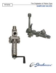
Air UPA<br />
Air Cooled Aftercoolers<br />
The smallest size cooler in a wide family of<br />
choices. Copper tube construction offering a<br />
high efficiency, high performing compressed air<br />
cooler in compact package. Baked enamel finish<br />
for all-weather service. Four models with flow<br />
capacities from 5-125 SCFM (.14-3.5 SCMM) and<br />
used on compressors from 5-25 HP (3.7-18.6 KW).<br />
Detachable legs allow the cooler to be oriented<br />
vertical or horizontal.<br />
Features<br />
n COPPER TUBE Construction<br />
n Full Line of Sizes and Features<br />
n Energy Efficient<br />
n High Performance<br />
n Low flows to 100 CFM (2.83 CMM)<br />
n Detachable Legs (shipped unattached)<br />
n Horizontal or Vertical Air Flow<br />
n Lightweight<br />
n Ratings Based on Comprehensive Testing<br />
n Attractive, Durable Baked Enamel Finish<br />
n Floor or Suspended Mounting<br />
Units shown with<br />
optional separator.<br />
Materials<br />
Rating<br />
n Cabinet – Steel with Baked Enamel Finish<br />
n Core – Aluminum Fins on Copper Tubes<br />
n Fan – Heavy Gauge Aluminum with Steel Hub<br />
n Motor – Open Vented<br />
n Fan Guard – Zinc Chromate Plated Steel<br />
n Maximum Operating Pressure 250 PSI (17 BAR)<br />
n Maximum Operating Temperature 350°F (177°C)<br />
Model Selection<br />
rotary Screw 200˚F (93˚C) 2-Stage Piston 250˚F (121˚C) 1-Stage Piston 300˚F (149˚C)<br />
<strong>Compressor</strong> Capacity* <strong>Compressor</strong> Capacity* <strong>Compressor</strong> Capacity*<br />
Model HP (KW) sCFM (CMM) HP (KW) sCFM (CMM) HP (KW) sCFM (CMM)<br />
UPA-20 5 (3.8) 35 (.99) — — — —<br />
UPA-35 7.5 (5.6) 43 (1.22) 5 (3.8) 35 (.99) 5 (3.8) 31 (.88)<br />
UPA-50 10 (7.5) 72 (2.04) 10 (7.5) 50 (1.42) 7.5 (5.6) 45 (1.27)<br />
UPA-100 15-25 (11.2-18.6) 125 (3.54) 15-20 (11.2-14.9) 100 (2.83) 15-20 (11.2-14.9) 100 (2.83)<br />
*For air flows above rated SCFM (CMM), use next larger size.<br />
Assumptions:<br />
n 80-125 PSIG (6-9 BAR) operating pressures 60 PSIG (4 BAR) minimum allowable.<br />
n Maximum pressure drop less than 3 PSIG (.2 BAR) at rated capacities.<br />
n A flexible metal hose should be properly installed between the compressor and aftercooler to validate warranty.
Dimensions (approximate envelope)<br />
UPA-20 & UPA-35<br />
UPA-50 & UPA-100<br />
UPA<br />
Horizontal Air Flow<br />
Horizontal Air Flow<br />
Inlet<br />
AIR<br />
FLOW<br />
AIR<br />
FLOW<br />
Height<br />
Height<br />
Outlet<br />
Outlet<br />
Inlet<br />
Width<br />
Depth<br />
Width<br />
Depth<br />
Vertical Air Flow<br />
Vertical Air Flow<br />
AIR<br />
FLOW<br />
Outlet<br />
AIR FLOW<br />
Inlet<br />
Outlet<br />
Height<br />
Height<br />
Width<br />
Depth<br />
Width<br />
Depth<br />
porT RECOMMENDED<br />
HORIZONTAL AIR FLOW VERTICAL AIR FLOW CONNECTION OPTIONAL<br />
HEIGHT widTH depTH HEIGHT widTH DEPTH siZE SEPARATOR<br />
Model Inches mm Inches mm Inches mm Inches mm Inches mm Inches mm NPT Model Number<br />
UPA-20 21.89 556 20.38 518 9.58 243 15.88 403 20.38 518 13.29 338 .50 S-50M or AD<br />
UPA-35 21.89 556 20.38 518 9.58 243 15.88 403 20.38 518 13.29 338 .50 S-50M or AD<br />
UPA-50 42.18 1071 26.11 663 20.93 532 40.12 1019 26.11 663 23.01 584 1.00 S-100M or AD<br />
UPA-100 42.18 1071 26.11 663 20.93 532 40.12 1019 26.11 663 23.01 584 1.50 S-100M or AD<br />
Motor & Fan Data<br />
approx.<br />
Full<br />
shipping<br />
Fan motor load nema Thermal Weight<br />
Model CFM (CMM) HP (KW) Voltage Phase Amps Hz rpm Frame Overload Lbs (Kg)<br />
UPA-20 615 (17.40) 1/12 (.06) 115/230 1 60/50 1550/1300 Custom Yes 25 (11)<br />
UPA-35 615 (17.40) 1/12 (.06) 115/230 1 2.4/1.2 60/50 1550/1300 Custom Yes 27 (12)<br />
UPA-50 945 (26.76) 1/12 (.06) 115/230 1 2.7/1.4 60/50 1550/1300 Custom Yes 61 (28)<br />
UPA-100 945 (26.76) 1/12 (.06) 115/230 1 60/50 1550/1300 Custom Yes 67 (30)
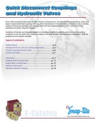
Air AA<br />
Air Cooled Aftercoolers<br />
Fits the requirements for medium performing ranges. Copper<br />
tube construction offering a high efficiency, high performing<br />
compressed air cooler in an attractive galvanized steel cabinet.<br />
The AA Series works in numerous common compressor<br />
applications. Six models with flow capacities from 16-480<br />
SCFM (.45-13.6 SCMM) and used on compressors from 5-60<br />
HP (3.7-44.7 KW). The free standing cooler can be ordered<br />
with a weather proof Junction box and wired for a single point<br />
electrical connection.<br />
Features<br />
n COPPER TUBE Construction<br />
n Full Line of Sizes and Features<br />
n Energy Efficient<br />
n High Performance<br />
n Medium Flows 80-300 CFM (2.27-8.50 CMM)<br />
n Horizontal Air Flow<br />
n Optional Weatherproof Junction Box<br />
n Floor or Suspended Mounting<br />
n Optional TEFC Motor(s)<br />
n Ratings Based on Comprehensive Testing<br />
n Wired for Single Point External Connection<br />
n Detachable Legs (shipped unattached)<br />
Materials<br />
n Cabinet – Galvanized Steel<br />
n Core – Aluminum Fins on Copper Tubes<br />
n Fan – Heavy Gauge Aluminum with Steel Hub<br />
n Motor – Open Vented<br />
n Fan Guard – Steel with Baked Enamel Finish<br />
Rating<br />
n Maximum Operating Pressure 250 PSI (17 BAR)<br />
n Maximum Operating Temperature 350°F (177°C)<br />
Model Selection<br />
rotary Screw 200˚F (93˚C) 2-Stage Piston 250˚F (121˚C) 1-Stage Piston 300˚F (149˚C)<br />
<strong>Compressor</strong> Capacity* <strong>Compressor</strong> Capacity* <strong>Compressor</strong> Capacity*<br />
Model HP (KW) sCFM (CMM) HP (KW) sCFM (CMM) HP (KW) sCFM (CMM)<br />
AA-50 5-10 (3.7-7.5) 59 (1.67) 5-10 (3.7-7.5) 50 (1.42) 5 (3.7) 42 (1.19)<br />
AA-80 15 (11.2) 94 (2.66) 15 (11.2) 80 (2.27) 10 (7.5) 71 (2.01)<br />
AA-120 20-25 (14.9-18.6) 142 (4.02) 20 (14.9) 120 (3.40) 15 (11.2) 102 (2.89)<br />
AA-150 30 (22.4) 172 (4.87) 25-30 (18.6-22.4) 150 (4.25) 20-25 (14.9-18.6) 130 (3.68)<br />
AA-240 40-50 (29.8-37.2) 285 (8.07) 35-45 (26.1-33.6) 240 (6.80) 30-40 (22.4-29.8) 204 (5.78)<br />
AA-300 60 (44.7) 345 (9.77) 50-60 (37.2-44.7) 300 (8.50) 45-50 (33.6-37.2) 257 (7.28)<br />
*For air flows above rated SCFM (CMM), use next larger size.<br />
Assumptions:<br />
n 80-125 PSIG (6-9 BAR) operating pressures 60 PSIG (4 BAR) minimum allowable.<br />
n Maximum pressure drop less than 3 PSIG (.2 BAR) at rated capacities.<br />
n A flexible metal hose should be properly installed between the compressor and aftercooler to validate warranty.
Dimensions (approximate envelope)<br />
AA<br />
Width<br />
Inlet<br />
Depth<br />
AIR<br />
FLOW<br />
12”<br />
(304.8)<br />
min. to<br />
wall<br />
Height<br />
Outlet<br />
porT<br />
reCOMMENDED<br />
CONNECTion<br />
opTIONAL<br />
HEIGHT widTH depTH siZe separaTOR<br />
Model inches mm inches mm inches mm npT model Number<br />
AA-50 50.50 1283 30.50 775 14.75 375 1.00 S-100M or AD<br />
AA-80 50.50 1283 30.50 775 14.75 375 1.50 S-100M or AD<br />
AA-120 50.50 1283 43.50 1105 14.75 375 1.50 S-200M<br />
AA-150 50.50 1283 43.50 1105 14.75 375 1.50 S-200M<br />
AA-240 53.50 1359 47.63 1210 14.75 375 2.00 S-300M<br />
AA-300 59.50 1511 51.68 1313 14.75 375 2.00 S-300M<br />
Motor & Fan Data<br />
Standard optional optional<br />
approx.<br />
Motor (ODP) motor (TEFC) motor (TEFC)*<br />
Shipping<br />
Air Motor<br />
Fan motor Full Load Full Load Full Load Weight PSI CFM<br />
Model CFM (CMM) HP (KW) Voltage Amps/Motor Voltage Amps/Motor Voltage Amps/Motor Lbs. (Kg) (BAR) (CMM)<br />
AA-50 1375 (38.94) 1/4 (0.19) 7.2 5/2.6-2.5 1.4-1.3/.65 110 (50) 50 (3.45) 13 (0.37)<br />
AA-80 1375 (38.94) 1/4 (0.19) 7.2 5/2.6-2.5 1.4-1.3/.65 120 (54) 50 (3.45) 13 (0.37)<br />
AA-120 2450 (69.38) 1/4 (0.19)<br />
7.2 115/208 5/2.6-2.5 208-230/ 1.4-1.3/.65 140 (64) 50 (3.45) 13 (0.37)<br />
115/1/60<br />
AA-150 2350 (66.54) 1/4 (0.19) 7.2 230/1/60 5/2.6-2.5 460/3/60 1.4-1.3/.65 145 (66) 50 (3.45) 13 (0.37)<br />
AA-240 4600 (130.26) 1/4 (0.19) 7.2 5/2.6-2.5 1.4-1.3/.65 200 (91) 50 (3.45) 13 (0.37)<br />
AA-300 4700 (133.09) 1/4 2 (0.19) 7.2 5/2.6-2.5 1.4-1.3/.65 300 (136) 50 (3.45) 13 (0.37)<br />
Standard Motor(s) = 1600 RPM, Custom Frame, Equipped with Thermal Overload. Optional Motor(s) = 1725 RPM, Nema 48 Frame, No Thermal Overload. Published electrical ratings are approximate,<br />
and may vary because of motor brand. Actual ratings are on motor nameplate. *3 phase motors available in 50Hz. Reduce performance by 10%. (1) Air inlet to motor must be regulated to this<br />
pressure. (2) CFM (Free Air) consumption of the air motor. Lubrication = one drop of oil for every 50-75 CFM (1.42-2.04 CMM) of air going through the motor. Use detergent SAE #10 oil. Filter, regulator<br />
and lubricators for the air motors are required, but not included.
;<br />
Air Belt Guard<br />
Air Cooled Aftercoolers<br />
No fan motor required via mounting to<br />
compressor belt guard. These coolers, built<br />
from either round cooper tube & fin or bar<br />
& plate brazed aluminum construction,<br />
allow the use of free air flow from the<br />
belt guard on reciprocating compressors.<br />
Compact and light weight, the Belt Guard<br />
Series is offered in seven models with<br />
capacities from 20-100 SCFM (.57-2.8 KW).<br />
Features M Models<br />
n COPPER TUBE Construction<br />
n Utilizes Air Flow from Belt Guard on Recip <strong>Compressor</strong><br />
n Easy to Install<br />
n Rugged Construction<br />
n Solid Performance<br />
n Bolt directly on the existing belt guard (some additional support<br />
may be required)<br />
n All steel manifolds with sturdy copper tubes and aluminum fins<br />
n Unique turbulator inside each cooling tube assures maximum<br />
performance in a compact size<br />
Features BGA Models<br />
n brazed aluminum Construction<br />
n Brazed Bar and Plate Aluminum Core<br />
n Energy Efficient<br />
n High Performance<br />
n High Technology Compact Design<br />
n Rugged Heavy Duty Construction<br />
n Excellent for Heat Recovery<br />
Materials<br />
Rating<br />
Materials<br />
Rating<br />
n Tubes – Copper<br />
n Fins – Aluminum<br />
n Turbulators – Steel<br />
n Manifolds – Steel<br />
n Maximum Operating<br />
Pressure 300 PSI (21 BAR)<br />
n Maximum Operating<br />
Temperature 350°F (177°C)<br />
n Core – Brazed Aluminum<br />
Bar & Plate<br />
n Maximum Operating<br />
Pressure 250 PSI (17 BAR)<br />
n Maximum Operating<br />
Temperature 350°F (177°C)<br />
Model Selection<br />
maximum Maximum<br />
Model sCFM* CMM<br />
M-15-76946 20 .57<br />
M-20-76785 35 .99<br />
M-25-76878 75 2.12<br />
M-30-76941 100 2.83<br />
maximum Maximum<br />
Model SCFM* CMM Model Rating Approach Temperature<br />
BGA-35-2/1 35 .99 5˚F for 18 SCFM 15˚F for 35 SCFM 3˚C for .51 CMM 8˚C for .99 CMM<br />
BGA-60-2/1 60 1.70 10˚F for 35 SCFM 25˚F for 60 SCFM 6˚C for .99 CMM 14˚C for 1.70 CMM<br />
BGA-100-2/1 100 2.83 13˚F for 70 SCFM 25˚F for 100 SCFM 7˚C for 1.98 CMM 14˚C for 2.83 CMM<br />
*Ratings are based on a 250°F (121°C) inlet temperature, 100 PSIG (7 BAR), and 500 FPM (152.4 MPM) air face velocity across the ambient side of the aftercooler.<br />
Maximum pressure drop is 3 PSI (.21 BAR) or less—all models. 25°F (14°C) approach temperature, unless stated otherwise.
Dimensions (approximate envelope)<br />
Belt Guard M15-30<br />
Copper Tube<br />
Inlet<br />
Depth<br />
Belt Guard<br />
Inlet<br />
Depth<br />
Height<br />
Height<br />
Outlet<br />
Width<br />
Outlet<br />
Width<br />
Belt Guard BGA35-100<br />
Brazed Aluminum<br />
Inlet<br />
Depth<br />
Height<br />
Width<br />
Outlet<br />
porT<br />
CONNECTION<br />
HEIGHT widTH depTH siZE<br />
Model inches mm inches mm inches mm npT<br />
M-15-76946 13.24 336 19.72 501 1.50 38 1.00<br />
M-20-76785 17.24 438 19.72 501 1.50 38 1.00<br />
M-25-76878 23.24 590 25.72 653 1.50 38 1.00<br />
M-30-76941 29.18 741 24.72 628 1.50 38 1.25<br />
BGA-35-2/1 6.81 173 17.68 449 1.77 45 1.00<br />
BGA-60-2/1 8.03 204 17.68 449 1.77 45 1.00<br />
BGA-100-2/1 10.43 265 19.65 499 1.77 45 1.00
Air AHP/AHPH<br />
Air Cooled Aftercoolers<br />
Our highest performing aftercooler, the AHP and AHPH are built from<br />
high-performance plate & bar aluminum construction. Energy efficient,<br />
durable and flexible mounting in horizontal or vertical configurations.<br />
The finish is a rugged black powder coating. Nine models with<br />
flow capacities from 125-4800 SCFM (3.5-135.9 SCMM) and used<br />
on compressors from 60-700 HP (44.7-522 KW). Fan options include<br />
electrical TEFC and air motor drive. The legs ship detached to<br />
allow the cooler to be installed in numerous configurations.<br />
Features<br />
n brazed aluminum Construction<br />
n Full Line of Sizes and Features<br />
n Brazed Bar and Plate Aluminum Core<br />
n Energy Efficient<br />
n Vertical (AHP) or Horizontal (AHPH) Air Flow<br />
n High Performance<br />
Materials<br />
n Cabinet – Steel with Baked Enamel Finish<br />
n Core – Brazed Aluminum Bar and Plate<br />
n Fan – Aluminum Hub, Polypropylene Blades<br />
n Shroud – Painted Steel<br />
n Motor – TEFC/optional Air<br />
n Fan Guard – Steel with Baked Enamel Finish<br />
n High Technology Compact Design<br />
n High Flows 400-3500 CFM (11.33-99.11 CMM)<br />
n Optional Air Motor<br />
n Rugged Heavy Duty Construction<br />
n Excellent for Heat Recovery<br />
n Detachable Legs on AHP (shipped unattached)<br />
Fixed Mounting Feet on AHPH<br />
Rating<br />
n Maximum Operating Pressure 250 PSI (17 BAR)<br />
n Maximum Operating Temperature 350°F (177°C)<br />
Model Selection<br />
rotary Screw 200˚F (93˚C) 2-Stage Piston 250˚F (121˚C) 1-Stage Piston 300˚F (149˚C)<br />
<strong>Compressor</strong> Capacity* <strong>Compressor</strong> Capacity* <strong>Compressor</strong> Capacity*<br />
Model HP (KW) sCFM (CMM) HP (KW) sCFM (CMM) HP (KW) sCFM (CMM)<br />
AHP(H)-400 75 (56.2) 430 (12.18) 75 (56.2) 400 (11.33) 60 (44.7) 340 (9.63)<br />
AHP(H)-725 100-150 (74.5-111.8) 760 (21.52) 100-125 (74.5-93.2) 725 (20.53) 75-100 (56.2-74.5) 605 (17.13)<br />
AHP(H)-950 175-200 (130.0-149.1) 1020 (28.88) 150-175 (111.8-130.0) 950 (26.90) 125-150 (93.2-111.8) 785 (22.23)<br />
AHP(H)-1200 250 (186.4) 1290 (36.53) 200 (149.1) 1200 (33.98) 175-200 (130.0-149.1) 980 (27.75)<br />
AHP(H)-1600 300 (223.7) 1720 (48.70) 250-300 (186.4-223.7) 1600 (45.31) 250 (186.4) 1290 (36.53)<br />
AHP(H)-2000 400 (298.2) 2140 (60.60) 350-400 (261.0-298.2) 2000 (56.63) 300 (223.7) 1595 (45.17)<br />
AHP(H)-2500 450-500 (335.6-372.9) 2680 (75.89) 450-500 (335.6-372.9) 2500 (70.79) 350 (261.0) 1980 (56.07)<br />
AHP-3000 600-650 (447.4-484.7) 3200 (90.61) 550-600 (410.1-447.4) 3000 (84.95) 400-450 (298.2-335.6) 2360 (66.83)<br />
AHP-3500 700-750 (522.0-559.3) 3760 (106.47) 700 (522.0) 3500 (99.11) 500-550 (372.9-410.1) 2760 (78.15)<br />
*For air flows above rated SCFM (CMM), use next larger size.<br />
Assumptions:<br />
n 80-125 PSIG (6-9 BAR) operating pressures 60 PSIG (4 BAR) minimum allowable.<br />
n Maximum pressure drop less than 3 PSIG (.2 BAR) at rated capacities.<br />
n 15˚F (8˚C) approach temperature<br />
n A flexible metal hose should be properly installed between the compressor and aftercooler to validate warranty.
Dimensions (approximate envelope)<br />
AHP<br />
Connection Port<br />
2 places<br />
AIR<br />
FLOW<br />
Connection Port<br />
2 places<br />
AHPH<br />
Connection Port<br />
2 places<br />
AHP / AHPH<br />
Height<br />
Inlet<br />
Height<br />
AIR<br />
FLOW<br />
Outlet<br />
Connection<br />
Port<br />
2 places<br />
Width<br />
Depth<br />
Width (over brackets)<br />
Depth<br />
porT RECOMMENDED<br />
AHP AHPH CONNECTION OPTIONAL<br />
HEIGHT widTH depTH HEIGHT widTH DEPTH siZE SEPARATOR<br />
Model Inches mm Inches mm Inches mm Inches mm Inches mm Inches mm NPT Model Number<br />
AHP(H)-400 34.20 869 26.22 666 17.96 456 19.95 507 22.45 570 17.48 444 2.00 S-600M<br />
AHP(H)-725 34.20 869 34.10 866 22.37 568 24.37 619 30.17 766 20.86 530 2.00 S-600M<br />
AHP(H)-950 36.01 915 40.78 1036 26.78 680 28.82 723 35.89 912 22.69 576 3.00 S-1700M<br />
AHP(H)-1200 36.01 915 44.73 1136 26.78 680 28.82 732 40.31 1024 24.07 611 3.00 S-1700M<br />
AHP(H)-1600 36.01 915 44.73 1136 34.89 886 36.89 937 40.31 1024 25.45 646 3.00 S-2600M<br />
AHP(H)-2000 36.01 915 54.58 1386 37.88 962 39.53 1004 48.29 1227 26.77 680 4.00 S-2600M<br />
AHP-2500 36.01 915 52.61 1336 43.70 1110 — — — — — — 4.00 S-2600M<br />
AHP-3000 36.01 915 54.58 1386 52.52 1334 — — — — — — 4.00 S-2600M<br />
AHP-3500 36.01 915 54.58 1386 56.30 1430 — — — — — — 4.00 S-2600M<br />
Motor & Fan Data<br />
approx.<br />
Full shipping Sound<br />
AIR MOTOR<br />
Fan motor load nema Thermal Weight dB(A) PSI 1 CFM 2<br />
Model CFM (CMM) HP (KW) Voltage Phase Amps Hz RPM Frame Overload Lbs. (Kg) at 3 ft (BAR) (CMM)<br />
AHP(H)-400<br />
AHP(H)-725<br />
AHP(H)-950<br />
AHP(H)-1200<br />
2200 (62.3) 1.0 (.75) 115/208-230 1 6.0 60 3450 56C No 120 (54) 97 60 (4.14) 50 (1.42)<br />
1825/2200 (51.68/62.3) 1.0 (.75) 208-230/460 3 3.6/3.2 50/60 2850/3450 56C No 120 (54) 97 60 (4.14) 50 (1.42)<br />
3600 (101.94) 1.5 (1.12) 115/208-230 1 8.5 60 3450 56C No 170 (77) 100 85 (5.86) 65 (1.84)<br />
3025/3600 (85.66/101.94) 1.5 (1.12) 208-230/460 3 4.8/4.2 50/60 2850/3450 56C No 170 (77) 100 85 (5.86) 65 (1.84)<br />
4700 (133.09) 1.5 (1.12) 115/208-230 1 8.6 60* 1740 145TC No 330 (150) 92 60 (4.14) 55 (1.56)<br />
4700 (133.09) 1.5 (1.12) 208-230/460 3 4.6 60* 1740 145TC No 330 (150) 92 60 (4.14) 55 (1.56)<br />
7000 (198.22) 5.0 (3.73) 230 1 23.0 60* 1740 184TC No 450 (204) 94 70 (4.83) 100 (2.83)<br />
7000 (198.22) 3.0 (2.24) 208-230/460 3 8.8 60* 1740 182TC No 450 (204) 94 70 (4.83) 100 (2.83)<br />
AHP(H)-1600 9700 (274.67) 5.0 (3.73) 208-230/460 3 13.4 60* 1740 184TC No 515 (234) 96 100 (6.89) 180 (5.10)<br />
AHP(H)-2000 11000 (311.49) 7.5 (5.59) 230/460 3 19.6 60* 1740 213TC No 600 (272) 98 90 (6.21) 230 (6.51)<br />
AHP-2500 14000 (396.44) 7.5 (5.59) 230/460 3 24.8 60* 1740 213TC No 625 (284) 98 90 (6.21) 230 (6.51)<br />
AHP-3000 17500 (495.54) 10.0 (7.46) 230/460 3 24.8 60* 1740 215TC No 645 (293) 102 100 (6.89) 275 (7.79)<br />
AHP-3500 17500 (495.54) 10.0 (7.46) 230/460 3 24.8 60* 1740 215TC No 750 (340) 102 100 (6.89) 275 (7.79)<br />
All motors shown are TEFC. Other motor options available upon request. Published electrical ratings are approximate, and may vary because of motor brand. Actual ratings are on motor nameplate.<br />
Fan motors must not be cycled. Outdoor applications must be protected from direct weather. If ductwork or additional static resistance is added to the cooler airstream, an auxiliary air mover<br />
may be required.<br />
*3 phase motors available in 50Hz. Reduce performance by 10%.<br />
1<br />
Air inlet to the air motor must be regulated to this pressure.<br />
2<br />
CFM (Free Air) consumption of the air motor. Lubrication = One drop of oil for every 50-75 CFM (1.42-2.12 CMM) of air going through the motor. Use detergent SAE #10 oil. Filter, regulator and lubricators<br />
for the air motors are required, but not included.
Industrial AOL<br />
Air Cooled Oil Cooler<br />
Apply this cooler for rotary screw, compressor lube or<br />
gear box oils. The AOL Series utilizes forced ambient air<br />
to cool compressor lube oil and is an excellent choice<br />
for demanding oil cooler requirements or for converting<br />
medium to large volume water cooled compressors to air<br />
cooled. Built from rugged brazed aluminum bar & plate<br />
and designed with detachable legs for ease of mounting<br />
in alternate locations. Nine models available with oil flow<br />
capacities from 15-120 GPM (57-454 LPM) and used on<br />
compressors from 35-400 HP (26.1-298.3 KW).<br />
Features<br />
n Large oil flow<br />
n High performance<br />
n Industrial duty<br />
n Brazed aluminum bar and plate core<br />
n Compact all aluminum core assembly<br />
n Ideal for converting water cooled equipment to air cooled<br />
n Eliminates high water and sewer costs<br />
n Eliminates corrosion problems associated with water<br />
cooled units<br />
n Vertical air flow works well for heat recovery<br />
n State-of-the-art heat transfer technology<br />
n Hydraulic motors available<br />
n Optional SAE ports<br />
n Marine corrosion control coatings available<br />
n High performance air side fin design<br />
n Detachable legs<br />
n Low Noise option available<br />
n Optional IEC or Nema 50 hz motor<br />
Materials Rating Fluid Compatibility<br />
n Legs – Steel with Baked Enamel Finish<br />
n Standard Core – Brazed Aluminum Plate & Bar<br />
n Tanks – 5052 Aluminum<br />
n Nose Bar & Little Bar – 3003-H Aluminum<br />
n Air Fin, Plate, Turbulator & End Plate –<br />
3003-O Aluminum<br />
n Fan – Aluminum Hub, Plastic Blades<br />
n Motor – TEFC, IEC & Hydraulic<br />
n Maximum Operating Pressure<br />
250 PSI (17 BAR)<br />
n Maximum Operating Temperature<br />
300°F (150°C)<br />
n Petroleum/mineral oils<br />
n Oil/water emulsion<br />
n Water/ethylene glycol<br />
Model Selection<br />
<strong>Compressor</strong><br />
Flow Range*<br />
Model HP (KW) GPM (LPM)<br />
AOL-400 35-45 (26.10-33.56) 15-20 (57-76)<br />
AOL-725 45-85 (33.56-63.38) 25-40 (95-151)<br />
AOL-950 85-135 (63.38-100.67) 40-50 (151-189)<br />
AOL-1200 135-165 (100.67-123.04) 50-60 (189-227)<br />
*Oil pressure drop less than 15 PSI (1.03 BAR) for specified flow ranges.<br />
Assumptions:<br />
n Heat Rejection = .85 x <strong>Compressor</strong> HP<br />
n 100°F (56°C ) ETD (Oil In - Ambient Air)<br />
n 150 SSU Average Viscosity Oil<br />
<strong>Compressor</strong> Flow Range*<br />
Model HP (KW) GPM (LPM)<br />
AOL-1600 165-215 (123.04-160.33) 50-65 (189-246)<br />
AOL-2000 215-285 (160-33-212.52) 70-90 (265-341)<br />
AOL-2500 295-335 (219.98-249.81) 90-100 (341-379)<br />
AOL-3000 345-400 (257.27-298.28) 100-120 (379-454)<br />
AOL-3500 400-450 (298.28-335.56) 120-140 (454-530)
Dimensions (approximate envelope)<br />
AOL<br />
Width<br />
AIR<br />
FLOW<br />
Inlet / Outlet<br />
(Interchangeable)<br />
Depth<br />
Height<br />
Inlet / Outlet<br />
(Interchangeable)<br />
porT approximate<br />
CONNECTION<br />
Shipping<br />
HEIGHT depTH widTH siZE Weight<br />
Model inches mm inches mm inches mm npT lbs Kg<br />
AOL-400 34.20 869 17.96 456 26.23 666 2.00 148 67<br />
AOL-725 34.20 869 22.37 568 34.11 866 2.00 170 77<br />
AOL-950 36.01 915 26.78 681 40.79 1036 2.00 300 136<br />
AOL-1200 36.01 915 26.78 681 44.74 1136 2.00 430 195<br />
AOL-1600 36.01 915 34.89 886 44.74 1136 2.50 515 234<br />
AOL-2000 36.01 915 37.88 962 54.59 1387 2.50 582 264<br />
AOL-2500 36.01 915 43.70 1110 52.62 1337 3.00 655 297<br />
AOL-3000 36.01 915 52.52 1334 54.59 1387 3.00 825 374<br />
AOL-3500 36.01 915 56.30 1430 54.59 1387 3.00 860 390<br />
Motor & Fan Data (1)<br />
(60 Hz Nema Frame)<br />
Fan motor Full Load N nema Thermal Sound<br />
Model CFM (CMM) HP (KW) Voltage Phase Amps 230V Hz RPM Frame Overload dB(A) at 3 ft.<br />
AOL-400<br />
AOL-725<br />
AOL-950<br />
AOL-1200<br />
2200 (62.30) 1.0 (.75) 115/208-230 1 6.0 60 (2) 3450 56C No 97<br />
1825/2200 (51.68/62.30) 1.0 (.75) 208-230/460 (3) 3 3.6/3.2 50/60 2850/3450 56C No 97<br />
3600 (101.94) 1.5 (1.12) 115/208-230 1 8.5 60 (2) 3450 56C No 100<br />
3000/3600 (84.95/102.94) 1.5 (1.12) 208-230/460 (4) 3 4.8/4.2 50/60 2850/3450 56C No 100<br />
4700 (133.09) 1.5 (1.12) 115/208-230 1 8.6 60 (2) 1740 145TC No 92<br />
4700 (133.09) 1.5 (1.12) 208-230/460 3 4.6 60 (2) 1740 145TC No 92<br />
7000 (198.22) 5.0 (3.73) 230 1 23.00 60 (2) 1740 184TC No 94<br />
7000 (198.22) 3.0 (2.24) 208-230/460 3 8.8 60 (2) 1740 182TC No 96<br />
AOL-1600 9700 (223.70) 5.0 (3.73) 208-230/460 3 13.4 60 (2) 1740 184TC No 98<br />
AOL-2000 11000 (311.49) 7.5 (5.59) 230/460 3 19.6 60 (2) 1740 213TC No 98<br />
AOL-2500 14000 (396.44) 7.5 (5.59) 230/460 3 19.6 60 (2) 1740 213TC No 98<br />
AOL-3000 17500 (495.54) 10.0 (7.46) 230/460 3 24.8 60 (2) 1740 215TC No 102<br />
AOL-3500 17500 (495.54) 10.0 (7.46) 230/460 3 24.8 60 (2) 1740 215TC No 102<br />
(1)<br />
Published electrical ratings are approximate, and may vary because of motor brand. Actual ratings are on motor nameplate.<br />
(2)<br />
May also be operated at 50 hz. Consult factory for details.<br />
(3)<br />
50 Hz voltage: 190-200-208-220/380-400-415-440<br />
(4)<br />
50 Hz voltage: 190-208/380-415<br />
All motors shown are TEFC—Other motor options available upon request.
Air ACOC / ACOCH<br />
Air Cooled combination (oil cooler / aftercooler)<br />
Air<br />
Aftercooler<br />
Oil<br />
Cooler<br />
The best of both worlds in one compact, side by side,<br />
combination package. Cools rotary screw compressor oil<br />
and compressed air in a single combined core. Ideal for<br />
conversions, stringent space requirements and remote location<br />
mounting. Built from rugged brazed aluminum bar & plate<br />
and designed with detachable legs for ease of mounting, and<br />
now available in vertical orientation. Fifteen models with flow<br />
capacities from 175-1800 SCFM (4.96-50.97 SCMM) and used<br />
on compressors from 15-360 HP (11.2-268.5 KW).<br />
Features<br />
Air<br />
Aftercooler<br />
Oil<br />
Cooler<br />
n brazed aluminum Construction<br />
n Combination Welded Cores – Air & Oil Core<br />
n Brazed Aluminum Core/Bar and Plate<br />
n Excellent for Field Conversions<br />
n Vertical (ACOC) or Horizontal (ACOCH) Air Flow<br />
n Compact Design<br />
n Light Weight<br />
n State-of-the-art heat transfer technology<br />
Materials<br />
n Legs – Steel with Baked Enamel Finish<br />
n Shroud – Steel<br />
n Core – Brazed Aluminum Bar and Plate<br />
n Fan – Aluminum Hub, Plastic Blades<br />
n Motor – TEFC<br />
n Compact, high performance all aluminum<br />
core assembly<br />
n Designed specifically for rotary screw compressors<br />
n Ideal for converting water cooled units to air cooled<br />
n Eliminates high water and sewer costs<br />
n Eliminates corrosion problems associated with water cooled units<br />
n Vertical air flow works well for heat recovery<br />
n Detachable Legs on ACOC (shipped unattached)/Fixed Mounting Feet on ACOCH<br />
Rating<br />
n Maximum Operating Pressure 250 PSI (17 BAR)<br />
n Maximum Operating Temperature 350°F (177°C)<br />
Model Selection<br />
<strong>Compressor</strong> maximum<br />
Model HP (KW) sCFM (CMM)<br />
ACOC(H)-400 15-35 (11.90-26.10) 175 (4.96)<br />
ACOC(H)-725 40-55 (29.83-41.01) 275 (7.79)<br />
ACOC(H)-950 60-85 (44.74-63.38) 425 (12.03)<br />
ACOC(H)-1200 90-120 (67.11-89.48) 600 (16.99)<br />
ACOC(H)-1600 125-155 (93.21-115.58) 775 (21.95)<br />
ACOC(H)-2000 160-225 (119.31-167.78) 1125 (31.86)<br />
ACOC-2500 230-275 (171.51-205.07) 1375 (38.94)<br />
ACOC-3000 280-325 (208.08-242.35) 1625 (46.01)<br />
ACOC-3500 330-360 (246.08-268.45) 1800 (50.97)<br />
Assumptions:<br />
n 100 PSI (7 BAR) air<br />
n Oil flow is .45 GPM/HP (1.4 L/KW)<br />
Bottom view of cooler to illustrate piping<br />
To Plant<br />
n 15°F (8°C ) ETD approach temperature<br />
Relief Valve<br />
Receiver<br />
n Oil pressure drop 15 PSI (1.03 BAR) or less<br />
Dryer<br />
Coalescing Filter<br />
Separator/<br />
Trap/Drain<br />
Heat Exchanger<br />
Thermal<br />
By-Pass Valve<br />
n Oil heat transfer based on 100°F (56°C ) ETD (ETD = Entering Temperature Difference) ( ETD = Oil in Temperature - Ambient Air Temperature)<br />
n Air aftercooler pressure drop 3 PSI (.21 BAR) or less.<br />
n ETD Temperature Correction Factor: HP chart = HP compressor x 100°F (56°C )<br />
desired ETD<br />
Air to Air Reheater<br />
Air/Oil Separator<br />
Flexible Connector<br />
<strong>Compressor</strong>
Dimensions (approximate envelope)<br />
ACOC<br />
Air<br />
Inlet<br />
Oil<br />
Inlet<br />
Width<br />
Air<br />
Outlet<br />
Depth<br />
Oil<br />
Outlet<br />
AIR<br />
FLOW<br />
Height<br />
ACOCH<br />
Air<br />
Inlet<br />
Oil<br />
Inlet<br />
Height<br />
Air<br />
Outlet<br />
Oil<br />
Outlet<br />
AIR<br />
FLOW<br />
acoc / ACOCH<br />
Width<br />
Depth<br />
air PORT<br />
OIL PORT<br />
ACOC ACOCH CONNECTION CONNECTION<br />
HEIGHT widTH depTH HEIGHT widTH depTH siZe siZE<br />
Model Inches mm Inches mm Inches mm Inches mm Inches mm Inches mm npT npT<br />
ACOC(H)-400 34.20 869 26.22 666 17.96 456 19.88 505 22.45 570 18.01 457 1.50 1.00<br />
ACOC(H)-725 34.20 869 34.10 866 22.37 568 24.37 619 30.56 776 20.86 530 1.50 1.00<br />
ACOC(H)-950 36.01 915 40.78 1036 26.78 680 28.82 732 37.24 946 23.62 600 2.00 1.25<br />
ACOC(H)-1200 36.01 915 44.73 1136 26.78 680 28.82 732 41.19 1046 25.51 648 2.00 1.25<br />
ACOC(H)-1600 36.01 915 44.73 1136 34.89 886 36.89 937 41.19 1046 27.51 699 2.50 1.50<br />
ACOC(H)-2000 36.01 915 54.58 1386 37.88 962 39.53 1004 39.88 1013 28.51 724 2.50 1.50<br />
ACOC-2500 36.01 915 52.61 1336 43.70 1110 — — — — — — 3.00 2.00<br />
ACOC-3000 36.01 915 54.58 1386 52.52 1334 — — — — — — 3.00 2.00<br />
ACOC-3500 36.01 915 54.58 1386 56.30 1430 — — — — — — 4.00 2.50<br />
Motor & Fan Data<br />
approx.<br />
shipping<br />
Fan motor Thermal Weight<br />
Model CFM (CMM) HP (KW) Voltage Phase Amps 230V Hz RPM Frame Overload Lbs (Kg)<br />
ACOC(H)-400<br />
ACOC(H)-725<br />
ACOC(H)-950<br />
ACOC(H)-1200<br />
2200 (62.30) 1.0 (.75) 115/208-230 1 6.0 60 (1) 3450 56C No 136 (62)<br />
1825/2200 (51.68/62.30) 1.0 (.75) 208-230/460 (2) 3 3.6/3.2 50/60 2850/3450 56C No 136 (62)<br />
3600 (101.94) 1.5 (1.12) 115/208-230 1 8.5 60 (1) 3450 56C No 155 (70)<br />
3025/3600 (85.66/101.94) 1.5 (1.12) 208-230/460 (3) 3 4.8/4.2 50/60 2850/3450 56C No 155 (70)<br />
4700 (133.09) 1.5 (1.12) 115/208-230 1 8.6 60 (1) 1740 145TC No 280 (127)<br />
4700 (133.09) 1.5 (1.12) 208-230/460 3 4.6 60 (1) 1740 145TC No 280 (127)<br />
7000 (198.22) 5.0 (3.73) 230 1 23.0 60 (1) 1740 184TC No 410 (186)<br />
7000 (198.22) 3.0 (2.24) 208-230/460 3 8.8 60 (1) 1740 182TC No 410 (186)<br />
ACOC(H)-1600 9700 (223.70) 5.0 (3.73) 208-230/460 3 13.4 60 (1) 1740 184TC No 495 (225)<br />
ACOC(H)-2000 11000 (311.49) 7.5 (5.59) 230/460 3 19.6 60 (1) 1740 213TC No 530 (240)<br />
ACOC-2500 14000 (396.44) 7.5 (5.59) 230/460 3 19.6 60 (1) 1740 213TC No 540 (245)<br />
ACOC-3000 17500 (495.54) 10.0 (7.46) 230/460 3 24.8 60 (1) 1740 215TC No 780 (354)<br />
ACOC-3500 17500 (495.54) 10.0 (7.46) 230/460 3 24.8 60 (1) 1740 215TC No 820 (372)<br />
All motors shown are TEFC—Other motor options available upon request.<br />
Published electrical ratings are approximate and may vary because of motor brand. Actual ratings are on motor nameplate.<br />
(1)<br />
May also be operated at 50 Hz. Consult factory for details.<br />
(2)<br />
50 Hz voltage: 190-200-208-220/380-400-415-440<br />
(3)<br />
50 Hz voltage: 190-208/380-415
Air AB<br />
water Cooled Aftercoolers<br />
High performance aftercooler utilizing supplied water to cool<br />
compressed gas or air from piston compressors. Constructed<br />
using round copper tubes, which allow the air side tube bundle<br />
to be easily cleaned and maintained. Brass hub and shell<br />
construction protect against galvanic corrosion. Great for<br />
piston or screw style compressors. Ten models with flow<br />
capacities from 40-3170 SCFM (1.1-89.8 SCMM).<br />
Features<br />
n copper tube Construction<br />
n Compressed Air and Gas Aftercoolers<br />
n For Water to Air Cooler<br />
Materials<br />
n Tubes – Copper<br />
n Shell – Brass<br />
n End Hubs – Brass<br />
n End Bonnets – Cast Iron<br />
n Baffles – Brass<br />
n Mounting Brackets (optional) – Steel<br />
n Gaskets – Nitrile Rubber<br />
n Nameplate – Aluminum Foil<br />
n All Brass Hubs and Shell Assemblies: Reduce or<br />
Eliminate Galvanic and Other Types of Corrosion<br />
n Copper Nickel Tubes Available for Sea Water Service<br />
Rating<br />
n Maximum Operating Pressure<br />
Tubes 250 PSI (17 BAR)<br />
Shell 250 PSI (17 BAR)<br />
n Maximum Operating Temperature 350°F (177°C)<br />
Model Selection<br />
2-stage recip 250˚F (121˚C) inlet air rotary screw 200˚F (93˚C)<br />
sCFM (CMM) P, PSI (BAR), at sCFM (CMM) P, PSI (BAR), at<br />
Model Capacity* in Tubes Rated Capacity Capacity* in Tubes Rated Capacity<br />
AB-403-A4-0 40 (1.13) 0.1 (.01) 58 (1.64) 0.1 (.01)<br />
AB-404-A4-0 80 (2.27) 0.3 (.02) 110 (3.11) 0.6 (.04)<br />
AB-405-B4-0 150 (4.25) 1.2 (.08) 205 (5.80) 2.0 (.14)<br />
AB-705-B4-0 310 (8.78) 1.0 (.07) 439 (12.43) 1.6 (.11)<br />
AB-1006-B6-0 440 (12.46) 0.3 (.02) 654 (18.52) 0.5 (.03)<br />
AB-1206-C6-0 640 (18.12) 0.3 (.02) 955 (27.04) 0.6 (.04)<br />
AB-1207-C6-0 1250 (35.40) 1.1 (.08) 1690 (47.86) 1.9 (.13)<br />
AB-1606-C6-0 1600 (45.31) 0.5 (.03) 2280 (64.56) 0.9 (.06)<br />
AB-1607-D6-0 2100 (59.47) 1.0 (.07) 3080 (87.22) 1.7 (.12)<br />
AB-1608-D6-0 2800 (79.29) 1.6 (.11) 3170 (89.76) 2.0 (.14)<br />
*Based on ambient air at 60°F (15°C), 14.7 PSIA, and 50% relative humidity. Compressed air cooled to within 15°F (8°C ) of inlet water<br />
temperature. Water flow rate 3 GPM per 100 SCFM (4 LPM per SCMM) air flow. For single stage compressor type, 300°F (149°C ) inlet,<br />
use 2-stage SCFM capacities with a 15% reduction.<br />
SELECTION EXAMPLE<br />
Specified<br />
Two stage compressor with a 340 SCFM<br />
(9.63 SCMM) air delivery at 100 PSIG (7 BAR)<br />
and a 250°F (121°C) discharge temperature.<br />
Maximum allowable pressure drop is 2 PSI<br />
(.14 BAR). Water flow rate to be determined.<br />
Solution<br />
STEP 1 From the 2-stage compressor<br />
column select model<br />
AB-1006-B6-0 with 440 SCFM<br />
capacity.<br />
STEP 2 To determine P: Read column to<br />
right of SCFM capacity selected.<br />
P = 0.3 PSI (.02 BAR)<br />
STEP 3<br />
Water flow rate required<br />
340 SCFM x .03 = 10.2 GPM<br />
(9.63 SCMM x 4 = 38.6 LPM)
Dimensions (approximate envelope)<br />
ab<br />
Length<br />
Height<br />
Mounting Brackets Optional<br />
Width<br />
PORT CONNECTION SIZE<br />
HEIGHT widTH lenGTH sHELL Tube weiGHT<br />
Model inches mm Inches mm Inches mm npT npT lbs Kg<br />
AB-403-A4-0 3.50 89 2.62 67 33.36 847 .50 1.50 13 6<br />
AB-404-A4-0 3.50 89 2.62 67 42.36 1076 .50 1.50 16 7<br />
AB-405-B4-0 3.50 89 2.62 67 51.36 1305 .50 1.50 18 9<br />
AB-705-B4-0 6.25 159 5.25 133 50.40 1280 1.00 2.50 40 18<br />
AB-1006-B6-0 7.38 187 6.75 171 59.60 1514 1.50 3.00 80 36<br />
AB-1206-C6-0 8.81 224 7.50 191 60.25 1530 2.00 3.00 130 59<br />
AB-1207-C6-0 8.81 224 7.50 191 69.25 1759 2.00 3.00 150 68<br />
AB-1606-C6-0 12.13 308 8.62 219 62.62 1591 3.00 5.00 259 117<br />
AB-1607-D6-0 12.13 308 8.62 219 71.62 1819 3.00 5.00 270 122<br />
AB-1608-D6-0 12.13 308 8.62 219 80.62 2048 3.00 5.00 315 143<br />
Piping Diagrams<br />
From<br />
<strong>Compressor</strong><br />
Thermal Transfer Aftercoolers can be mounted in either of the positions shown.<br />
Separators should be used as shown. Consult factory for separator recommendations.<br />
Cooling Water Out<br />
Separator<br />
From<br />
<strong>Compressor</strong><br />
Cooling Water Out<br />
ut<br />
From<br />
<strong>Compressor</strong><br />
Separator<br />
Cooling Water In<br />
To Receiver<br />
Cooling Water Out<br />
Cooling Water In<br />
Sep<br />
To Receiver<br />
Separator<br />
Cooling Water In<br />
To Receiver
Shell & Tube C & SSC<br />
water Cooled oil cooler/Aftercoolers<br />
Shell & Tube style air/oil coolers offer the widest variety of options for cooling<br />
compressor lube oil or air utilizing water. This model is an excellent choice where seawater or<br />
corrosive fluids are in contact with cooler internals. For new applications, interchange or ASME<br />
codes are required. Seventeen models with air flow capacities from 75-1500 SCFM (2.12-42.48<br />
SCMM) or oil flow from 7-105 GPM (27-397 LPM) and heat rejection from 14-281 HP (10.4-209.5 KW).<br />
Features<br />
n Copper/Steel or stainless steel<br />
Construction<br />
n API/BASCO Interchange<br />
n ASME Code Option<br />
n CRN Option (must be ASME)<br />
n Preferred for New Oil-Water Applications<br />
n Rugged Steel Construction<br />
n Low Cost<br />
n Type 316 Stainless Steel Construction Optional<br />
n Custom Designs Available<br />
n Competitively Priced<br />
n End Bonnets Removable for Servicing<br />
n Optional Material Construction on C-Series:<br />
Tubes, Tubesheets, End Bonnets<br />
n NPT, SAE O-Ring, SAE Flange, or BSPP<br />
Shell Side Connections Available<br />
n Mounting Feet Included (May be rotated<br />
in 90° increments)<br />
Materials C Models<br />
Materials SSC Models<br />
n Tubes – Copper<br />
n Headers – Steel<br />
n Shell – Steel<br />
n Shell Connections – Steel<br />
n Baff les – Brass<br />
n End Bonnets – Cast Iron<br />
n Mounting Brackets – Steel<br />
n Gaskets – Nitrile Rubber/<br />
Cellulose Fiber<br />
n Nameplate – Aluminum Foil<br />
n Tubes & Tubesheets –<br />
316 Stainless Steel<br />
n Shell & Shell Connections –<br />
316 L Stainless Steel<br />
n Baff les & End Bonnets –<br />
316 Stainless Steel<br />
n Mounting Brackets –<br />
Mild Steel<br />
n Gaskets – Nitrile Rubber/<br />
Cellulose Fiber<br />
n Nameplate – Aluminum Foil<br />
Ratings Standard<br />
n Maximum Shell Pressure 300 PSI (21 BAR)<br />
n Maximum Tube Side Pressure 150 PSI (10 BAR)<br />
n Maximum Temperature 300°F (150°C)<br />
Ratings ASME Code/CRN Option<br />
n Maximum Shell Pressure 300 PSI (21 BAR)<br />
n Maximum Tube Side Pressure 150 PSI (10 BAR)<br />
n ASME Code SSC-1700 200 PSI (14 BAR)<br />
n Maximum Temperature 300°F (150°C)<br />
Model Selection<br />
water cooled aftercoolers* C series water cooled Oil Coolers** C Series<br />
compressor Maximum Airflow Approach Aftercooler Approx. Oil Flow Heat Rejection Oil Cooler<br />
HP (KW) CFM (CMM) Temperature model GPM (LPM) HP (KW) model<br />
15 (11.19) 75 (2.12) 15°F (8.3°C) C-614-3-4-F 7 (26.50) 14 (10.44) C-614-1.3-4-F<br />
20 (14.91) 100 (2.83) 15°F (8.3°C) C-614-3-4-F 9 (34.07) 19 (14.17) C-624-3-4-F<br />
25 (18.64) 125 (3.54) 15°F (8.3°C) C-614-3-4-F 11 (41.64) 23 (17.15) C-624-3-4-F<br />
30 (22.37) 150 (4.25) 15°F (8.3°C) C-814-4-4-F 14 (53.00) 28 (20.88) C-624-3-4-F<br />
40 (29.83) 200 (5.66) 15°F (8.3°C) C-814-4-4-F 18 (68.14) 37 (27.59) C-824-4-4-F<br />
50 (37.28) 250 (7.08) 15°F (8.3°C) C-1024-5-6-F 23 (87.06) 47 (35.05) C-824-4-4-F<br />
60 (44.47) 300 (8.50) 15°F (8.3°C) C-1024-5-6-F 27 (102.21) 56 (41.76) C-1024-2-6-F<br />
75 (55.93) 375 (10.62) 15°F (8.3°C) C-1024-5-6-F 34 (128.70) 70 (52.20) C-1036-5-6-F<br />
100 (74.57) 500 (14.16) 15°F (8.3°C) C-1224-6-6-F 45 (170.34) 94 (70.10) C-1236-2.5-6-F<br />
125 (93.21) 625 (17.70) 15°F (8.3°C) C-1724-8.4-6-F 56 (211.98) 117 (87.25) C-1236-6-6-F<br />
150 (111.85) 750 (21.24) 15°F (8.3°C) C-1736-8.4-6-F 60 (227.12) 140 (104.40) C-1248-6-6-F<br />
200 (149.14) 1000 (28.32) 15°F (8.3°C) C-1736-8.4-6-F 70 (264.98) 187 (139.45) C-1748-8.4-6-F<br />
250 (186.42) 1250 (35.40) 15°F (8.3°C) C-1736-8.4-6-F 88 (333.12) 234 (174.49) C-1748-8.4-6-F<br />
300 (223.71) 1500 (42.48) 15°F (8.3°C) C-1736-8.4-6-F 105 (397.47) 281 (209.54) C-1760-8.4-6-F<br />
*Assumptions:<br />
n Operating Temperature =<br />
185°F (85°C)<br />
n Water Temperature = 85°F<br />
(29°C)<br />
n Water Flow = SCFM x .03<br />
(SCMM x 4)<br />
n Operating Pressure of 100 PSIG<br />
(6.89 BAR)<br />
**Assumptions: <br />
n Operating Temperature =<br />
185°F (85°C)<br />
n Water Temperature = 85°F<br />
(29°C) 5°F (3°C) rise through<br />
Aftercooler if in series<br />
n 2:1 Oil to Water Ratio<br />
n ISO-VG46 Oil or Equivalent
Dimensions (approximate envelope)<br />
SAE<br />
Flange<br />
Option<br />
C / SSC<br />
Height<br />
Length<br />
Width<br />
All models except<br />
C-1700 Series<br />
C-1700 Series<br />
HEIGHT<br />
TUBE PORT<br />
SHELL PORT CONNECTION SIZE<br />
NPT/BSPP<br />
SAE<br />
CONNECTION<br />
sae O-Ring Flange WIDTH LENGTH NPT/BSPP SAE siZe weiGHT<br />
Model Inches mm Inches mm Inches mm Inches mm Flange O-Ring NPT/BSPP Lbs Kg<br />
614 5.37 136 5.63 143 3.24 82 16.38 416 1.00 #16 1 5 /8-12 UNF-2B .75 17 8<br />
624 5.37 136 5.63 143 3.24 82 26.38 670 1.00 #16 1 5 /8-12 UNF-2B .75 24 11<br />
814 6.75 171 7.00 178 3.50 89 16.62 422 1.50 #24 1 7 /8-12 UN-2B .75 32 15<br />
824 6.75 171 7.00 178 3.50 89 26.62 676 1.50 #24 1 7 /8-12 UN-2B .75 41 19<br />
836 6.75 171 7.00 178 3.50 89 38.62 981 1.50 #24 1 7 /8-12 UN-2B .75 53 24<br />
1014 7.75 197 8.00 203 4.00 102 17.12 435 1.50 #24 1 7 /8-12 UN-2B 1.00 43 20<br />
1024 7.75 197 8.00 203 4.00 102 27.12 689 1.50 #24 1 7 /8-12 UN-2B 1.00 57 26<br />
1036 7.75 197 8.00 203 4.00 102 39.12 994 1.50 #24 1 7 /8-12 UN-2B 1.00 72 33<br />
1224 8.75 222 9.38 238 5.00 127 27.13 689 2.00 #32 2½-12 UN-2B 1.50 85 39<br />
1236 8.75 222 9.38 238 5.00 127 39.13 994 2.00 #32 2½-12 UN-2B 1.50 110 50<br />
1248 8.75 222 9.38 238 5.00 127 51.13 1299 2.00 #32 2½-12 UN-2B 1.50 135 61<br />
1260 8.75 222 9.38 238 5.00 127 63.13 1604 2.00 #32 2½-12 UN-2B 1.50 160 73<br />
1724 11.59 295 12.56 319 7.00 178 27.50 699 3.00 3" SAE Flange Only 2.00 140 64<br />
1736 11.59 295 12.56 319 7.00 178 39.50 1003 3.00 3" SAE Flange Only 2.00 180 82<br />
1748 11.59 295 12.56 319 7.00 178 51.50 1308 3.00 3" SAE Flange Only 2.00 220 100<br />
1760 11.59 295 12.56 319 7.00 178 63.50 1613 3.00 3" SAE Flange Only 2.00 260 118<br />
1772 11.59 295 12.56 319 7.00 178 75.50 1918 3.00 3" SAE Flange Only 2.00 300 136<br />
Maximum Flow Rates<br />
Example Model No.<br />
C/SSC - 1024 - 2 - 6 - F<br />
Piping Hook-up<br />
Specific applications may have different piping arrangements.<br />
Contact factory for assistance.<br />
Unit Baff le Shell Side<br />
Tube Side GPM (LPM)<br />
Size Spacing GPM (LPM) o T F<br />
600 1.3, 3 19, 29 (72, 110) 48 (182) 24 (911) 12 (45)<br />
800 1.7, 4 32, 69 (121, 261) 84 (318) 42 (159) 21 (79)<br />
1000 2, 5 41, 69 (155, 261) 146 (553) 73 (276) 37 (141)<br />
1200 2.5, 6 60, 115 (227, 435) 224 (848) 112 (424) 56 (212)<br />
1700 3.5, 8.4 125, 253 (473, 958) 465 (1760) 232 (878) 116 (439)<br />
Exceptions to Maximum Shell Side Flows<br />
C/SSC-814-4-4-*<br />
C/SSC-1014-2-6-*<br />
C/SSC-1014-5-6-*<br />
C/SSC-1724-3.5-6-*<br />
C/SSC-1724-8.4-6-*<br />
63 GPM (238 LPM) Maximum<br />
33 GPM (125 LPM) Maximum<br />
66 GPM (250 LPM) Maximum<br />
105 GPM (397 LPM) Maximum<br />
200 GPM (757 LPM) Maximum<br />
Caution: Incorrect installation can cause this product to fail prematurely, causing the shell side<br />
and tube side fluids to intermix.<br />
Two and Four Pass<br />
Hot Fluid<br />
(May be reversed)<br />
Cooling<br />
Water
COMPRESSOR<br />
SERIES<br />
Cross Reference<br />
Air AA Series<br />
Air ACOC Series<br />
Industrial AOL<br />
Airtek to Thermal Transfer<br />
Air Cooled Aftercoolers<br />
Airtek<br />
Thermal Transfer<br />
401 AA-50<br />
402 AA-50<br />
403 AA-80<br />
404 AA-120<br />
406 AA-150<br />
407 AA-300<br />
AKG to Thermal Transfer<br />
Air Cooled Aftercoolers<br />
AKG<br />
CC-100<br />
Thermal Transfer<br />
AA-120<br />
Approximate thermal, non-dimensional<br />
interchange.<br />
Core - Aluminum Fins and Copper Tubes<br />
Basco to Thermal Transfer<br />
Air Cooled Aftercoolers<br />
Basco<br />
2-01-1-AC-PL<br />
2-02-1-AC-PL<br />
2-03-1-AC-PL<br />
Thermal Transfer<br />
AA-80<br />
AA-120<br />
AA-240<br />
Approximate thermal, non-dimensional<br />
interchange.<br />
HiRoss to Thermal Transfer<br />
Air Cooled Aftercoolers<br />
HiRoss<br />
A00500B0<br />
A01000B0<br />
A02000B0<br />
A03000B0<br />
A05000B0<br />
A0803000<br />
Thermal Transfer<br />
AA-50<br />
AA-50<br />
AA-120<br />
AA-120<br />
AA-240<br />
AA-300<br />
Inlet air temperature 250°F (121°C)cooled<br />
to within 15°F (8.33°C) approach 100 PSIG<br />
(6.9 BAR).<br />
Modine to Thermal Transfer<br />
Air Cooled AfterCoolers<br />
Modine<br />
AB-128<br />
AB-129<br />
AB-130<br />
AB-062A<br />
Thermal Transfer<br />
AA-80<br />
AA-150<br />
AA-240<br />
AA-300<br />
AKG to Thermal Transfer<br />
Combination Oil Cooler<br />
& Aftercoolers<br />
AKG<br />
AOC-15<br />
AOC-30<br />
AOC-40<br />
AOC-75<br />
AOC-125<br />
AOC-175<br />
AOC-250<br />
AOC-350<br />
Airtek to Thermal Transfer<br />
Air Cooled Aftercoolers<br />
Airtek<br />
AKG to Thermal Transfer<br />
Air Cooled AfterCoolers<br />
AKG<br />
CC-200<br />
CC-450<br />
CC-600<br />
CC-1000<br />
CC-1600<br />
CC-2000<br />
CC-2500<br />
CC-3500<br />
Thermal Transfer<br />
ACOC-400<br />
ACOC-400<br />
ACOC-725<br />
ACOC-950<br />
ACOC-1600<br />
ACOC-2000<br />
ACOC-2500<br />
ACOC-3500<br />
Approximate thermal, non-dimensional<br />
interchange.<br />
Thermal Transfer<br />
AHP-400<br />
AHP-725<br />
AHP-725<br />
AHP-950<br />
AHP-1600<br />
AHP-2000<br />
AHP-2500<br />
AHP-3500<br />
Approximate thermal, non-dimensional<br />
interchange.<br />
Basco to Thermal Transfer<br />
Air Cooled AfterCoolers<br />
Air AHP Series<br />
Thermal Transfer<br />
408 AHP-400<br />
409 AHP-725<br />
411 AHP-725<br />
412 AHP-725<br />
413 AHP-950<br />
414 AHP-1200<br />
416 AHP-1600<br />
417 AHP-2000<br />
418 AHP-2500<br />
419 AHP-3000<br />
421 AHP-3500<br />
Modine to Thermal Transfer<br />
Combination Oil Cooler<br />
& Aftercoolers<br />
Modine<br />
AB-132A-2<br />
AB-162A-5<br />
AB-166A-5<br />
AB-170A-5<br />
AB-074A-5<br />
AB-174F-10<br />
HiRoss to Thermal Transfer<br />
Air Cooled Aftercoolers<br />
HiRoss<br />
A1203000<br />
A1603000<br />
A2003000<br />
A2403000<br />
A3203000<br />
A4003000<br />
A4803000<br />
A6403000<br />
A7503000<br />
Thermal Transfer<br />
AHP-725<br />
AHP-725<br />
AHP-725<br />
AHP-950<br />
AHP-1200<br />
AHP-1600<br />
AHP-2000<br />
AHP-2500<br />
AHP-3000<br />
*Inlet air temperature 250°F (121°C) cooled<br />
to within 15°F (8.33°C) approach 100 PSIG<br />
(6.9 BAR).<br />
Modine<br />
AB-131<br />
AB-132X<br />
AB-064A<br />
AB-066A<br />
AB-070A<br />
AB-074AF<br />
AB-076AF<br />
Thermal Transfer<br />
ACOC-725<br />
ACOC-950<br />
ACOC-1200<br />
ACOC-1600<br />
ACOC-2000<br />
ACOC-3000<br />
*Maximum SCFM at 100 PSI (6.9 BAR) and<br />
15°F (8.33°C) approach with pressure drop<br />
less than 2 PSI (.14 BAR).<br />
Modine to Thermal Transfer<br />
Air Cooled AfterCoolers<br />
Thermal Transfer<br />
AHP-400<br />
AHP-725<br />
AHP-400<br />
AHP-725<br />
AHP-950<br />
AHP-1200<br />
AHP-2500<br />
AKG to Thermal Transfer<br />
Air Cooled OIL Coolers<br />
AKG<br />
ACL-160<br />
ACL-250<br />
Dunham-Bush 100 Series<br />
to Thermal Transfer<br />
Air Cooled OIL Coolers<br />
Dunham-Bush<br />
DB-318<br />
DB-321<br />
DB-327<br />
DB-330<br />
DB-421<br />
DB-430<br />
Thermal Transfer<br />
Thermal Transfer<br />
Hayden to Thermal Transfer<br />
Air Cooled OIL Coolers<br />
Hayden Model Thermal<br />
Series Number Transfer<br />
Temp-Toller TT-318 AOL-950<br />
Hundred Series TT-418 AOL-1200<br />
TT321<br />
AOL-1600<br />
Temp-Toller TT-324 AOL-2000<br />
Jumbo Series TT-327 AOL-2500<br />
TT-430<br />
AOL-3000<br />
AOL-3500<br />
Approximate thermal, non-dimensional<br />
interchange.<br />
Basco to Thermal Transfer<br />
Air Cooled OIL Coolers<br />
Basco<br />
1-05-1-AC-PH<br />
1-06-1-AC-PH<br />
1-07-1-AC-PH<br />
1-08-1-AC-PH<br />
1-09-1-AC-PH<br />
1-10-1-AC-PH<br />
1-11-1-AC-PH<br />
Thermal Transfer<br />
AOL-400<br />
AOL-725<br />
AOL-950<br />
AOL-1200<br />
AOL-1600<br />
AOL-2000<br />
AOL-2000<br />
Approximate thermal, non-dimensional<br />
interchange.<br />
AOL-1200<br />
AOL-1600<br />
AOL-2500<br />
AOL-3000<br />
AOL-1600/AOL-3000<br />
AOL-3000<br />
Approximate thermal, non-dimensional<br />
interchange.<br />
AOL-3500<br />
Approximate thermal, non-dimensional<br />
interchange.<br />
Belt Guard<br />
AKG to Thermal Transfer<br />
Air Cooled AfterCoolers<br />
AKG<br />
C-1835B<br />
C-13560BG<br />
C-70100BG<br />
Thermal Transfer<br />
BGA-35-2/1<br />
BGA-60-2/1<br />
BGA-100-2/1<br />
Exact thermal, dimensional interchange.<br />
Basco<br />
2-04-1-AC-PH<br />
2-05-1-AC-PH<br />
2-06-1-AC-PH<br />
2-07-1-AC-PH<br />
2-08-1-AC-PH<br />
2-09-1-AC-PH<br />
2-10-1-AC-PH<br />
2-11-1-AC-PH<br />
Thermal Transfer<br />
AHP-400<br />
AHP-725<br />
AHP-950<br />
AHP-1200<br />
AHP-1600<br />
AHP-2000<br />
AHP-2500<br />
AHP-3000<br />
Approximate thermal, non-dimensional<br />
interchange.
Cross Reference<br />
Air AB Series<br />
Airtek to Thermal Transfer<br />
Water Cooled Aftercoolers<br />
Airtek<br />
Thermal Transfer<br />
810 AB-404-A4-0<br />
820 AB-405-B4-0<br />
835 AB-405-B4-0<br />
836 AB-705-B4-0<br />
4048 AB-705-B4-0<br />
4060 AB-1006-B6-0<br />
4072 AB-1006-B6-0<br />
6048 AB-1006-B6-0<br />
6060 AB-1206-C6-0<br />
6072 AB-1207-C6-0<br />
8048 AB-1206-C6-0<br />
8060 AB-1207-C6-0<br />
8072 AB-1607-D6-0<br />
Basco to Thermal Transfer<br />
Water Cooled Aftercoolers<br />
Basco<br />
3BR08072<br />
3BR08072<br />
3BR08072<br />
3BR08072<br />
Thermal Transfer<br />
AB-1608-D6-O-BR<br />
AB-1207-C6-O-BR<br />
AB-1006-B6-O-BR<br />
AB-705-B4-O-BR<br />
Approximate thermal, non-dimensional<br />
interchange.<br />
(Fixed tube, non-ASME code, separator not<br />
included.<br />
HiRoss to Thermal Transfer<br />
Water Cooled Aftercoolers<br />
HiRoss<br />
W0035<br />
W0045<br />
W0055<br />
W0065<br />
W0110<br />
W0160<br />
W0210<br />
W0270<br />
W0350<br />
W0420<br />
Thermal Transfer<br />
AB-404-A4-0<br />
AB-405-B4-0<br />
AB-705-B4-0<br />
AB-705-B4-0<br />
AB-1006-B6-0<br />
AB-1206-C6-0<br />
AB-1206-C6-0<br />
AB-1207-C6-0<br />
AB-1606-C6-0<br />
AB-1606-C6-0<br />
Thermal, non-dimensional interchange.<br />
Rotary Inlet temperature 190°F (88°C)<br />
cooled to within 15°F (8°C) of inlet water<br />
temperature. 2 Stage inlet temperature 250°F<br />
(121°C) cooled to within 15°F (8°C) of inlet<br />
water temperature. Compressed air at 100<br />
PSIG (7 BAR).<br />
Basco to Thermal Transfer<br />
water cooled oil cooler / aftercooler<br />
Basco<br />
5A-01A-03-014<br />
5A-03A-03-014<br />
5A-05A-03-014<br />
5A-02A-03-014<br />
5A-04A-03-014<br />
5A-06A-03-014<br />
5A-01A-03-024<br />
5A-03A-03-024<br />
5A-05A-03-024<br />
5A-02A-03-024<br />
5A-04A-03-024<br />
5A-06A-03-024<br />
5A-01A-04-014<br />
5A-03A-04-014<br />
5A-05A-04-014<br />
5A-02A-04-014<br />
5A-04A-04-014<br />
5A-06A-04-014<br />
5A-01A-04-024<br />
5A-03A-04-024<br />
5A-05A-04-024<br />
5A-02A-04-024<br />
5A-04A-04-024<br />
5A-06A-04-024<br />
5A-01A-04-036<br />
5A-03A-04-036<br />
5A-05A-04-036<br />
5A-02A-04-036<br />
5A-04A-04-036<br />
5A-06A-04-036<br />
5A-01A-05-014<br />
5A-03A-05-014<br />
5A-05A-05-014<br />
5A-02A-05-014<br />
5A-04A-05-014<br />
5A-06A-05-014<br />
5A-01A-05-024<br />
5A-03A-05-024<br />
5A-05A-05-024<br />
5A-02A-05-024<br />
5A-04A-05-024<br />
5A-06A-05-024<br />
5A-01A-05-036<br />
5A-03A-05-036<br />
5A-05A-05-036<br />
5A-02A-05-036<br />
5A-04A-05-036<br />
5A-06A-05-036<br />
5A-01A-06-024<br />
5A-03A-06-024<br />
5A-05A-06-024<br />
5A-02A-06-024<br />
5A-04A-06-024<br />
5A-06A-06-024<br />
Thermal Transfer<br />
C-614-1.3-4-O<br />
C-614-1.3-4-T<br />
C-614-1.3-4-F<br />
C-614-3-4-O<br />
C-614-3-4-T<br />
C-614-3-4-F<br />
C-624-2-4-O<br />
C-624-2-4-T<br />
C-624-2-4-F<br />
C-624-3-4-O<br />
C-624-3-4-T<br />
C-624-3-4-F<br />
C-814-1.3-4-O<br />
C-814-1.3-4-T<br />
C-814-1.3-4-F<br />
C-814-3-4-O<br />
C-814-3-4-T<br />
C-814-3-4-F<br />
C-824-2-4-O<br />
C-824-2-4-T<br />
C-824-2-4-F<br />
C-824-4-4-O<br />
C-824-4-4-T<br />
C-824-4-4-F<br />
C-836-2-4-O<br />
C-836-2-4-T<br />
C-836-2-4-F<br />
C-836-4-4-O<br />
C-836-4-4-T<br />
C-836-4-4-F<br />
C-1014-1.3-6-O<br />
C-1014-1.3-6-T<br />
C-1014-1.3-6-F<br />
C-1014-3-6-O<br />
C-1014-3-6-T<br />
C-1014-3-6-F<br />
C-1024-2-6-O<br />
C-1024-2-6-T<br />
C-1024-2-6-F<br />
C-1024-4-6-O<br />
C-1024-4-6-T<br />
C-1024-4-6-F<br />
C-1036-2-6-O<br />
C-1036-2-6-T<br />
C-1036-2-6-F<br />
C-1036-4-6-O<br />
C-1036-4-6-T<br />
C-1036-4-6-F<br />
C-1224-2.5-6-O<br />
C-1224-2.5-6-T<br />
C-1224-2.5-6-F<br />
C-1224-3.6-6-O<br />
C-1224-3.6-6-T<br />
C-1224-3.6-6-F<br />
Shell & Tube C & SSC Series<br />
Basco<br />
5A-01A-06-036<br />
5A-03A-06-036<br />
5A-05A-06-036<br />
5A-02A-06-036<br />
5A-04A-06-036<br />
5A-06A-06-036<br />
5A-01A-06-048<br />
5A-03A-06-048<br />
5A-05A-06-048<br />
5A-02A-06-048<br />
5A-04A-06-048<br />
5A-06A-06-048<br />
5A-01A-06-060<br />
5A-03A-06-060<br />
5A-05A-06-060<br />
5A-02A-06-060<br />
5A-04A-06-060<br />
5A-06A-06-060<br />
5A-01A-08-024<br />
5A-03A-08-024<br />
5A-05A-08-024<br />
5A-02A-08-024<br />
5A-04A-08-024<br />
5A-06A-08-024<br />
5A-01A-08-036<br />
5A-03A-08-036<br />
5A-05A-08-036<br />
5A-02A-08-036<br />
5A-04A-08-036<br />
5A-06A-08-036<br />
5A-01A-08-048<br />
5A-03A-08-048<br />
5A-05A-08-048<br />
5A-02A-08-048<br />
5A-04A-08-048<br />
5A-06A-08-048<br />
5A-01A-08-060<br />
5A-03A-08-060<br />
5A-05A-08-060<br />
5A-02A-08-060<br />
5A-04A-08-060<br />
5A-06A-08-060<br />
5A-01A-08-072<br />
5A-03A-08-072<br />
5A-05A-08-072<br />
5A-02A-08-072<br />
5A-04A-08-072<br />
5A-06A-08-072<br />
5A-01A-03-014<br />
5A-03A-03-014<br />
5A-05A-03-014<br />
5A-02A-03-014<br />
5A-04A-03-014<br />
5A-06A-03-014<br />
Thermal Transfer<br />
C-1236-2.5-6-O<br />
C-1236-2.5-6-T<br />
C-1236-2.5-6-F<br />
C-1236-5-6-O<br />
C-1236-5-6-T<br />
C-1236-5-6-F<br />
C-1248-3-6-O<br />
C-1248-3-6-T<br />
C-1248-3-6-F<br />
C-1248-6-6-O<br />
C-1248-6-6-T<br />
C-1248-6-6-F<br />
C-1260-3.6-6-O<br />
C-1260-3.6-6-T<br />
C-1260-3.6-6-F<br />
C-1260-6-6-O<br />
C-1260-6-6-T<br />
C-1260-6-6-F<br />
C-1724-3-6-O<br />
C-1724-3-6-T<br />
C-1724-3-6-F<br />
C-1724-5-6-O<br />
C-1724-5-6-T<br />
C-1724-5-6-F<br />
C-1736-4-6-O<br />
C-1736-4-6-T<br />
C-1736-4-6-F<br />
C-1736-6-6-O<br />
C-1736-6-6-T<br />
C-1736-6-6-F<br />
C-1748-4-6-O<br />
C-1748-4-6-T<br />
C-1748-4-6-F<br />
C-1748-7-6-O<br />
C-1748-7-6-T<br />
C-1748-7-6-F<br />
C-1760-4.5-6-O<br />
C-1760-4.5-6-T<br />
C-1760-4.5-6-F<br />
C-1760-7-6-O<br />
C-1760-7-6-T<br />
C-1760-7-6-F<br />
C-1772-4.5-6-O<br />
C-1772-4.5-6-T<br />
C-1772-4.5-6-F<br />
C-1772-8-6-O<br />
C-1772-8-6-T<br />
C-1772-8-6-F<br />
C-614-1.3-4-O<br />
C-614-1.3-4-T<br />
C-614-1.3-4-F<br />
C-614-3-4-O<br />
C-614-3-4-T<br />
C-614-3-4-F<br />
Basco<br />
5A-01A-03-024<br />
5A-03A-03-024<br />
5A-05A-03-024<br />
5A-02A-03-024<br />
5A-04A-03-024<br />
5A-06A-03-024<br />
5A-01A-04-014<br />
5A-03A-04-014<br />
5A-05A-04-014<br />
5A-02A-04-014<br />
5A-04A-04-014<br />
5A-06A-04-014<br />
5A-01A-04-024<br />
5A-03A-04-024<br />
5A-05A-04-024<br />
5A-02A-04-024<br />
5A-04A-04-024<br />
5A-06A-04-024<br />
5A-01A-04-036<br />
5A-03A-04-036<br />
5A-05A-04-036<br />
5A-02A-04-036<br />
5A-04A-04-036<br />
5A-06A-04-036<br />
5A-01A-05-014<br />
5A-03A-05-014<br />
5A-05A-05-014<br />
5A-02A-05-014<br />
5A-04A-05-014<br />
5A-06A-05-014<br />
5A-01A-05-024<br />
5A-03A-05-024<br />
5A-05A-05-024<br />
5A-02A-05-024<br />
5A-04A-05-024<br />
5A-06A-05-024<br />
Thermal Transfer<br />
C-624-2-4-O<br />
C-624-2-4-T<br />
C-624-2-4-F<br />
C-624-3-4-O<br />
C-624-3-4-T<br />
C-624-3-4-F<br />
C-814-1.3-4-O<br />
C-814-1.3-4-T<br />
C-814-1.3-4-F<br />
C-814-3-4-O<br />
C-814-3-4-T<br />
C-814-3-4-F<br />
C-824-2-4-O<br />
C-824-2-4-T<br />
C-824-2-4-F<br />
C-824-4-4-O<br />
C-824-4-4-T<br />
C-824-4-4-F<br />
C-836-2-4-O<br />
C-836-2-4-T<br />
C-836-2-4-F<br />
C-836-4-4-O<br />
C-836-4-4-T<br />
C-836-4-4-F<br />
C-1014-1.3-6-O<br />
C-1014-1.3-6-T<br />
C-1014-1.3-6-F<br />
C-1014-3-6-O<br />
C-1014-3-6-T<br />
C-1014-3-6-F<br />
C-1024-2-6-O<br />
C-1024-2-6-T<br />
C-1024-2-6-F<br />
C-1024-4-6-O<br />
C-1024-4-6-T<br />
C-1024-4-6-F<br />
American Industrial to<br />
Thermal Transfer<br />
water cooled oil cooler /<br />
aftercooler<br />
American Industrial<br />
CS<br />
STS<br />
Thermal Transfer<br />
C<br />
SSC<br />
Approximate thermal, non-dimensional<br />
interchange.<br />
COMPRESSOR<br />
SERIES<br />
Exact Thermal and Dimensional Interchanges - Service Parts also Interchangeable. “5A” prefix<br />
indicates admiralty brass tubes. “2A” prefix in place of the “5A” prefix indicates copper tubes in<br />
BASCO units and is interchangeable with TTPL “C” series units.
accessories<br />
Compressed Air Separators<br />
S-50 and S-100 Models<br />
Two Models:<br />
n With a built-in automatic float style drain<br />
n With a 1/8" NPT connection with manual<br />
shut off valve<br />
Rugged cast zinc housing. Equipped with quick<br />
disconnect bowls for easy service.<br />
S-200 thru S-1700 Models<br />
Four models to fit most applications. Unique<br />
high efficiency design provides wide SCFM<br />
capacity range without loss in performance.<br />
Sturdy, lightweight aluminum construction for<br />
long dependable service. NPT threaded drain<br />
connection for installation of an electronic,<br />
manual or automatic float style drain. Low<br />
differential pressure at maximum flow ratings.<br />
Externally and internally epoxy painted for<br />
maximum corrosion protection.<br />
Model S-2600-M<br />
(Manual drain NPT connection)<br />
Model S-2600-4F<br />
(Manual drain ASME flange connection)<br />
1500 thru 3500 SCFM (42.48 through 99.11<br />
SCMM) capacity. Consult factory for details on<br />
larger models thru 16,000 SCFM (45.31 SCMM).<br />
P PSI (BAR) at maximum Connection Drain<br />
sCFM (CMM) Range Maximum Maximum Temperature Size size<br />
Model 100 PSI (7 BAR) SCFM (CMM) PSI (BAR) °F (°C) NPT npT Bowl Type drain Type<br />
S-50 M 5-50 (.14-1.42) 0.5 (.034) 200 (14) 175 (79) 0.50 0.125 Cast Zinc Manual<br />
S-50 AD 5-50 (.14-1.42) 0.5 (.034) 200 (14) 175 (79) 0.50 0.125 Cast Zinc Automatic with Internal Float<br />
S-100 M 11-120 (.31-3.40) 0.5 (.034) 200 (14) 175 (79) 1.00 0.125 Cast Zinc Manual<br />
S-100 AD 11-120 (.31-3.40) 0.5 (.034) 200 (14) 175 (79) 1.00 0.125 Cast Zinc Automatic with Internal Float<br />
S-200 M 11-233 (.31-6.60) 0.7 (.048) 232 (16) 176 (80) 1.00 0.50 Aluminum Manual<br />
S-300 M 60-472 (1.70-13.37) 1.0 (.069) 232 (16) 176 (80) 1.50 0.50 Aluminum Manual<br />
S-600 M 100-742 (2.83-21.01) 1.3 (.090) 232 (16) 176 (80) 2.00 0.50 Aluminum Manual<br />
S-1700 M 260-1700 (7.36-48.14) 1.0 (.069) 232 (16) 176 (80) 3.00 0.50 Aluminum Manual<br />
S-2600 M 1500-3500 (42.48-99.11) 1.5 (1.03) 232 (16) 176 (80) 4.00 0.75 Carbon Steel Manual<br />
MINIMUM OPERATING TEMPERATURE: 35°F (2°C). Specifications and dimensions subject to change without notice. Service parts available upon request.<br />
Flexible Connectors<br />
Designed to isolate damaging vibration, dampen noise and absorb thermal expansion from pumps<br />
and compressors to other related equipment. Hose is of corrosion resistant type 304 stainless<br />
steel. Connectors are carbon steel schedule 40 external NPT with hex nut attachments on both<br />
ends for easy installation. Couplings are welded to assure dependable leak free operation.<br />
Hose overall Fitting Length Approx.<br />
Part Connections Inside Diameter Length<br />
Working Pressure PSI (BAR)<br />
(Each End) Shipping Weight<br />
Number npT inches (mm) Inches (mm) at 70°F (21°C) at 300°F (149°C) at 400°F (204°C) Inches (mm) Lbs (Kg)<br />
67492 0.50 .5 (13) 10 (254) 1000 (69) 900 (62) 863 (60) 2.00 (51) 2.0 (1)<br />
66271 1.00 1.0 (8) 12 (305) 525 (36) 460 (32) 435 (30) 1.75 (45) 2.0 (1)<br />
66272 1.50 1.0 (25) 16 (406) 450 (31) 395 (27) 370 (26) 2.00 (51) 3.0 (1)<br />
66273 2.00 2.0 (51) 18 (457) 400 (23) 350 (24) 330 (23) 2.00 (51) 4.5 (2)<br />
66274 2.50 2.5 (64) 20 (508) 285 (20) 250 (17) 235 (16) 2.50 (64) 8.5 (4)<br />
67442 3.00 3.0 (76) 22 (559) 265 (18) 230 (16) 220 (15) 3.00 (76) 12.5 (6)<br />
66275 4.00 4.0 (102) 24 (6010) 260 (18) 225 (16) 215 (15) 4.00 (102) 14.5 (7)<br />
Maximum operating temperature 1500°F (816°C). Other sizes and lengths available.<br />
Modulating Water Valves and 3-Way Thermostatic Valves available. See catalog for details.
Recommended Typical Installation<br />
Air Cooled Equipment<br />
Water Cooled Equipment<br />
From <strong>Compressor</strong><br />
Cooling Water Out<br />
Moisture<br />
Separator<br />
installation<br />
From<br />
<strong>Compressor</strong><br />
Aftercooler<br />
To Receiver or Dryer<br />
Moisture<br />
Separator<br />
Cooling Water In<br />
Electronic Float<br />
or Manual Drain<br />
To Drain<br />
Aftercooler<br />
Strainer<br />
To Receiver or Dryer<br />
Shut-Off Valve<br />
Strainer<br />
To Drain<br />
Shut-Off<br />
Valve<br />
Electronic Float<br />
or Manual Drain<br />
From <strong>Compressor</strong><br />
Moisture<br />
Separator<br />
Aftercooler<br />
Strainer<br />
To Receiver or Dryer<br />
To Drain<br />
Shut-Off<br />
Valve<br />
Electronic Float<br />
or Manual Drain
TECHNICAL<br />
INFORMATION<br />
Technical Information<br />
Recommended Typical Installation<br />
n Support piping as needed. Flexible connectors must be properly installed<br />
to validate warranty.<br />
n Coolers should not operate in ambient temperatures below 35°F (1°C).<br />
Consult factory for recommendations.<br />
n The fan cannot be cycled.<br />
n AHP coolers operated outdoors must be protected from weather. Consult<br />
factory for recommendations.<br />
n If ductwork or additional static resistance is added to the cooler airstream,<br />
an auxiliary air mover may be required.<br />
Maintenance<br />
n Periodic cleaning of the fins with compressed air is needed to remove the<br />
accumulation of dirt and dust.<br />
n Check the automatic drain on the separator (not included) periodically.<br />
n If the inside of the tubes need to be cleaned of oil and carbon, use a<br />
chlorinated solvent. Do not use strong solvents. Do not use acids or<br />
caustic cleaners.
How to Order<br />
UPA<br />
Model Series<br />
UPA<br />
–<br />
Model Size<br />
20 · 35 · 50 · 100<br />
–<br />
Specify Motor<br />
Required<br />
0 - No Motor<br />
1 - Single Phase 60 Hz ODP 115 Volt<br />
How to order<br />
AA<br />
Model Series<br />
AA<br />
– –<br />
Model Size<br />
50 · 80 · 120<br />
150 · 240 · 300<br />
Specify Motor<br />
Required<br />
0 - No Motor<br />
1 - Single Phase 60 Hz ODP 115 Volt<br />
2 - Single Phase 60 Hz TEFC 115/208-230 Volt<br />
3 - Three Phase 60 Hz TEFC 208-230/460 Volt<br />
5 - Air Motor<br />
Belt Guard M Models<br />
Model Series<br />
M<br />
AHP / AHPH<br />
Model Series<br />
AHP<br />
AHPH<br />
(Vertical Mount)<br />
–<br />
Model Size<br />
15 · 20 · 25 · 30<br />
Model Size<br />
400 · 725 · 950 · 1200 · 1600<br />
2000 · 2500 · 3000 · 3500<br />
400 · 725 · 950<br />
1200 · 1600 · 2000<br />
–<br />
– –<br />
5 Digit Model Number<br />
Specify Motor<br />
Required<br />
0 - No Motor<br />
2 - Single Phase 60 Hz TEFC 115/208-230 Volt<br />
3 - Three Phase 60 Hz TEFC 230/460 Volt<br />
5 - Air Motor<br />
Belt Guard BGA Models<br />
Model Series<br />
BGA<br />
– Model Size –<br />
Connection<br />
35 · 60 · 100<br />
Type<br />
1 - NPT<br />
2 - SAE<br />
AOL<br />
Model Series<br />
AOL - Standard<br />
– – – –<br />
Model Size<br />
400 · 725 · 950 · 1200<br />
1600 · 2000 · 2500<br />
3000 · 3500<br />
Connection<br />
Type<br />
Blank - NPT<br />
S - SAE<br />
Specify Motor<br />
Required<br />
0 - No Motor<br />
2 - Single Phase<br />
3 - Three Phase<br />
6 - 575 Volt<br />
9 - Hydraulic<br />
18 - IEC Three Phase<br />
Noise Level<br />
Blank - Standard<br />
Noise Level<br />
LN - Low<br />
Noise Level<br />
ACOC / ACOCH<br />
Model Series<br />
ACOC<br />
ACOCH<br />
(Vertical Mount)<br />
AB<br />
Model Series<br />
AB<br />
C & SSC<br />
Model Series<br />
C & SSC<br />
CS & SSCS<br />
CM & SSCM<br />
CF<br />
CFM<br />
– –<br />
Model Size<br />
400 · 725 · 950 · 1200 · 1600<br />
2000 · 2500 · 3000 · 3500<br />
400 · 725 · 950<br />
1200 · 1600 · 2000<br />
Model Size<br />
403 · 404 · 405 · 705<br />
1006 · 1206 · 1207<br />
1606 · 1607 · 1608<br />
– Model<br />
Size<br />
Ba f f le<br />
Spacing<br />
614 · 624 · 814 · 824 · 836<br />
1014 · 1024 · 1036 · 1224<br />
1236 · 1248 · 1260 · 1724<br />
1736 · 1748 · 1760 · 1772<br />
– – – -<br />
–<br />
–<br />
–<br />
Tube Diameter<br />
Code<br />
4 - 1/4”<br />
6 - 3/8”<br />
Specify Motor<br />
Required<br />
0 - No Motor<br />
2 - Single Phase<br />
3 - Three Phase<br />
– – – –<br />
Baff le Spacing<br />
A - 1.125<br />
B - 2.25<br />
C - 4.5<br />
D - 9.0<br />
C = NPT Shell side connections; NPT Tube side connections<br />
CS = SAE O-Ring Shell side connections; NPT Tube side connections<br />
CM = BSPP Shell side connections; BSPP Tube side connections<br />
CF = SAE Flange (with UNC threads) Shell side connections; NPT Tube side connections<br />
CFM = SAE Flange (with Metric threads) Shell side connections; BSPP Tube side connections<br />
SSC = NPT Shell side connections; NPT Tube side connections<br />
SSCS = SAE O-Ring Shell side connections; NPT Tube side connections<br />
SSCM = BSPP Shell side connections; BSPP Tube side connections<br />
Tubeside Passes<br />
0 - One Pass<br />
T - Two Pass<br />
F - Four Pass<br />
Tube Diameter<br />
Code<br />
4 - 1/4”<br />
6 - 3/8”<br />
Cooling<br />
Tube<br />
Material<br />
Blank - Copper<br />
CN - CuNi<br />
SS - Stainless<br />
Steel<br />
AD - Admiralty<br />
Brass<br />
Tubeside<br />
Passes<br />
0<br />
End<br />
Bonnet<br />
Material<br />
Blank - Cast Iron<br />
B - Bronze<br />
SB - Stainless<br />
Steel<br />
Tubesheet<br />
Material<br />
Blank - Steel<br />
W - CuNi<br />
S - Stainless<br />
Steel<br />
ADD FOR C, CS, CM, CF and CFM MODELS ONLY:<br />
Cooling tube material, end bonnet material, tubesheet material & zinc anodes<br />
Consult factory for ASME Code<br />
Zinc<br />
Anodes<br />
Blank - None<br />
Z - Zinc
Compressed Air Aftercoolers<br />
Aftercoolers are heat exchangers that cool the discharge from<br />
a compressor. The media used is air & water and is the most<br />
effective way to segregate the moisture and compressed air.<br />
Aftercoolers control the amount of water vapor in a compressed<br />
air system via condensing the water vapor into a liquid form. In<br />
nearly all industries with manufacturing or service equipment,<br />
liquid water can cause permanent damage when using<br />
compressed air.<br />
An aftercooler is required to ensure the proper function of<br />
pneumatic or air handling devices. The two methods utilized<br />
are either air cooled or water cooled aftercooling.<br />
Typically aftercoolers are integrated into the OE compressor<br />
or may stand alone and located somewhere downstream of<br />
the compressor.<br />
Moisture separators and drain valves are mounted into a pipeline<br />
fitted with water cooled aftercoolers or a heat exchanger. They<br />
extract the majority of water from the compressed air as it passes<br />
through the piped components. The moisture separator spins<br />
the fluid by using centrifugal force to separate out the moisture<br />
and solids from the compressed air. The water is allowed to exit<br />
via a bottom drain. An air cooled heat exchanger uses available<br />
ambient air to cool the hot compressed air. Most air cooled heat<br />
exchangers use a fan that produces forced air. The fan is driven<br />
by an air or electric motor which forces the ambient air over the<br />
cooler, removing the heat from the compressed air.<br />
Air Cooled Aftercoolers<br />
Thermal Transfer Products models of air cooled aftercoolers<br />
provide economical cooling by utilizing available ambient air<br />
to cool the hot compressed air from an air compressor. When<br />
properly sized, an aftercooler can remove up to 60% of the water<br />
in compressor air.<br />
Owing to the compressor type, discharge air is approximately<br />
150-350˚F (66-177˚C). During the cooling of the compressed air,<br />
nearly 60% of the water vapor present will condense into liquid<br />
water. A line installed separator will immediately remove the water<br />
from the system. Air cooled aftercoolers, when applied properly,<br />
can cool the hot compressed air between 5-20˚F (3-11˚C) of the<br />
available ambient air temperature. Normally wasted heat can be<br />
reclaimed and recirculated by the aftercooler.<br />
Water Cooled Aftercoolers<br />
Thermal Transfer water cooled aftercoolers, when combined with<br />
a water separator, are a significant means of removing unwanted<br />
water moisture from compressed air. Field studies prove that<br />
a properly sized and installed aftercooler and liquid separator<br />
will effectively maintain worry free operation of compressed<br />
air equipment. When the downstream compressed air line<br />
temperature is lowered by applying a correctly sized water<br />
cooled aftercooler, more than 70% of the entrained water vapor<br />
will condense to liquid form. This liquid is easily removed by a<br />
moisture separator.<br />
Due to mechanical friction created from moving parts,<br />
compressors generate significant heat. To promote long<br />
component life and efficient operation, all moving parts must<br />
be lubricated. Thermal Transfer Products compressor coolers<br />
supply cooled oil to compressor operation, including all<br />
bearing and friction points. When heat circulates throughout<br />
compressor internals, heat is transferred to the oil and must<br />
subsequently be cooled via a heat exchanger.<br />
5215 21st Street<br />
Racine, Wisconsin 53406-5096<br />
Tel: (262) 554-8330<br />
Fax: (262) 554-8536<br />
e-mail: TTPSales@thermasys.com<br />
website: www.thermaltransfer.com