RADIATION RESISTANCE OF GaAs-BASED MICROWAVE ...
RADIATION RESISTANCE OF GaAs-BASED MICROWAVE ...
RADIATION RESISTANCE OF GaAs-BASED MICROWAVE ...

You also want an ePaper? Increase the reach of your titles
YUMPU automatically turns print PDFs into web optimized ePapers that Google loves.
INSTITUTE <strong>OF</strong> SEMICONDUCTOR PHYSICS <strong>OF</strong> THE NATIONAL ACADEMY <strong>OF</strong> SCIENCES <strong>OF</strong> UKRAINE<br />
SLOVAK UNIVERSITY <strong>OF</strong> TECHNOLOGY<br />
A.E. Belyaev, J. Breza, E.F. Venger, M. Vesely,<br />
I.Yu. Il'in, R.V. Konakova, J. Liday, V.G. Lyapin,<br />
V.V. Milenin, I.V. Prokopenko, Yu.A. Tkhorik<br />
<strong>RADIATION</strong> <strong>RESISTANCE</strong><br />
<strong>OF</strong> <strong>GaAs</strong>-<strong>BASED</strong> <strong>MICROWAVE</strong><br />
SCHOTTKY-BARRIER DEVICES<br />
Some physico-technological aspects<br />
Київ "ІНТЕРПРЕС ЛТД" 1998
ÐÀIJÀÖ²ÉÍÀ ÑÒ²ÉʲÑÒÜ ÍÀÄÂÈÑÎÊÎ×ÀÑÒÎÒÍÈÕ ÏÐÈËÀIJ ²Ç<br />
ÁÀÐ’ªÐÎÌ ØÎÒÒʲ ÍÀ ÎÑÍβ <strong>GaAs</strong>. Äåÿê³ ô³çèêî-òåõíîëîã³÷í³ àñïåêòè.<br />
Áºëÿºâ Î.ª., äîêò. ô³ç.-ìàò. íàóê, ïðîô.; Áðåçà Þ., Ph.D.;<br />
Âåíãåð ª.Ô., ÷ëåí-êîð. ÍÀÍ Óêðà¿íè, ïðîô.;<br />
Âåñåëè Ì., Ph.D.; ²ëü¿í ².Þ., êàíä. òåõí. íàóê;<br />
Êîíàêîâà Ð.Â., äîêò. òåõí. íàóê, ïðîô.; ˳äàé É., Ph.D.;<br />
Ëÿï³í Â.Ã., êàíä. ô³ç.-ìàò. íàóê;<br />
̳ëåí³í Â.Â., êàíä. ô³ç.-ìàò. íàóê;<br />
Ïðîêîïåíêî ².Â., äîêò. ô³ç.-ìàò. íàóê;<br />
Òõîðèê Þ.Î., äîêò. ô³ç.-ìàò. íàóê, ïðîô.<br />
Ó ìîíîãðàô³¿ ïîäàíî îãëÿä âïëèâó ðàä³àö³¿ íà àðñåí³ä ãàë³þ òà íà<br />
ïðèëàäí³ ñòðóêòóðè íà éîãî îñíîâ³. Ðîçãëÿíóòî ìåõàí³çìè óòâîðåíÿ<br />
äåôåêò³â ïðè îïðîì³íþâàíí³ òà ðàä³àö³éí³ â³äïàëè. Äàíî àíàë³ç ìåòîä³â<br />
ïîë³ïøåííÿ ðàä³àö³éíî¿ ñò³éêîñò³ ïðèëàä³â íà îñíîâ³ <strong>GaAs</strong>. Îõîïëåíî<br />
íàóêîâ³ ïðàö³, âèäàí³ ó 1985 - 1996 ðð.<br />
Êíèãà ñòàíîâèòü ³íòåðåñ äëÿ íàóêîâö³â ³ ôàõ³âö³â, ÿê³ ðîçðîáëÿþòü<br />
íàï³âïðîâ³äíèêîâ³ ïðèëàäè òà ïðàöþþòü íàä ïîë³ïøåííÿì ¿õíüî¿<br />
ðàä³àö³éíî¿ ñò³éêîñò³.<br />
The monograph deals with the effect of radiation on gallium arsenide,<br />
as well as on the device structures based on it. Both the mechanisms of<br />
defect production under ionizing radiation and the radiation annealing<br />
are discussed. The methods for improving the radiation resistance of<br />
<strong>GaAs</strong>-based devices are analyzed. The review covers the research papers<br />
published over the period from 1985 to 1996.<br />
This book may be of interest to those engaged in developing<br />
semiconductor devices, as well as in improving the radiation resistance<br />
of such devices.<br />
ISBN 966-501-24-7<br />
© òåêñò<br />
Áºëÿºâ Î.ª., Áðåçà Þ.,<br />
Âåíãåð ª.Ô., Âåñåëè Ì.,<br />
²ëü¿í ².Þ., Êîíàêîâà Ð.Â.,<br />
˳äàé É., Ëÿï³í Â.Ã.,<br />
̳ëåí³í Â.Â., Ïðîêîïåíêî ².Â.,<br />
Òõîðèê Þ.Î.<br />
1998
CONTENTS<br />
PREFACE ......................................................................................<br />
INTRODUCTION ........................................................................<br />
1. POTENTIALITIES <strong>OF</strong> PRESENT-DAY TECHNOLOGIES<br />
1.1. ION IMPLANTATION ........................................................<br />
1.2. EPITAXY..............................................................................<br />
1.3. LAYER AND INTERFACIAL DEFECTS...............................<br />
1.4. SOME TECHNOLOGICAL ASPECTS <strong>OF</strong> OBTAINING<br />
THE STARTING MATERIAL AND PREPARING THE <strong>GaAs</strong><br />
STRUCTURES.............................................................................<br />
1.5 SOME ADVANCES IN <strong>RADIATION</strong> TECHNOLOGIES......<br />
1.6 HETEROJUNCTION SEMICONDUCTOR DEVICES..........<br />
1.7. METAL - SEMICONDUCTOR INTERFACES......................<br />
2. EFFECT <strong>OF</strong> IONIZING <strong>RADIATION</strong> ON <strong>GaAs</strong><br />
MATERIAL AND <strong>GaAs</strong>-<strong>BASED</strong> STRUCTURES AND<br />
DEVICES<br />
2.1. EFFECT <strong>OF</strong> VARIOUS <strong>RADIATION</strong>S ON <strong>GaAs</strong><br />
MATERIAL.........................................................................<br />
2.1.1. Effect of high-energy electrons on <strong>GaAs</strong>............<br />
2.1.2. Effect of γ-radiation on <strong>GaAs</strong>................................<br />
2.1.3. Effect of high-energy neutrons on <strong>GaAs</strong>............<br />
2.1.4. Effect of thermal neutrons on <strong>GaAs</strong>....................<br />
2.2. EFFECT <strong>OF</strong> γ-<strong>RADIATION</strong> ON IMPERFECT<br />
STRUCTURES AND INTERFACES........................................<br />
5<br />
7<br />
9<br />
9<br />
11<br />
16<br />
22<br />
24<br />
27<br />
29<br />
32<br />
32<br />
32<br />
41<br />
43<br />
49<br />
51<br />
3
2.2.1. Effect of γ-radiation on the Pt - <strong>GaAs</strong><br />
heterostructure.........................................................<br />
2.2.2. Effect of γ-radiation on the Cr - <strong>GaAs</strong><br />
heterostructure.........................................................<br />
2.2.3. Effect of γ-radiation on the Mo - <strong>GaAs</strong><br />
heterostructure.........................................................<br />
2.3. SOME FEATURES <strong>OF</strong> PHYSICAL EFFECTS<br />
OCCURRING IN SEMICONDUCTOR DEVICES UNDER<br />
IR<strong>RADIATION</strong>...........................................................<br />
2.4. EFFECT <strong>OF</strong> IONIZING <strong>RADIATION</strong> ON THE<br />
PARAMETERS <strong>OF</strong> SEMICONDUCTOR QUANTUM<br />
STRUCTURES...........................................................................<br />
2.4.1. Parallel-transport-based electronic devices.......<br />
2.4.2. Perpendicular-transport-based electronic<br />
devices......................................................................<br />
2.4.3. Effects related to γ-irradiation..............................<br />
2.4.4. Effects related to electron irradiation.................<br />
2.4.5. Effects related to high-energy neutron<br />
irradiation.................................................................<br />
2.4.6. Radiation resistance of <strong>GaAs</strong>-based devices.....<br />
3. STRUCTURE DIAGNOSTICS <strong>OF</strong> <strong>GaAs</strong> WAFERS IN<br />
FULL-SLICE TECHNOLOGY<br />
3.1. PHOTOLUMINESCENCE METHOD <strong>OF</strong> <strong>GaAs</strong> WAFER<br />
DIAGNOSTICS.......................................................................<br />
3.2. PHOTOCONDUCTIVITY METHOD <strong>OF</strong> <strong>GaAs</strong> WAFER<br />
DIAGNOSTICS.......................................................................<br />
3.3. DIAGNOSTICS <strong>OF</strong> DISLOCATIONS IN <strong>GaAs</strong> WAFERS<br />
CONCLUSION..............................................................................<br />
REFERENCES...............................................................................<br />
52<br />
58<br />
64<br />
67<br />
73<br />
73<br />
74<br />
75<br />
84<br />
88<br />
92<br />
97<br />
98<br />
101<br />
104<br />
118<br />
119
PREFACE<br />
This book deals with one of the most urgent problems in the<br />
present-day microwave instrument engineering and microelectronics,<br />
namely, the radiation-enhanced processes occurring in<br />
the semiconductor Schottky-barrier devices based on <strong>GaAs</strong> and<br />
Al<strong>GaAs</strong>/<strong>GaAs</strong> heterostructures. Among these devices are the microwave<br />
Schottky-barrier diodes, Schottky-barrier field-effect<br />
transistors with the Al<strong>GaAs</strong>/<strong>GaAs</strong> heterojunctions and resonant<br />
tunneling diodes with the Al<strong>GaAs</strong>/<strong>GaAs</strong> heterojunctions. All the<br />
above devices are widely used in modern microwave electronics.<br />
They are indicative of the high-technology progress achieved in<br />
microelectronic industry and, broadly speaking, in industry as a<br />
whole. Both development and production of these devices require<br />
highly advanced chemical industry and materials science, as well<br />
as instrument engineering industry and semiconductor devices<br />
manufacturing.<br />
The book is written by a team of Ukrainian researchers from<br />
the Institute of Semiconductor Physics of the National Academy<br />
of Sciences of Ukraine (Kiev) and their Slovak colleagues from<br />
the Slovak Technical University (Bratislava). It is based on the<br />
results of their investigations, both fundamental and applied, as<br />
well as on generalization of the experience gained by the leading<br />
companies engaged in production of the gallium arsenide elemental<br />
base for semiconductor microwave electronics. Changes in<br />
structural and electrophysical parameters of the metal - <strong>GaAs</strong><br />
5
contacts are considered basing on a general physical model (developed<br />
by the authors) for the enhanced mass transport in such<br />
contacts in the presence of external fields, such as mechanical<br />
stresses, penetrating radiation, electric field and various combinations<br />
of the above factors.<br />
Of great interest (both for fundamental science and applications)<br />
is the unique part of the book. It concerns the effect of<br />
various radiations (electron, neutron and γ-radiation) on the properties<br />
of gallium arsenide material and the parameters of semiconductor<br />
microwave devices. An ingenious concept of the radiation-enhanced<br />
relaxation of intrinsic stresses in gallium arsenide<br />
device structures occurring through diffusion and dislocation<br />
mechanisms is also presented.<br />
The book is intended for researchers, physicists, technologists<br />
and engineers engaged in semiconductor microwave electronics<br />
and radiation physics of semiconductor devices. It will be<br />
useful to those concerned with the manufacturing technologies<br />
for microelectronic devices based on the III - V compounds, as<br />
well as to the students and post graduates specializing in the corresponding<br />
areas.<br />
Realization of the methods and recommendations discussed<br />
in the book will aid in development of the radiation-resistant<br />
elemental base for the new-generation devices based on the<br />
semiconductor III - V compounds.<br />
Member of the National Academy<br />
of Sciences of Ukraine, Professor<br />
S.V. Svechnikov<br />
6
INTRODUCTION<br />
In recent years considerable attention of numerous researchers<br />
has been focused on the effect of different radiations on<br />
semiconductor materials and devices. This is especially true in<br />
regard to the <strong>GaAs</strong>-based integrated circuits (IC) and devices. It<br />
is these devices that are most widely used in the areas of high<br />
radiation levels (such as atomic power plants, military and space<br />
equipment). Although the manufacture of the <strong>GaAs</strong>-based devices<br />
presents severe technological difficulties, their unique properties<br />
make them quite competitive at the world market. Among these<br />
properties are, first of all, high operating speed and an ability to<br />
operate at low temperatures and under irradiation. That is why<br />
there is a lot of publications dealing with the effect of ionizing<br />
radiation on the properties of <strong>GaAs</strong> bulk and epitaxial layers, as<br />
well as on the characteristics of <strong>GaAs</strong>-based microelectronic devices.<br />
However, such an urgent problem as that of the radiationenhanced<br />
interactions between phases in contacts has not been<br />
adequately considered yet. And this problem is of vital importance<br />
for the <strong>GaAs</strong>-based microwave electronics, since the device<br />
active area is immediately adjacent to the boundary between<br />
phases. (To be more precise, the active area is part of that<br />
boundary.) The results concerning the radiation-induced structural<br />
relaxation in semiconductor test structures and devices also<br />
have not found proper consideration in the review literature.<br />
7
It is just the above problems that are considered in this review.<br />
We have tried to give some systematization and generalization<br />
of the existing extensive material in the area. In doing so we<br />
leaned upon our own experience gained during systematic investigations<br />
of the radiation effects in <strong>GaAs</strong>, as well as when developing<br />
some technological procedures in which various radiations<br />
are used to improve both <strong>GaAs</strong> material and <strong>GaAs</strong>-based devices.<br />
We subdivided the general problem into three parts. One has to:<br />
(i) be able to produce structures having prearranged properties;<br />
(ii) know what structures are needed to accomplish the purpose<br />
in hand; (iii) be able to monitor the quality of the structures produced.<br />
Accordingly the review includes three chapters. The first<br />
chapter deals with the up-to-date technologies; in the second one<br />
some degradation mechanisms in the <strong>GaAs</strong>-based devices under<br />
irradiation are discussed; and, finally, the third chapter is concerned<br />
with the diagnostics of various structural defects in <strong>GaAs</strong><br />
wafers.<br />
The authors of this review are grateful to the numerous researchers<br />
from Slovak Technical University (Bratislava), SA Research-Production<br />
Enterprise “Saturn” (Kiev), Institute of Physics<br />
and Institute of Semiconductor Physics of the National Academy<br />
of Sciences of Ukraine (Kiev) who took part in our experimental<br />
studies. We highly appreciate the role of late Prof. Yu.A. Tkhorik<br />
and late Prof. V.I. Shakhovtsov in the very fact of appearance of<br />
this review. Numerous discussions with these outstanding experts<br />
in the radiation physics of semiconductors always had a great<br />
influence on the authors of this review.<br />
Our sincere thanks to the Scientific and Technological Center in<br />
Ukraine for supporting part of our researches (within the Project<br />
464), some results of which are included in this review.<br />
8
1. POTENTIALITIES <strong>OF</strong> PRESENT-DAY TECHNOLOGIES<br />
Historically, the first gallium-arsenide devices were produced<br />
using the diffusion methods [1]. The diffusion processes, however,<br />
essentially depend on the structural perfection of the starting<br />
material. Since for gallium arsenide this perfection degree is, as a<br />
rule, substantially lower than for silicon or germanium, the diffusion<br />
processes in <strong>GaAs</strong> are poorly reproducible. Low degree of<br />
structural perfection in gallium arsenide is due to high plasticity<br />
of this material, as well as to the fact that the variety of structural<br />
defects in binary compounds is much greater than in monatomic<br />
semiconductors. Another drawback of diffusion methods lies in<br />
the fact that the dopant spatial distribution cannot be made<br />
abrupt. (This excludes their application in manufacturing the present-day<br />
microwave devices with submicron layers.) That is why<br />
the majority of <strong>GaAs</strong>-based structures are now prepared using<br />
either ion implantation, or epitaxy. So we turn our attention to<br />
the discussion of these methods.<br />
1.1. ION IMPLANTATION<br />
This technological process that results in formation of conducting,<br />
as well as isolating, channels is now most commonly<br />
used in large-scale manufacturing of low-price products. It turned<br />
out to be handy also for producing some unique devices [2], in<br />
particular, the InP-based elemental base.<br />
The drawbacks of ion implantation stem from the facts that<br />
9
the doped layers obtained are still not adequately abrupt and the<br />
defect concentration in them is rather high. The calculated concentration<br />
depth profiles of various defects in gallium arsenide<br />
implanted by Si ions are given in Fig.1.1 [3].<br />
Fig.1.1. Calculated defect concentration profiles in Si-implanted <strong>GaAs</strong> (dose 10 15<br />
cm -2 , ion energy 100 keV): 1 - As deficiency; 2 - Ga deficiency; 3 - Ga<br />
and As vacancies; 4 - excess Ga and As atoms; 5 - Si atoms; 6 - interstitial<br />
Ga and As atoms [3].<br />
Fig.1.2. Principal technological procedures used to form semiconductor epitaxial<br />
layers.<br />
One can see that concentrations of different defects vary in a<br />
rather wide range, from 10 17 to 10 21 cm -3 . To reduce the defect<br />
concentration, one has to apply heat annealing after the ionimplantation<br />
procedure. Choosing the parameters of such heat<br />
annealing still remains a matter of intuition rather than science.<br />
Various procedures of heat annealing used in the present-day<br />
production are discussed in [4-7].<br />
Summing up the existing data on both the state of the art<br />
and prospects of device technologies, the authors of [8,9] have<br />
come up with the conclusion that the implanted layers (even<br />
those obtained at the best commercial plants) are rather inhomogeneous.<br />
10
1.2 EPITAXY<br />
The technological process of epitaxial layers formation on<br />
a semiconductor surface involves several stages (see Fig.1.2).<br />
Such a straightforward, at first glance, technological scheme<br />
enables one to get doped layers of very high quality, among<br />
them the structures involving thin (on the atomic scale) layers<br />
of variable composition. The corresponding quantum-sized<br />
structures offer such optical and quantum properties (e.g.,<br />
high charge carrier mobility in two-dimensional (2D) channels<br />
[10]) that are conceptually absent in the related bulk materials.<br />
Shown in Fig.1.2 are the three principal epitaxy technologies,<br />
namely, molecular-beam epitaxy (MBE), vapor-phase epitaxy<br />
(VPE) (which is usually called MOCVD - metal-organic<br />
chemical vapor deposition or MOVPE - metal-organic vaporphase<br />
epitaxy) and liquid-phase epitaxy (LPE). The first two of<br />
the above technologies are most commonly used now in <strong>GaAs</strong>based<br />
transistors and microcircuits manufacturing.<br />
MBE enables to obtain the most perfect structures. The<br />
epitaxial film formation under ultra-high vacuum, on the one<br />
hand, strongly prevents contamination of this film by the residual<br />
gas atoms. On the other hand, the same fact enables one to<br />
monitor the growing layer quality with such powerful methods<br />
as high- and low-energy electron diffraction (HEED and LEED),<br />
Auger electron and x-ray photoelectron spectroscopies (AES<br />
and XPS), secondary ion mass spectrometry (SIMS), etc. The<br />
fundamentals of MBE procedure are given in [11-14], while its<br />
newest promising trends are discussed in [15].<br />
At the same time MOCVD, being easier and providing more<br />
productibility than MBE, enables one to form structures that are<br />
very similar in quality to the MBE ones. That is why MOCVD<br />
has become, during the last decade, the main process of manufacturing<br />
the III - V compound layers.<br />
11
#<br />
Table 1.1. Comparison between different methods of the <strong>GaAs</strong>-based structures formation<br />
Characteristics Diffusion LPE VPE<br />
MBE<br />
Ion<br />
implantation<br />
Neutron<br />
transmutation<br />
chloride MOVPE<br />
1 2 3 4 5 6 7 8 9<br />
1 Doping<br />
uniformity, % 5 - 10 1 - 3 3 - 5 3 - 5 1 1 1<br />
2 Doping level<br />
accuracy, % 5 - 10 5 - 10 5 - 10 5 - 10 1 1 1<br />
Error<br />
3 Type of doping function<br />
Arbitrary Arbitrary Gaussian Arbitrary Uniform<br />
profile +<br />
Gaussian<br />
function<br />
function<br />
4 Depth<br />
resolution, nm 100 100<br />
(0.3 -<br />
0.5) R p 1.0<br />
5 Maximum<br />
depth, µm ∼ 10 > 100 > 100 > 100 0.5 ÷ 1 > 10<br />
6 Depth<br />
uniformity, % 30 5 - 15 5 - 15 1 1 1
1 2 3 4 5 6 7 8 9<br />
7 Reproducibility<br />
of doping level<br />
and depth<br />
Medium Good Excellent Medium Good Excellent Good<br />
8 Solid phase<br />
composition<br />
Is in<br />
thermodynamic<br />
equilibrium<br />
(corresponds<br />
to the<br />
phase<br />
diagram)<br />
Is determined<br />
by kinetics<br />
and<br />
mass<br />
transport<br />
Is determined<br />
by<br />
kinetics<br />
and mass<br />
transport<br />
Is determined<br />
by<br />
kinetics,<br />
relative<br />
flow intensities<br />
and<br />
sticking<br />
coefficients<br />
9 Processing<br />
900<br />
temperature<br />
1200<br />
min<br />
T max , °C<br />
700<br />
1000<br />
700<br />
900<br />
450<br />
800<br />
0<br />
900<br />
450<br />
850<br />
20<br />
90<br />
10 Concentration<br />
∼10 16 ÷<br />
of background<br />
impurities,<br />
∼ 10 14 10 13<br />
cm -3 (AsCl 3<br />
10 -3 ÷10 -2 )<br />
∼ 10 15 ∼ 10 16 ≤ 10 14
1 2 3 4 5 6 7 8 9<br />
11 Concentration<br />
of electron<br />
≤ 10 10 ∼ 10 13 ∼ 10 14 ∼ 10 16 ∼ 10 12<br />
traps, cm -3<br />
12 Concentration<br />
of hole traps,<br />
∼ 10 13 ∼ 10 13 ∼ 10 15 ∼ 10 13<br />
cm -3<br />
13 Dopant<br />
autodiffusion<br />
from a<br />
substrate<br />
Medium Low Occurs Occurs<br />
14 Control over<br />
thickness<br />
100 nm 100 nm 10 nm<br />
Up to 1%<br />
layer<br />
thickness<br />
15 Mobility in<br />
weak fields<br />
Very<br />
high<br />
Very<br />
high<br />
High Medium High<br />
16 Possibilities for<br />
the selective<br />
process<br />
performance<br />
Yes Yes Yes Yes Yes Yes Yes
1 2 3 4 5 6 7 8 9<br />
17 Possibilities<br />
to obtain<br />
heterobuffers<br />
18 Possibilities<br />
to form<br />
heterocontacts<br />
19 Possibilities<br />
to obtain<br />
n + contacts<br />
20 Possibilities of<br />
metallization<br />
21 Production<br />
rate, wafer/h<br />
22 Time needed<br />
to process a<br />
wafer, h<br />
No Yes No Yes No Yes<br />
No No No No No Yes<br />
Yes Yes Yes Yes Yes Yes Yes<br />
No No No Yes No Yes No<br />
10 - 100 5 - 10 10 - 50 10 - 50 50 - 250 1 - 8<br />
∼ 8 ∼ 12 ∼ 2 ∼ 2 0.1 1
A detailed comparison of different methods used in production<br />
of the <strong>GaAs</strong>-based structures is given in Table 1.1.<br />
1.3. LAYER AND INTERFACIAL DEFECTS<br />
Starting in 80s, a number of firms all over the world have initiated<br />
investigations on developing quite novel (as well as on updating<br />
traditional) manufacturing technologies for the <strong>GaAs</strong>based<br />
semiconductor structures. The objective of such an activity<br />
was to improve the radiation resistance of semiconductor devices.<br />
To obtain semiinsulating <strong>GaAs</strong> single crystals, one has to<br />
raise arsenic content in them. In this case the As Ga antisite<br />
defects (that is, the defects formed by As atoms located on the<br />
Ga lattice sites) are generated. Usually, such crystals are Czochralski-grown.<br />
This method provides high quality and thermal<br />
stability of the crystals grown. Besides, some firms have<br />
mastered the technology of obtaining <strong>GaAs</strong> single crystals<br />
from the phase with excess Ga content. In these crystals the<br />
acceptor-like antisite defects of the Ga As type were found for<br />
the first time.<br />
Thermal stability of semiinsulating <strong>GaAs</strong> may be improved<br />
by varying the ratio between arsenic and gallium contents during<br />
the <strong>GaAs</strong> single crystal growth. Such an improvement results<br />
from the formation of various defect combinations (e.g., As Ga -<br />
Ga As ). Heat resistance improvement is of specific importance for<br />
the surface properties stability of the single crystals used as substrates<br />
in IC manufacturing.<br />
Many firms have completely abandoned using substrates<br />
made of the semiinsulating <strong>GaAs</strong> doped with Cr. Both uniformity<br />
and thermal stability of such substrates are substantially worse<br />
than those of the semiinsulating <strong>GaAs</strong> grown from the phase with<br />
excess As content. Some of the firms have mastered manufacturing<br />
technology for semiinsulating <strong>GaAs</strong> 1-x P x . This material serves<br />
16
as a substrate and has found an application also in optoelectronic<br />
devices.<br />
Much consideration is being given now to developing technologies<br />
for fabrication of <strong>GaAs</strong> 2D layers (quantum wells, heterojunctions,<br />
superlattices). They are used when designing and<br />
developing the ICs of extremely high-speed performance. Although<br />
the conventional MBE is still widely used, recent trends<br />
are toward increased use of a more adaptable method, namely,<br />
MOVPE.<br />
Along with using traditional systems, such as Ga 1-x Al x As -<br />
<strong>GaAs</strong> and Ga 1-x Al x As - <strong>GaAs</strong> - Ga 1-x Al x As, some novel systems,<br />
such as <strong>GaAs</strong> 1-x P x - <strong>GaAs</strong> and <strong>GaAs</strong> 1-x P x - <strong>GaAs</strong> - <strong>GaAs</strong> 1-x P x , are<br />
also developed. The latter system has attracted considerable interest,<br />
because it is multifunctional (i.e., it can be used in a number<br />
of micro- and optoelectronic systems) and also makes it possible<br />
to control its impurity composition. In addition, its characteristics<br />
are more stable against degradation during the device<br />
operation, as compared with those of the Ga 1-x Al x As-based system.<br />
Much attention is given to investigation of the antisite (As Ga , P Ga ,<br />
Ga As , Ga P ) defects (meta)stability in both single crystals and 2D<br />
layers.<br />
Basing on the information on the antisite defect properties,<br />
one can develop technological procedures to raise thermal stability<br />
of semiinsulating materials, as well as to find the best technological<br />
conditions for disintegrationless fabrication of 2D systems<br />
(in this connection the <strong>GaAs</strong> 1-x P x system is very promising<br />
for numerous applications). The above information is also very<br />
useful when studying the ways to improve the antidegradation<br />
properties of materials, as well as to exert control over the operation<br />
speed and radiation processes in 2D layers, and in developing<br />
the selective doping modes.<br />
The deformation properties of single crystals and 2D structures<br />
(layers) are studied, bearing in mind the prospects for both<br />
17
varying operation speed and control over the electrophysical<br />
properties of superlattice individual components (of semiinsulating<br />
Ga 1-x Al x As and <strong>GaAs</strong> 1-x P x materials). Three methods of selective<br />
doping have been developed and are used:<br />
(i) a local deformation which initiates formation of selfcompensating<br />
point structural defects (of the antisite type);<br />
(ii) doping with deep level impurities (during MBE growth of<br />
2D structures only); such doping may be performed, in particular,<br />
under local deformation;<br />
(iii) variation of the electrophysical properties of the superlattice<br />
components by the electron beam processing. At low fluences such a<br />
procedure results in the low-resistance layers formation due to production<br />
of the V As (with E 1 and E 2 levels in <strong>GaAs</strong>) and V Ga defects,<br />
while at higher fluences it leads to the formation of the highresistance<br />
levels due to production of self-compensating defects,<br />
such as As Ga + V As , As Ga - Ga As , As Ga - As i , etc.<br />
Many studies dealt with the development of such manufacturing<br />
methods to produce monolithics (with super-high-speed<br />
performance) which use the radiation processing only. All the 2D<br />
channels of such a monolithic, insulating parts, conducting 2D<br />
channels and gates are to be formed during irradiations of different<br />
powers and fluences (neutron irradiation may be also used,<br />
especially when forming the insulating properties of the substrate<br />
layer), followed by heat annealings and selective doping due to<br />
local deformations. It is expected that such ICs will be characterized<br />
by an increased radiation resistance, since their manufacturing<br />
technology is based on the formation of self-compensating<br />
defects.<br />
A further promising method of doping thin films is selective<br />
doping resulting from the neutron-induced transmutation of isotopic<br />
heterostructures. Such a combination of two technological<br />
processes makes it possible to produce both homo- and heterostructures<br />
with predetermined gaps, including the isotopic su-<br />
18
perlattices. The designers believe that this method enables one to<br />
concurrently dope the layers after their growth, to repeat doping<br />
of a structure (provided that the radiation defects annealing is<br />
possible), to obtain a fixed ratio between the concentrations of<br />
impurities for all the structure layers, and to form the dopant<br />
profile, as well as to suppress the self-doping.<br />
Formation of a multilayer isotopic structure is performed in<br />
two steps, namely, epitaxial growing of the multilayer isotopic<br />
structures followed by selective doping due to the neutroninduced<br />
transmutation. A starting material of a controllable isotope<br />
content is needed for isotopic heterostructures doping. To<br />
exclude self-doping and dopants interdiffusion, no impurities<br />
have to enter a material during its growth.<br />
Among the merits of such a technology there is a possibility<br />
to form both an abrupt boundary between the doped and undoped<br />
regions and the predetermined dopant profiles, due to the<br />
fact that interdiffusion of isotopic layers (which are close in composition)<br />
is negligible. To remove the damage caused by neutrons,<br />
as well as to activate the shallow donors, one has to use a<br />
low-temperature annealing only.<br />
The above method was proposed to be used for fabrication of<br />
the isotopic structure consisting of a series of Al x Ga 1-x As layers. In<br />
this case a possibility of doping due to the neutron-induced<br />
transmutation is based on the fact that aluminum and arsenic are<br />
monoisotopes which transmutes to the donors (silicon and selenium,<br />
respectively).<br />
The world market of semiconductor devices constantly calls<br />
for novel semiconductor components of extremely high-speed<br />
operation and extremely large-scale integration (LSI). Their operation<br />
frequencies must be high, as well as their reliability. Many<br />
researchers believe that the elemental base of the highly reliable<br />
next-generation ICs will be developed basing on the gallium-arsenide<br />
and silicon-carbide technologies (see Table 1.2 [16]).<br />
19
The above demands are most often made on the systems for<br />
processing and transmitting the military-purpose information<br />
[17,18]. It is just these stringent demands that caused the progressively<br />
wider use of the <strong>GaAs</strong>-based components (both discrete<br />
devices and mono- and multifunctional ICs) in almost every<br />
branch of the electronic industry [19] (see Fig.1.3).<br />
Table 1.2. Expected parameter values of semiconductor<br />
devices tolerant to intense external actions [16]<br />
Product<br />
Integration<br />
scale (number<br />
of transistors<br />
per<br />
chip)<br />
Resistant<br />
against γ-<br />
irradiation,<br />
Gy<br />
Heat<br />
resistant<br />
up<br />
to a<br />
temperature,<br />
K<br />
Silicon ICs:<br />
MOS and SOS/CMOS<br />
bipolar IIIL<br />
∼ 3 × 10 4 ∼ 10 3 398<br />
∼ 8 × 10 3<br />
ICs based on semiconductor<br />
compounds:<br />
<strong>GaAs</strong>-based, tolerant to<br />
ionizing radiation<br />
SiC-based, tolerant to<br />
heating<br />
∼ 30<br />
∼ 30<br />
∼ 10 5 473<br />
∼ 10 4 573<br />
All the above ICs are tolerant to vibrations over 40 g and<br />
withstand over 3000 shock-load cycles. (MOS - metal - oxide -<br />
semiconductor; SOS - silicon-on-sapphire; CMOS - complementary<br />
MOS; IIIL - isolated integrated injection logic.)<br />
There is a number of distinctions between the electrophysical<br />
characteristics of gallium arsenide and those of silicon.<br />
Among them are: higher (by a factor of 6 to 8) electron mobility<br />
in <strong>GaAs</strong>; higher (by a factor of 2 to 2.5) electron limiting<br />
20
Fig.1.3. Application areas<br />
and demands on<br />
the present-day ICs<br />
[20].<br />
velocity; wider (by 0.3 eV) gap. The above distinctions result in a<br />
number of potential advantages of the <strong>GaAs</strong>-based devices, as<br />
compared to the silicon ones. First of all, their operation speed is<br />
higher by a factor of 5 - 6. They are characterized by a higher<br />
radiation resistance: the maximum permissible radiation dose and<br />
the dose rate are 5×10 5 Gy and 2×10 9 Gy/s, respectively (instead<br />
of 7×10 4 Gy and 10 8 Gy/s for the silicon devices). (The above values<br />
correspond to those which are characteristic of the outer<br />
space conditions or nuclear explosions.) The <strong>GaAs</strong>-based devices<br />
can operate in a wider (from cryogenic temperatures to 350 0 C)<br />
temperature range, as compared to the Si-based devices, and<br />
their power consumption is lower. The last factor makes the requirements<br />
to cooling less severe, thus enabling more dense<br />
packaging while retaining high reliability. Both electronic and<br />
optical components may be integrated in a single device on the<br />
same substrate. Besides, the semiinsulating <strong>GaAs</strong> substrate is a<br />
good dielectric with resistivity of 10 7 to 10 9 Ω cm.<br />
The <strong>GaAs</strong>-based lasers, photo- and light-emitting diodes can<br />
be manufactured in a unique technological cycle with the usual<br />
IC components. Presence of optical components makes it possible<br />
to provide isolation between electric circuits. This fact is of great<br />
21
importance for retaining the circuit serviceability under induced<br />
(stray pick-up) electromagnetic fields.<br />
The above advantages of <strong>GaAs</strong> were a governing criterion in<br />
choosing it as a material for analog and superhigh-speed digital<br />
ICs. As for the optoelectronic circuits, there is no alternative to<br />
the <strong>GaAs</strong>-based devices.<br />
To improve the radiation resistance of the <strong>GaAs</strong>-based devices,<br />
one should to know which structures are required to solve<br />
the problems posed, to fabricate the structures having the required<br />
properties and to monitor the quality of the structures<br />
produced.<br />
1.4. SOME TECHNOLOGICAL ASPECTS <strong>OF</strong> OBTAINING THE<br />
STARTING MATERIAL AND PREPARING THE <strong>GaAs</strong><br />
STRUCTURES<br />
Many experts now believe that monolithic microwave ICs can<br />
meet the requirements for small-sized, reliable, low-cost devices<br />
with good operational parameters. Choosing the methods to obtain<br />
the starting material and to prepare the semiconductor<br />
structures for manufacturing the <strong>GaAs</strong>-based monolithic circuits<br />
is determined by their functions. And these functions, in their<br />
turn, determine the basic device types, i.e., the semiconductor<br />
structure properties, such as the active layer width, doping level,<br />
heterostructure composition, etc. Besides, the requirements on<br />
high yield and high reliability of monolithic circuits are to be fulfilled.<br />
At present the greatest advances have been made in the<br />
commercial production of monolithic microwave ICs. This is<br />
mainly due to the fact that the manufacturing technology for the<br />
transistors operating in the depletion mode (and it is these transistors<br />
that are most widely used in such circuits) has been mastered<br />
rather well. To grow the high-quality <strong>GaAs</strong> crystals, the<br />
Czochralski method with fluid sealing is considered to be the<br />
22
most appropriate, while the immediate ion implantation is believed<br />
to be the best for obtaining the semiconductor structures<br />
needed.<br />
Characteristic of heterosystems is that they are far from being<br />
in thermodynamic equilibrium. This means that both variety and<br />
concentration of defects in them far exceed the corresponding<br />
equilibrium values. Supersaturation by defects usually stems from<br />
fixing the nonequilibrium defect concentration during the aftergrowth<br />
cooling of the crystal. Then, at room temperature, the<br />
system is relaxing slowly to its state of thermodynamic equilibrium.<br />
Such a process, on the one hand, leads to IC aging. On the<br />
other hand, it may cause the IC response to various external actions<br />
that may speed up the relaxation process [21].<br />
For the epitaxial layers the degree of defectness is largely<br />
determined by the starting substrate quality. In recent years considerable<br />
advances have been made in growing the <strong>GaAs</strong> crystals<br />
having point defect concentration ∼ 10 13 cm -3 and dislocation density<br />
∼ 10 3 cm -2 [22]. Further progress in this technology may be<br />
linked to doping with isoelectronic impurities. In this way the<br />
crystals can be obtained which contain practically no dislocations.<br />
However, one has to take two things into account, namely: (i) a<br />
considerable reduction in dislocation density can be achieved<br />
only under heavy doping, and it is difficult to provide its uniformity;<br />
and (ii) the question arises if it is necessary to strive for a<br />
material without dislocations at all. Serving as the drain for point<br />
defects, the dislocations (at moderate densities) may be useful in<br />
removing both intrinsic defects and uncontrollable impurities<br />
from the crystal. That is why the presence of some quantity of<br />
dislocations in a crystal is desirable. Of course, these dislocations<br />
must be placed not in the device active area but in its neighborhood<br />
(from this stems the idea of defect gettering [23,24]).<br />
Using thin crystals as substrates, one can prepare the high-<br />
23
quality epitaxial layers. They are suitable for production of largescale<br />
IC (LSIC) on them with quite reasonable yield. A serious<br />
hazard for the yield in such structures stems from the oval-shaped<br />
defects whose properties have been deeply investigated during<br />
the recent years (see, e.g., [25-28]). For microcircuits of different<br />
scales of integration the yield dependence on the concentration<br />
of such oval-shaped defects is shown in Fig.1.4 [29].<br />
Fig.1.4. Microcircuit yield<br />
dependence on the<br />
oval-shaped defect<br />
concentration [29].<br />
The MBE plants using the present-day epitaxial layer technology<br />
provide manufacturing up to 10 3 products per month, with<br />
the concentration of oval-shaped defects about 10 cm -2 [29,30].<br />
From Fig.1.4 one can conclude that this makes it possible to produce<br />
microcircuits with complexity factor 10 4 Schottky-gate fieldeffect<br />
transistors (SFET), the yield being about 100%.<br />
1.5. SOME ADVANCES IN <strong>RADIATION</strong> TECHNOLOGIES<br />
Some top-level European companies have developed a radiation<br />
technology to manufacture the IC elements. Their technology<br />
has been successfully introduced into the series production.<br />
At the first stage of their researches the technological procedures<br />
were developed enabling fabrication of dielectric isolations,<br />
semiinsulating layers and radiation-resistant disordered surface<br />
layers by the purposeful introduction of antisite defects under<br />
various (electron, proton, neutron) irradiations. Such procedures were<br />
originally used in the epitaxial technologies for production of <strong>GaAs</strong>based<br />
IC, as well as <strong>GaAs</strong>-based solid solutions. By varying the elec-<br />
24
tron beam energy, as well as other irradiation parameters, one could<br />
fabricate dielectric isolations (of different depths and areas) in both<br />
bi- and unipolar transistor manufacturing.<br />
The results of investigations on the interrelation between the<br />
donor-like (As Ga ), acceptor-like (Ga As ) antisite defects and their<br />
combinations, on the one hand, and the vacancies in both sublattices,<br />
on the other band, served as a physical foundations for the<br />
above technological procedures. Next step included development<br />
of the technology for formation of conducting layers on semiinsulating<br />
substrates, of semiinsulating isolations on low-resistance<br />
substrates, as well as of embedded conducting and semiinsulating<br />
channels based on them. The development of this area has required<br />
to design and introduce the technology for obtaining<br />
semiinsulating gallium arsenide. It was produced from the excess<br />
arsenic phase (such a procedure used also the purposeful formation<br />
of antisite defect combinations).<br />
Some leading European companies use the semiinsulating<br />
<strong>GaAs</strong> as a low-resistance substrate material during IC manufacturing.<br />
Such a material is manufactured using specific doping under<br />
stoichiometry variation. It is characterized by high charge carrier<br />
mobility and short lifetime of minority charge carriers. Obtaining<br />
low-resistant layers on semiinsulating substrates under<br />
electron beam irradiation is based on the idea of purposeful introduction<br />
of the arsenic vacancies, which serve as double shallow<br />
donors in <strong>GaAs</strong>. (The fundamental investigations in this area<br />
have been performed at the end of 70s and at the beginning of<br />
80s.) In this case one can form extremely abrupt profiles whose<br />
depth may vary from 0.5 to several µm, depending on the energy<br />
of the electron beam used for irradiation. Using successive heat<br />
annealings enables to improve the characteristics of lowresistance<br />
layers (especially the charge carrier mobility and<br />
abruptness of the transition to the semiinsulating substrate).<br />
When the irradiation dose increases, the Fermi level goes<br />
25
down in the gap and E3 defects are generated. They consist of<br />
the As i + V As pairs, as well as of the antisite donor-like As Ga center<br />
+ V As pairs. Such donor-like centers are introduced at a considerable<br />
depth in the monolithic semiinsulating substrate, and<br />
their concentrations are high. However, a combination of specific<br />
successive heat annealings enables to concentrate the above defects<br />
near the surface only. This results in abrupt low-resistance<br />
profiles whose depth varies from 0.2 to several µm. Further lowering<br />
the Fermi level with irradiation dose modifies the above<br />
defects into the deep antisite EL2 centers. By this the lowresistance<br />
layers become semiinsulating. Use of special masks (as<br />
well as of both irradiation energy and dose variations at different<br />
surface areas of the semiinsulating substrate) makes it possible to<br />
obtain the needed sequences of low-resistance layers which serve<br />
as a basis for IC elements. Besides, by combining electron irradiation<br />
of different beam energies with successive heat annealings<br />
one can obtain embedded conducting and high-resistance<br />
channels. To form the upper semiinsulating disordered layer,<br />
proton and neutron irradiations may be also used for increasing<br />
the radiation resistance. In metallization processes and formation<br />
of contacts to these IC elements, an additional low-dose electron<br />
irradiation of low energy is used. It introduces the vacancy-type defects,<br />
thus transforming the surface semiinsulating layers into the<br />
low-resistance layers several tens nm thick.<br />
The above sequences of low- and high-resistance layers formation<br />
lied at the basis of radiation technology for obtaining the<br />
new generation of <strong>GaAs</strong>-based IC. This radiation technology was<br />
developed to substantially raise the radiation resistance of the<br />
new-generation IC. According to this technology, the IC elements<br />
functioning is based on the fundamental properties of radiation<br />
defects. The latter are purposefully introduced to substantially<br />
improve the IC radiation resistance against such external actions<br />
as electron, proton and neutron irradiations. The radiation tech-<br />
26
nology provides the radiation resistance rise by a factor of about<br />
two orders of magnitude, as compared to the epitaxial technology<br />
of the <strong>GaAs</strong>-based IC and the silicon technology. The semiconductor<br />
devices manufactured using the radiation technology retain<br />
their serviceability even after being exposed to the total dose<br />
of 5×10 9 - 10 10 rad, while much lower (10 7 - 10 8 rad) doses are<br />
permissible for the <strong>GaAs</strong>-based devices manufactured using the<br />
conventional epitaxial technology.<br />
1.6. HETEROJUNCTION SEMICONDUCTOR DEVICES<br />
A possibility of growing various epitaxial layers on the III -<br />
V compound surfaces has opened up a new chapter in both the<br />
physics and technology of semiconductor devices [11]. Basic to<br />
such devices are either a single heterojunction, or an array of<br />
them. The crucial factors in formation of a high-quality heterojunction<br />
are close matching of the lattice constants of the heteropair<br />
components and the difference between their energy gaps.<br />
Shown in Fig.1.5 [31] are various heteropair combinations.<br />
Fig.1.5. Gap (E g ) and lattice constant<br />
(a 0 ) variations for<br />
ternary compounds at 300<br />
K [31].<br />
Out of them one can choose the pairs having close lattice<br />
constants. The fact that the line between the two points corre-<br />
27
sponding to <strong>GaAs</strong> and AlAs is nearly vertical demonstrates the<br />
well-known fact - an almost ideal compatibility of these two compounds.<br />
Mismatched lattice constants of the heteropair components<br />
generate intrinsic stresses in the heterostructures. Relaxation of<br />
these stresses is accompanied by the generation of structural defects<br />
at the interfaces [32]. For such a structural relaxation to occur,<br />
however, the thickness of contacting layers, d, has to exceed<br />
some critical value, d cr . (The smaller the lattice misfit the greater<br />
d cr [33].) Thus such a relaxation does not occur in thin (subcritical)<br />
layers (even with a pronounced lattice misfit), and they remain<br />
strained. This fact serves to widening the scope of matching<br />
the heteropair components by the differences between their energy<br />
gaps.<br />
The possibility of varying the epitaxial layer composition<br />
stimulated the design of a number of new semiconductor devices.<br />
As an example, we refer to such a popular device as highelectron<br />
mobility transistor (HEMT). (This is a field-effect transistor<br />
(FET) having a 2D channel.) In HEMTs the electrons are<br />
moving in a narrow (several nm) undoped <strong>GaAs</strong> layer adjacent to<br />
the interface between <strong>GaAs</strong> and a wider-gap material (most often<br />
it is Al x Ga 1-x As). The 2D electron gas in the <strong>GaAs</strong> layer is formed<br />
by the electrons that have passed from a doped wide-gap semiconductor.<br />
The present-gay technology provides for the electrons in<br />
HEMTs very high mobilities, up to 5×10 6 cm 2 V -1 s -1 at the liquid<br />
helium temperature [34,35]. Such high values are due to the specific<br />
properties of the 2D electron gas, as well as to the spatial<br />
separation of the conduction electrons and the scattering centers<br />
(ionized donors).<br />
When dealing with the problem of radiation strength, one<br />
may be interested in at least two aspects of HEMTs. First, the<br />
above charge separation enables one to use heavily doped layers<br />
28
without reducing the device operation speed, and it is just such<br />
layers that are not very sensitive to radiation. Second, the HEMT<br />
radiation strength is determined by the defect production rate in<br />
a wide-gap component which, as a rule, is more radiation resistant<br />
than a narrow-gap one. These problems are considered in the<br />
next chapter.<br />
1.7. METAL - SEMICONDUCTOR INTERFACES<br />
In closing we would like to give a brief description of preparing<br />
ohmic contacts to <strong>GaAs</strong>. The problem is of interest since<br />
the radiation strength of semiconductor devices is largely determined<br />
by the contact quality.<br />
The ohmic contacts are usually formed by fusing the multilayer<br />
metallic structures (such as Ni - Au - Ge, Ni - Au - Ge - Ni, Au - Ge -<br />
Au - Ni - Au, etc.) into <strong>GaAs</strong>. Among the apparent drawbacks of<br />
this method are high nonuniformity and high resistivity of the<br />
contacts obtained, as well as their poor reproducibility.<br />
MBE formation of very heavily (up to 10 19 cm -3 ) doped n +<br />
layers makes it possible to abandon the fusion operation. As a<br />
result, the contacts obtained are uniform. They are, in fact, the<br />
Schottky barriers whose resistance R c is about 10 -6 Ω cm 2 . Such a<br />
low value is due to the high concentration n + . One can reduce R c<br />
by an order of magnitude through metal deposition not onto<br />
<strong>GaAs</strong> but onto a n + -Ge layer grown on the <strong>GaAs</strong> surface. In this<br />
case the metal (Me) - Ge barrier height is lower than the Me -<br />
<strong>GaAs</strong> one. Besides, the maximum donor concentration in Ge exceeds<br />
that in <strong>GaAs</strong>.<br />
The above problems are discussed more comprehensively in<br />
[12,13,36].<br />
In conclusion a generalized Table 1.3 is presented. It gives<br />
the principal technological stages of microwave ICs manufacturing.<br />
29
Table 1.3. Principal states of the technological cycle of microwave IC manufacturing<br />
with the use of epitaxy and ion implantation to form the<br />
active layer<br />
Obtaining the high-purity<br />
starting components<br />
Bulk crystal growth<br />
Wafer fabrication:<br />
- slicing<br />
- lapping<br />
- polishing<br />
Parameters monitoring<br />
Epitaxial overgrowth of<br />
n δ<br />
-<br />
- n - n + structure<br />
M esa formation for FETs<br />
and resistors<br />
Implantation to form<br />
i regions between metals<br />
Surface protection (SiO 2)<br />
Formation of FET<br />
channel<br />
Substrate orientation<br />
Formation and fusion of the<br />
AuGe/Au-based ohmic<br />
contacts<br />
Formation of the gate and the<br />
first level metallization<br />
(Ti-TiN/Au) terminals<br />
Implantation to form<br />
an active layer for FETs<br />
Implantation to form<br />
resistors<br />
Implantation to form<br />
contact n + regions<br />
Surface protection and<br />
annealing of implanted<br />
impurities<br />
Removal of protective<br />
layer<br />
Formation of the first<br />
layer of insulator<br />
(Si 3N 4)<br />
30
Deposition and topology<br />
formation of the second<br />
layer of dielectric (MIM ()-<br />
capacitor and interlayer<br />
insulation)<br />
Parameters monitoring for<br />
the ICs on the wafer<br />
Formation of the second<br />
layer of metallization<br />
(Ti/Au)<br />
Wafer separation<br />
Reduction of the substrate<br />
thickness<br />
Chip monitoring<br />
Metallization of the<br />
substrate back face<br />
Die attachment<br />
Etching of through holes in<br />
the substrate<br />
Lead softening<br />
Packaging<br />
Wafer scribing<br />
Monitoring the SSI<br />
(standard-scale integration)<br />
parameters<br />
31
2. EFFECT <strong>OF</strong> IONIZING <strong>RADIATION</strong> ON <strong>GaAs</strong> MATERIAL<br />
AND <strong>GaAs</strong>-<strong>BASED</strong> STRUCTURES AND DEVICES<br />
The effect of radiation on semiconductor devices involves,<br />
first of all, production of structural defects, as well as radiationenhanced<br />
relaxation processes. Both above factors lead to<br />
changes in the charge carrier concentration and mobility, as well<br />
as in other electrophysical characteristics of a semiconductor<br />
material. And this, in its turn, results in modification of the device<br />
operating parameters.<br />
In this chapter the material is presented in the way which is<br />
in accordance with the aforesaid. First of all, the effect of different<br />
radiations on gallium arsenide and the structures based on it<br />
is considered. Then the radiation strength of both FETs and FETinvolving<br />
microcircuits is discussed.<br />
2.1. EFFECT <strong>OF</strong> VARIOUS <strong>RADIATION</strong>S ON <strong>GaAs</strong> MATERIAL<br />
2.1.1. Effect of high-energy electrons on <strong>GaAs</strong><br />
Production of defects in <strong>GaAs</strong> exposed to β-irradiation<br />
substantially depends on the electron energy E. Let us consider<br />
the case of E ≤ 1 MeV when only one atom can be displaced<br />
from its normal lattice position due to the interaction<br />
with a striking electron. If β-irradiation of a crystal occurs at<br />
room temperature, then only As Frenkel pairs (a vacancy V<br />
plus an interstitial arsenic atom As i ) are generated at the first<br />
32
stage. In the Ga sublattice there are no Frenkel pairs, because at<br />
room temperature they are annealed [37].<br />
If one of the Frenkel pair components (either a vacancy, or<br />
an interstitial atom) is migrating through the crystal, then some<br />
other defects may arise (e.g., complexes involving this component<br />
and impurity atoms). The mobility of point defects in <strong>GaAs</strong> depends<br />
on their charge which, in its turn, is determined by the<br />
Fermi level position in the semiconductor. This means that the<br />
conditions for a vacancy or an interstitial atom migration in <strong>GaAs</strong><br />
may vary substantially for p-and n-type materials or for a semiinsulating<br />
<strong>GaAs</strong>.<br />
Let us consider n-<strong>GaAs</strong> at first. For these crystals an analysis<br />
of deep level transient spectroscopy (DLTS) spectra has revealed<br />
five types (E 1 - E 5 ) of electron traps and two types (H 0 , H 1 ) of hole<br />
traps. The corresponding energy levels (measured from the extrema<br />
of the corresponding energy bands, i.e. either from the<br />
conduction band edge, E c , or from the top of the valence band,<br />
E v ), as well as the production rates, are given in Table 2.1 [38].<br />
Table 2.1. Some characteristics of the charge carrier traps in <strong>GaAs</strong><br />
Trap type Trap energy, eV Trap production rate,<br />
cm -1<br />
E 1 E c - 0.045 1.5<br />
E 2 E c - 0.14 1.5<br />
E 3 E c - 0.30 0.4<br />
E 4 E c - 0.76 0.1<br />
E 5 E c - 0.85 0.1<br />
H 0 E v + 0.06 0.8<br />
H 1 E v + 0.29 0.1<br />
33
It should be noted that the defect production rate depends<br />
on the crystal perfectness. To illustrate, the production rates for<br />
E 1 centers in the layers fabricated by VPE and MBE are 1.26 and<br />
0.75 cm -1 , respectively [39]. One can see that high-quality structures<br />
have higher radiation stability. We will come up against<br />
such a fact time and again.<br />
DLTS provides obtaining trustworthy values when dealing<br />
with the centers that serve as traps for the majority charge carriers.<br />
That is why the production rates for H 0 and H 1 traps (given in<br />
Table 2.1) were measured for p-<strong>GaAs</strong>.<br />
The defect generation in n-<strong>GaAs</strong> has the following features<br />
[38]:<br />
1. The trap production rate is independent of both the<br />
dopant nature and concentration.<br />
2. The defects are generated at any temperature down to<br />
(and including) 4 K.<br />
3. The trap production rates are low at the electron energies<br />
E ≤ 0.6 MeV, rise sharply at E > 0.6 MeV and flatten out<br />
at E ≈ 1 MeV.<br />
In addition, all the above defects but one are related to the<br />
V As + As i Frenkel pairs. The only exception is the E 4 center<br />
whose nature is not clearly understood yet [38].<br />
The nature of defect generation in <strong>GaAs</strong> substantially depends<br />
on the sample temperature during irradiation. To illustrate, at the<br />
liquid nitrogen temperature the defects are generated in the gallium<br />
sublattice [40, 41]. At T ≈ 220 0 C the V As + As i pairs are being annealed<br />
[37]. As this takes place, the peaks in DLTS spectra corresponding<br />
to the E 1 - E 5 and H 0 - H 1 defect levels disappear, but,<br />
on the other hand, some weaker peaks appear. They stem from<br />
the P 1 - P 3 defects whose energy levels are E c - 0.36, E c - 0.50 and<br />
E c - 0.72 eV, respectively [42].<br />
It seems that these defects were present in the crystal even<br />
before annealing, but their contribution to DLTS spectra was ob-<br />
34
scured by the more pronounced E peaks [42]. The nature of P<br />
centers still remains unknown.<br />
Annealing of Frenkel pairs at T > 220 0 C must improve the n-<br />
<strong>GaAs</strong> resistance to radiation in the corresponding temperature<br />
region. Indeed, at T = 250 0 C the degradation of charge carrier<br />
concentration occurs at radiation doses 30 times greater than<br />
usually [43].<br />
We now turn our attention to the discussion of the structural<br />
defects in p-<strong>GaAs</strong>. An analysis of DLTS spectra has revealed in<br />
them five peaks stemming from the electron traps (E 1 - E 5 ) and six<br />
peaks stemming from the hole traps (H 0 - H 5 ). This means that there<br />
are four new centers here, in addition to the radiation defects detected<br />
in n-<strong>GaAs</strong>. The energy levels of these new defects lie at E v<br />
+ 0.42 (H 2 ), E v + 0.54 (H 3 ), E v + 0.79 (H 4 ) and E v + 0.85 eV (H 5 ).<br />
For H 2 - H 4 defects the dependencies of their production rates on<br />
the electron energy E in the 0.5 to 1.25 MeV range may be expressed<br />
as<br />
r ≈ a( E − E0 )<br />
(1)<br />
Here a is a constant and E 0 ≈ 0.5 MeV.<br />
The H 2 - H 5 traps appear due to formation of complexes involving<br />
the acceptor-type impurity atoms and interstitial arsenic<br />
atoms [44]. Generation of these traps is related to the possibility<br />
for As atoms to migrate in a p-type material. The same is typical<br />
also for the semiinsulating <strong>GaAs</strong>.<br />
Such distinctions between n- and p-<strong>GaAs</strong> stem from the more<br />
general reason, namely, the dependence of the defect mobility on<br />
the Fermi level position. That is why defects of the same type but<br />
in different (n- and p-type) materials are differently annealed. To<br />
illustrate, for p-<strong>GaAs</strong> both H-type and some (E 4 , E 5 ) of E-type defects<br />
are annealed at about 200 0 C, while E 1 - E 3 centers are not removed<br />
by heat treatment [44]. For the sample regions near the p-<br />
n junctions or Schottky barriers, the effect of heat treatment may<br />
substantially depend on the voltages at these regions. In [45] it<br />
35
was shown that H 2 defects are annealed even at room temperature<br />
if the reverse bias is applied to the p-n junction. The situation<br />
is becoming still more complicated as the electron energy is<br />
increasing. Even at E = 2 MeV a number of new defects appear.<br />
They are related to the atom migration to “foreign” sublattices<br />
(As Ga [46]) accompanied either by formation of various complexes<br />
involving the Frenkel pair components and impurity atoms (As i -<br />
Zn Ga and V As - Zn Ga [47], C As - As; [48]), or by changing the impurity<br />
atom position in the host lattice (B As [49]). It should be<br />
noted that a number of defects are not identified yet [50,51].<br />
If the electron energy is growing further, then the structure<br />
of the radiation defect spectra is becoming more diversified [52-<br />
54]. To illustrate, for n-<strong>GaAs</strong> exposed to the electron beam irradiation<br />
with E = 12 MeV the DLTS spectra have peaks that correspond<br />
to the E 3 - E 5 levels whose energies are E c - 0.38, E c -<br />
0.51 and E c - 0.71 eV, respectively [52]. In [53] a bistable defect<br />
generation was detected when <strong>GaAs</strong> was exposed to the electron<br />
beam irradiation with E = 7 and 25 MeV. For most of the above<br />
defects the annealing temperatures lie in the 400 - 500 0 C range.<br />
Of course, some exceptions may occur. For instance, dissociation<br />
of the C As - As i defects takes place at T = 150 0 C.<br />
Let us now consider the effect of β-radiation on the free<br />
charge carrier concentration, n, in gallium arsenide. First of all,<br />
we shall discuss n-<strong>GaAs</strong> degradation when the material is being<br />
irradiated by electrons with E = 1 MeV. Both donor- and acceptor-type<br />
defects may be produced during interaction of radiation<br />
with crystals. It is reasonable that the presence of defects leads to<br />
changing the free charge carrier concentration. At high temperatures<br />
(when all the donors are ionized) n is determined by a<br />
straightforward expression: n = N d - N a (where N d and N a are the<br />
concentrations of donors and acceptors, respectively). The change<br />
in electron concentration n under irradiation, ∆n, is, accordingly,<br />
36
∆n = ∆N d - ∆N a . Here ∆N d and ∆N a are, respectively, the changes<br />
in concentrations of donors and acceptors under irradiation.<br />
The actual situation is much more complicated. At room<br />
temperature the E 2 and E 3 levels (lying 0.148 and 0.3 eV below<br />
the conduction band edge, respectively) are filled only partially.<br />
Their filling factors depend on the doping level of the material.<br />
Thus the n degradation under irradiation is defined by rather<br />
complicated expressions. Still one parameter may be calculated<br />
rather easily. The conductivity type in a doped semiconductor<br />
is determined uniquely by the sign of the difference N d - N a .<br />
Thus, the radiation conversion from n- to p-<strong>GaAs</strong> occurs on<br />
condition that<br />
n + ∆( N − N ) = 0 (2)<br />
d<br />
The radiation conversion regularities were studied in [55,56]<br />
for the samples where the free charge carrier concentration varied<br />
from 2×10 13 to 1.5×10 15 cm -3 . The difference between the concentrations<br />
of the radiation-induced acceptors and donors was shown<br />
to be independent of the charge carrier concentration. It is defined<br />
as<br />
∆N<br />
− ∆N<br />
= α Φ<br />
(3)<br />
a<br />
a d N<br />
where Φ is the fluence and α N = 0.4 cm -1 .<br />
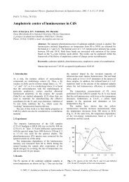
In [57,58] the degradation of both resistivity ρ and charge<br />
carrier mobility µ was studied for n-<strong>GaAs</strong> samples with n =<br />
1.5×10 14 cm -3 . The corresponding ρ(Ô) and µ(Ô) curves are shown<br />
in Fig.2.1. One can see that resistance rise is mainly due to a decrease<br />
of the charge carrier concentration. The ρ(Ô) dependence<br />
is nonlinear and rather complicated. While the crystal conversion<br />
occurs at Ô = 4×10 14 cm -2 , the resistance is doubled at Ô =<br />
4×10 13 cm -2 .<br />
For the crystals of lower resistivity some similar effects were<br />
studied in [59]. The rate of concentration degradation, dn/dÔ,<br />
was 2 cm -2 for the epitaxial layers with n = 2×10 17 cm -3 .<br />
37
Fig.2.1. n-<strong>GaAs</strong> (n = 1.5×10 14 cm -3 )<br />
resistivity (ρ) and mobility<br />
(µ) as a function of fluence<br />
Φ [57].<br />
Shown in Fig.2.2 is the µ(Ô) curve for the same crystal.<br />
One can see that after exposition to a dose of 4×10 15 cm -2 ≅<br />
10 8 rad the drops in concentration n and mobility µ are 4 and<br />
15%, respectively. The µ(Ô) curves for the ion-implanted<br />
structures are also given. The degradation rate for such<br />
structures is twice as that for the epitaxial layers. As was<br />
noted earlier, the rate of radiation defects production is lower<br />
in the structures of higher quality, so a general regularity<br />
seems to take place in this case.<br />
The degradation rates of both mobility µ and concentration<br />
n versus the electron energy were also studied in [59].<br />
The corresponding curves are shown in Figs. 2.3, 2.4.<br />
The interrelation between the two dependencies bears a<br />
qualitative resemblance to the electron energy dependence of<br />
the production rates for the E 1 - E 5 levels. (Generally speaking,<br />
this fact was expected.)<br />
38
Fig.2.2. Percent degradation in drift mobility vs fluence and rad dose for 1 MeV<br />
electron and γ-irradiation for epitaxial and ion-implanted structures [59].<br />
Fig.2.3. Percent degradation in drift mobility as a function of electron energy at<br />
2×10 7 and 10 8 rad (Si) for epitaxial and ion-implanted devices [59].<br />
Since the E 1 - E 5 levels are annealed at 200 0 C, one could expect<br />
that the electrophysical properties of <strong>GaAs</strong> are restored after<br />
the corresponding heat treatment. Indeed, such a restoration was<br />
observed in [60] for the samples with charge carrier concentrations<br />
10 15 - 2×10 17 cm -3 . These results are shown in Figs. 2.5, 2.6.<br />
The heat treatment resulted in restoration (within 10%) of the initial<br />
concentration value for the samples whose charge carrier concentration<br />
dropped by a factor of 2.5 to 7 after irradiation.<br />
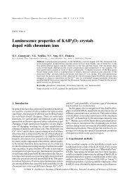
Fig.2.4. Carrier removal at 2×10 7 and<br />
10 8 rad (Si) for different<br />
electron energies in <strong>GaAs</strong><br />
FATFETs fabricated on epitaxial<br />
layers [59].<br />
39
Fig.2.5. Isochronous annealing of<br />
concentration n (1) and<br />
Hall mobility µ (2) [60].<br />
The above holds true only for the crystals exposed to irradiation<br />
by electrons with energy E = 1 MeV. Irradiation of gallium<br />
arsenide with electrons of higher energies results in production of<br />
rather complicated defects which cannot be annealed at 200 0 C<br />
[61].<br />
Shown in Fig.2.7 is the dependence of the fraction of<br />
non-annealed radiation defects on the heat treatment (T =<br />
200 0 C) duration for the samples exposed to either electron<br />
(E = 7.3 MeV) or γ-irradiation (E = 1.25 MeV). One can see<br />
Fig.2.6. Non-annealed defect fraction f vs temperature T for three <strong>GaAs</strong> samples [60].<br />
Fig.2.7. Typical thermal annealing curves of resistor network monitors [61].<br />
40
that in the first case only one-half radiation defects are annealed,<br />
while in the second case the fraction of the annealed defects is as<br />
much as 95%. In addition, the n degradation rate increases with energy<br />
E; e.g., for E = 12 MeV and n = (1-2)×10 17 cm -3 , the n degradation<br />
rate lied in the 9 to 25 cm -1 range for different samples<br />
[62]. This is an order of magnitude greater that the values observed<br />
at E = 1 MeV.<br />
2.1.2. Effect of γ-radiation on <strong>GaAs</strong><br />
As γ-quanta are passing through a semiconductor crystal,<br />
they generate high-energy electrons in it. Interaction between<br />
these electrons and atoms of a sample results in defect generation.<br />
Thus the role of γ-quanta is that of generation of β-radiation<br />
in a sample.<br />
In almost all the investigations only one γ-radiation source<br />
was used, namely, a cobalt gun that provides the quantum energy<br />
of 1.25 MeV. So, in what follows, we shall discuss only the effect<br />
of the γ-quanta of this energy. These quanta generate β-<br />
radiation whose energy lies in the 0 to 1.05 MeV range. The<br />
corresponding spectrum is given in Fig.2.8, along with the<br />
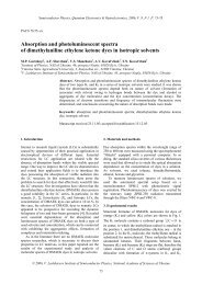
Fig.2.8. Electron flux density from<br />
1.25-MeV γ-rays incident on<br />
n-<strong>GaAs</strong> and possible displacements<br />
per incident<br />
gamma resulting from these<br />
electrons [59].<br />
relative contribution of the electrons of different energies to the<br />
defect generation [59]. One can see that most of the electrons<br />
41
produced do not take part in the defect generation. The mean<br />
defect generation efficiency is considerably below that for the<br />
electrons with E = 1 MeV. The reasons for this are quite apparent<br />
from the previous section. The electrons with energies below<br />
0.6 MeV are insufficient to generate defects in <strong>GaAs</strong>, while the<br />
defect generation probability grows linearly with E for the energies<br />
0.6 < E < 1 MeV. It is also evident that in this case the defects<br />
generated have the same structure as those produced by the<br />
electrons with E = 1 MeV.<br />
For the n-<strong>GaAs</strong> epitaxial layers exposed to γ-irradiation the<br />
degradation rate of electrophysical parameters was measured<br />
in [59] and turned out to be essentially less that in the case of<br />
irradiating a crystal with the electrons having an energy E =<br />
1 MeV. For instance, when the n-<strong>GaAs</strong> epitaxial layers with n<br />
= 2×10 17 cm -3 were exposed to a dose D = 10 8 rad of γ-irradiation,<br />
the charge carrier concentration n decreased by 3×10 14 cm -3 ,<br />
i.e. 15 times less that in the case of β-irradiation [59]. The corresponding<br />
factor for a mobility degradation was 10. (For the<br />
µ(D) dependence see Fig.2.2.) One can see that exposure to a<br />
dose of 10 9 rad results in only 20% drop of the electron mobility.<br />
Degradation of the electrophysical parameters in a n-<strong>GaAs</strong> bulk<br />
was investigated in [62] for the samples with n = (4-7)×10 17 and<br />
2.5×10 16 cm -3 . In the first case the electrophysical parameters remained<br />
unchanged up to a dose of 5×10 8 rad, while in the second<br />
case a drop of 1.26×10 16 cm -3 in the electron concentration was<br />
detected at a dose of 10 9 rad. The electron mobility did not<br />
change in both cases.<br />
To summarize, we can say that the samples with charge carrier<br />
concentration about several units of 10 17 cm -3 can stand up to<br />
10 9 rad of γ-irradiation without substantial changes in their electrophysical<br />
parameters. For lower concentrations the corresponding<br />
limiting dose of γ-irradiation also decreases.<br />
42
2.1.3. Effect of high-energy neutrons on <strong>GaAs</strong><br />
The neutrons passing through a crystal are being scattered<br />
by the crystal atoms. During this scattering (which is due to nuclear<br />
forces) the atoms gain a considerable energy E 1 . The maximum<br />
value of this energy, E 1max , can be found basing on purely<br />
kinematic considerations:<br />
E<br />
4M M<br />
n a<br />
1max<br />
= E0 2<br />
( Mn<br />
+ Ma)<br />
(4)<br />
Here E 0 is the neutron energy, M n (M a ) is the neutron (atom) mass.<br />
Inserting into (4) the value E 0 = 1 MeV (which is typical<br />
for neutron radiation), we get E 1max = 50 keV. This value is<br />
substantially higher than the energy E 2 needed to produce a<br />
point defect: E 2 ≈ 10 - 25 eV [59]. So, a neutron scattering on a<br />
crystal atom leads to a number of atomic collisions. This results<br />
in production of N Def ∼ E 1 /E 2 ∼ 10 3 defects. In other<br />
words, a single act of neutron scattering by a crystal atom<br />
gives rise to a defect region in a crystal. According to calculations<br />
made in [63], the radius r d of this region is about 20<br />
nm and the concentration of generated defects is<br />
3 20 −3<br />
n ≈ 3N / 4πr<br />
≈10<br />
cm .<br />
Def Def d<br />
Since the energy transmitted to the crystal lattice from the<br />
neutrons is rather high, a great diversity of radiation defects occurs<br />
in a crystal irradiated [37,46,48,51,64]. In principle, the whole<br />
variety of defects found in the electron-irradiated <strong>GaAs</strong> is generated<br />
in this material also by the neutron radiation.<br />
Annealing of the crystal damage produced by neutron irradiation<br />
proceeds in three stages. Two of them have been discussed<br />
before. They are observed at room temperature and at 220<br />
0<br />
C, respectively, and are related to the annihilation of the Frenkel<br />
pairs in the Ga and As sublattices. The third stage occurs at 500<br />
0<br />
C. It is determined by the As vacancies migration over the crys-<br />
43
tal. As this takes place, most of the radiation defects are being<br />
healed up.<br />
Intuition suggests that a free charge carrier concentration in<br />
the defect regions must drop, while the probability of the charge<br />
carrier scattering must grow. When analyzing the macroscopic<br />
properties of crystals, the appearance of such defect regions may<br />
be treated as a decrease in both the free charge carrier mobility µ<br />
and their average concentration n. Such an approach remains<br />
valid as long as the geometric sizes of the structures studied are<br />
vastly larger than the radii of the defect regions.<br />
The regularities of n and µ degradation in both <strong>GaAs</strong> bulk<br />
and epitaxial films under neutron irradiation are well known. The<br />
corresponding dose dependencies may be expressed as follows:<br />
n = n 0 (1 - αÔ), α = 7.2×10 -4 n 0<br />
-0.77<br />
(5)<br />
µ = µ 0 (1+bÔ) -1 , b = 7.8×10 -6 n 0<br />
-0.64<br />
(6)<br />
Here n 0 (µ 0 ) is the initial electron concentration (mobility), n(µ) is<br />
the electron concentration (mobility) after neutron irradiation, Ô<br />
is the neutron irradiation integrated fluence.<br />
The above expressions hold at low Ô values; besides, it is assumed<br />
that αÔ . bÔ
The integrated fluence dependence of the electron concentration<br />
may be expressed as<br />
n = n0 e αΦ (7)<br />
For the ion-implanted <strong>GaAs</strong> layers the situation with both n<br />
and µ changing during neutron irradiation is less clear. The results<br />
obtained by different authors are often inconsistent with<br />
each other. For instance, in [65] the following expression was<br />
obtained for the n degradation with Φ:<br />
n = n 0 (1 - αΦ), α = 1.91×10 -4 n 0<br />
-1.33<br />
(8)<br />
For n 0 = 10 17 cm -3 this expression gives the concentration<br />
degradation rate about 20 times as great as that given by the expression<br />
(5). The electron concentration n was found from the<br />
results of the Hall effect measurements. The dn/dÔ dependencies<br />
on n for both ion-implanted layers and a bulk material are<br />
given in Fig.2.10.<br />
−<br />
Fig.2.10. The resistor damage<br />
factor as a function of<br />
carrier concentration<br />
under neutron bombardment;<br />
ο - epitaxial<br />
layers [130], × - ionimplanted<br />
layers [65].<br />
In [66] another expression for n(Ô) was found, with<br />
α = 2.6×10 -3 -0.77<br />
n 0 (9)<br />
i.e. the same α(n) dependence as for <strong>GaAs</strong> bulk (5) but with the<br />
numerical coefficient 3.6 times greater. In that paper the n degradation<br />
was calculated from the pinchoff voltage shift in the p-n<br />
45
junction FETs (JFET). The expression (9) was tested also in [67]<br />
for SFETs with the maximum n 0 value of 2×10 17 cm -3 . It was found<br />
that the departure from the results calculated from (9) did not<br />
exceed 10%. For the case αΦ ≥ 1 the integrated fluence dependence<br />
of electron concentration, n(Φ), was also studied in [67]. The<br />
following expression was obtained:<br />
n( Φ)<br />
n0<br />
=<br />
1 + αΦ<br />
46<br />
(10)<br />
According to (5), (6), in <strong>GaAs</strong> bulk the concentration n is degrading<br />
faster that mobility µ. Indeed, for n = 10 17 cm -3 the ratio<br />
b/α is 1.8. In the case of ion implantation the situation is just the<br />
contrary. The authors of [67] reason that the rise in sample resistance<br />
is mainly due to the n drop. The electron mobility µ measured<br />
in [67] remained practically the same at Φ ≤ 2×10 15 cm -<br />
2<br />
while, in accordance with (6), it was to drop by 20%. In that paper<br />
the µ/µ 0 ratio was found from an analysis of the FET electrical<br />
characteristics.<br />
Now, a few words about a combined (neutron- plus γ-<br />
radiation) action on the ion-implanted layers. Since there is the<br />
only paper, [67], on this subject, one should carefully treat its<br />
results. At the same time it should be noted that these results are<br />
of major interest.<br />
The authors of [67] investigated the ion-implanted <strong>GaAs</strong> layers.<br />
The average electron concentration value was 7.4×10 16 cm -3 . The γ-<br />
irradiation dose of (2 - 4)×10 7 rad did not change the parameters<br />
of the structure studied to within 4%. Three types of sample<br />
treatment were used: (i) neutron irradiation; (ii) the same as (i)<br />
followed by heat annealing at 150 0 C; (iii) the same as (ii) followed<br />
by γ-irradiation (dose of 2×10 7 rad).<br />
The degradation of charge carrier mobility is shown in<br />
Fig.2.11 for all the three treatments. One can see that neutron<br />
irradiation has changed the electron mobility but little; the following<br />
heat annealing has undone that small change, but the γ-
irradiation has resulted in an abrupt µ drop. Thus, a combined<br />
action of neutrons and γ-quanta leads to the degradation of the<br />
structures studied, despite the fact that each of these factors<br />
alone hardly affects the electron mobility.<br />
Fig.2.11. Mobility degradation µ/µ 0<br />
vs neutron fluence Φ :<br />
1-before heat annealing;<br />
2-after heat annealing;<br />
3-after heat annealing followed<br />
by γ-irradiation [67].<br />
The above results may be summarized as follows. The ionimplanted<br />
<strong>GaAs</strong> layers are less resistant against neutron irradiation<br />
than either epitaxial structures or the <strong>GaAs</strong> bulk. For neutron-irradiated<br />
ion-implanted layers the degradation rate of their<br />
electrophysical parameters seems to depend on the technological<br />
procedure used in the layer fabrication. The same is also true for<br />
ion-implanted structures irradiated with high-energy electrons.<br />
So, a general regularity seems to exist which is independent of<br />
the type of radiation used. This fact is not understood yet and<br />
deserves further investigation.<br />
Up to this point we were discussing the effect of the energy<br />
spectrum of neutron stream on the electrophysical parameters<br />
degradation in <strong>GaAs</strong>. At the same time not only the energy E 1<br />
(gained by the crystal atoms during the neutron scattering) grows<br />
with the neutron energy E 0 , but also the number of defects generated,<br />
N Def . This number is usually taken to be proportional to<br />
the energy E d which is going into the defect generation. Then the<br />
47
defect concentration, n Def (proportional also to the integrated fluence,<br />
Φ, and to the neutron scattering cross section, σ) is given<br />
by the following expression:<br />
n Def ≈ ΦD’, D’ = σE d (11)<br />
The energy E d is not equal to the total energy absorbed by<br />
the crystal during a single scattering act, because some part of<br />
the latter energy goes into the atoms ionization. Within the<br />
framework of the above model, two neutron streams, of the energies<br />
E 1 and E 2 , respectively, lead to equivalent changes in the electrophysical<br />
properties of the irradiated samples, if a condition<br />
Φ(E 1 )D’(E 1 ) = Φ(E 2 )D’(E 2 ) (12)<br />
holds. The D’ value depends on the material studied. It is well<br />
known for silicon. A 1 MeV equivalent fluence Ô 0 obtained from<br />
the expression<br />
Φ<br />
Φ0<br />
= ∫ ( ) '<br />
EDSidE<br />
(13)<br />
'<br />
DSi( 1MeV)<br />
is usually cited in the literature on silicon. Of course, use of this<br />
value when analyzing the experimental results for <strong>GaAs</strong> seems<br />
incorrect. Therefore the papers [63,68] where D’ was calculated<br />
for <strong>GaAs</strong> are of special interest. The results of calculations are<br />
shown in Fig.2.12. (The D’ value tables for <strong>GaAs</strong> are given in<br />
[69].) In [68] it was shown that insertion of D’ si , instead of D’ <strong>GaAs</strong> ,<br />
Fig.2.12. <strong>GaAs</strong> semiconductor<br />
Kerma (Kinetic Energy<br />
Released in<br />
MAterial) vs neutron<br />
energy: 1 -<br />
kinematic Kerma<br />
limit, 2 - displacement<br />
Kerma [63].<br />
48
into the expression (13) leads to an error that may be as much<br />
as 50%.<br />
Strictly speaking, one should first assure oneself that the expression<br />
(13) is valid (taking into account that it was obtained<br />
under rather arbitrary assumptions). Such a checking was made in<br />
[68], where the degradation rate of electron concentration,<br />
dn/dΦ, was measured using three different neutron sources. The<br />
corresponding results are given in Table 2.2.<br />
Table 2.2. Dependence of the electron concentration degradation rate on the<br />
neutron energy for the neutron-irradiated <strong>GaAs</strong> samples<br />
Average neutron<br />
energy,<br />
MeV<br />
10 24 D’,<br />
MeV . cm 2<br />
Electron concentration<br />
degradation rate,<br />
dn/dÔ, cm -1<br />
0.757 42.1 8<br />
1.30 65.7 9<br />
14.9 273 27<br />
From this Table it is evident that dn/dÔ is not proportional<br />
to D’. This fact seems to be due to the interaction between defects.<br />
Such an explanation looks reasonable, taking into account<br />
high defect concentrations in the defect regions. One can conclude<br />
from the above that a special care is required when comparing<br />
the results obtained using different neutron sources.<br />
2.1.4. Effect of thermal neutrons on <strong>GaAs</strong><br />
When passing through the <strong>GaAs</strong> crystal, thermal neutrons<br />
enter into the reactions with the Ga and As nuclei which result in<br />
the following transmutations:<br />
As 75 → As 76 → Se 76 ; Ga 69 → Ga 70 → Ge 70 ; Ga 71 → Ga 72 → Ge 72<br />
If the Se(Ge) atoms formed by these reactions remain in the<br />
49
As(Ga) sublattice, they behave like donors. The concentration of<br />
such donors is given by the following expression [70]:<br />
N d = kΦt, (14)<br />
where t is the duration of neutron irradiation and k = 0.16 cm -1 s -1 .<br />
However, the atoms formed as a result of the nuclear reactions<br />
gain considerable energies and usually do not remain on<br />
their initial spots. That is why the expression (14) begins to hold<br />
only after a high-temperature annealing.<br />
The above method of neutron transmutation doping is promising<br />
for use in semiconductor technology. Such a method could<br />
be used to obtain crystals with the exactly predetermined concentrations<br />
of donors uniformly distributed over the crystal. Unfortunately,<br />
the crystals exposed to neutron transmutation doping<br />
turn out to be compensated. The matter is that some portion of<br />
Ge atoms is brought into the As sublattice after the hightemperature<br />
annealing. Such atoms act as acceptors. Presence of<br />
such atoms is confirmed by the photoluminescence (PL) spectra<br />
[71,72]. These spectra have a band corresponding to the transition<br />
from the conduction band to the acceptor level [71,72].<br />
The compensation degree depends on the annealing procedure.<br />
In [72] it was proposed to use pulse annealing (duration of<br />
10 s). Such annealing was realized using halogen incandescent<br />
lamps. The results of investigations carried out for two groups of<br />
samples (differing in the neutron dose absorbed) are given in Table<br />
2.3. They clearly demonstrate the advantages of pulse annealing<br />
over standard one.<br />
The sources used in neutron transmutation doping emit<br />
(along with thermal neutrons) also a small portion of high-energy<br />
neutrons. The role of the latter in neutron transmutation doping<br />
was studied in [73]. It was shown that if a fraction of high-energy<br />
neutrons in the total neutron stream is large (20 - 30%), then the<br />
sample resistance drops abruptly after annealing at 600 0 C.<br />
50
For small (0.3%) fraction of high-energy neutrons this drop<br />
was observed after annealing at T = 400 0 C.<br />
Table 2.3. Charge carrier concentrations n, mobilities µ and<br />
compensation degrees after different annealings<br />
Sample group<br />
number<br />
Annealing<br />
type<br />
n, 10 17<br />
cm -3 µ, cm 2 V -1 s -<br />
1<br />
Compensation<br />
degree<br />
1 standard 2 3600 0.5 - 0.6<br />
1 pulse 2.2 4700 0.25<br />
2 standard 12 1650 0.75<br />
2 pulse 15 2400 0.6<br />
2.2. EFFECT <strong>OF</strong> γ-<strong>RADIATION</strong> ON IMPERFECT STRUCTURES<br />
AND INTERFACES<br />
To this point we considered, for the most part, the interaction<br />
between the ionizing radiation and a perfect <strong>GaAs</strong> crystal which<br />
was in the state of thermodynamic equilibrium. Numerous defects<br />
occurring in actual structures, as well as various effects at the<br />
interfaces, were ignored in the above discussions. Of course,<br />
some isolated facts were mentioned which were beyond the scope<br />
of our consideration, such as low radiation resistance of ionimplanted<br />
layers, the possibilities of generation of complexes<br />
formed by radiation defects and impurity atoms, dependence of<br />
the defect production rate on the doped layer growth technology,<br />
etc. However, a comprehensive consideration of these, as well as<br />
related, problems was not performed. Now we shall try to close<br />
this gap.<br />
As was stated above, exposure to ionizing radiation is a<br />
rather universal tool for changing the physico-chemical state of<br />
51
the material. The extent of structural and chemical changes in<br />
semiconductor materials may vary over wide limits, depending on<br />
the type and energy of the radiation used and the dose absorbed.<br />
The above changes are proceeding more intensely near the interfaces,<br />
so this fact must substantially influence the physicochemical<br />
properties of the contact heteropairs.<br />
2.2.1. Effect of γ-radiation on the Pt - <strong>GaAs</strong> heterostructure<br />
Let us now discuss the effect of radiation on the Me - <strong>GaAs</strong><br />
interfaces. As a result of the radiation-stimulated diffusion of the<br />
heteropair components, the concentration depth profiles of Me,<br />
gallium and arsenic in the transition region change. This was observed<br />
for Au - Ti - <strong>GaAs</strong> [74] and Pt - <strong>GaAs</strong> [75,76] heterostructures<br />
exposed to γ-irradiation. In both cases the concentration<br />
depth profiles in the transition region were taken with XPS combined<br />
with layer-by-layer ion etching. Considerable changes in<br />
these profiles were observed at irradiation doses 10 5 Gy. In Pt -<br />
<strong>GaAs</strong> heterostructures these changes substantially depended on<br />
the voltage across the Schottky barrier.<br />
Shown in Fig.2.13 are typical concentration depth profiles of<br />
the components of Pt - <strong>GaAs</strong> contact pair, taken before and after<br />
its exposure to 60 Co γ-irradiation.<br />
Fig.2.13. Concentration depth profiles for a Pt - <strong>GaAs</strong> contact: a - initial, b - after<br />
γ-irradiation (dose of 10 5 Gy). Time of ion etching is given in h [77].<br />
52
One can see that γ-radiation considerably affects the parameters<br />
of the contact transition region. To analyze the reasons<br />
and mechanisms of the above changes, we have taken XPS spectra<br />
of both (cation and anion) <strong>GaAs</strong> components during the process<br />
of contact etching (Figs. 2.14, 2.15). One can see that Ga 2p,<br />
as well as As 3d, spectra have complicated profiles and are considerably<br />
broadened.<br />
Fig.2.14. XPS results for Ga 2p (a) and As 3d (b) atomic levels taken after<br />
layer-by-layer ion etching of the initial Pt - <strong>GaAs</strong> contact. Time of<br />
ion etching: 1 - 1; 2, 1' - 1.5; 3, 2' - 2; 3' - 2.5 h [77].<br />
Fig.2.15. The same as in Fig.3.14 but for the γ-irradiated Pt - <strong>GaAs</strong> contact.<br />
Time of ion etching: 1 - 0.5; 2, 1' - 1; 2' - 1.5; 3, 3' - 2h [77].<br />
53
This is an evidence that both structure and composition of<br />
the transition region (whose origin was analyzed in [77,78]) are<br />
nonuniform. Heat treatment, as well as heating of semiconductor<br />
during adsorption of Me (platinum) atoms and their clusterization<br />
also lead to <strong>GaAs</strong> decomposition. The above processes may considerably<br />
affect the structure of the transition layer. Still the bombardment<br />
of the semiconductor surface and growing metal film<br />
by the accelerated metal particles from the metal vapor is even<br />
more substantial. Not only the presence of high-energy evaporated<br />
particles is characteristic of the electron-beam evaporation,<br />
but also the presence of ions whose mean energy may be as<br />
much as several tens eV. Generation of a pair of defects in the<br />
<strong>GaAs</strong> bulk at 300 0 C needs ≈ 10.1 eV. So the above reason for<br />
structural disordering may be very substantial [79,80]. Still it remains<br />
beyond the control in semiconductor technology. All the<br />
above factors favor the interaction between phases which results<br />
in <strong>GaAs</strong> decomposition and the interface movement into the<br />
crystal bulk.<br />
The effective charges of Ga and As atoms, as well as binding<br />
energies E b of the core electrons, depend on a number of factors<br />
(such as changes in valency, coordination numbers, bonding type,<br />
chemical surroundings) which characterize the appearing transition<br />
layer. That is why one cannot identify the chemical state of<br />
the semiconductor components from the Fig.2.15 spectra only.<br />
During further γ-irradiation the transition region width decreases<br />
by a factor of 2 - 3. This means that the concentration<br />
depth profiles become more abrupt. And the XPS spectra of both<br />
Ga and As core electrons also change. Shown in Figs. 2.14, 2.15<br />
are the XPS spectra of Ga 2p and As 3d core electrons for the<br />
initial and irradiated samples. One can see that after γ-irradiation<br />
the spectral lines become more symmetric, while the spectra<br />
structure becomes less complicated. This is an evidence for<br />
chemical ordering at the interface. In this case an analysis of the<br />
54
changes in binding energies E b of the Ga 2p and As 3d core<br />
electrons, the observed chemical shift of the Pt 4f level, as well as<br />
the results of [81-83], enabled to determine the chemical phases<br />
that predominate in the contact transition region.<br />
As can be concluded from Figs. 2.14, 2.15, the form of Ga 2p<br />
line does not change as the contact is being stripped with a solvent,<br />
while its peak position is shifted within a rather narrow energy<br />
interval. This indicates that the chemical state of Ga atoms<br />
changes but little in the transition region of the Pt - <strong>GaAs</strong> structure.<br />
The Ga 2p line appearing in the XPS spectra at 1117.9 -<br />
1118.6 eV binding energies was reported in [81,83] to be characteristic<br />
of gallium oxides. Taking account of the binding energy<br />
value one can conclude that Ga 2 O 3 is predominant in the contact<br />
transition region [83].<br />
Identification of arsenic compounds presents a far more complicated<br />
problem. This is because both the peak position and the<br />
form of As 3d line change (see Figs. 2.14, 2.15). This fact indicates<br />
that a number of arsenic phases (differing in their chemical<br />
nature) are present in the contact transition region. From Figs.<br />
2.14, 2.15 one can see that, as the contact is being stripped with a<br />
solvent, the As 3d line is shifted within the 41.1 to 41.9 eV energy<br />
range. This enables one to conclude (in accordance with the results<br />
of [81-83]) that there are at least two states of arsenic atoms<br />
in the contact transition region. These are the chemically nonbound<br />
atoms (E b = 41.9 eV) and those forming intermetallic<br />
compounds (E b = 41.1 - 41.3 eV). The data presented in Figs.<br />
2.14, 2.15 are not sufficient to identify with confidence these<br />
compounds, because the energy position of the As 3d line (determined<br />
with XPS) coincides with that in <strong>GaAs</strong> [81,82]. However,<br />
the chemical shift of Pt 4f line (which is most pronounced in the<br />
region adjacent to the semiconductor and equals to ≈ 0.5 - 0.8<br />
eV), as well as clearly defined changes in the As 3d line structure<br />
(see Figs. 2.14, 2.15), suggest presence in the transition region of<br />
55
a Pt - As compound. This may be PtAs 2 whose formation was detected<br />
in the Pt - <strong>GaAs</strong> contacts after low-temperature heat annealing<br />
[84,85].<br />
Hence in the transition region of the γ-irradiated Pt - <strong>GaAs</strong><br />
contact there are: arsenic (both free and chemically bound to<br />
platinum) and gallium (predominantly entering into Ga 2 O 3 ). It<br />
should be noted that both Ga 2 O 3 and As are present throughout<br />
the entire transition region, while the PtAs 2 phase is localized<br />
predominantly near the semiconductor.<br />
The obtained results make it possible to draw some conclusions<br />
concerning the physico-chemical processes that occur during<br />
formation of the Pt - <strong>GaAs</strong> interface under 60 Co γ-irradiation.<br />
As was stated before, the interaction between γ-radiation and<br />
solids results in electron generation (photoeffect, Compton effect).<br />
Most of these electrons have energies of several thousands<br />
of eV. Moving in a crystal bulk, such electrons can produce point<br />
defects and change electronic configuration of atoms. The latter<br />
effect can be favored also by the secondary electrons resulting<br />
from the interaction between the primary electrons and the metal<br />
(or semiconductor) atoms. Taking into account the aforesaid, as<br />
well as the fact that chemically disordered transition region is<br />
metastable, one can assume that the point defect gettering is not<br />
the only process taking place in the γ-irradiated Pt - <strong>GaAs</strong> contacts.<br />
A structural-chemical ordering of the interface due to formation<br />
of more stable compounds also can occur there. It was<br />
proved above that PtAs 2 and Ga 2 O 3 are the predominant compounds.<br />
Still, according to [86], some more phases may be<br />
formed in the contact transition layer. Eight (one) compounds<br />
made by Pt and Ga (As) are known; some of them are unstable.<br />
Conversion of low-stable phases into high-stable ones results in<br />
changing both chemical composition and morphology of the transition<br />
layer. This promotes formation of a more close-packed<br />
structure.<br />
56
Thus γ-irradiation substantially affects the spreading, stoichiometry<br />
and phase composition of the Pt - <strong>GaAs</strong> interface. The<br />
above results allow to conclude that under these conditions the<br />
barriers with improved parameters are formed. To verify this conclusion,<br />
we have taken I - V and C - V curves for the Pt - <strong>GaAs</strong><br />
structures exposed to the irradiation doses from 10 3 to 10 6 Gy.<br />
Such measurements can provide an immediate evidence concerning<br />
the contact quality. The contact parameters found from<br />
the I - V and C - V curves are given in Fig.2.16. One can see that<br />
γ-irradiation of Schottky diodes reduces both the ideal-<br />
Fig.2.16. γ-irradiation dose dependencies of the Schottky barrier height ϕ B ,<br />
ideality factor n and reverse current I R for a Pt - <strong>GaAs</strong> contact (the<br />
metal electrode area is about 2×10 -5 cm 2 ) [77].<br />
ity factor n and the reverse current I R , while increasing the barrier<br />
height ϕ B . The fact of structural-chemical ordering of the interface<br />
under γ-irradiation (that is evident from the above discussion of<br />
the features in both the electrophysical parameters and the<br />
physico-chemical characteristics changes for the transition layer)<br />
is also confirmed by the results of investigations using the structures<br />
exposed to combined (radiation + electric field) treatments<br />
[87].<br />
57
2.2.2. Effect of γ-radiation on the Cr - <strong>GaAs</strong> heterostructure<br />
The above contact parameters (n, I R and ϕ B ) depend on both<br />
the chemical composition and the structure of the contact transition<br />
layer. However, in some cases there is no correlation between<br />
the parameter changes and the results of the contact layerby-layer<br />
analysis (which could represent the character of interactions<br />
between phases). The behavior of Cr - <strong>GaAs</strong> contacts under<br />
γ-irradiation [88-92] can serve as an evidence for the above<br />
statement.<br />
Shown in Fig.2.17 are the concentration depth profiles of the Cr<br />
- <strong>GaAs</strong> heteropair components in the contact transition region.<br />
Fig.2.17. Concentration depth profiles of the Cr - n-n + - <strong>GaAs</strong> structures<br />
before (a) and after (b - 10 3 , c - 10 4 , d - 10 5 Gy) γ-irradiation. 1 - C, 2<br />
- N, 3 - O (uncontrollable contaminations), 4 - Cr, 5 - Ga, 6 - As.<br />
Time of ion etching t is given in min. [88].<br />
58
They were taken for both the initial and γ-irradiated Cr -<br />
<strong>GaAs</strong> structures. (The dose rate was 3 Gy/s.) Cr atoms interact<br />
with the semiconductor substrate (as Pt atoms did in the Pt -<br />
<strong>GaAs</strong> heteropair). This results in formation of extended diffuse<br />
regions where the contact pair components are intermixed. The<br />
width of such a region changes with γ-irradiation of the contact.<br />
To make an estimate of the transition region width, we defined it<br />
as the distance between the two planes (parallel to the interface<br />
plane) at which the concentrations of a given component (measured<br />
from the intensity of the corresponding Auger line) are 90<br />
and 10% of the value at the plateau. (For Cr this is the value in<br />
the metal film sufficiently far from the interface plane, while for<br />
Ga and As these are the values in the semiconductor substrate,<br />
sufficiently far from the interface plane.) In Table 2.4 the contact<br />
transition region widths (estimated from the AES spectra of principal<br />
heteropair components) are given.<br />
Table 2.4. Transition region widths (nm) for the Cr - <strong>GaAs</strong> contacts<br />
before and after 60 Co γ-irradiation<br />
Heteropair Initial Dose absorbed, Gy<br />
component sample 10 3 10 4 10 5<br />
Cr 12 26 20 14<br />
Ga 12 21 18 14<br />
As 9 27 17 16<br />
They were estimated assuming that the etching rate did not<br />
change during the ion-etching process (i.e., this rate was taken to<br />
be the ratio between the metal film thickness and the time<br />
needed for the film to be completely stripped). One can see from<br />
Table 2.4 that at small (10 3 Gy) doses of γ-irradiation the transition<br />
region width grows (it is twice as large as the initial ones for<br />
Cr and Ga, and three times as large as the initial one for As). As<br />
59
the dose absorbed by the sample grows, the transition region<br />
width begins to decrease. At the dose absorbed of 10 5 Gy the<br />
transition region width is rather close to that in the initial (before<br />
γ-irradiation) sample.<br />
Change of the transition region width under γ-irradiation is<br />
very unusual. Both the rate of this changing and its nonmonotonous<br />
character are unexpected. Generally speaking, they may be<br />
due to the following factors: (i) radiation-stimulated quasichemical<br />
reactions between the Me atoms and those of semiconductor<br />
components; and (ii) radiation-stimulated diffusion of the heteropair<br />
components, accompanied by the radiation-induced stress<br />
relaxation in the samples studied.<br />
It seems to us that the first of the above factors does not<br />
have a pronounced effect on the diffusion redistribution in the Cr<br />
- <strong>GaAs</strong> transition region. There are no features in the concentration<br />
depth profiles of the heterocontact components (see Fig.2.17)<br />
that could be attributed to the appearance of new chemical<br />
phases. In addition, all the values of the transition region width<br />
obtained from the profiles of different components change in the<br />
same way.<br />
So, the second factor seems more likely to us. While the radiation-stimulated<br />
growth of the diffusion coefficients provides<br />
high rate of the profiles spreading at rather low (up to 10 3 Gy)<br />
doses of γ-irradiation, the stress relaxation at higher (10 4 and<br />
10 5 Gy) doses may be responsible for the “uphill” diffusion (i.e.,<br />
the movement of component atoms in the direction of their concentration<br />
growth).<br />
Figure 2.17 shows the concentration profiles of Cr in the<br />
transition region before and after γ-irradiation. One can see that<br />
the dose of 10 3 Gy made the profile less precipitous, the transition<br />
region becoming significantly wider that in the initial profile. This<br />
points to considerable radiation-stimulated mass transport.<br />
60
To make an approximate estimate of the effective diffusion<br />
coefficient of Cr we used the Fick equation<br />
∂c<br />
∂ ⎛ ∂<br />
∂t ∂x D c ⎞<br />
= ⎜ ⎟ (15)<br />
⎝ ∂x<br />
⎠<br />
Here, c is the concentration of Cr atoms, t is the time of diffusion,<br />
and x is the coordinate along the normal to the interface. We<br />
made a simplifying assumption that the diffusion coefficient<br />
changed abruptly at a certain depth in the transition region, thus<br />
D(c) =<br />
⎧D1 for c ≤ cx<br />
⎨<br />
⎩D2<br />
for c > c<br />
x<br />
(16)<br />
The measured depth profile of the initial, nonirradiated sample<br />
was approximated piece-wise by polynomials. Then the obtained<br />
profile was used as an initial condition needed to solve<br />
equation (15). In the first approach we assumed that the time of<br />
radiation-stimulated diffusion was equal to the duration of radiation<br />
treatment. It should be added here that γ-radiation did not<br />
cause sample heating above 50 0 C.<br />
For roughly estimated values of D 1 , D 2 and c x we solved the<br />
Fick equation numerically. The agreement between the obtained<br />
curve and the experimental depth profile was assessed in terms of<br />
the mean square deviation. The three unknown parameters D 1 , D 2<br />
and c x were obtained iteratively by repeating the numerical solution<br />
and minimizing the standard deviation.<br />
The retrieved values of D 1 and D 2 are 5.3×10 -19 and 8.2×10 -20<br />
m 2 s -1 , respectively. On the assumption that the diffusion coefficient<br />
was constant throughout the whole sample, a coarser estimate<br />
gave a value of 5×10 -19 m 2 s -1 . The third parameter, c x , (unlike<br />
D 1 , D 2 ) has a purely mathematical, not a physical meaning. One<br />
can observe that the effective coefficient of radiation-stimulated<br />
Cr diffusion is higher by many orders of magnitude than that of<br />
ordinary, non-assisted diffusion of Cr in <strong>GaAs</strong> at the same temperature.<br />
The obtained effective diffusion coefficients reach the<br />
61
values reported for Cr diffusion in <strong>GaAs</strong> at much higher temperatures<br />
(600 to 700 0 C) [93].<br />
The shapes of Ga and As profiles were characterized in a<br />
similar way. It was very interesting to observe that while the lowest<br />
used dose 10 3 Gy caused a broadening of the depth profile,<br />
higher doses of radiation (10 4 and 10 5 Gy) made the depth profiles<br />
steeper than the profile after the lowest administered dose<br />
(10 3 Gy). We had observed a similar behavior also in Mo - <strong>GaAs</strong><br />
and Pt - <strong>GaAs</strong> contacts [75].<br />
There are several sources of stress in metallic condensates<br />
interacting with semiconductor substrates. First, it is the initial<br />
macroscopic bending of the sample, second, the difference between<br />
the atomic radii of semiconductor constituents and metal<br />
atoms penetrating into the substrate, and third, the differences in<br />
elastic moduli of metal and semiconductor and between the temperatures<br />
at which the contact was deposited and that at which<br />
the measurements are conducted. The stresses of different origins<br />
may act in opposite directions.<br />
Mathematically, in the presence of mechanical stress σ, the<br />
flux of Cr atoms can be expressed as [75,94]<br />
j =− ⎛<br />
D dc c d<br />
dx<br />
− Ω<br />
kT<br />
⋅ σ ⎞<br />
⎜<br />
⎟<br />
(17)<br />
⎝ B dx ⎠<br />
where D is the effective diffusion coefficient and Ω is the change<br />
in the elementary cell volume of <strong>GaAs</strong> due to insertion of a Cr<br />
atom into this cell. In the case of substitutional impurities, Ω is<br />
simply the difference between atomic volumes of impurity and<br />
matrix atoms and can be both positive and negative. All remaining<br />
symbols have their usual meanings.<br />
The internal mechanical stress consists of two components:<br />
σ = σ 0 + σ d (18)<br />
Here, σ 0 is the initial internal stress existing in the system already<br />
prior to the onset of radiation-stimulated diffusion and σ d is the<br />
62
concentration dependent stress originating from the insertion of<br />
foreign Cr atoms into the host matrix of <strong>GaAs</strong>, thus from the ongoing<br />
diffusion itself. This term can be expressed as<br />
σ d = - Kβc (19)<br />
where K is the modulus of uniform (“hydrostatic”) compression<br />
and β is the coefficient of the host matrix expansion due to<br />
penetration of diffusing particles. Therefore equation (17) takes<br />
the form<br />
⎡<br />
j D dc ⎛ KβΩc⎞<br />
Ωc<br />
dσ 0 ⎤<br />
=− ⎢ ⋅⎜1<br />
− ⎟ + ⋅<br />
⎣dx<br />
⎝ kT⎠<br />
kT B dx ⎥<br />
B<br />
⎦<br />
(20)<br />
Even though the magnitude of β for Cr in <strong>GaAs</strong> is unknown,<br />
one can estimate that β ≥ 10 -30 m 3 (this is the order of<br />
magnitude of β for atoms whose radii are closer to the atomic<br />
radii of Ga and As than that of Cr). Hence, at high concentrations<br />
and at low temperatures it holds KβΩc > k B T and diffusion<br />
of Cr into <strong>GaAs</strong> would not take place at all, if it were not<br />
for the last term in the square brackets on the right side of<br />
equation (20). Partial stress relaxation, and thus, removal of<br />
the initially present stress σ 0 by γ-irradiation, cancels this term<br />
out, which eventually changes the sign on the right side of<br />
equation (20), giving rise to anomalous “uphill” diffusion.<br />
As in the case of Pt - <strong>GaAs</strong> structures, the modification of Cr<br />
- <strong>GaAs</strong> contacts under γ-irradiation leads to changes in the parameters<br />
of the corresponding diode structures. Shown in Fig.2.18<br />
are the barrier height ϕ B , the ideality factor n and the reverse current<br />
I R in the Cr - <strong>GaAs</strong> diode structures versus the absorbed<br />
dose of γ-radiation. All the above parameters change with dose<br />
similarly to those in the Pt - <strong>GaAs</strong> diode structures (Fig.2.16).<br />
There is some discrepancy, however, between these changes and<br />
the results of the layer-by-layer studies. Trying to establish a cor-<br />
63
elation between the results of the layer-by-layer analysis and<br />
the chosen electrophysical parameters of diode<br />
Fig.2.18. γ-irradiation dose dependencies of the Schottky barrier height ϕ B<br />
(∆), ideality factor n (•) and reverse current I R (ο) for a Cr - n-n + -<br />
<strong>GaAs</strong> Schottky diode [88].<br />
structures, we performed investigations of the interface between<br />
<strong>GaAs</strong> and chemically “inert” Mo layer.<br />
2.2.3. Effect of γ-radiation on the Mo - <strong>GaAs</strong><br />
heterostructure<br />
Thin Mo layers can serve as a good buffer in the contacts<br />
with multilayer metallization. These layers are stable against oxidation.<br />
Electronegativity of molybdenum is much less than that of<br />
arsenic. This fact must provide a small width of the transition region.<br />
Typical Mo, Ga, As and O (uncontrollable contamination)<br />
concentration depth profiles, taken using the layer-by-layer<br />
etching of Mo - <strong>GaAs</strong> contact just after its preparation, are shown<br />
in Fig.2.19. From these profiles one can conclude that during Mo<br />
deposition onto a <strong>GaAs</strong> substrate an interpenetration of different<br />
contact components takes place. (The same was observed also in<br />
Pt(Cr) - <strong>GaAs</strong> heterostructures.) As a result, a Me - semiconductor<br />
interface is spreading. When discussing such an interaction<br />
64
etween phases, it is of importance to find out the contributions<br />
of various phases into the diffusion spreading of an<br />
Fig.2.19. Concentration depth profiles of the Mo - n-n + -<strong>GaAs</strong> structures: a -<br />
initial; b, c - after 60 Co γ-irradiation, doses of 10 4 and 10 5 Gy, respectively.<br />
Time of ion etching t is given in min.<br />
interface. Study of the Mo - <strong>GaAs</strong> contact pair enabled us to<br />
tackle the above question.<br />
To estimate relative contributions of both Me and semiconductor<br />
components atoms into the contact formation, one can<br />
invoke the data concerning both gallium and arsenic oxide layers<br />
on the <strong>GaAs</strong> surface. Indeed, for <strong>GaAs</strong> the heat of formation is<br />
19.5 kcal/mole, while for Ga 2 O 3 and As 2 O 5 it is 259 and 156<br />
65
kcal/mole, respectively [95]. This indicates that in both oxides<br />
chemical binding is stronger than in <strong>GaAs</strong>. Besides, substitution<br />
of Ga and As in their oxides by Mo goes with low intensity. So<br />
one can assume that at any treatment a thin oxide layer on the<br />
<strong>GaAs</strong> surface is retained, thus fixing the surface position. It is<br />
notable that the position of the oxygen concentration peak in the<br />
transition region does not necessarily lie at a plane where molybdenum<br />
concentration is half its value at a plateau - see Fig.2.19.<br />
(It looks natural to consider this plane as coinciding with the interface<br />
plane.)<br />
Starting from the above, one can list a number of features<br />
that determine interfacial structure and composition. There is no<br />
straightforward exchange mechanism of the heteropair components<br />
diffusion across the interface. This is evident from the fact<br />
that the heteropair components flows across the interface are<br />
different. Mo is spreading more intensely than Ga and As, forming<br />
a more extended diffuse region. The penetration depths of<br />
both Ga and As into the Mo film are substantially less. So, one can<br />
assume that the rate-determining factors in the formation of a<br />
boundary between phases are related to the diffusion of semiconductor<br />
components whose solubilities in molybdenum are low.<br />
From Fig.2.19 one can see that γ-irradiation either does not<br />
change the width of the interphase boundary, or results in some<br />
increase of this width. This agrees with the commonly accepted<br />
model in which γ-radiation produces point defects and leads to<br />
changes in the energy state of the electron subsystem of the<br />
crystal. Both factors promote diffusion of impurities and defects.<br />
Numerous investigations have proved that γ-radiation affects<br />
composition, structure and width of the transition layers in Me -<br />
semiconductor structures. An increase, as well as an “anomalous”<br />
decrease, of the transition layer width may occur. For all the<br />
contact pairs discussed above, the results of XPS studies do not<br />
indicate at occurrence of radiation-stimulated chemical reactions<br />
66
etween the heteropair components. This seems to result from the<br />
fact that activation energies of the Me - <strong>GaAs</strong> solid-phase interactions<br />
are rather high. Under these conditions an unusual behavior<br />
of the transition layer width may stem from the relaxation<br />
of intrinsic stresses in the structures studied, stimulated by the<br />
radiation treatment. It was shown earlier that γ-irradiation of heterostructures<br />
leads to the intrinsic stress relaxation through generation<br />
of misfit dislocations. The results of our studies indicate<br />
that intrinsic stresses in heterostructures can relax not only<br />
through the dislocation mechanism but also due to changing both<br />
composition and width of the transition region as well.<br />
As this takes place, a force due to elastic stresses may be directed<br />
either towards the gradient of Me concentration, or against<br />
this gradient (depending on the sign of deformation). This means<br />
that this force may favor either spreading of the transition region,<br />
or its becoming more abrupt. The role of γ-radiation in this lies in<br />
excitation of atoms in both Me and semiconductor. As a result,<br />
their mobility (coefficient of the radiation-stimulated diffusion)<br />
becomes higher as compared with that in the case without activation.<br />
By the use of the predetermined actions on the character<br />
of interactions between phases, one can provide formation of interfaces<br />
with low stresses and of a definite composition, which<br />
result in improved electrophysical parameters of the Me - semiconductor<br />
contacts.<br />
2.3. SOME FEATURES <strong>OF</strong> PHYSICAL EFFECTS OCCURRING IN<br />
SEMICONDUCTOR DEVICES UNDER IR<strong>RADIATION</strong><br />
One has to make quite clear for oneself, how the structure<br />
imperfection may reflect on the character of the action of ionizing<br />
radiation on the <strong>GaAs</strong>-based devices. Following are the two specific<br />
examples.<br />
67
In [96] the dose dependence of conductivity was studied for<br />
five HEMTs with a 2D channel. All the transistors were fabricated<br />
using the same technology. The results obtained are shown in<br />
Fig.2.20. One can see that different devices of the same batch<br />
responded differently to the γ-irradiation (of doses up to 2×10 7<br />
rad). The resistivity of some transistors grew abruptly, while for<br />
the other samples it remained the same. In the 2×10 7 to 9×10 7 rad<br />
dose range the channel conductivity changed but little for all the<br />
transistors studied.<br />
Fig.2.20. Relative conductivity<br />
vs γ-irradiation dose<br />
D for five HEMTs<br />
with 2D channel<br />
taken from the same<br />
batch [96].<br />
On the electron microscope photograph one can see dark regions<br />
near the source of an unreliable transistor. Its degradation<br />
under small-dose irradiation seems to be related to the dark regions<br />
formation due to irradiation. The authors of [96] relate this<br />
effect to the chemical reactions occurring at the semiconductor<br />
surface. So it can be seen that inadequate technology may diminish<br />
the transistor radiation strength up to two orders of magnitude.<br />
On the other hand, just an opposite situation is also possible,<br />
when the semiconductor device parameters are improved under<br />
irradiation. Shown in Fig.2.21 is the Ge - <strong>GaAs</strong> heterodiode noise<br />
temperature T N versus the bias current curves, taken before and<br />
after γ-irradiation [97]. One can see that γ-irradiation leads to an<br />
almost an order of magnitude drop in T N . In [97] this effect was<br />
68
elated to the radiation-induced decrease in concentration of the<br />
centers responsible for the diode current fluctuations.<br />
The reason for the above effects lies in an intricate complex<br />
Fig.2.21. The Ge - n-n + -<strong>GaAs</strong> heterodiode<br />
noise temperature T N vs<br />
current I:<br />
1 - before γ-irradiation,<br />
2 - after γ-irradiation [97].<br />
of processes usually referred to as a radiation annealing. These<br />
processes are associated with speeding up the relaxation processes<br />
in nonequilibrium systems that occurs under the action of<br />
ionizing radiation. A detailed discussion of this and related problems<br />
is given in [98,99].<br />
The two principal mechanisms of radiation annealing are<br />
commonly recognized, namely, radiation-induced promotion of<br />
quasichemical reactions and radiation-stimulated diffusion. The<br />
first factor results in the rise of defect transformation probability,<br />
while the second one leads to growth of the defect mobility. Both<br />
the above outcomes need lowering the corresponding potential<br />
barriers, and it seems that action of ionizing radiation just favors<br />
such lowering. This may be due to either the energy transfer to<br />
the defects from the hot electrons excited by the radiation or<br />
changing the center charge after capturing a nonequilibrium<br />
charge carrier. One may find a detailed description of the radiation-stimulated<br />
diffusion mechanisms in [99].<br />
Let us consider now what are the consequences of the above<br />
two factors. The quasichemical reactions lead to transformation of<br />
structural defects, wherein some deep centers arise and the other<br />
69
ones disappear. Stimulation of diffusion results in defect flow to<br />
the sample surfaces, heterostructure interfaces or dislocations,<br />
which can serve as drains. Such a flow of point defects to dislocations,<br />
in its turn, promotes the dislocation creeping, thus leading<br />
to stress relaxation. As can be seen from above, some rather<br />
complicated processes occur in the structures with defects under<br />
ionizing radiation.<br />
We are coming now to analyzing the experimental data. The<br />
point defect annealing under irradiation was demonstrated in<br />
[100]. Using a thermally-stimulated charge release, the authors of<br />
[100] detected a considerable drop in the concentrations of centers<br />
with energies E - E c = 0.23; 0.28; 0.32; 0.38 eV in <strong>GaAs</strong>based<br />
diodes exposed to γ-irradiation of doses 10 5 to 4×10 5 rad.<br />
At the initial stage of irradiation the diode reverse current<br />
dropped by several orders of magnitude [101].<br />
Another evidence for a defect concentration decrease in<br />
<strong>GaAs</strong> during radiation annealing is provided by the fact that<br />
the lifetime of minority charge carriers grows at small irradiation<br />
doses [98,102]. This leads to growth in the diffusion<br />
length L d and, as a result, to improving the semiconductor device<br />
quality [97,100,103,104]. For instance, it was found in [97]<br />
for the Cr - n - n + - <strong>GaAs</strong> Schottky barriers exposed to γ-<br />
irradiation of dose Ô = 10 8 rad that diffusion length L d grew<br />
from 0.6 to 1.5 µm, while the reverse current dropped by an<br />
order of magnitude. An analysis made in [98] has revealed<br />
that L d growth takes place in a thin near-surface layer (the<br />
same result was obtained in [105]). Such a growth seems to be<br />
due to the radiation-stimulated migration of defects to the<br />
sample surface. The same conclusion was got by the authors<br />
of [102] when studying the dose and temperature dependencies<br />
of the minority charge carrier lifetime τ in the Au - <strong>GaAs</strong><br />
Schottky barrier.<br />
70
On the other hand, the structural defect transformation under<br />
irradiation may result in appearance of new centers. For instance,<br />
the authors of [106] observed in <strong>GaAs</strong> doubling of one of the recombination<br />
centers under γ-irradiation of dose D = 10 6 Gy, while such<br />
radiation defects were not produced at all in a more pure material.<br />
Effect of ionizing radiation on the dislocation structure of<br />
crystals is also of great interest because the above structure substantially<br />
influences the operation efficiency of semiconductor<br />
devices. Such an effect was revealed for the first time in heterosystems<br />
where (as was noted before) considerable stresses are<br />
often present.<br />
In [107] an increase of the radius of curvature was observed<br />
in the Ge - <strong>GaAs</strong> heterosystem irradiated with electrons of energies<br />
from 0.1 to 0.4 MeV and fluence Ô about 10 15 cm -2 . This<br />
indicates at stress relaxation which seems to be due to the radiation-stimulated<br />
motion of dislocations in the field created<br />
by the interfacial stresses. In [108] the dislocation structure<br />
modification in the Ge - <strong>GaAs</strong> system exposed to γ-irradiation<br />
of doses 5×10 7 and 3×10 8 rad was detected using x-ray diffraction<br />
(XRD).<br />
Effect of electron irradiation on the dislocation density in<br />
heavily doped epitaxial layers was studied in [109]. The dislocation<br />
density was measured using selective etching. In this<br />
procedure the strained dislocations surrounded by a point<br />
defect atmosphere (aggregation region) (AR) manifested themselves<br />
as etch pits, while the AR manifested themselves as<br />
dome-shaped etch figures extending over the surface. The results<br />
obtained are shown in Figs.2.22, 2.23. One can readily<br />
see in Fig.2.23 that the dislocation density N D in the range<br />
3×10 3 to 4×10 5 cm -2 grows with irradiation; the opposite situation<br />
(drop of N D ) takes place only in the samples with high<br />
(≈ 10 6 cm -2 ) dislocation density.<br />
71
Fig.2.22. Density of the point defect aggregation regions N AR vs dislocation density<br />
N D : ο - before irradiation; • - after irradiation by high-energy electrons; ∆ -<br />
after irradiation by high-energy electrons followed by heat annealing [109].<br />
Fig.2.23. Change of dislocation density N D after electron irradiation (ο) and heat<br />
annealing (•) as a function of the initial dislocation density N D<br />
i<br />
[109].<br />
Subsequent radiation annealing somewhat diminishes the<br />
dislocation density. However, the initial situation is not restored<br />
yet. An interesting fact is that there is a correlation between the<br />
dislocation density values N D and those of point defect atmospheres,<br />
N AR (this can be readily seen in Fig.2.22). N AR decreases<br />
as N D grows. This correlation is obviously broken down when<br />
the samples are exposed to irradiation.<br />
In summary, we can say that, although a number of interesting<br />
results have been obtained in the area of radiationstimulated<br />
stress relaxation, it still remains not adequately<br />
studied.<br />
Some results in this field, obtained by the authors of this review,<br />
will be discussed in Chapter 3.<br />
72
2.4. EFFECT <strong>OF</strong> IONIZING <strong>RADIATION</strong>S ON THE PARAMETERS<br />
<strong>OF</strong> SEMICONDUCTOR QUANTUM STRUCTURES<br />
The development of technology for obtaining near-ideal barriers<br />
and superthin structures resulted in appearance of a number<br />
of novel semiconductor electronic devices. They are characterized<br />
by improved performance (even when being of standard design)<br />
and also possess some new functional potentialities.<br />
The potential barriers occur, in a classical sense, at a semiconductor<br />
- Me (or insulator) contact and at a p-n junction. The<br />
characteristics of devices where such barriers are used, substantially<br />
depend on the properties of an interface which, in their<br />
turn, are determined by the material purity and the space charge<br />
region (SCR) width. The latter depends on the doping level and<br />
cannot be made less that 50 nm. The semiconductor homo- and<br />
heterojunctions with practically ideal interfaces make it possible<br />
to obtain abrupt potential barriers and high characteristics of the<br />
charge carrier transport at and across the interfaces. The devices<br />
based on superthin multilayer semiconductor structures may be<br />
classified into two groups, depending on the current flow type: (i)<br />
devices in which current flows along the interface (parallel transport);<br />
and (ii) devices in which current flows at a normal to the<br />
interface plane (perpendicular, or vertical, transport).<br />
2.4.1. Parallel-transport-based electronic devices<br />
The devices of this type are various FET modifications. In<br />
such devices the current between the two contacts (source and<br />
drain) is controlled by the voltage applied to the third electrode<br />
(gate), which is isolated from the source - drain current channel.<br />
Being used in logics, these devices can serve as switches, because<br />
the current channel may be locked by applying the proper gate<br />
voltage. In analog devices a low-power alternating signal applied<br />
to the gate modulates the source - drain current. In this case the<br />
73
modulation amplitude may be much greater than the signal applied<br />
to the gate.<br />
The “classical” FET based on III - V compounds is the <strong>GaAs</strong>based<br />
metallized semiconductor FET (MESFET). In such a device<br />
the source - drain current flows in a heavily doped <strong>GaAs</strong> epitaxial<br />
layer. Control over this current is exercised with the gate voltage.<br />
The gate is a Schottky barrier, and the gate voltage controls the<br />
depletion layer depth in a semiconductor layer below the gate<br />
area. Other FET types (used to advantage in recent years) differ<br />
from the above one only in both the way of formation and the<br />
type of the current-conducting channel. Among them are transistors<br />
with 2D electron gas - HEMTs, with modulated doping<br />
(MODFETs), with a selectively doped heterojunction (SDHTs),<br />
etc.<br />
2.4.2. Perpendicular-transport-based electronic devices<br />
The functional potentialities of the field-effect-based devices<br />
are essentially restricted by the time needed for charge carriers to<br />
travel through the active area. This time is determined by both<br />
the charge carrier mobility and the gate geometry, so the possibilities<br />
to substantially raise the operating frequency become<br />
rather limited. Contrary to the above, the devices where charge<br />
transport occurs across (and not along) the interfaces between the<br />
superthin semiconductor layers are free from such a drawback.<br />
These devices can operate at very high (up to THz) frequencies,<br />
provided that the potential profile in the multilayer structure is chosen<br />
in a proper way. What’s more, such structures are promising for<br />
use in high-frequency power amplifiers because in the perpendiculartransport-based<br />
devices the current through the structure is proportional<br />
to the device area.<br />
The simplest device of this type is a double-barrier resonant<br />
tunneling diode (RTD). Its distinguishing feature is the presence<br />
of a negative differential conductivity section of the I - V curve.<br />
74
The rate of RTD switching from the low- to the high-current state is<br />
determined by the tunneling rate. This opens up wide opportunities<br />
for practical use of RTDs in microwave electronics as principal elements<br />
of the superhigh-speed semiconductor devices.<br />
The two-terminal devices are successfully used as microwave<br />
oscillators, high-frequency mixers and multipliers. Still the threeterminal<br />
devices have certain advantages. To illustrate, let us<br />
consider a bipolar transistor where the p-type base serves as a<br />
barrier for the electrons diffusing from the n-type emitter to the<br />
n-type collector. An apparent advantage of such a transistor lies<br />
in small base thickness. The collector current depends exponentially<br />
on the emitter - base voltage. This results in a high I - V<br />
curve slope, especially at high currents. This fact may be of use<br />
when transistors operate in digital devices. The modern manufacturing<br />
technology for multilayer structures makes it possible to<br />
vary their potential profiles over wide limits, thus enabling to exert<br />
a purposeful control over the device parameters. To illustrate,<br />
use of heterojunctions makes it possible to substantially decrease<br />
the depletion region at the boundary between the emitter and the<br />
base. Let us consider the following structure: n-Al<strong>GaAs</strong> layer<br />
(emitter) - p-<strong>GaAs</strong> (base) - n-<strong>GaAs</strong> (collector). In such a heterostructure<br />
bipolar transistor (HBT) the heterobarrier for holes significantly<br />
reduces the base current (which is principally determined<br />
by the hole injection from the base to the emitter) and<br />
thus leads to the collector current growth.<br />
The heterobarrier introduction into the semiconductor multilayer<br />
structures also enables to design unipolar transistors, a hot<br />
electron transistor (HET) and a tunnel hot electron transistor<br />
(THETA) being the simplest devices of such a kind.<br />
2.4.3. Effects related to γ-irradiation<br />
Let us formulate, first of all, some general considerations<br />
concerning the interaction between γ-quanta and matter. One<br />
75
may characterize this process basing on the: (i) type of particles<br />
(electrons, nuclei, atoms) with which γ-quanta immediately interact;<br />
and (ii) type of interaction itself (scattering, absorption, generation<br />
of the electron-positron pairs).<br />
The following types of interaction between the γ-radiation and<br />
solids are of most importance: (i) photoelectric effect; (ii) Compton<br />
scattering; and (iii) generation of the electron-positron pairs.<br />
In recent years some semiconductor compounds, especially<br />
<strong>GaAs</strong> as the basic material for microelectronic devices, have been<br />
intensively investigated in anticipation of their high tolerance to<br />
ionization radiation.<br />
On the basis of defect kinetics it is believed that irradiation<br />
dose rate must be considered when the effects are discussed in<br />
detail, because the formation probability for the defect-defect or<br />
defect-impurity complexes strongly depends on the density of<br />
defects existing at a time. The number of defects produced per<br />
unit time by γ-ray-generated Compton electrons in conventional<br />
60<br />
Co irradiation facilities is substantially lower than that produced<br />
by high-energy electrons from accelerators. Thus, the effects of<br />
irradiation with high-energy electrons and γ-rays are expected to<br />
be different. The γ-irradiation effects in bulk materials and epitaxial<br />
layers have been studied extensively during the last two<br />
decades [62,110-114]. It has been reported that low-dose γ-<br />
irradiation introduces shallow defects lying about 20 meV below<br />
the conduction band edge and acting as donors. At higher doses<br />
deep traps are introduced lying about 0.13 eV below the conduction<br />
band edge. The charge carrier removal in this case can be<br />
described by the following relation [114]:<br />
∆N(cm -3 ) = 9.92×10 5 D 1.17 (rad), (21)<br />
where D is the irradiation dose in rad (<strong>GaAs</strong>).<br />
Further studies indicate that the charge carrier removal<br />
seems to change almost linearly with dose, the proportionality<br />
76
factor being about 3.02×10 7 cm -3 /rad (<strong>GaAs</strong>) (Fig.2.24). Taking<br />
into account that the charge carrier removal does not depend<br />
significantly on the initial carrier concentration, it becomes obvious<br />
that in the heavily doped layers the effect of γ-irradiation is<br />
hardly noticeable at doses below 10 7 rad (<strong>GaAs</strong>).<br />
Fig.2.24. Carrier removal against γ-ray irradiation dose in <strong>GaAs</strong>. The data<br />
were obtained as follows: ο - from [114], ∆ - deduced from Hall effect<br />
measurements in [62], - deduced from the pinchoff voltage shift<br />
in γ-ray-irradiated MESFETs. The full line represents the power<br />
law relation proposed in [62] while the dotted one represents a<br />
linear relation between the carrier removal and the irradiation<br />
dose [118].<br />
Comparative study of γ-irradiation effect on the electrical<br />
properties of <strong>GaAs</strong> and InP n-type crystals was made in [62]. Irradiation<br />
was carried out at a dose rate of 4.8×10 6 rad/h. Higher<br />
(as compared with <strong>GaAs</strong>) tolerance of InP to γ-irradiation was observed.<br />
The effects in <strong>GaAs</strong> strongly depend on the initial charge<br />
carrier concentration. The critical value of this concentration is<br />
taken to correspond to the limiting value of the metal-tononmetal<br />
transition introduced by Mott [115]. All the InP samples<br />
with several different charge carrier concentrations showed almost<br />
completely unchanged properties after 1×10 9 rad γ-<br />
irradiation at 44 0 C. This extreme tolerance of InP to γ-irradiation<br />
is believed to be caused by annihilation of unstable defects and<br />
77
also by association of oppositely charged defects. The explanation<br />
seems to be the most likely. Really, some of the irradiationproduced<br />
defects are relatively unstable. At room temperature<br />
they are thermally activated and then migrate. Some of them<br />
combine with other types of defects to form complex centers and<br />
become stable as neutral charge states, the rest of them disappear<br />
at several sinks or annihilate during the process of the Frenkel<br />
pair recombination.<br />
The study of the γ-irradiation effects in Al<strong>GaAs</strong> is still limited.<br />
In [116] the DLTS method was used to determine the traps<br />
introduced by γ-irradiation in Al<strong>GaAs</strong> layers. In all the DLTS<br />
spectra the DX centers were present, having a constant concentration.<br />
At the same time the concentration of traps with activation<br />
energy about 0.78 eV increased with the γ-quanta dose. In<br />
other samples where such traps were not present the concentration<br />
of the interface defects associated with the DX centers was<br />
found to increase upon irradiation [117]. Taking these factors<br />
into account, the authors of [118] concluded that for the γ-<br />
irradiation doses up to 10 6 rad (<strong>GaAs</strong>) the concentration of the<br />
displacement defects in heavily doped Al<strong>GaAs</strong> layers is not<br />
detectable.<br />
For the Al<strong>GaAs</strong>/<strong>GaAs</strong> heterojunction changes in the concentration<br />
of the interface states or of some background defects<br />
can be observed upon γ-irradiation. Therefore, the defects that are<br />
introduced in the buffer and spacer layers, as well as at the heterojunction<br />
interface, may be considered to be responsible for the<br />
degradation of the 2DE6 centers concentration and mobility, i.e.<br />
of the device current.<br />
The subject of radiation effects in semiconductor devices is<br />
complex because several types of semiconductor devices, radiations<br />
and radiation effects must be considered.<br />
In [118] the effect of γ-irradiation was investigated in<br />
HEMTs. They are important components for applications involv-<br />
78
ing high-speed and microwave/mm wave IC for data and signal<br />
processing and communication systems. These devices find application<br />
in systems which have to operate in space and certain<br />
military hostile environments. It is therefore appropriate to assess<br />
their radiation hardness and to identify the degradation reasons<br />
in order to understand their failure mechanisms.<br />
Early investigations have shown that HEMTs exhibit a<br />
significant radiation hardness when being exposed to 60 Co γ-<br />
rays [96,119].<br />
The experiments [118] have shown that γ-rays practically do<br />
not affect the total donor concentration and that the device degradation<br />
is caused mainly by the introduction of defects in the<br />
spacer layer, in the buffer layer and at the heterojunction interface.<br />
These defects, at low radiation doses, affect the charge carrier<br />
low-field mobility (Fig.2.25) and the temperature dependence<br />
of the drain current (Fig.2.26).<br />
The dependence of the device threshold voltage shift on the<br />
irradiation dose is linear and can be easily modeled. On the other<br />
hand, the dependence of the series resistance on the irradiation<br />
dose was found to obey a power law relation.<br />
Fig.2.25. Magnetoresistance mobility µ MR profile vs gate bias V GS before<br />
γ-irradiation ( * ) and after a dose of 4 (+) and 10 Mrad<br />
(<strong>GaAs</strong>) (ο) [118].<br />
79
Fig.2.26. The temperature dependence of the drain current I DS before γ-<br />
irradiation (full line) and after a dose of 10 Mrad (<strong>GaAs</strong>) (dotted<br />
line). The device was biased in the linear region of operation (V DS =<br />
50 mV and V GS = 0) [118].<br />
The introduction of an additional Al<strong>GaAs</strong> buffer layer lowers<br />
the degradation rate of the device drain current and seems to<br />
improve the radiation hardness.<br />
When studying the effect of irradiation on semiconductor devices,<br />
one has to distinguish the transient, or dose-rate, effects<br />
and the effects of the total dose of ionizing radiation. The above<br />
effects change the device operation parameters in different ways,<br />
depending on the device structure and principle of action. To<br />
illustrate, high dose rate or transient radiation generates high<br />
photocurrents in silicon. These photocurrents can cause temporary<br />
logic upset or can trigger latchup [120]. At the same time<br />
both MOS and bipolar circuits exhibit high sensitivity to the total<br />
dose radiation. For RTDs the presence of many thin layers having<br />
different doping levels, gaps and interfaces can lead to unusual<br />
changes in electrical parameters under irradiation. The experimental<br />
data concerning these systems are confined, in our<br />
knowledge, by two works on electron [121] and neutron [122]<br />
irradiation. Let us now discuss some effects of 60 Co γ-radiation on<br />
the electrical properties of double-barrier RTDs. (Our attention<br />
will be focused mainly on the total dose effects.)<br />
80
The vertical electron transport in the double-barrier RTDs<br />
based on AlAs/<strong>GaAs</strong>/AlAs with different (n + and n + - n) types of<br />
the emitter contacts was investigated in [123]. Forward, as well as<br />
reverse, bias voltages have been applied to the devices. The<br />
16×16 µm 2 devices were fabricated from the structure MBE-grown<br />
on the n + -<strong>GaAs</strong> (100) substrate. The layer sequence in the structure<br />
was as follows: (i) a doped (N Si = 10 18 cm -3 ) n + -<strong>GaAs</strong> layer<br />
(100 nm thick) adjacent to the substrate; (ii) an undoped <strong>GaAs</strong><br />
spacer layer (about 100 nm thick); (iii) an undoped AlAs barrier (2<br />
nm thick); (iv) an undoped <strong>GaAs</strong> well (4 nm thick); (v) an undoped<br />
AlAs barrier (2 nm thick); (vi) a doped (N Si = 10 18 cm -3 ) n + -<strong>GaAs</strong><br />
layer (100 nm thick) serving as a top contact layer. The Au -<br />
AuGe ohmic contacts were fabricated on the mesa surface and on<br />
the substrate. The I - V curves were taken in the quasi-stationary<br />
mode (both voltage pulse duration and repetition time were 10<br />
µs) at temperatures of 77 and 300 K. γ-irradiation (twelve dosage<br />
points from 10 5 to 2×10 9 rad, the γ-quanta average energy being<br />
about 1.2 MeV) was performed in a 60 Co irradiator at room temperature.<br />
The device temperature during irradiation did not exceed<br />
40 °C.<br />
The I - V curves taken before and after γ-irradiation are<br />
shown in Fig.2.27. (The forward bias corresponds to the voltage<br />
polarity when electrons are injected from the spacer side.)<br />
The estimates of the voltage drop across the structure enable<br />
one to conclude that the first and the second peaks for both forward<br />
and reverse biases are due to the equalization of the energies<br />
of incident electrons and the quasibound states in the well.<br />
In most structures the third peak appeared for the forward bias at<br />
a helium temperature. This peak stems from the accumulation<br />
layer formation before the emitter barrier [124].<br />
At the first stage of γ-irradiation (doses up to 10 8 rad) there<br />
were no visible changes in I - V curves. (It should be noted that<br />
the equivalent doses of the electron irradiation caused the con-<br />
81
Fig.2.27. I - V curves of a mesa device (16×16 µm 2 ) at 77 K:<br />
a - forward bias, b - reverse bias. Solid lines correspond to the initial<br />
device, dashed lines - to the device exposed to γ-irradiation (dose of<br />
2×10 9 rad) [123].<br />
version of the conductivity type in the bulk <strong>GaAs</strong> material [56].)<br />
In our structures the parameter changes could be observed only<br />
at the doses over 10 8 rad. Moreover, the RTD principal parameters,<br />
such as the peak current, I p , and the peak-to-valley current<br />
ratio, I p /I v , were improved after irradiation. Really, if the initial<br />
I p /I v value was equal on the average to 5 at 77 K, then after irradiation<br />
it increased by up to 15 % (due mainly to the I v decrease)<br />
at doses of 5×10 8 rad. But starting from the total dose of 10 9 rad<br />
we have observed only decrease of the RTD principal parameters.<br />
The peak-to valley current ratio dropped by a factor<br />
82
of 3 at a dose of 2×10 9 rad, as compared to its value at a dose<br />
of 3×10 8 rad.<br />
Shown in Fig.2.27 (dashed lines) are the I - V curves taken<br />
after the total dose of 2×10 9 rad. One should note the appearance<br />
of the third peak at 77 K, while for the nonirradiated devices this<br />
peak was observed at helium temperatures only. In the structures<br />
studied the above peak appeared at 1.6 V after the total dose of<br />
10 8 rad. Their peak and valley current values increased monotonously<br />
with the further γ-irradiation.<br />
From comparison between the data obtained for the forward<br />
and reverse biases one can conclude that γ-irradiation causes<br />
more pronounced changes in the I - V curve shape when the<br />
charge carriers are injected from the spacer side. For example,<br />
the valley current increase for the forward bias is three times bigger<br />
than that for the reverse bias. The peak-to-valley current ratio<br />
for the first resonant peak (forward bias) drops by a factor of 2.6<br />
as compared to the case of the nonirradiated samples; for the reverse<br />
bias this factor was only 1.4. The voltage peaks are shifted<br />
under irradiation toward the higher voltages (excluding the second<br />
peak for the forward bias whose position remains practically<br />
the same). At the same time the first and the second peaks become<br />
wider and lower.<br />
It was stated before that the RTD studied presented a sequence<br />
of thin layers with different doping levels. Generation of<br />
the radiation defects in semiconductor materials under irradiation<br />
is accompanied by the majority charge carriers removal [125].<br />
Taking into account that the removal rate remains constant<br />
(about 0.01 cm -1 ) in a wide range of dopant concentrations in the<br />
case of γ-irradiation, we can conclude that the layers with the<br />
dopant concentrations over 10 17 cm -3 do not appreciably change<br />
their electrical properties up to the total dose of 10 9 rad. (The<br />
equivalent γ-ray fluence is about 10 18 cm -2 .) Thus, all the changes<br />
in the I - V curves stem from the action of ionizing radiation on<br />
83
the undoped layers. In this case the active part of the structure<br />
(barrier - well - barrier) is raised slightly with respect to the heavily<br />
doped contact layers. This, in its turn, leads to the increase of<br />
the peak voltage, V p , as well as to the drop in the peak current,<br />
I p . The exponential dependence of the thermoactivated current<br />
can be seen quite well in the I - V curves taken at the reverse<br />
bias.<br />
Another effect of γ-irradiation is also important. It was found<br />
recently [126] that γ-radiation treatment results in a considerable<br />
resistivity decrease of the Au - AuGe contacts. This effect was<br />
explained by the intense Ge diffusion into <strong>GaAs</strong> and Ga dissolving in<br />
the gold layer. Thus, it was established that a considerable mass<br />
transfer occurs across the metal - semiconductor interface. The estimates<br />
performed with due regard for the layers thickness in the<br />
structures studied showed that the diffusion from the substrate side<br />
may be neglected. On the other hand, the diffusion from the top<br />
contact layer side shifts the interface between the n + and n layers<br />
toward the barrier. The position of the virtual cathode at forward biases<br />
shifts in the same manner. The radiation-induced diffusion not<br />
only affects the spacer potential profile but also amplifies the charge<br />
carrier scattering by defects. And the latter causes a decrease in the<br />
amplitudes of the first two resonant peaks, an increase of the valley<br />
currents and also leads to the appearance of the third peak (whose<br />
amplitude increases with the total dose) even at 77 K.<br />
A certain improvement of the RTD operational parameters<br />
that was observed in the 10 8 to 5×10 8 rad dose range can be understood<br />
if one takes into account the following arguments. On<br />
the one hand, even the undoped layers have the residual impurity<br />
concentrations about 10 15 cm -3 and the effect of the charge carrier<br />
removal does not manifest itself. On the other hand, the structural<br />
ordering of native defects is possible.<br />
2.4.4. Effects related to electron irradiation<br />
A comprehensive study of radiation effects in the component<br />
devices that comprise monolithic microwave IC (MMIC) fabricated<br />
on <strong>GaAs</strong> substrates has been made in [127].<br />
Total dose as well as the transient effects were investigated.<br />
The type of MMIC studied was a feedback amplifier designed for<br />
use as a broad-band, low-to-medium power gain stage. With this<br />
84
design, feedback is used as a mechanism for gain flattering and<br />
the voltage standing-wave ratio (VSWR) reduction, and a cascaded,<br />
common source configuration enables the device to attain<br />
more than 10 dB gain across the 6 - 18 GHz band with high<br />
power-added efficiency. All the necessary blocking and bypass<br />
capacitors are provided on-chip.<br />
The FETs (both in the MMICs and discrete) were fabricated by<br />
implanting silicon into the low Cr-doped, semiinsulating <strong>GaAs</strong> substrate<br />
material to obtain an n-channel doping level between 1.5 and<br />
2×10 17 cm -3 and an effective channel depth of about 200 nm. Ion implantation<br />
was followed by mesa etching which defined the device<br />
active area and provided the passive component isolation.<br />
The total dose hardness level (specified as the 20% degradation<br />
point) for the total dose 1 MeV electron irradiation for FETs<br />
irradiated under normal bias was 5×10 7 rad (Fig.2.28).<br />
Fig.2.28. Total dose radiation effects in a <strong>GaAs</strong> FET irradiated with 1 MeV electrons<br />
under normal bias conditions: gain (G) at 7.5 GHz, saturated drain current at<br />
zero gate bias (I DSS ), saturated drain current at normal gate bias (I DS ),<br />
transconductance (g m ) and pinchoff voltage (V p ) vs total dose [127].<br />
85
This is a high tolerance value and it is acceptable for most<br />
present applications, but it is smaller than that found for InP<br />
JFETs (greater than 8×10 8 rad) using the identical measuring<br />
technique. The degradation mechanism is postulated to be the<br />
carrier removal.<br />
The transient radiation effects measurements established that<br />
the hardness level for the MMICs, FETs, capacitors and resistors<br />
was greater than 2×10 11 Rad/s for the long-term (over 4 µs)<br />
transient. Below 4 µs a transient was observed in the capacitors,<br />
resistors and MMICs. Radiation - induced subsurface currents,<br />
probably, also play a role.<br />
A hardness level for the 4 µs upset in the MMIC output<br />
power was 3×10 8 Rad/s (Fig.2.29). Besides, the probable contribution<br />
of the substrate currents, the long-term transient mechanism<br />
was radiation-induced charge trapping in the substrate and consequent<br />
backgating.<br />
Fig.2.29. Output power upset following 50 ns pulse of 40 MeV electrons vs<br />
dose per pulse for MMIC 36U [127].<br />
The use of thin (∼150 µm) substrates may be an efficient<br />
method for hardening against radiation-induced backgating effects.<br />
The MODFETs show promise for applications in the highspeed<br />
logics and memory IC. MODFETs have demonstrated a<br />
propagation delay of 12 ps in logics.<br />
86
Very high frequency mm wave devices have also been fabricated<br />
with a current-gain cutoff frequency of 70 GHz for 0.25 µm<br />
gate length. At the same time radiation effects in these important<br />
new devices have as yet been little studied. The first attempts in<br />
this way were made in [128], where the authors studied transient<br />
radiation effects in Al<strong>GaAs</strong>/<strong>GaAs</strong> MODFETs comprising a variety<br />
of types of buffer and spacer layers and gate. The prompt photocurrent<br />
response measured using 1 µs pulses of 40 MeV electrons<br />
was found to be smaller by about a factor of two in MODFETs<br />
with a superlattice buffer layer. This was not as small as could be<br />
expected from the report on reduction of photocurrent in conventional<br />
FETs using a superlattice buffer indicating that the<br />
photocurrent may not be primarily in the substrate; there may be<br />
a contribution in the Al<strong>GaAs</strong> layer as well. Based on a 20%<br />
change in drain current, the photocurrent hardness levels were<br />
found to be 2×10 7 rad/s for devices with 1 µm <strong>GaAs</strong> (buffer), 3 nm<br />
(spacer), and 3×10 8 rad/s for devices with superlattice (buffer), 2<br />
nm (spacer).<br />
Hardness levels of long-term transients were also measured<br />
with the devices operating under normal bias at 12 GHz. Based<br />
on a 20% change in the output power or drain current, the hardness<br />
levels varied between 2.4×10 9 and 2.6×10 11 rad/s for 50 ns<br />
pulses and between 5.1×10 8 and 4.6×10 9 rad/s for 1.5 µs pulses,<br />
depending on the device type. The use of a superlattice did not<br />
appear to increase the hardness level as much as could be expected<br />
from the use of a buried p-layer to harden FETs. In general,<br />
there was greater variability in the hardness level from device<br />
to device than has been found previously with FETs, reflecting<br />
the earlier stage in the development of MODFETs. Charge<br />
trapping in the Al<strong>GaAs</strong> layer and at the various interfaces in<br />
MODFETs may play an important role in reducing the hardness<br />
levels compared to FETs. In fact, a persistent photoconductivitylike<br />
effect was observed at room temperature in both types of<br />
87
MODFETs that has not been observed in FETs. This effect may<br />
be the result of the long-term trapping by DX centers in Al<strong>GaAs</strong><br />
layer or at interfaces and charge separation.<br />
2.4.5. Effects related to high-energy neutron irradiation<br />
The immunity of <strong>GaAs</strong> devices to very high doses of γ- and<br />
electron irradiation was demonstrated above. In the case of neutron<br />
irradiation the investigations have been carried out on the<br />
effects of displacement damage and carrier removal on threshold<br />
voltage shifts, and changes in transconductance and saturation<br />
current [129-132]. Others have investigated the effects of γ- and<br />
neutron irradiation on the microwave characteristics of <strong>GaAs</strong><br />
MESFETs where radiation effects on the gain, noise factor and S<br />
parameters of <strong>GaAs</strong> amplifiers were measured [127,133, 134].<br />
Irradiation by high-energy (E ∼ 2 MeV) neutrons leads to<br />
an increase of the electron concentration in n-type samples<br />
due to introduction of donor-like defects. Interpretation of the<br />
results obtained on the samples exposed to high-energy neutrons<br />
is generally made considering the formation of both<br />
point defects and disordered regions. The situation becomes<br />
more complicated when one tries to explain the degradation<br />
of <strong>GaAs</strong> devices and circuits due to radiation damage. Nevertheless,<br />
the successful attempts have been done in characterization<br />
of neutron degradation in the IC based on <strong>GaAs</strong> devices.<br />
In [135] <strong>GaAs</strong> MESFET circuits have been exposed to<br />
high-energy neutrons with fluences ranging from 10 14 to 2×10 15<br />
cm -2 . Discrete transistors, inverters and ring oscillators were<br />
characterized at each fluence. While the MESFETs exhibit<br />
significant threshold voltage shifts (Fig.2.30) and transconductance<br />
and saturation current degradation (Fig.2.31)<br />
over this range of neutron fluences, an improvement in the dc<br />
characteristics of Schottky Diode FET Logic (SDFL) inverters<br />
has been observed.<br />
88
Fig.2.30. Measured shift in the threshold voltage ∆V as a function of neutron<br />
fluence for the 1×2 µm discrete <strong>GaAs</strong> FETs on the packaged<br />
electronic circuit (PEC) wafer. The solid dots are the average of<br />
the data. The bars represent the maximum and minimum values of<br />
the shifts [135].<br />
Fig.2.31. Measured fractional degradation in the transconductance and saturation<br />
current for the 1×2 µm discrete <strong>GaAs</strong> FETs on the PEC wafer.<br />
The solid dots are the average of the data. The bars represent the<br />
maximum and minimum values of the shifts [135].<br />
This unusual result has been successfully simulated using the device<br />
parameters extracted from the FETs damaged by exposure to<br />
high-energy neutrons. Although the decrease in device transconductance<br />
results in an increase of the inverter gate delay, as reflected<br />
in ring oscillator frequency measurements, the authors of<br />
[135] concluded that <strong>GaAs</strong> ICs fabricated from this logic family<br />
will remain functional up to the extreme neutron fluences. This is<br />
a consequence of the observed improvement in the inverter noise<br />
margin evident in both the measured and simulated circuit performance<br />
(Fig.2.32).<br />
The effects of high-energy neutrons on MODFETs have been<br />
studied in [136] for fluences approaching 10 15 cm -2 .<br />
89
Fig.2.32. High and low noise margins of SDFL inverters as a function of neutron<br />
fluence determined from measured data. Note the increase in<br />
noise margin for higher neutron fluences [135].<br />
The MODFETs were fabricated on the commercially-obtained<br />
MBE-grown epitaxial material. The epilayers consisted of 1 µm unintentionally-doped<br />
<strong>GaAs</strong>, 2 nm unintentionally-doped Al 0.25 Ga 0.75 As,<br />
50 nm n-Al 0.25 Ga 0.75 As (n = 10 18 cm -3 , Si), and 20 nm n-<strong>GaAs</strong> (n =<br />
2×10 18 cm -3 , Si). The aluminum mole fraction of x = 0.25 was<br />
chosen to minimize the complications from high concentrations of<br />
pre-irradiation deep levels characteristic of higher aluminum mole<br />
fraction alloys. A standard mesa isolation, recessed gate process<br />
was used to define the transistors.<br />
Neutron-induced threshold voltage shifts are described by<br />
application of a finite temperature strong inversion, depletion<br />
layer, charge control model. The model indicates that the neutron-induced<br />
threshold voltage shift is a consequence of electron<br />
trapping in the <strong>GaAs</strong> layer near the Al<strong>GaAs</strong>/<strong>GaAs</strong> interface. This<br />
allows a convenient parametrization of the neutron degradation<br />
by accounting for these trapped electrons as “effective acceptors”,<br />
defining an effective acceptor introduction rate, and applying<br />
the charge control model to relate this introduction rate to<br />
the threshold voltage. An analysis has shown that neutron degradation<br />
in these Al<strong>GaAs</strong>/<strong>GaAs</strong> heterostructures is dominated by<br />
the change in the depletion layer charge and the shift in the<br />
Fermi level with neutron fluence. These dominant mechanisms<br />
90
are shown to depend on <strong>GaAs</strong> material parameters only. The Al-<br />
<strong>GaAs</strong> layer charge carrier removal accounts for 3% of the total<br />
threshold voltage shift. Thus, the degradation of the threshold<br />
voltage is due, primarily, to a redistribution of charge in the <strong>GaAs</strong><br />
rather than to degradation in the Al<strong>GaAs</strong>. This implies that the<br />
<strong>GaAs</strong> doping density in the depletion layer is an important factor<br />
in determining neutron hardness of MODFETs. Assuming a constant<br />
acceptor introduction rate, higher doping in the <strong>GaAs</strong>, according<br />
to [136], will make these structures harder to neutrons.<br />
With the emergence of a viable HFET IC technology, general<br />
efforts have been directed at understanding the degradation of<br />
HFET devices and circuits due to the total dose and transient<br />
ionizing radiation. These results indicate at the device and circuit<br />
hardness at total doses exceeding 100 Mrad [96,119]. Initial results<br />
on the neutron-induced displacement damage in HFETs indicate<br />
that the degree of transconductance degradation is similar<br />
to that observed in the ion-implanted <strong>GaAs</strong> MESFETs [137].<br />
However, the magnitude of the HFET threshold voltage shift is<br />
significantly smaller than that observed in <strong>GaAs</strong> MESFETs [136].<br />
This fact is explained by the effect of the Fermi level pinning at<br />
the semiinsulating boundary. Besides, neutron bombardment of<br />
source-follower FET logic (SFFL) inverters and ring oscillators<br />
comprising HFET devices results in a reduction of the high noise<br />
margin and in an increase of the low noise margin with a 35%<br />
reduction of the ring oscillator frequency at 10 15 cm -2 [137]. These<br />
results indicate that more complex HFET SFFL circuits should<br />
remain functional at high neutron fluences.<br />
It should be mentioned that most <strong>GaAs</strong> devices do not have<br />
insulating layers to trap charge. This accounts for their relative<br />
insensitivity to the total dose effects. The primary damage<br />
mechanism is the generation of crystal lattice defects or displacement<br />
damage. The degradation of the bulk electrical properties<br />
of at least some semiconductor materials is proportional to<br />
91
the energy needed for production of such displacements rather<br />
than to the total energy deposition. For a given total dose, some<br />
types of radiation will create much more displacement damage<br />
than others. For example, 1 MeV electrons will produce an order<br />
of magnitude more displacement damage than the same total<br />
dose of 60 Co γ-quanta [59]. On the other hand, low-energy x-rays<br />
and electrons with energies below a certain threshold are unable<br />
to cause any displacement damage, no matter how large the total<br />
dose is. It is therefore inappropriate to use the total dose testing<br />
methods on those devices where the damage is not proportional<br />
to the total absorbed dose. Ideally, to evaluate radiation hardness<br />
in the natural space environment, the test radiation should be<br />
either high-energy electrons or protons of some suitable energy.<br />
Electrons in the 5 - 10 MeV range would appear to have a number<br />
of advantages. Devices would not have to be de-lidded, since<br />
a major portion of the energy will not be lost in penetrating the<br />
device package.<br />
2.4.6. Radiation resistance of <strong>GaAs</strong>-based devices<br />
The radiation resistance of the <strong>GaAs</strong>-based ICs is determined,<br />
first of all, by the principal IC elements. FET properties<br />
are determined by the following three parameters: (i) pinchoff<br />
voltage V p ; (ii) maximum drain current value I Dmax ; and (iii) maximum<br />
steepness value S max . Changing of the JFET properties during<br />
irradiation is fully determined by degradation of both concentration<br />
n and mobility µ of charge carriers in a semiconductor<br />
material. Given the dependence of FET parameters on n and µ, as<br />
well as the laws of n and µ degradation with the irradiation dose<br />
absorbed, one can calculate the stability threshold for semiconductor<br />
devices.<br />
For unipolar transistors there exist a low-field and a highfield<br />
operations. While in the first case the drift velocity, V d , is<br />
proportional to the electric field E, in the second case it flattens<br />
92
out, i.e. the drift velocity does not depend on E. For typical (n ∼<br />
10 17 cm -3 ) charge carrier concentrations in the FET channel this<br />
sets in at fields E c ∼ 6×10 3 V/cm. A typical value of the source -<br />
drain voltage in a <strong>GaAs</strong>-based FET is V 0 ≅ 3V. Knowing the<br />
above values, a critical value of the channel length may be calculated:<br />
d cr ≅ V 0 /E c ∼ 5 µm. If a channel length d is 10 to 20 µm,<br />
then one may use the low-field approximation, while in the case<br />
of d = 1 - 3 µm the high-field approach has to be applied. Using<br />
some simplifying assumptions, one can get the V p , I Dmax and S max<br />
dependencies on n and µ. They are of the form [138]:<br />
at low fields<br />
V p ∼ n; I Dmax ∼ n 2 µ; S max ∼ nµ, (22)<br />
at high fields<br />
V p ∼ n; I Dmax ∼ n; S max ∼ (nµ) 1/3 (23)<br />
Comparing the expressions (22) and (23), one can see that in<br />
the high-field case both I Dmax and S max dependencies on n and µ<br />
are weaker than in the low-field case. Low radiation sensitivity of<br />
<strong>GaAs</strong>-based FETs at high fields is mainly due to the above fact.<br />
For SFETs there exists an extra source of pinchoff voltage instability.<br />
This is a change in distribution of different elements in<br />
the transition region caused by irradiation. In [139] a change in<br />
Schottky barrier height, ϕ B , under γ-irradiation was measured.<br />
This change was 40 meV at a dose of 10 6 Gy. So, one can assume<br />
that at doses about 10 7 Gy it is the barrier height change that<br />
leads to SFET failure.<br />
For Au - Ti - <strong>GaAs</strong> heterostructures the effect of smaller<br />
(10 5 Gy) doses of γ-irradiation on the Schottky barrier properties<br />
was studied in [74]. It was shown that the ideality parameter<br />
n dropped from 1.22 to 1.15, the barrier height remaining<br />
unchanged.<br />
Typical dose dependencies of the pinchoff voltage for FETs<br />
fabricated using ion implantation are shown in Figs. 2.28, 2.33.<br />
(The other FET parameters behave similarly.) It should be<br />
93
stressed that logic ICs based on the above FETs can withstand<br />
neutron irradiation with fluence up to 10 15 cm -2 without failure<br />
[127,135,140]. It was noted earlier that the radiation resistance is<br />
higher for heavily doped short-channeled structures fabricated<br />
using the epitaxial technology. Such structures enable one to fabricate<br />
microcircuits characterized by a threshold neutron fluence<br />
of 10 16 cm -2 .<br />
Fig.2.33. Neutron radiation effects in <strong>GaAs</strong> FETs exposed unbiased to 1 MeV<br />
equivalent neutrons: gain (G), saturated drain current at zero gate bias<br />
(I DSS ), saturated drain current at normal gate bias (I DS ), transconductance<br />
(g m ) and pinchoff voltage (V p ) vs neutron fluence [127].<br />
The expressions (22), (23) were derived using a number of<br />
essential approximations. For instance, presence of dislocations<br />
was fully ignored. At the same time an experience in technology<br />
indicates that such defects can substantially affect operation of<br />
94
the <strong>GaAs</strong>-based devices. Earlier we have given some data concerning<br />
changes in both position and density of dislocations under<br />
irradiation. Thus dislocations may serve as an additional<br />
source of SFET radiation degradation. In this connection the investigations<br />
of the dislocation effect on the SFET pinchoff voltage<br />
[141,142] are of great interest.<br />
The authors of [141] have measured the pinchoff voltage dependence<br />
on the distance d between the channel and the nearest<br />
dislocation in the 10 to 200 µm range.<br />
It was shown that for d > 100 µm the V P (d) dependence is<br />
but slight. Contrary to this, for 10 µm < d < 50 µm this dependence<br />
is close to the linear one and may be expressed as V P [mV]<br />
= V P0 [mV] - 3.5 mV × d[µm]. This means that, when the distance<br />
between a channel and a dislocation becomes equal to 10 µm, the<br />
pinchoff voltage is diminished by 0.15 V.<br />
From the above results one can make an estimate of the dislocation<br />
density value at which they will affect the <strong>GaAs</strong>-based device<br />
operation but slightly. At N D
trons escaping from the n-<strong>GaAs</strong> region between the sample surface<br />
and the interface.<br />
Fig.2.34. Neutron-induced threshold voltage shift vs neutron fluence. N a =<br />
5.0×10 13 cm -3 ; N d = 4.3×10 17 cm -3 ; carrier removal rate: 0.5 [137].<br />
Fig.2.35. Change in threshold voltage vs neutron fluence. Al<strong>GaAs</strong> carrier removal<br />
rate: 10; <strong>GaAs</strong> acceptor introduction rate: 3; donor/acceptor<br />
density: 10 18 /5×10 14 ; Al<strong>GaAs</strong>/spacer thickness: 42/2 nm. ------<br />
dominant terms (depletion width and Fermi level change) [136].<br />
Neutron irradiation results in decreasing the electron concentration<br />
in that region, along with the 2D electron gas density.<br />
One can find a rigorous theory of the above effect in [136,137].<br />
Shown in Figs. 2.34, 2.35 are the results of its checking. One can<br />
see that it is quite possible to make a rather close prediction of the<br />
pinchoff voltage change under neutron irradiation.<br />
Is the HEMT radiation resistance much higher than that of<br />
FETs From comparison between the Figs.2.30 and 2.34 one can<br />
see that the two values do not differ considerably. However, the<br />
potentialities of HEMTs have not been exhausted yet.<br />
It seems that their radiation resistance may be considerably<br />
increased by bringing the interface closer to the sample surface, concurrently<br />
with raising the doping level of the surface layer.<br />
96
3. STRUCTURE DIAGNOSTICS <strong>OF</strong> <strong>GaAs</strong> WAFERS<br />
IN FULL-SLICE TECHNOLOGIES<br />
Wide use of multilayer <strong>GaAs</strong> structures in microelectronics is<br />
dictated by the need for increasing the operation speed of the newgeneration<br />
IC. The limiting characteristics of active elements (in particular,<br />
MESFETs), as well as the very possibility to obtain LSI, are<br />
determined by both the parameters of the active layers in the multilayer<br />
structures and the degree of their space nonuniformity. So, one<br />
has to develop the methods and means for providing the contactless<br />
nondestructive monitoring of those principal electrophysical and optical<br />
characteristics of semiconductor structures which limit the parameters<br />
of the IC active elements [143]. In this case it becomes possible<br />
to substantially raise the yield for discrete devices and (what is<br />
of even greater importance) to realize the very large-scale integration<br />
(VLSI) in practice.<br />
The existing literature data evidence that the semiinsulating gallium<br />
arsenide which is produced now is very far from being perfect.<br />
High density of dislocations which are nonuniformly distributed over<br />
the surface is characteristic of the high-resistance <strong>GaAs</strong> wafers<br />
[144,145]. It was shown in [145] that a certain correlation exists between<br />
the dislocation distribution and such substrate parameters as<br />
surface resistance, Hall mobility, resistivity, concentration of EL2 defects,<br />
etc.<br />
High electrical activity of dislocations and nonuniformity of their<br />
distribution over the wafer surface result in appearance of simi-<br />
97
lar imperfections in the active layers of the corresponding multilayer<br />
structures. This is true for the ion-implanted, as well as epitaxiallygrown,<br />
layers. It was shown in [146] that both FET saturation currents<br />
and pinchoff voltages unambiguously correlate with the substrate dislocation<br />
structure. It was found that dislocation aggregations affect the<br />
characteristics of the devices located at a distance of about 200 µm<br />
from such aggregations. Presence of electrically-active nonuniformities<br />
stemming from the dislocations in the device active areas leads to substantial<br />
stability degradation of the device operation, as well as to the<br />
appearance of extra noise, thermal stability degradation and formation<br />
of the catastrophic degradation channels in the <strong>GaAs</strong>-based devices.<br />
However, the works containing analysis of the substrate defects influence<br />
on the radiation resistance of <strong>GaAs</strong>-based semiconductor devices<br />
(with taking account of the complex of technological procedures) still<br />
are practically lacking. In this connection one may choose the PL<br />
analysis as the most powerful method of monitoring the material quality<br />
in commercial manufacturing of semiconductor devices based on<br />
the direct-gap semiconductor materials.<br />
3.1. PHOTOLUMINESCENCE METHOD <strong>OF</strong> <strong>GaAs</strong><br />
WAFER DIAGNOSTICS<br />
In the PL method one has to take spectra (i.e., to measure both<br />
the line form and intensity) of the recombination radiation for the<br />
band-to-band transitions, as well as for the radiative transitions to the<br />
impurity levels in the semiconductor material studied. The PL diagnostics<br />
of semiconductor structures is based on the correlation between<br />
the parameters of multilayer structures and the edge luminescence<br />
band.<br />
The noise characteristics of semiconductor devices (in particular,<br />
FETs) fabricated on the doped layer are determined by the properties<br />
of this layer. Among these properties are the dispersion law in the<br />
vicinity of the conduction band edge, as well as the presence, properties<br />
and distribution characteristics of the centers capable of ex-<br />
98
changing the electrons with the conduction band at microwave frequencies.<br />
Just the same characteristics of doped layers determine the<br />
line form of their edge luminescence. The line intensity is determined<br />
by the ratio between the sum of the radiation transitions probabilities<br />
and the sum of radiationless transition probabilities. In other<br />
words, the intensity of luminescence depends on the presence and<br />
properties of those centers whose energy levels lie in the gap. The<br />
band halfwidth of the edge PL is determined by the spread of those<br />
energy levels via which the radiationless recombination can occur.<br />
Among them are the shallow levels due to the shallow dopants, as<br />
well as the intrinsic defects of the material. Fluctuations of the conduction<br />
band edge are also related to the presence of both shallow<br />
impurities and the defects whose shallow energy levels are donorlike.<br />
The energy position of the edge PL peak depends on both the<br />
density of states distribution in the range, where there are shallow<br />
impurity levels and the ratios between the recombination rates<br />
through the different recombination channels.<br />
It is known [143,147] that most of information on the semiconductor<br />
material quality is contained in the PL intensity. That is why<br />
just this intensity was considered as a criterion when analyzing the<br />
semiconductor structure nonuniformities and recognizing the typical<br />
areas which are feasible for MESFET manufacturing.<br />
As it was stressed above, the PL peak intensity depends on the<br />
presence and properties of the impurity centers whose energy levels lie<br />
in the gap. Improving the parameters of both contact and active layers,<br />
as well as decreasing the concentration of deep centers in the buffer<br />
layer, result in the increase of the edge PL band intensity, as compared<br />
to the intensities of impurity bands due to recombination via the deep<br />
levels. In this case the transistor microwave characteristics are improved.<br />
Processing of the information contained in the PL spectra enables<br />
the technologists to get an important information on the starting<br />
semiconductor structures. One can calculate the energy positions<br />
99
of both the conduction band edge and the Fermi level, as well as the<br />
majority charge carrier concentration, from the form of the edge PL<br />
band (because it is related immediately to the charge carrier concentration<br />
and distribution in the conduction band).<br />
The PL intensity values are measured for every chip of the wafer,<br />
and they are related to the coordinates of the corresponding chip.<br />
This can be seen from the pictures of equal intensity regions, where<br />
different elementary regions can be recognized from different hatchings.<br />
These regions correspond to the chip of individual IC containing<br />
those MESFETs that serve as bench marks. Different hatchings<br />
refer to the different values of the parameter monitored. One can set<br />
as many as nine regions of different hatchings, and this determines<br />
the number of intervals the region for measuring the PL intensities is<br />
divided into. Having such pictures, one can easily reveal those areas<br />
at the semiconductor wafer which cannot be used for transistor<br />
manufacturing.<br />
When classifying the structures to optimize their following<br />
processing, a degree of their uniformity is of decisive importance.<br />
To manufacture MESFETs as IC part, their characteristics must be<br />
identical, while the restrictions on their parameters are not very<br />
severe. In other words, what is needed first of all is the structure<br />
uniformity over the considerable areas. Contrary to this, when a<br />
discrete MESFET for devices with superlow noise level is manufactured,<br />
one has to put its topology just at the point where parameters<br />
are optimum. The above criteria serve for preliminary<br />
classification of the starting structures based on the surface topogram<br />
analysis.<br />
Thus the method of laser PL diagnostics and map-making for the<br />
surfaces of <strong>GaAs</strong>-based multilayer structures is of great importance<br />
for improving the efficiency of MESFET manufacturing. In conclusion<br />
it should be noted, that the potentialities of the PL method are<br />
much wider that those discussed above. This method can be used in<br />
100
developing the new generation of micro- and optoelectronic devices<br />
based on semiconductor heterostructures.<br />
3.2. PHOTOCONDUCTIVITY METHOD <strong>OF</strong> <strong>GaAs</strong><br />
WAFER DIAGNOSTICS<br />
When studying photoconductivity (PC) in various semiconductor<br />
structures illuminated by pulsed light, it was found that the response<br />
was different. In some structures the form of the PC pulses was just<br />
the same as that of the light pulses, while in other structures a response<br />
had also a long-time relaxation component.<br />
The characteristic time of that component grew markedly when<br />
the sample temperature was decreased. It was also found that in the<br />
ÑÀÃ-2ÁÊ structures (with a “dirty” conductive buffer layer) there was<br />
(practically) no relaxation component. (To be more precise, the characteristic<br />
time of that component was very long, about 50 ms, and<br />
the component amplitude was less that half that of the PC response.)<br />
Contrary to this, in the ÑÀÃ-6ÁÊ structures (with a “pure” highresistance<br />
buffer layer) this component was big. Its characteristic time<br />
was only ∼2 ms, and its amplitude was almost equal to that of the PC<br />
response. This can be seen from Fig.3.1 where both the spatial dependence<br />
n(x) of the electron concentration and the PC response for<br />
three ÑÀÃ-6ÁÊ structures are shown. From an analysis of the PC<br />
response a parameter can be found that may be used to characterize<br />
the quality of the buffer layer. The ratio A 1 /A 2 between the two PC<br />
response amplitudes - one (A 2 ) measured some time t 0 after switching<br />
off the illumination and the other (A 1 ) corresponding to the difference<br />
between the amplitude of the nonrelaxed PC and A 2 - can serve<br />
as the above parameter. One can see that this parameter (measured<br />
for t 0 = 0.5 ms) equals to 1, 0.6 and 0.3 for the 18-1, 70-1 and 33-1<br />
structure, respectively. It should be noted that the ratio between the<br />
parameter values for two structures studied, say, 33-1 and 70-1 (that<br />
equals 0.5) remains the same when changing either the illumination<br />
intensity or t 0 .<br />
101
The apparent merit of this method lies in the fact that one has to<br />
measure the ratio between the two amplitudes, i.e. there is no<br />
a)<br />
Fig.3.1. Dopant concentration depth profiles (a) and photoconductivity responses<br />
at different illumination levels (b, c) for three SAG-6BK<br />
structures with a “pure” high-resistance buffer layer.<br />
need in knowing the absolute response values. A drawback of the<br />
method stems from the necessity to keep the same illumination intensity<br />
when performing the PC measurements for the samples studied.<br />
(In other words, this requirement means that the n + and n layer<br />
thicknesses must be constant.) When the illumination intensity is<br />
increased, then the fast-relaxing component of the PC response also<br />
increases. In this case a high-quality structure may be mistaken for a<br />
low-quality one, if the two samples studied are illuminated by light<br />
pulses of different amplitudes. Of course, large variations in the illumination<br />
intensity or in the n + (n) layer thickness are excluded. Still,<br />
it is obvious that the fluctuations of the above characteristics introduce<br />
some errors into the measurements.<br />
It was found that if the PC relaxation is measured at a reverse<br />
bias applied to the substrate, then the characteristic relaxation time is<br />
increased by a factor about 100. The distinction between the results<br />
of measurements for the structures with “pure” high-resistance buffer<br />
layers and those with “dirty” conducting buffer layers also substantially<br />
increases in this case.<br />
We have measured the PC of different structures. The bias voltage<br />
was applied to the substrate and n + layer through electrolyte,<br />
water or alcohol. (A simple pressed contact will suffice in the case of<br />
102
the n + layer. A local contact between the substrate and alcohol is to<br />
be realized over an area of several mm 2 .)<br />
Shown in Fig.3.2 are the results of the measurements of PC relaxation,<br />
∆σ(t), in the structures with a high-resistance buffer layer<br />
(resistivity ρ ≈ 3×10 6 Ωcm).<br />
Fig.3.2. Photoconductivity responses<br />
for different<br />
structures: with a “pure”<br />
high-resistance buffer<br />
layer (left) and with a<br />
“dirty” conducting buffer<br />
layer (right).<br />
FETs with good operating characteristics were fabricated from<br />
the structures 803 and 162. The ∆σ(t) curves for the structures 834<br />
and 188 with “dirty” conducting buffer layers are also shown. FETs<br />
fabricated from these structures had bad operating characteristics. It<br />
should be noted that the A 1 /A 2 ratio values (measured at t 0 =0.1 s<br />
after the end of the light pulse) differ significantly for the structures<br />
of the above two types. For the “good” structures A 1 /A 2 ≈ 0.67, while<br />
for the “bad” structures A 1 /A 2 ≥ 10. (For the structures with a<br />
“medium”-quality buffer layer this ratio was about 1.7.)<br />
Let us consider briefly the physical nature of the long-time relaxation.<br />
Illumination of a structure with a high-resistance buffer<br />
layer generates the electron-hole pairs in the n + , n and (partially) p<br />
regions. The holes are drifting in the i layer where they are captured<br />
103
at the deep levels. The potential barrier between the n and p layers is<br />
decreased. After switching off the illumination this nonequilibrium<br />
conductance will persist as long as the positive charge in both the<br />
buffer p layer and the i substrate retains. This movable positive<br />
charge is quickly extracted by the electric field; this results in an<br />
abrupt PC drop. The process of the excitation of holes trapped at<br />
deep levels can be described by a characteristic time ∼ 300 ms. This<br />
corresponds to the slow PC relaxation.<br />
Illumination of a structure with a conducting buffer p layer also<br />
results in the electron-hole pairs generation. However, in this case<br />
the deep levels in the buffer layer are filled with holes, so they cannot<br />
serve as traps for the nonequilibrium holes. The potential barrier<br />
hampers drifting of these holes into the i substrate. The holes that<br />
have penetrated into the semiinsulating substrate and have been<br />
trapped at the deep levels serve to narrow the depletion layer between<br />
the substrate and the buffer layer. After switching off the illumination,<br />
the nonequilibrium charge carriers are extracted by the<br />
electric field from the p region. As a result, the initial depletion layer<br />
between the n region and the buffer p layer is quickly restored, as<br />
well as the initial conductivity.<br />
Some of the undeniable merits of the above method should be<br />
mentioned. First, the PC character is the same for the ÑÀÃ-2ÁÊ and<br />
ÑÀÃ-6ÁÊ structures. The A 1 /A 2 ratio does not depend on the n layer<br />
doping level. Second, the above ratio virtually does not depend on the<br />
illumination intensity. Third, this method enables one to distinguish<br />
even between those structures whose buffer layers are close in quality.<br />
3.3. DIAGNOSTICS <strong>OF</strong> DISLOCATIONS IN <strong>GaAs</strong> WAFERS<br />
When discussing the problems of both the present-day technology<br />
and the radiation stability of the <strong>GaAs</strong>-based IC, one cannot<br />
leave aside various aspects of structure diagnostics of starting semiconductor<br />
materials.<br />
104
Both vertical (Czochralski process) and horizontal (directional<br />
growth) pulling techniques are used in production of semiinsulating<br />
<strong>GaAs</strong>. The full-slice technology requires single crystals over 60 mm<br />
in diameter and of high degree of structural uniformity. The horizontal<br />
pulling technique provides obtaining more perfect crystals<br />
than in the Czochralski method. Unfortunately, the sizes of these<br />
crystals are limited. Besides, the residual Si percentage in them is<br />
rather high. That is why the crystals produced by the horizontal<br />
pulling technique cannot enjoy wide applications in the full-slice<br />
technology.<br />
The bulk of commercial gallium arsenide is grown using the<br />
Czochralski process. Such single crystals grown with the vertical<br />
pulling technique usually have high (∼10 4 ÷ 10 5 cm -2 ) dislocation density.<br />
The radial distribution of dislocation density in <strong>GaAs</strong> ingots<br />
grown along the direction is W-shaped. This results from the<br />
fourth order symmetry of maximum growth stresses at the ingot<br />
transverse section [148]. Basing on the results of studying the character<br />
of dislocation structure formed in <strong>GaAs</strong>, two types of dislocation<br />
distribution morphology may be recognized, namely, a cellular<br />
and a linear ones [149]. The cellular dislocation structure can be observed<br />
not only in Czochralski grown ingots, but also in those grown<br />
with directional crystallization [150,151]. The cell sizes are from 30 -<br />
50 to several hundreds µm. The linear dislocation aggregations may<br />
be as much as several cm in length. They are oriented predominantly<br />
along the direction.<br />
When doping <strong>GaAs</strong> crystals with such impurities as In, Cr, Si,<br />
one can substantially decrease the dislocation density, even to the<br />
point of obtaining the crystals up to 75 mm in diameter (containing<br />
practically no dislocations) [152-158]. In such crystals the dislocation<br />
aggregations dominate that are of the slip-line type. They are concentrated<br />
at the ingot periphery.<br />
The well pronounced nonuniformity in <strong>GaAs</strong> structure determine,<br />
in many respects, the nonuniformity in the electrophysical<br />
105
properties of this material. This stems from the fact that dislocations<br />
serve as efficient intrinsic drains for nonequilibrium point defects and<br />
impurity atoms. The specific dislocation density profiles in <strong>GaAs</strong> are<br />
in full agreement with the corresponding maps for different electrophysical<br />
characteristics [159-162]. Such a correlation between the<br />
structural and electrophysical characteristics generates a need for<br />
development and use of diagnostic methods to map these characteristics<br />
for commercial crystal wafers of gallium arsenide. In this case<br />
one could predict the degree of characteristics uniformity over the<br />
wafer surface, as well as refine the growth processes by adjusting the<br />
ingot pulling rate, cooling temperature condition, doping level. Since<br />
in the full-slice technology the wafers of large diameter are now used<br />
whose electrophysical properties must be highly uniform, mapping of<br />
their characteristics becomes one of the basic operations during incoming<br />
control. That is why so much attention has been given in<br />
recent years to the development of different methods of <strong>GaAs</strong> wafers<br />
mapping. Over the last two or three decades among the most conventional<br />
methods for both studying structural perfectness of single<br />
crystals and defect visualization in them were metallographic methods,<br />
IR polarization microscopy, various modifications of electron<br />
microscopy and XRD. Some of these methods are still used as standard<br />
ones to certify semiconductor materials. For instance, selective<br />
etching is used to find dislocation density (average value), and XRD<br />
provides accurate crystallographic orientation of both base cuts and<br />
wafer surfaces. A number of new methods for structural investigations<br />
(such as acoustic and tunnel microscopies) were proposed in<br />
recent years. Along with this the known methods were appreciably<br />
modified.<br />
Owing to their physical properties, the III - V compounds (such<br />
as <strong>GaAs</strong> and InP) are a favorable object for optical studies. That is<br />
why both structure topography and tomography of semiconductor<br />
crystals were intensely developed. A high-resolution IR tomography<br />
is one of such methods. It enables one to get data concerning the<br />
106
structural perfectness of III - V compounds. These data are in good<br />
agreement with those obtained by the XRD topography [162].<br />
An experimental setup for a high-resolution IR tomography<br />
[162] provides an optical resolution of about 1 µm. When studying<br />
semiinsulating <strong>GaAs</strong> (both undoped and In-doped), only bright spots<br />
were displayed. This meant that there were no linear defects in the<br />
material studied. At the maximum magnification the average spacing<br />
between the spots was about 2- 3 µm. The spot distribution pattern<br />
resembled a cell pattern from dislocation aggregations. This fact enabled<br />
to make an assumption concerning the nature of the spots,<br />
namely, that they stem from the microprecipitates concentrated<br />
along the dislocation lines. For an undoped material the number of<br />
bright spots was somewhat over 100 (the region studied was a cylinder<br />
200 µm in length and 50 µm in diameter). Such a number corresponded<br />
to the bulk density ∼10 8 cm -3 . The tomographic image of<br />
defects obtained in [162] well correlated with the results of A - B selective<br />
etching. (The latter reveals the defects like dislocations, because<br />
they are surrounded by electroactive microinhomogeneities.)<br />
Thus, the above procedure is efficient in studies of microinhomogeneities<br />
within <strong>GaAs</strong> small bulks. In the IC manufacture, however,<br />
it is of great importance to carry out the studies over the entire<br />
surface of the wafers (either substrate materials, or epitaxial systems),<br />
i.e. map-making, as well as investigation of the growth defects along<br />
the ingot axis. The methods applied in studies of structural inhomogeneities<br />
in III - V compounds, with making the defect distribution<br />
maps, may be arbitrarily classified into four groups, namely, electrophysical,<br />
optical, chemical and XRD.<br />
The first (electrophysical) group includes DLTS, photoresistive<br />
and photo-Hall topographies. These methods of map-making enable<br />
one to efficiently study the distributions of EL2 centers, as well as of<br />
the charge carrier mobility and concentration [163].<br />
Such evolving optical methods as IR tomography and both IR<br />
and PL topographies [155,164-167] are to be mentioned. They enable<br />
107
one to visualize the defect images in both ingot longitudinal and<br />
transverse cross sections, as well as to judge the defect nature and<br />
concentration from analysis of the optical signal spectrum and amplitude.<br />
Among the most powerful nondestructive methods used when<br />
studying structural perfectness of the semiconductor single crystal<br />
wafers are those using x-ray anomalous transmission. Their high sensitivity<br />
stems from the interaction between the electromagnetic waves<br />
(of x-ray wavelength region) and the scattering centers of the crystal<br />
lattices. Any crystal nonuniformity leads to violation of the interference<br />
conditions for a diffracting electromagnetic wave. An analysis of<br />
changes in diffracted radiation intensity enables one to determine the<br />
structural perfectness degree of the materials studied. Different<br />
modifications of XRD when an electromagnetic wave is reflected<br />
from the atomic planes parallel (the Bragg geometry) or normal (the<br />
Laue geometry) to the crystal surface enable one to investigate<br />
structural distortions at the surfaces and in the near-surface layers (in<br />
the Bragg geometry), as well as the structural defects distribution<br />
over the crystal bulk (in the Laue geometry).<br />
Let us consider the case of a “thick” crystal, when µ n t >> 1 (here<br />
t is the crystal thickness and µ n is the normal coefficient of photoelectric<br />
absorption at the x-ray wavelength used). Then, during x-ray<br />
anomalous transmission, the character of intensity change for diffracted<br />
radiation depends on the orientation of the diffraction vector<br />
(i.e. the vector connecting the unit vectors of the reflected and<br />
transmitted radiation beams) relative to the crystal lattice displacement<br />
vector (this displacement is due to the elastic deformation field<br />
around a defect). A defect in itself, being a plastic deformation region,<br />
leads to radiation absorption (i.e. to decrease in the diffracted<br />
radiation intensity).<br />
For a perfect (undistorted) crystal the diffracted wave hkl and<br />
hkl reflection intensities from a definite atomic plane set obey the<br />
i i<br />
Friedel law: I = I . Presence of elastic distortions (i.e. of atomic<br />
hkl<br />
hkl<br />
108
i<br />
I hkl<br />
− =<br />
i<br />
plane bending) in a crystal results in both the reflection intensity<br />
drop (due to absorption by the crystal lattice defects) and the violation<br />
of the Friedel law (Fig.3.3). From intensity analysis for the Friedel<br />
pairs (i.e. from the ratio Y = R + / R<br />
− between the reflection intensities<br />
R<br />
+ = and R I hkl<br />
) one can judge both the degree of<br />
lattice elastic distortions (from Y value) and the sign of these distortions<br />
(from the sign of the difference between Y and unity). Since<br />
both defects and elastic stress fields (due to these defects) are present<br />
concurrently in a crystal, the diffracted radiation intensity is determined<br />
by both the above factors.<br />
Fig.3.3. Diffracting radiation<br />
intensity Y change for<br />
the Friedel pairs when<br />
the elastic distortion<br />
fields are present in<br />
the crystal.<br />
We have proposed a method to make distribution maps for both<br />
structural defects (dislocations) and related elastic stress fields in<br />
<strong>GaAs</strong> crystals. This method is based on the analysis of diffracted radiation<br />
intensities for the Friedel pairs ( hkl and hkl reflections). It<br />
enables one to separate the effects from elastic distortions and from<br />
the lattice defects generating these distortions. Our method is efficient<br />
in mapping the distributions of dislocation density and elastic<br />
stresses when studying <strong>GaAs</strong> processed wafers.<br />
It follows from theoretical, as well as experimental analysis of x-<br />
ray anomalous transmission through an elastically bended crystal<br />
[168] that, within a considerable deformation range, the dependence<br />
of diffracted radiation intensity on the elastic bending of crystal<br />
109
planes is symmetric about the undistorted (unbended) state of a<br />
crystal (see Fig.3.4). The effective deformation parameter p is proportional<br />
to the atomic plane curvature 1/R (here R is the radius of<br />
curvature). The diffracted radiation intensity may be presented as<br />
i<br />
i<br />
I = I( p) + I( N ) for hkl -reflection and I = I( − p) + I( N ) for<br />
hkl<br />
hkl -reflection.<br />
D<br />
hkl<br />
D<br />
Fig.3.4. The diffracting x-ray<br />
radiation intensity I vs<br />
the parameter p of the<br />
atomic plane effective<br />
deformation [168].<br />
(Here I(±p) are the intensity changes due to elastic bending of<br />
atomic planes, and I(N D ) is the diffracted radiation intensity for an<br />
unbended crystal having a given defect concentration N D .) Then,<br />
taking into account that I(p)=- I(-p), one can get<br />
i i<br />
+ −<br />
( hkl hkl ) ( )<br />
IN ( ) = I + I / 2 = R + R / 2<br />
D<br />
This means that, by measuring the intensities for the Friedel reflection<br />
pairs, one can eliminate the effect of the elastic bending of<br />
atomic planes on the x-ray scattering intensity, and thus, obtain the<br />
intensity value that is determined only by the defect concentration at<br />
a given crystal point. Then one can judge both the value and sign of<br />
elastic distortions of the crystal lattice from the ratio Y = Ihkl<br />
/ Ihkl<br />
and the sign of the difference between Y and unity, respectively.<br />
The next stage lies in relating the measured intensity values to<br />
the coordinates at the surface of the <strong>GaAs</strong> wafer studied. For this<br />
purpose the crystal studied is placed onto a goniometric head which<br />
110
is fixed at the goniometric stage of a x-ray diffractometer. One provides<br />
the translation of the sample studied relative to the incident x-<br />
ray beam by translating the goniometric stage (using a fine adjustment<br />
screw). The sample position is to be that of Laue-diffraction for<br />
the chosen atomic planes. This position is being adjusted until the<br />
maximum intensity is achieved, and then it is being changed until<br />
the Bragg reflection from the same atomic plane on the crystal end<br />
face appears (Fig.3.5). The point coordinates during the measurements<br />
are given by the readings of the fine adjustment screw.<br />
Fig.3.5. A diagram showing how the<br />
coordinates (used when<br />
measuring the diffracting radiation<br />
intensity) are fixed at<br />
the sample studied.<br />
Having performed the measurements along the chosen crystallographic<br />
directions (most often along the wafer diameter), one can<br />
obtain the intensity distribution map for the Friedel reflection pairs.<br />
Processing of the data obtained gives the parameter Y distribution<br />
along the chosen direction. An analysis of this distribution makes it<br />
possible to investigate the distribution of the residual elastic stresses,<br />
their sign and relative value along the chosen direction. The same<br />
measurements are to be carried out also for a control, where dislocation<br />
density is determined using selective etching. After this, a cor-<br />
i i<br />
IN = I + I /2<br />
relation function can be found which relates ( D) ( hkl hkl )<br />
to the dislocation density N D in such a way that N ∞ ln I( N )<br />
D<br />
D . (In<br />
doing so we assumed, in accordance with [169], that in <strong>GaAs</strong> an in-<br />
i i<br />
terference coefficient, µ i , which is proportional to ( Ihkl<br />
Ihkl<br />
)<br />
111<br />
[ + 2]<br />
ln / ,<br />
depends linearly on the dislocation density: ND<br />
= aµ i + b.) Thus<br />
having obtained the intensity I(N D ) distribution along a coordinate
over a sample, one can get also a distribution of the defect concentration.<br />
We have performed a set of experiments on several processed<br />
<strong>GaAs</strong> wafers. The results obtained during one of such experiments<br />
are given in Figs. 3.6.-3.8. Shown in Fig.3.6. is a x-ray topogram of a<br />
crystal in the diameter section, along which an intensity of the x-ray<br />
anomalous transmission was measured.<br />
Fig.3.6. A <strong>GaAs</strong> crystal topogram taken in the region of the wafer diameter along<br />
which the Friedel pairs diffraction intensities were measured.<br />
From these intensity measurements ( I i 220 and I i ) we obtained<br />
220<br />
i i<br />
both the parameter Y = I 220<br />
/ I 220<br />
(Fig.3.7) and the dislocation concentration<br />
N D = f(x) (Fig.3.8) distributions along the wafer diameter.<br />
The parameter Y distribution in the wafer indicates that considerable<br />
elastic distortions (of alternating signs) exist in the crystal bulk. One<br />
cannot judge the defect dislocation) distribution along the wafer diameter<br />
leaning upon only one of the above intensities.<br />
Fig.3.7. The parameter<br />
hkl hkl<br />
Y = Ii<br />
Ii<br />
dis<br />
tribution along the<br />
diameter of the <strong>GaAs</strong><br />
wafer.<br />
112
This results from the fact that intensity increase (decrease) at any<br />
individual point of the sample may stem from both the change in<br />
defect concentration and the presence of lattice elastic distortions. If,<br />
i i<br />
I + I / , then the effect of<br />
however, one uses the half-sum ( )<br />
220 220<br />
2<br />
lattice elastic distortions (bending) is ruled out.<br />
From Fig.3.8 one can see that recalculation of the above quantity<br />
using a correlation function (taken from the results of metallographic<br />
studies) leads to a good agreement between the XRD and<br />
metallography results concerning the dislocation density distribution<br />
along the wafer diameter.<br />
Fig.3.8. The dislocation density N D<br />
distribution along the diameter<br />
of the <strong>GaAs</strong> wafer obtained<br />
by the proposed method (full<br />
line, ο - experimental values)<br />
and by selective etching<br />
(dashed line).<br />
Thus, the proposed nondestructive method of performing the<br />
XRD studies of <strong>GaAs</strong> wafers followed by an analysis of the data obtained<br />
enables one to map the distribution of both the dislocation<br />
density and the elastic stress. So, this method may be used for incoming<br />
control of processed <strong>GaAs</strong> wafers. The fragments of cleaved<br />
wafers (belonging to the same batch) may be used as controls for<br />
determination of the above correlation function.<br />
The procedure discussed above can be used also for checking<br />
the changes in structural properties of processed wafers due to irradiation.<br />
A set of experiments has been carried out to study the effect<br />
of γ-irradiation on the <strong>GaAs</strong> wafer structural characteristics. The to-<br />
113
pograms of three Cr-doped <strong>GaAs</strong> samples (I, II, III) are shown in<br />
Fig.3.9. The wafers were exposed to 60 Co γ-irradiation (the quantum<br />
energy 1.25 MeV). The doses absorbed were 10 7 (I), 10 8 (II) and 10 9 (III)<br />
rad.<br />
I<br />
II<br />
III<br />
Fig.3.9. Three <strong>GaAs</strong> crystal topograms taken in the region of the wafer diameter<br />
along which the Friedel pairs diffraction intensities were measured.<br />
For Cu K α1 -radiation both hkl and hkl ( 220 and 220 ) reflec-<br />
114
tion intensities were measured along the wafer diameter before γ-<br />
irradiation, and selective etching was performed. The same set of<br />
measurements and procedures was carried out also after γ-irradiation.<br />
No changes in x-ray topograms, as well as in both the dislocation<br />
density distribution and the selective etching crystallographic patterns,<br />
were defected. At the same time some considerable changes<br />
i i<br />
occurred in both the parameter Y and the half-sum ( Ihkl<br />
Ihkl<br />
)<br />
+ /2<br />
after γ-irradiation.<br />
Local elastic distortions have grown considerably in the sample I<br />
(see Fig.3.10). The same trend could be observed also in the sample<br />
II (Fig.3.11).<br />
Fig.3.10. The parameter Y = R + R<br />
− distribution along the <strong>GaAs</strong> wafer diameter<br />
before (full line) and after γ-irradiation (dashed line) (crystal<br />
I).<br />
Fig.3.11. The same as in Fig.3.10 but for crystal II.<br />
For the sample III the initial distribution of parameter Y was more<br />
uniform than in the two previous samples, and the elastic distortion<br />
changes due to γ-irradiation were less pronounced (see Fig.3.12).<br />
Judging from the fact that for the sample I the half-sum<br />
i i<br />
I + I /2 has grown at all the points lying on the sample<br />
( hkl hkl )<br />
115
Fig.3.12. The same as in Fig.3.10 but for crystal III.<br />
+ −<br />
Fig.3.13.( R R )<br />
(full line) and after γ-irradiation (dashed line) (crystal I).<br />
+ 2 distribution along the <strong>GaAs</strong> wafer diameter before<br />
diameter, one can assume that a structural ordering has occurred<br />
in this sample due to γ-irradiation (Fig.3.13). It should be also noted<br />
i i<br />
ln[ I + I / 2 ] ) distribution<br />
that the dislocation density (i.e. ( hkl hkl )<br />
along the wafer I diameter was rather uniform: N D ≤ 10 4 cm -2 . In the<br />
wafer II the regions where the dislocation density N D was about the<br />
i i<br />
I + I / 2 ) took<br />
same similar structural ordering (i.e. growth of ( hkl hkl )<br />
place (see Fig.3.14), while for greater (→ 10 5 cm -2 ) N D values this effect<br />
was not detected.<br />
Fig.3.14. The same as in Fig.3.13 but<br />
for crystal II.<br />
116
And the greatest (10 9 rad) irradiation dose (wafer III) at N D → 10 5<br />
cm -2 affected the wafer structural properties but slightly (see<br />
Fig.3.15). A correlation between all the above results enables one to<br />
state that γ-irradiation seems to considerably change the point defects<br />
distribution in the sample (even when the dislocation density is<br />
not changed, as could be judged from metallography). Such point<br />
defects distribution changes are likely to be most pronounced in the<br />
dislocation atmospheres regions. The above effect leads to changes<br />
in the elastic stress fields around dislocations. And the joint action of<br />
these fields determines the residual elastic stresses. The lower is the<br />
dislocation density, the more pronounced is this effect.<br />
Fig.3.15. The same as in<br />
Fig.3.13 but for<br />
crystal III.<br />
The results discussed evidence for high efficiency of the proposed<br />
analysis of Friedel pairs reflection intensities, both when<br />
studying structural changes in the nonuniform crystals (of <strong>GaAs</strong><br />
type) and for checking structural perfectness, as well as elastic distortions,<br />
of the crystal lattice. Of course, in doing so one also has to<br />
take into account a possibility for changing the intensity of x-ray<br />
anomalous transmission due to variations in both doping type and<br />
doping level in the crystals studied. This requires performing measurements<br />
for the controls.<br />
117
CONCLUSION<br />
Progress in <strong>GaAs</strong> technology opens new opportunities for developing<br />
radiation-resistant semiconductor devices. At a high<br />
enough level of technology, the radiation resistance of <strong>GaAs</strong>based<br />
FETs is determined mainly by the degradation of the<br />
charge carrier concentration n in the device channels. For heavily<br />
doped semiconductors this effect remains insignificant up to very<br />
high radiation doses. For instance, in structures with n ≈ 10 17 cm -3 the<br />
charge carrier concentration drops only be several percent under γ -<br />
(D = 10 6 Gy) or neutron (Φ = 10 15 cm -2 ) irradiation.<br />
However, the actual <strong>GaAs</strong>-based devices contain considerable<br />
amounts of technological defects. In addition, intense radiation<br />
annealing processes occur in semiconductor structures, even at<br />
rather small doses of ionizing radiation. Such processes can drastically<br />
speed up (quasi) chemical reactions at the surface as well<br />
as in the bulk, diffusion and stress relaxation processes, etc. In<br />
other words, transformation of structural defects takes place in<br />
semiconductor devices.<br />
The above processes can considerably decrease the transistor<br />
radiation resistance. The limiting values of irradiation doses substantially<br />
depend on the technological procedure used. They may<br />
differ appreciably for different devices of the same batch. Such a<br />
spread is especially dangerous for VLSI. So production of radiationresistant<br />
semiconductor devices requires a high-level technological<br />
procedure. This implies that an effective control over the device<br />
quality must be exerted at all the manufacture stages.<br />
118
REFERENCES<br />
1. Madelung O. Physics of III - V Compounds. John Wiley and Sons, Inc., New York -<br />
London - Sydney, 1964.<br />
2. Chernyaev A.V. Ion Implantation in the <strong>GaAs</strong>-based Device and IC Technology (in<br />
Russian). Radio i Svyaz’, Moscow, 1990.<br />
3. Opyd W.G., Gibbons J.F., Bravman J.C., Parker M.A. Damage calculation and measurement<br />
for <strong>GaAs</strong> amorphized by Si implantation. Appl. Phys. Lett., 1986, 49, N15, 974-976.<br />
4. Licoppe C., Nissim Y.I., Meriadec C., Krauz P. Interface structure evolution and impurity<br />
effects during solid-phase-exitaxial growth in <strong>GaAs</strong>. J. Appl. Phys., 1986, 60, N4, 1352-1358.<br />
5. Licoppe C., Nissim Y.I. Crowth-front instabilities in solid state recrystallisation of<br />
amorphous <strong>GaAs</strong> films. Phys. Rev. B, 1988, 37, N3, 1287-1293.<br />
6. Puzyrev V.A., Gerasimova A.S. Beam microtechnology. Laser and electron-beam<br />
stimulated processes (in Russian). Zarubezhnaya Radioelektronika, 1989, N4, 56-76.<br />
7. Singh S., Baiocchi F., Butherus A.D., Grodkiewicz W.H., Schwariz B., Van Uitert<br />
L.G., Yesis L., Zydzik G.J. Electron-beam evaporated phosphosilicate glass encapsulant<br />
for post-implant annealing of <strong>GaAs</strong>. J. Appl. Phys., 1988, 64, N8, 4194-4198.<br />
8. Pavlidis D., Cazau J.-L., Graffeuil J. The influence of ion-implanted profiles on the<br />
performance of <strong>GaAs</strong> MESFET’s and MMIC amplifiers. IEEE Trans. Microwave Theory<br />
and Techn., 1988, MTT-36, N4, 642-652.<br />
9. Kimura Y., Hee Jae Kang, Shimizu R. Computer simulation analysis of the planar channeling<br />
effect in practical ion implantation. Jap. J. Appl. Phys. Part 2, 1988, 27, N3, L444-L447.<br />
10. Proc. International Workshop “3 rd Bratislava Days on Molecular Beam Epitaxy”, May<br />
16 - 17, 1996 (Eds. Redhammer R., Bujdák M., Papajová D.). Bratislava, STU, 1996.<br />
11. Molecular Beam Epitaxy and Heterostructures (Eds. Chang L.L., Ploog K.). Martinus<br />
Nijhoff Publ., Dordrecht - Boston - Lancaster, 1985.<br />
12. VLSI Electronics: Microstructure Science (Eds. Einspruch N.G., Wisseman W.R.),<br />
Vol.11 (<strong>GaAs</strong> Microelectronics). Academic Press, Orlando - San Diego - New York -<br />
London - Toronto - Montreal - Sydney - Tokyo, 1985.<br />
13. <strong>GaAs</strong> FET Principles and Technology (Eds. DiLorenzo J.D., Khandelwal D.D.). Artech<br />
House, Inc., 1984.<br />
14. Bechstedt F., Enderlein R. Semiconductor Surfaces and Interfaces. Akademie-Verlag,<br />
Berlin, 1988.<br />
15. Joyce B.A. Molecular beam epitaxy: recent trends and future developments. J. Phys.<br />
Chem. Sol., 1988, 49, N3, 237-242.<br />
16. Nikhon-no kogaku to gidzutsu (in Japanese), 1984, 25, N225, 64-73.<br />
17. Myrova L.O., Chepizhenko A.Z. Provision of Communication Equipment that is Resistant<br />
Against Ionizing and Electromagnetic Radiations (in Russian). Radio i Svyaz’, Moscow, 1988.<br />
18. On the effect of nuclear explosion on operation of the military electronic systems (in<br />
Russian). Radioelektronika za Rubezhom, 1985, N 9 (1033), 10-13.<br />
119
19. Shur M. <strong>GaAs</strong> Devices and Circuits. Plenum Press, New York - London,1987.<br />
20. Lyn’kov L.M., Aver’yanova A.V. Semiconductor detectors of ionizing radiation (in<br />
Russian). Zarubezhnaya Elektronnaya Tekhnika, 1988, N10 (329), 3-16.<br />
21. Kröger F.A. The Chemistry of Imperfect Crystals. North-Holland Publ. Co., Amsterdam, 1964.<br />
22. Blom G.M., Woodall J.M. Effect of iso-electronic dopants on the dislocation density of<br />
<strong>GaAs</strong>. J. El. Mat., 1988, 17, N5, 391-396.<br />
23. Labunov V.A., Baranov I.L., Bondarenko V.P., Dorofeev A.M. Modern gettering<br />
methods in the semiconductor electronics technology (in Russian). Zarubezhnaya Elektronnaya<br />
Tekhnika, 1983, N 11, 3-66.<br />
24. Gorelenok A.T., Kryukov V.L., Furmanov G.P. Impurities and defects gettering in Si,<br />
<strong>GaAs</strong> and InSb (in Russian). Pisma v ZhTF, 1994, 20, N13, 60-65.<br />
25. Pratt N.V., Darey S.T., Holt D.B., Wakefield B. CL and EBIC studies of oval defects<br />
in MBE In<strong>GaAs</strong>. In: Microscopy of Semiconducting Materials, 1987. Proc. Inst. Phys.<br />
Conf., Oxford, UK, 6-8 April 1987 (Bristol, UK: IOP 1987), 769-774.<br />
26. Papadopoulo A.C., Alexandre F., Bresse J.F. Characterization of oval defects in molecular<br />
beam epitaxy Ga 0.7Al 0.3As layers by spatially resolved cathodoluminescence.<br />
Appl. Phys. Lett., 1988, 52, N 3, 224-226.<br />
27. Lee C.T., Chou Y.C. Types of oval defects on <strong>GaAs</strong> grown be MBE. J. Cryst. Growth,<br />
1988, 91, N 2, 169-172.<br />
28. Fronius H., Fisher A., Ploog K. Elimination of <strong>GaAs</strong> oval defects and high-throughput<br />
fabrication of selectively doped Al xGa 1-xAs/<strong>GaAs</strong> heterostructures by MBE. J. Cryst.<br />
Growth, 1987, 81, N1-4, 169-174.<br />
29. Kondo K., Saito J., Igurashi, Nambu K., Ishikawa T. MBE as a production technology<br />
for HEMT LSIs. J. Cryst. Growth, 1989, 95, N 2, 309-316.<br />
30. Sonoda T., Ito M., Kobiki M., Hayashi, Takanuya S., Mitsui M. Ultra-high throughput<br />
of <strong>GaAs</strong> and Al<strong>GaAs</strong> layers grown by MBE with a specially designed MBE system.<br />
J. Cryst. Growth, 1989, 95, N 2, 317-321.<br />
31. Chu P., Lin C.L., Wieder H.H. In 0.30Al 0.70As/In 0.30Ga 0.70As quasi-insulating gate strained-layer<br />
field effect transistors grown by molecular beam epitaxy. Thin Sol. Films, 1988, 166, 155-162.<br />
32. Kavanagh K.L., Capano M.A., Hobbs L.W., Barbour J.C., Maree P.M.J., Schaff<br />
W., Mayer J.M., Pettit D., Woodall J.M., Strosio J.A., Feenstra M. Asymmetries in<br />
dislocation densities, surface morphology, and strain of GaInAs/<strong>GaAs</strong> single heterolayers.<br />
J. Appl. Phys., 1988, 64, N10, 4843-4852.<br />
33. Tkhorik Yu.A., Khazan L.S. Plastic Deformation and Misfit Dislocations in Heteroepitaxial<br />
Systems (in Russian). Naukova Dumka, Kiev, 1983.<br />
34. Gossard A.C., English J.H., Miller M., Simes R.J. Growth and doping of heterostructures<br />
for high electron mobilities. J. Cryst. Growth, 1989, 95, N 2, 247-249.<br />
35. Heris J.J. Multiple subband occupancy in modulation-doped heterostructures. Acta<br />
Elect., 1988, 39-47.<br />
36. Kaganovich E.B., Svechnikov S.V. Fabrication of the ohmic contacts to A III B V semiconductor<br />
compounds (a review) (in Russian). Optoelektronika i Poluprovodnikovaya<br />
Tekhnika, 1991, N22, 1-16.<br />
37. Dlubek G., Dlubek A., Krause R., Brümmer O. Point defects in <strong>GaAs</strong> studied by<br />
correlated positron lifetime, optical, and electrical measurements. II. Point defects in<br />
<strong>GaAs</strong> irradiated with fast neutrons, Phys. Stat. Sol. (a), 1988, 107, N 1, 111-121.<br />
38. Bourgoin J.S., von Bardeleben H.J., Stievenard D. Irradiation induced defects in III-V<br />
semiconductor compounds, Phys. Stat. Sol. (a), 1987, 102, N 2, 499-510.<br />
120
39. Bellem R.D., Jenkins W.C. Radiation effects on <strong>GaAs</strong> charge coupled devices with high<br />
resistivity gate structures. IEEE Trans Nucl. Sci., 1986, NS-33, N4, 1084-1089.<br />
40. Würschum R., Schaefer H.-E. Defects in low-temperature electron-irradiated <strong>GaAs</strong><br />
studied by positrons. Phys. Stat. Sol. (a), 1987, 103, N 1, 101-105.<br />
41. Würschum R., Bauer W., Maier K., Seeger A., Schaefer H.-E. Defects in semiconductors<br />
after electron irradiation or in high-temperature thermal equilibrium, as studied<br />
by positron annihilation. J. Phys. Condens. Matter, I989, 1, Suppl. A, SA33-SA48.<br />
42. Brudnyi V.N., Peschev V.V. Electron traps in n-<strong>GaAs</strong> irradiated with high electron<br />
beam fluxes at high temperatures. Phys. Stat. Sol. (a)., 1988, 105, N 1, K57-K60.<br />
43. Zakharenkov L., Kozlovskii V., Pilkevich Ya. Role of irradiation temperature in the<br />
conductivity compensation of n-<strong>GaAs</strong> by radiation defects. Phys. Stat. Sol. (a), 1989,<br />
111, N 2, K215-K218.<br />
44. Stievanard P., Boddaert X. Irradiation-induced defects in p-type <strong>GaAs</strong>. Phys. Rev. B,<br />
1986, 34, N6, 4048-4058.<br />
45. Kamada H., Ando K. Charge state controlled short- and long-range defect motions in<br />
<strong>GaAs</strong>. Appl. Phys. Lett., 1988, 52, N23, 1973-1975.<br />
46. Georgobiani A.N., Tiginyanu I.M. Antisite defects in A III B V compounds (in Russian).<br />
Fiz. Tekhn. Poluprov., 1988, 22, N1, 3-15.<br />
47. Glinchuk K.D., Guroshev V.I., Prokhorovich A.V., Zayats N.S. Effect of fast electron<br />
irradiation and annealing on the luminescence in <strong>GaAs</strong>(Zn) crystals. Cryst. Res. Technol.,<br />
1986, 21, N6, 811-818.<br />
48. Collins J.D., Gledhill G.A., Murray R., Nandhra P.S., Newman R.C. The selective<br />
trapping of arsenic interstitial atoms by impurities in gallium arsenide. Phys. Stat. Sol.<br />
(b), 1989, 151, N 2, 469-477.<br />
49. Moore W.J., Hawkins R.L. Studies of boron on the arsenic site in electron-irradiated<br />
<strong>GaAs</strong>. J. Appl. Phys., 1988, 63, N12, 5699-5702.<br />
50. Manasreh M.O., Fischer D.W. Infrared absorption of electron irradiation induced deep<br />
defects in semi-insulating <strong>GaAs</strong>. Appl. Phys. Lett., 1988, 53, N24, 2429-2431.<br />
51. Collins J.D., Gledhill G.A., Newman R.C. Intrinsic defects in irradiated and annealed<br />
<strong>GaAs</strong> detected by FTIR, Mikrochim. Acta, 1988, 1, N1-6, 405-410.<br />
52. Wu Fengmei et al. Study of electron irradiation-induced defect in N-type active layer of<br />
<strong>GaAs</strong> MESFET. Mat. Sci. Form. Defect in Semicond., 1986, 12, 1039-1044.<br />
53. Ivanyukovich V.A., Karas’ V.I., Lomako V.M. Modifications of the bistable centers<br />
configuration in the covalent semiconductors - the second order phase transitions (in<br />
Russian). Fiz. Tekhn. Poluprov., 1989, 23, N 2, 264-267.<br />
54. Mascher P., Kerr D., Dannefaer S. Low temperature investigations of e - -irradiated<br />
<strong>GaAs</strong>. Cryst. Res. Technol., 1988, 23, N2, 247-251.<br />
55. Look D.C., Farmer J.W. The type-conversion phenomenon in electron-irradiated <strong>GaAs</strong>.<br />
J. Phys. Chem. Sol., 1989, 49, N1, 97-102.<br />
56. Look D.C. The donor nature of the main electron traps in electron-irradiated n-type<br />
<strong>GaAs</strong>. Solid St. Commun., 1987, 64, N5, 805-807.<br />
57. Look D.C., Sizelove J.R. Defect production in electron-irradiated, n-type <strong>GaAs</strong>. J. Appl.<br />
Phys., 1987, 62, N9, 3660-3664.<br />
58. Look D.C. High acceptor production rate in electron-irradiated n-type <strong>GaAs</strong>: Impact on<br />
defect models. Appl. Phys. Lett., 1987, 51, N11, 843-845.<br />
59. Meulenberg A., Dozier C.M., Anderson W.T., Mittleman S.D., Zugich M.H., Gaefer<br />
C.E. Dosimetry and total dose radiation testing of <strong>GaAs</strong> devices. IEEE Trans. Nucl.<br />
Sci.,1987, NS-34, N6, 1745-1750.<br />
121
60. Gorain R.A., Komisaruk Yu.V. Thermal stability of radiation defects in gallium arsenide<br />
epitaxial layers (in Russian). Fizicheskaya Elektronika, 1988, N37, 24-30.<br />
61. Barry A.L., Wojcik R., MacDiarmid A.L. Response of <strong>GaAs</strong> displacement damage<br />
monitors to protons, electrons and gamma radiation. IEEE Trans. Nucl. Sci., 1989, NS-<br />
36, N6, 2400-2404.<br />
62. Kitagawa M., Nakamura K. Comparative study of gamma-ray-irradiation effects on N-<br />
type <strong>GaAs</strong> and InP. IEEE Trans. Nucl. Sci., 1987, NS-34, N6, 1704-1708.<br />
63. Griffin P.J., Lazo M.S., Luera T.F., Kelly J.G. Characterization of neutron radiation<br />
damage in <strong>GaAs</strong>, IEEE Trans. Nucl. Sci.,1989, NS-36, N6, 1937-1944.<br />
64. Goltzene A., Meyer B., Schwab C. Persistent photoquenching and anion antisite defects<br />
in neutron-irradiated <strong>GaAs</strong>, Appl. Phys. Lett., 1989, 54, N10, 907-909.<br />
65. Campbell A.B., Knudsen A.R., Stapor W.J., Summers G., Xapsos M.A., Jessee M.,<br />
Palmer T., Zuleeg R., Dale C.J. Particle damage effects in <strong>GaAs</strong> JEET test structures.<br />
IEEE Trans. Nucl. Sci., 1986, NS-33, N6, 1435-1441.<br />
66. Bruce K., Walters W.E. Radiation effect in <strong>GaAs</strong> junction field effect transistors. IEEE<br />
Trans. Nucl. Sci., 1988, NS-35, N6, 1425-1441.<br />
67. Chang J.Y., Badawi M.H., DeCicco A. Neutron/gamma induced damage mechanisms and<br />
sinergistic effects in <strong>GaAs</strong> MESFETs. IEEE Trans. Nucl. Sci., 1989, NS-36, N6, 2068-2075.<br />
68. Luera T.F., Kelly J.G., Stein H.J., Lazo M.S., Lee C.E., Dawson L.R. Neutron damage<br />
equivalence for silicon, silicon dioxide, and gallium arsenide. IEEE Trans. Nucl.<br />
Sci., 1987, NS-34, N6, 1557-1563.<br />
69. Lazo M.S., Griffin P.J., Luera T. F., Kelly J.G. A tabulation of the Kerma for major<br />
semiconductor materials, Sandia National Laboratory, SAND89-1670, June 1989.<br />
70. Satoh M., Kuriyama K., Makita Y. Photoluminescence study of the annealing behavior<br />
of transmuted impurities in neutron-transmutation-doped semi-insulating <strong>GaAs</strong>. J. Appl.<br />
Phys., 1989, 65, N6, 2248-2253.<br />
71. Bykovskii V.A., Girii V.A., Korshunov F.P., Utenko V.I. Radiation recombination<br />
mechanisms in neutron-transmutation-doped gallium arsenide (in Russian). Fiz. Tekhn.<br />
Poluprov., 1989, 23, N1, 79-84.<br />
72. Korshunov F.P., Sobolev N.A., Kolin N.G., Kudryavtseva E.A., Prokhorenko T.A.<br />
Pulse annealing of neutron-transmutation-doped gallium arsenide (in Russian). Fiz.<br />
Tekhn. Poluprov., 1988, 22, N10, 1850-1852.<br />
73. Satoh M., Kuriyama K., Yahagi M., Iwamura K., Kim C., Kawakubo T., Yoneda<br />
K., Kimura I. Influence of fast neutrons on electrical properties in neutron transmutation<br />
doped <strong>GaAs</strong>: New annealing stage. Appl. Phys. Lett., 1987, 50, N10, 580-582.<br />
74. Grusha S.A., Konakova R.V., Milenin V.V., Naumovets A.A., Nesterenko B.A.,<br />
Sinishchuk I.K. On the features of the Schottky barrier formation in the Au - Ti - <strong>GaAs</strong><br />
structures exposed to γ-irradiation and annealing (in Russian). Doklady AN UkrSSR,<br />
Ser.A., 1989, N11, 51-54.<br />
75. Grusha S.A., Konakova R.V., Milenin V.V., Naumovets A.A., Nesterenko B.A.,<br />
Prokopenko I.V., Tkhorik Yu.A., Khazan L.S. Electroradiation changes in the platinum<br />
- gallium arsenide barrier structures (in Russian). Elektronnaya Tekhnika. Ser. 2.<br />
Poluprovodnikovye Pribory, 1990, N5(208), 68-72.<br />
76. Grusha S.A., Konakova R.V., Milenin V.V., Naumovets A.A., Nesterenko B.A.<br />
Physico-chemical and electrophysical properties of the platinum - <strong>GaAs</strong> contact exposed<br />
to the joint action of electric field and γ-irradiation (in Russian). Elektronnaya Tekhnika.<br />
Ser. 2. Poluprovodnikovye Pribory, 1990, N2(205), 43-47.<br />
122
77. Nesterenko B.A., Milenin V.V., Naumovets A.A., Konakova R.V., Tkhorik Yu.A.,<br />
Grusha S.A. On the features of interactions between phases at the Pt - <strong>GaAs</strong> interface<br />
(in Russian). Ukr. Fiz. Zhurn., 1989, 34, N6, 899-903.<br />
78. Breza J., Hotový I., Kadlecíkova M., Liday J., Daniška V., Ivanco I., Senderák R.,<br />
Vasilkovskij S.A., Ermolovich I.B., Konakova R.V., Milenin V.V., Tkhorik Yu.A.<br />
Interphase reactions at metal - <strong>GaAs</strong> interfaces. Elektrotechn. Cas., 1994, 45, N9, 321-<br />
326.<br />
79. Tu K.N. Selective growth of metal-rich silicide of near-noble metals. Appl. Phys. Lett.,<br />
1975, 27, N4, 221-224.<br />
80. Hiraki A. A model of the mechanism of room temperature interfacial intermixing reaction<br />
in various metal - semiconductor couples: what triggers the reaction J. Electrochem.<br />
Soc., 1980, 127, N12, 2662-2665.<br />
81. Nefedov V.I. X-ray Spectroscopy of Chemical Compounds (in Russian). Khimiya, Moscow,<br />
1984.<br />
82. Spicer W.E., Kendelewicz T., Newman N., Chin K.K., Lindau I. The mechanism of<br />
Schottky barrier pinning in III - V semiconductors: Criteria developed from microscopic<br />
(atomic level) and macroscopic experiments. Surface Sci., 1986, 168, N1-3, 240-259.<br />
83. Sommer H., John W., Meisel A. New results on the starting phase of heavy oxidation of<br />
the <strong>GaAs</strong> (100) surface. Surface Sci., 1986, 178, N1-3, 179-187.<br />
84. Fontaine C., Okumura T., Tu K.N. Interfacial reaction and Schottky barrier between Pt<br />
and <strong>GaAs</strong>. J. Appl. Phys., 1983, 54, N3, 1404-1412.<br />
85. Breza J., Konakova R.V., Matecková M., Milenin V.V. The influence of lowtemperature<br />
annealing on the structure Pt - Cr - Pt - <strong>GaAs</strong>. Elektrotechn. Cas., 1993, 44,<br />
N5, 129-132.<br />
86. Kumar V.J. Reaction of sputtered Pt films on <strong>GaAs</strong>. J. Phys. Chem. Solids, 1975, 36,<br />
N6, 535-541.<br />
87. Il’in I.Yu., Lytvyn P.M., Prokopenko I.V., Konakova R.V., Milenin V.V., Tkhorik<br />
Yu.A., Khazan L.S., Breza J., Kadlecíkova M., Liday J. Mechanical stress in semiconductor<br />
structures, its role in device degradation and methods of its suppression.<br />
Funct. Mater., 1996, 3, N1, 18-28.<br />
88. Breza J., Konakova R.V., Lyapin V.G., Milenin V.V., Statov V.A., Tkhorik Yu.A.,<br />
Filatov M.Yu. On the effect of intrinsic stresses upon the formation mechanism and parameters<br />
of the Cr/<strong>GaAs</strong> barrier structures (in Russian). Poverkhnost, 1994, N6, 103-<br />
109.<br />
89. Breza J., Konakova R.V., Lyapin V.G., Milenin V.V., Statov V.A., Tkhorik Yu.A.,<br />
Filatov M.Yu. Radiation effects at the Cr- <strong>GaAs</strong> interface. In: Proc. 17th Annual Semiconductor<br />
Conference CAS-94 (Sinaia, Romania), 1994, 2, 605-608.<br />
90. Breza J., Ismailov K.A., Konakova R.V., Liday J., Lyapin V.G., Milenin V.V.,<br />
Naumovets A.A., Prokopenko I.V., Statov V.A., Tkhorik Yu.A. Investigation of metal<br />
- <strong>GaAs</strong> structures exposed to beam treatments. Funct. Mater., 1995, 2, N2, 282-286.<br />
91. Breza J., Kadlecíkova M., Konakova R.V., Lyapin V.G., Milenin V.V., Statov V.A.,<br />
Tkhorik Yu.A., Filatov M.Yu. Radiation processing of Cr - <strong>GaAs</strong> contacts. Appl. Phys.<br />
Lett., 1995, 67, N10, 1462-1464.<br />
92. Breza J., Ismailov K.A., Konakova R.V., Liday J., Lyapin V.G., Milenin V.V.,<br />
Prokopenko I.V., Statov V.A., Tkhorik Yu.A. Study of physical and chemical factors<br />
determining electrophysical properties of irradiated metal - <strong>GaAs</strong> contacts. Funct. Mater.,<br />
1996, 3, N1, 108-110.<br />
123
93. Linh N.T., Huber A.M., Etienne P., Morillot G., Duchemin P., Bonnet M. Cr redistribution<br />
in epitaxial and implanted <strong>GaAs</strong> layers, in Semi-Insulating III - V Materials<br />
(Ed. Rees G.J.). Shiva, Nottingham, 1980, 206-213.<br />
94. Venger E.F., Grendel M., Daniska V., Konakova R.V., Prokopenko I.V., Tkhorik<br />
Yu.A., Khazan L.S. Structural Relaxation in Semiconductor Crystals and Device<br />
Structures (in Russian). Phoenix, Kiev, 1994, 213.<br />
95. Karapet’yants M.Kh., Karapet’yants M.L. Principal Thermodynamic Constants of<br />
Inorganic and Organic Substances (in Russian). Khimiya, Moscow, 1968.<br />
96. O’Loughlin M.J. Radiation effect in high electron mobility transistors: total dose<br />
gamma irradiation. IEEE Trans. Nucl. Sci., 1987, NS-34, N6, 1808-1811.<br />
97. Konakova R.V., Tkhorik Yu.A., Khazan L.S. Radiation technology potentialities in<br />
diode production (in Russian). Elektronnaya Tekhnika, Ser.2. Poluprovodnikovye Pribory,<br />
1988, N2, 47-56.<br />
98. Peka G.P., Tokalin O.A. Relaxation processes in semiconductors involving radiation<br />
defects (in Russian). Optoelektronika I Poluprovodnikovaya Tekhnika, 1988, N14, 1-14.<br />
99. Dzhafarov T.D. Radiation-stimulated diffusion in semiconductors. Phys. Stat. Sol. (b),<br />
1989, 155, N1, 11-51.<br />
100. Zimenko V.I., Borisov A.V., Osaulenko A.P. Effect of gamma-radiation on the I - V<br />
curves of gallium arsenide diodes (in Russian). Vestnik KPI. Radioelektronika, 1989, N<br />
26, 73-75.<br />
101. Grusha S.A., Dubecky F., Dubovinsky M., Zimenko V.I., Ismailov K.A., Konakova<br />
R.V., Lysenko V.S., Osiyuk I.N., Snitko O.V., Tkhorik Yu.A., Fainberg V.I.,<br />
Khazan L.S. Modification of the energy spectrum of defects in the <strong>GaAs</strong>- and<br />
Al xGa 1-xAs-based IMPATTs and LEDs due to active actions (in Russian). Doklady AN<br />
UkrSSR, Ser.A, 1989, N1, 53-57.<br />
102. Borkovskaya O.Yu., Dmitruk N.L., Litovchenko V.G., Mishchuk O.N. On a model of<br />
the radiation-stimulated ordering in A III B V semiconductors (in Russian). Fiz. Tekhn.<br />
Poluprov., 1989, 23, N2, 207-212.<br />
103. Borkovskaya O.Yu., Dmitruk N.L., Konakova R.V., Litovchenko V.G., Soldatenko<br />
N.N., Tkhorik Yu.A., Filatov M.Yu., Shakhovtsov V.I. Radiation-stimulated gettering<br />
of structural defects in Si xGe 1-x - <strong>GaAs</strong> heterosystems (in Russian) Fiz. Tekhn. Poluprov.,<br />
1983, 17, N 7, 1349-1351.<br />
104. Dmytruk M.L., Konakova R.V. Surface-enhanced radiation ordering in the semiconductor<br />
heterostructures (in Ukrainian). Visnyk AN UkrRSR, 1989, N6, 18-30.<br />
105. Borkovskaya O.Yu., Dmitruk N.L., Konakova R.V., Litovchenko V.G. Spatial localization<br />
of the effect of radiation-stimulated gettering (in Russian). Fiz. Tekhn. Poluprov.,<br />
1984, 18, N10, 1885-1887.<br />
106. Hashizume T., Nagabuchi H. Characterisation of deep electron states in LEC grown<br />
<strong>GaAs</strong> material. Semicond. Sci. Technol., 1989, 4, N 6, 427-434.<br />
107. Konakova R.V., Semenova G.N., Khakimov T.M., Khazan L.S., Tkhorik Yu.A.,<br />
Filatov M.Yu. Stimulation of relaxation processes in the avalanche Ge - <strong>GaAs</strong> heterojunctions<br />
(in Russian). Izvestiya AN UzSSR. Ser. Fiz.-Mat. Nauk, 1989, N2, 77-81.<br />
108. Brailovskii E.J., Matveeva L.A., Mel’nikov G.D., Mikhailov J.F., Semenova G.N.,<br />
Tkhorik J.A., Khazan L.S., Laichter V., Cervenak J. Si xGe 1-x - <strong>GaAs</strong> heterojunction<br />
IMPATT-diodes. Cryst. Res. Technol., 1986, 21, N3, 413-421.<br />
109. Pyatkova T.M., private communication.<br />
110. Zuleeg R., Notthoff J.K., Troeger G.L. Ionizing radiation response of <strong>GaAs</strong> JFETs and<br />
dcfl circuits. IEEE Trans. Nucl. Sci., 1982, NS-29, N 6, 1656-1661.<br />
124
111. Zuleeg R., Notthoff J.K., Troeger G.L. Channel and substrate currents in <strong>GaAs</strong> fets<br />
due to ionizing radiation. IEEE Trans. Nucl. Sci., 1983, NS-30, N 6, 4151-4156.<br />
112. Anderson W.T., Binari S.C. Transient radiation effects at X-band in <strong>GaAs</strong> FETs and<br />
ICs. IEEE Trans. Nucl. Sci., 1983, NS-30, N 6, 4205-4208.<br />
113. Garth J.C., Burke E.A., Woolf S. Displacement damage and dose enhancement in<br />
gallium arsenide and silicon. IEEE Trans. Nucl. Sci., 1985, NS-32, N 6, 4382-4387.<br />
114. Nishiguchi M., Hashinaga T., Nishizawa H., Hayashi H., Okazaki N., Kitagawa M.,<br />
Fujino T. Radiation tolerant <strong>GaAs</strong> mesfet with a highly-doped thin active layer grown<br />
by OMVPE. IEEE Trans. Nucl. Sci., 1990, NS-37, N 6, 2071-2075.<br />
115. Mott N.F., Davis E.A. Electronic Processes in Non-Crystalline Materials (2nd Edition).<br />
Clarendon Press, Oxford, 1979.<br />
116. Lang D.V. Deep level transient spectroscopy: a new method to characterize trap in semiconductor.<br />
J. Appl. Phys., 1974, 45, N 7, 3023-3032.<br />
117. Takikawa M. Electrical properties of interface-traps in selectively doped Al<strong>GaAs</strong>/<strong>GaAs</strong><br />
heterostructures. Jap. J. Appl. Phys., 1987, 26, N 12, 2026-2032.<br />
118. Arpatzanis N., Papastamatiou M., Papaioannou G.J., Hatzopoulos Z., Konstandinides<br />
G. The gamma ray radiation effects in high-electron-mobility transistors.<br />
Semicond. Sci. Technol., 1995, 10, N 11, 1445-1451.<br />
119. Listvan M. A., Vold P.J., Arch D.K. Ionizing radiation hardness of <strong>GaAs</strong> technologies.<br />
IEEE Trans. Nucl. Sci., 1987, NS-34, N6, 1664-1668.<br />
120. Winokur P.S. Basic mechanisms of radiation effects on electronic materials and devices.<br />
Trans. Amer. Nucl. Soc., 1989, 59, 22-23.<br />
121. Grandidier B., Stievenard D., Deresmes D., Vanbesien O., Lippens D., Lorriaux<br />
J.L., Zazoui M. Influence of electron irradiation induced defects on the current - voltage<br />
characteristics of a resonant tunneling diode. In: 17th Intern. Conf. On Defects in Semiconductors,<br />
Gmunden, Austria, July 18-23, 1993, Abstracts, 197.<br />
122. Mao J.M., Zhou J.M., Zhang R.L., Jin W.M., Bao C.L., Huang Y. Research of resonant<br />
tunneling by fast neutron irradiation. Appl. Phys. Lett., 1990, 56, N 6, 548-550.<br />
123. Belyaev A.E., Vitusevich S.A., Konakova R.V., Il’in I.Yu., Kravchenko L.N.,<br />
Solov’ev E.A. Degradation of parameters of multilayered quantum heterostructures under<br />
gamma-irradiation. In: Proc. 5th Intern. Sympos. on Recent Advances in Microwave<br />
Technology (ISRAMT’95), Kiev, September 11-16, 1995 (Eds. Rawat B.S., Sunduchkov<br />
K.S.), 1, 63-66.<br />
124. Belyaev A.E., Vitusevich S.A., Konakova R.V., Kravchenko L.N., Il’in I.Yu. Transversal<br />
electron transport in resonant tunneling structures with two-dimensional charge<br />
carriers (in Russian). Fiz. Tekhn. Poluprov., 1995, 29, N 2, 349-356.<br />
125. Uvarov E.F. Electrical properties of A 3 B 5 semiconductor compounds irradiated by fast<br />
electrons and neutrons (in Russian). Obzory po Elektronnoi Tekhnike, 1979, Ser. 2, N 9<br />
(657).<br />
126. Konakova R.V., Milenin V.V., Naumovets A.A., Nesterenko B.A. On peculiarities of<br />
formation of the ohmic contacts to n-<strong>GaAs</strong> during radiation-field treatments (in Russian).<br />
Poverkhnost, 1993, N 1, 89-92.<br />
127. Anderson W.T., Simons M., Christou A., Beall J. <strong>GaAs</strong> MMIC technology radiation<br />
effects. IEEE Trans. Nucl. Sci.,1985, NS-32, N6, 4040-4045.<br />
128. Anderson W.T., Simons M., Tseng W.F., Herb J.A., Bandy S. Transient radiation<br />
effect in Al<strong>GaAs</strong>/<strong>GaAs</strong> MODFETs. IEEE Trans. Nucl. Sci., 1987, NS-34, N6, 1669-<br />
1675.<br />
125
129. Zuleeg R., Lehovec K. Neutron degradation of ion-implanted and uniformly doped<br />
enhancement mode <strong>GaAs</strong> JFET’s. IEEE Trans. Nucl. Sci., 1978, NS-25, N 6, 1444-1449.<br />
130. Zuleeg R., Lehovec K. Radiation effects in <strong>GaAs</strong> junction field-effect transistors. IEEE<br />
Trans. Nucl. Sci., 1980, NS-27, N 5, 1343-1354.<br />
131. Behle A.F., Zuleeg R. Fast neutron tolerance of <strong>GaAs</strong> JFET’s operating in the hot electron<br />
range. IEEE Trans. Electron. Devices, 1972, ED-19, N 8, 993-994.<br />
132. McNichols J.L., Zuleeg R. Improved fast neutron tolerance of <strong>GaAs</strong> JFET’s operating<br />
in the hot electron range. IEEE Trans. Nucl. Sci., 1971, NS-18, N2, 110-113.<br />
133. Borrego J.M., Gutman R.J., Moghe S.B., Chudzicki M.J. Radiation effects on <strong>GaAs</strong><br />
MESFET’s. IEEE Trans. Nucl. Sci., 1978, NS-25, N 6, 1436-1443.<br />
134. Gutman R.J., Borrego J.M. Degradation of <strong>GaAs</strong> MESFETs in radiation environments.<br />
IEEE Trans. Reliability, 1980, R-29, N 3, 232-236.<br />
135. Bloss W.L., Yamada W.E., Young A.M., Janousek B.K. Characteristics of <strong>GaAs</strong><br />
MESFET inverters exposed to high energy neutrons. IEEE Trans. Nucl. Sci., 1988, NS-<br />
35, N5, 1074-1079.<br />
136. Krantz R.J., Bloss W.L., O’Loughlin M.J. High-energy neutron irradiation effects in<br />
<strong>GaAs</strong> modulation-doped field effect transistors (MODFETs): threshold voltage. IEEE<br />
Trans. Nucl. Sci., 1988, NS-35, N6, 1438-1443.<br />
137. Janousek B.K., Krantz R.J., Bloss W.L., Yamada W.E., Brown S., Remke R.L.,<br />
Witmer S. Characteristics of <strong>GaAs</strong> heterojunction FETs (HFETs) and source follower<br />
FET logic (SFFL) inverters exposed to high energy neutrons. IEEE Trans. Nucl. Sci.,<br />
1989, NS-36, N6, 2223-2228.<br />
138. Zuleeg R. Radiation effects in <strong>GaAs</strong> FET devices. Proc. IEEE, 1989, 77, N 3, 389-407.<br />
139. Sinishchuk I.K., Chaika G.E. Property changes of a metal - semiconductor contact due<br />
to the joint action of irradiation and applied voltage (in Russian). Poverkhnost, 1988,<br />
N12, 127-131.<br />
140. Bloss W.L., Yamada W.E., Rosenbluth M.L., Janousek B.K. Characteristics of <strong>GaAs</strong><br />
DCFL MESFET’s and inverters exposed to high-energy neutrons, IEEE Trans. Nucl.<br />
Sci., 1989, NS-36, N6, 2443-2449.<br />
141. Stirland D.J. Recent studies of dislocations and associated defects in semi-insulating<br />
<strong>GaAs</strong>. In: Defect Recognition and Image Processing in III-V Compounds II (Ed. Weber<br />
E.R.). Elsevier Sci. Publ. B.V., Amsterdam, 1987, 73-86.<br />
142. Suchet P., Dusedux M., Mafuenda J. Effects of dislocation on threshold voltage of<br />
<strong>GaAs</strong> field-effect transistors. J. Appl. Phys., 1987, 62, N3, 1097-1101.<br />
143. Kaminski R. Mapping <strong>GaAs</strong> photoluminescence. In: Fluorescence Detection (Proc.<br />
SPIE, 1987, 743) (Ed. Menzel E.R.), 76-85.<br />
144. Holmes D.E., Chen R.T., Elliott K.R., Kirkpatrick C.G. Symmetrical contours of<br />
deep level EL2 in liquid encapsulated Czochralski <strong>GaAs</strong>. Appl. Phys. Lett., 1983, 43,<br />
N3, 305-307.<br />
145. Matsumura T., Emori H., Terashima K., Fukuda T. Resistivity, Hall mobility and<br />
leakage current variations in undoped semi-insulating <strong>GaAs</strong> crystal grown by LEC<br />
method. Jap. J. Appl. Phys. Part 2, 1983, 22, N3, L154-L156.<br />
146. Nanishi Y., Ishida S., Miyazawa S. Correlation between dislocation distribution and<br />
FET performances observed in low Cr doped LEC <strong>GaAs</strong>. Jap. J. Appl. Phys. Part 2,<br />
1983, 22, N1, L54-L56.<br />
147. Kesamanly F.P., Kovalenko V.F., Maronchuk I.E. Effect of aluminium on the gallium<br />
arsenide photoluminescence (in Russian). In: Gallium Arsenide, N 4 (in Russian). Tomsk<br />
State University, Tomsk, 1974, 80-83.<br />
126
148. Jordan A.S., Caruso R., Von Neida A.R. A thermoelastic analysis of dislocation generation<br />
in pulled <strong>GaAs</strong> crystals. Bell Syst. Tech. J., 1980, 59, N4, 593-637.<br />
149. Brown G.T. The microscopy of bulk-grown III-V semiconductor materials. In: Annual<br />
Review of Material Science (Eds. Huggins R.A., Giordmaine J.A., Wachtman J.B.).,<br />
1987, 17, 123-148.<br />
150. Kuznetsov G.F. Dislocations in the silicon-doped <strong>GaAs</strong> single crystals. I. Formation of<br />
the cellular dislocation structure (in Russian). Kristallografiya, 1989, 34, N3, 763-764.<br />
151. Milvidskii M.G. Semiconductor Materials in Modern Electronics (in Russian). Nauka,<br />
Moscow, 1986.<br />
152. Satoh M., Kawahara H., Kuriyama K., Kim C. Quenching phenomenon of photoconductance<br />
in indium doped dislocation free <strong>GaAs</strong>. Solid St. Commun., 1988, 67, N2, 139-<br />
141.<br />
153. Bourret E.D., Tabache M.G., Beeman J.W., Elliot A.G., Scott M. Silicon and indium<br />
doping of <strong>GaAs</strong>: Measurements of the effect of doping on mechanical behavior and relation<br />
with dislocation formation. J. Cryst. Growth, 1987, 85, N 3, 275-281.<br />
154. Skowronski M., Bugajski M. Spanning photoluminescence measurements of <strong>GaAs</strong><br />
wafers. In: Defect Recognition and Image Processing in III-V Compounds II (Ed. Weber<br />
E.R.). Elsevier Sci. Publ. B.V., Amsterdam, 1987, 241-247.<br />
155. Gall P., Fillard J., Bonnafe J. et al. Infra-red transmission and laser scanning tomography<br />
of <strong>GaAs</strong> wafers: Observability of the cell structure. In: Defect Recognition and Image<br />
Processing in III-V Compounds II (Ed. Weber E.R.). Elsevier Sci. Publ. B.V., Amsterdam,<br />
1987, 215-224.<br />
156. Kuwamoto H., Holmes D.E. Characterization of bulk and ion-implanted In-doped<br />
<strong>GaAs</strong>. In: Defect Recognition and Image Processing in III-V Compounds II (Ed. Weber<br />
E.R.). Elsevier Sci. Publ. B.V., Amsterdam, 1987, 15-23.<br />
157. Pichand B., Burle-Durbec N., Minari F. X-ray characterization of a particular dislocation<br />
structure in In-doped LEC <strong>GaAs</strong> and its relation to In distribution. In: Defect Recognition<br />
and Image Processing in III-V Compounds II (Ed. Weber E.R.). Elsevier Sci.<br />
Publ. B.V., Amsterdam, 1987, 109-116.<br />
158. Kuma S., Otoki Y. Characterization of semi-insulating <strong>GaAs</strong> wafers by uniformity<br />
imaging of photoluminescence, IR absorption and IR scattering. In: Defect Recognition<br />
and Image Processing in III-V Compounds II (Ed. Weber E.R.). Elsevier Sci. Publ. B.V.,<br />
Amsterdam, 1987, 1-14.<br />
159. Young M.L., Hope D.A.O., Brozel M.R. Electrical inhomogeneity in 1′′ diameter partially<br />
dislocation-free undoped LEC <strong>GaAs</strong>. Semicond. Sci. Technol., 1988, 3, N 4, 292-<br />
301.<br />
160. Gray M.L., Clemans J.E., Grim K.A. Characterization of semi-insulating <strong>GaAs</strong> grown<br />
by a vertical gradient freeze technique. In: Defect Recognition and Image Processing in<br />
III-V Compounds II (Ed. Weber E.R.). Elsevier Sci. Publ. B.V., Amsterdam, 1987, 25-<br />
33.<br />
161. Abernathy C.R., Caryso R., Jordan A.S. et al. Wafers mapping of material profities in<br />
variously prepared <strong>GaAs</strong> substrates. In: Defect Recognition and Image Processing in III-<br />
V Compounds II (Ed. Weber E.R.). Elsevier Sci. Publ. B.V., Amsterdam, 1987, 35-47.<br />
162. Suchet P., Duseaux M., Gillardin G., Hebris J., Marin G.M. Evidence of the origin of<br />
infrared scattering in <strong>GaAs</strong> with high-resolution infrared tomography. J. Appl. Phys.,<br />
1987, 62, N9, 3700-3703.<br />
163. Look D.C., Pimentel E. Photoresistivity and photo-Hall-effect topography on semiinsulating<br />
<strong>GaAs</strong> wafers. Appl. Phys. Lett., 1987, 51, N20, 1614-1616.<br />
127
164. Windsheif J., Wettling W. Combined photoluminescence and near-infrared transmission<br />
imaging for <strong>GaAs</strong> wafer inspection and process control. In: Defect Recognition and<br />
Image Processing in III-V Compounds II (Ed. Weber E.R.). Elsevier Sci. Publ. B.V.,<br />
Amsterdam, 1987, 195-206.<br />
165. Brozel M.P. An optical transmission technique for the observation of growth striation in<br />
III-V compounds. In: Defect Recognition and Image Processing in III-V Compounds II<br />
(Ed. Weber E.R.). Elsevier Sci. Publ. B.V., Amsterdam, 1987, 225-232.<br />
166. Sargent L., Dobrilla P., Tang R.S., Blademore J.S. Optical transmittance mapping of<br />
frozen-in stress in <strong>GaAs</strong> crystals. In: Defect Recognition and Image Processing in III-V<br />
Compounds II (Ed. Weber E.R.). Elsevier Sci. Publ. B.V., Amsterdam, 1987, 55-62.<br />
167. Ogawa T. Dislocation lines in indium-doped <strong>GaAs</strong> crystals observed by infrared light<br />
scattering tomography of about 1 µm wavelength radiation. J. Cryst. Growth, 1988, 88,<br />
N 3, 332-340.<br />
168. Penning P., Polder D. Anomalous transmission of X-rays in elastically deformed crystals.<br />
Philips Res. Rep., 1961, 16, N5, 419-440.<br />
169. Iveronova V.I., Kuznetsov A.V. Calculation of the x-ray interference absorption coefficient<br />
dependence on the dislocation density (in Russian). Fiz. Tverd. Tela, 1973, 15, N9,<br />
2689-2693.<br />
128