Models: Macro-Tech® 602, 1202 & 2402
Models: Macro-Tech® 602, 1202 & 2402
Models: Macro-Tech® 602, 1202 & 2402

Create successful ePaper yourself
Turn your PDF publications into a flip-book with our unique Google optimized e-Paper software.
<strong>Models</strong>:<br />
<strong>Macro</strong>-Tech ® <strong>602</strong>, <strong>1202</strong> & <strong>2402</strong><br />
Some models may be exported under the name Amcron. ®<br />
© 2000 by Crown International, Inc., P.O. Box 1000, Elkhart, IN 46515-1000 U.S.A.<br />
Telephone: 219-294-8000. Fax: 219-294-8329. <strong>Macro</strong>-Tech ® amplifiers are produced by<br />
the Professional Audio Unit of Crown International, Inc. Trademark Notice: PIP , PIP2 ,<br />
SmartAmp and Grounded Bridge are trademarks and Amcron ® , Crown ® , <strong>Macro</strong>-<br />
Tech ® , IOC ® , ODEP ® , and IQ System ® are registered trademarks of Crown International,<br />
Inc. Other trademarks are the property of their respective owners.<br />
127240-2<br />
07/00
3<br />
YEAR<br />
WORLDWIDE<br />
SUMMARY OF WARRANTY<br />
The Crown Audio Division of Crown International, Inc., 1718 West<br />
Mishawaka Road, Elkhart, Indiana 46517-4095 U.S.A. warrants to you, the<br />
ORIGINAL PURCHASER and ANY SUBSEQUENT OWNER of each<br />
NEW Crown1 product, for a period of three (3) years from the date of<br />
purchase by the original purchaser (the “warranty period”) that the new<br />
Crown product is free of defects in materials and workmanship, and we<br />
further warrant the new Crown product regardless of the reason for failure,<br />
except as excluded in this Crown Warranty.<br />
1 Note: If your unit bears the name “Amcron,” please substitute it for the<br />
name “Crown” in this warranty.<br />
ITEMS EXCLUDED FROM THIS CROWN WARRANTY<br />
This Crown Warranty is in effect only for failure of a new Crown product<br />
which occurred within the Warranty Period. It does not cover any product<br />
which has been damaged because of any intentional misuse, accident,<br />
negligence, or loss which is covered under any of your insurance contracts.<br />
This Crown Warranty also does not extend to the new Crown product if the<br />
serial number has been defaced, altered, or removed.<br />
WHAT THE WARRANTOR WILL DO<br />
We will remedy any defect, regardless of the reason for failure (except as<br />
excluded), by repair, replacement, or refund. We may not elect refund<br />
unless you agree, or unless we are unable to provide replacement, and<br />
repair is not practical or cannot be timely made. If a refund is elected, then<br />
you must make the defective or malfunctioning product available to us free<br />
and clear of all liens or other encumbrances. The refund will be equal to the<br />
actual purchase price, not including interest, insurance, closing costs, and<br />
other finance charges less a reasonable depreciation on the product from<br />
the date of original purchase. Warranty work can only be performed at our<br />
authorized service centers. We will remedy the defect and ship the product<br />
from the service center within a reasonable time after receipt of the<br />
defective product at our authorized service center.<br />
HOW TO OBTAIN WARRANTY SERVICE<br />
You must notify us of your need for warranty service not later than ninety<br />
(90) days after expiration of the warranty period. All components must be<br />
shipped in a factory pack. Corrective action will be taken within a<br />
reasonable time of the date of receipt of the defective product by our<br />
authorized service center. If the repairs made by our authorized service<br />
center are not satisfactory, notify our authorized service center<br />
immediately.<br />
DISCLAIMER OF CONSEQUENTIAL AND INCIDENTAL DAMAGES<br />
YOU ARE NOT ENTITLED TO RECOVER FROM US ANY INCIDENTAL<br />
DAMAGES RESULTING FROM ANY DEFECT IN THE NEW CROWN<br />
PRODUCT. THIS INCLUDES ANY DAMAGE TO ANOTHER PRODUCT<br />
OR PRODUCTS RESULTING FROM SUCH A DEFECT.<br />
WARRANTY ALTERATIONS<br />
No person has the authority to enlarge, amend, or modify this Crown<br />
Warranty. This Crown Warranty is not extended by the length of time which<br />
you are deprived of the use of the new Crown product. Repairs and<br />
replacement parts provided under the terms of this Crown Warranty shall<br />
carry only the unexpired portion of this Crown Warranty.<br />
DESIGN CHANGES<br />
We reserve the right to change the design of any product from time to time<br />
without notice and with no obligation to make corresponding changes in<br />
products previously manufactured.<br />
LEGAL REMEDIES OF PURCHASER<br />
No action to enforce this Crown Warranty shall be commenced later than<br />
ninety (90) days after expiration of the warranty period.<br />
THIS STATEMENT OF WARRANTY SUPERSEDES ANY OTHERS<br />
CONTAINED IN THIS MANUAL FOR CROWN PRODUCTS.<br />
9/90<br />
Telephone: 219-294-8200. Facsimile: 219-294-8301<br />
THREE YEAR<br />
FULL WARRANTYYEAR<br />
3<br />
NORTH AMERICA<br />
SUMMARY OF WARRANTY<br />
The Crown Audio Division of Crown International, Inc., 1718 West Mishawaka<br />
Road, Elkhart, Indiana 46517-4095 U.S.A. warrants to you, the ORIGINAL<br />
PURCHASER and ANY SUBSEQUENT OWNER of each NEW Crown product,<br />
for a period of three (3) years from the date of purchase by the original purchaser<br />
(the “warranty period”) that the new Crown product is free of defects in materials<br />
and workmanship. We further warrant the new Crown product regardless of the<br />
reason for failure, except as excluded in this Warranty.<br />
ITEMS EXCLUDED FROM THIS CROWN WARRANTY<br />
This Crown Warranty is in effect only for failure of a new Crown product which<br />
occurred within the Warranty Period. It does not cover any product which has<br />
been damaged because of any intentional misuse, accident, negligence, or loss<br />
which is covered under any of your insurance contracts. This Crown Warranty<br />
also does not extend to the new Crown product if the serial number has been<br />
defaced, altered, or removed.<br />
WHAT THE WARRANTOR WILL DO<br />
We will remedy any defect, regardless of the reason for failure (except as<br />
excluded), by repair, replacement, or refund. We may not elect refund unless you<br />
agree, or unless we are unable to provide replacement, and repair is not practical<br />
or cannot be timely made. If a refund is elected, then you must make the defective<br />
or malfunctioning product available to us free and clear of all liens or other<br />
encumbrances. The refund will be equal to the actual purchase price, not<br />
including interest, insurance, closing costs, and other finance charges less a<br />
reasonable depreciation on the product from the date of original purchase.<br />
Warranty work can only be performed at our authorized service centers or at the<br />
factory. We will remedy the defect and ship the product from the service center<br />
or our factory within a reasonable time after receipt of the defective product at our<br />
authorized service center or our factory. All expenses in remedying the defect,<br />
including surface shipping costs in the United States, will be borne by us. (You<br />
must bear the expense of shipping the product between any foreign country and<br />
the port of entry in the United States and all taxes, duties, and other customs fees<br />
for such foreign shipments.)<br />
HOW TO OBTAIN WARRANTY SERVICE<br />
You must notify us of your need for warranty service not later than ninety (90)<br />
days after expiration of the warranty period. All components must be shipped in<br />
a factory pack, which, if needed, may be obtained from us free of charge.<br />
Corrective action will be taken within a reasonable time of the date of receipt of<br />
the defective product by us or our authorized service center. If the repairs made<br />
by us or our authorized service center are not satisfactory, notify us or our<br />
authorized service center immediately.<br />
DISCLAIMER OF CONSEQUENTIAL AND INCIDENTAL DAMAGES<br />
YOU ARE NOT ENTITLED TO RECOVER FROM US ANY INCIDENTAL<br />
DAMAGES RESULTING FROM ANY DEFECT IN THE NEW CROWN<br />
PRODUCT. THIS INCLUDES ANY DAMAGE TO ANOTHER PRODUCT OR<br />
PRODUCTS RESULTING FROM SUCH A DEFECT. SOME STATES DO<br />
NOT ALLOW THE EXCLUSION OR LIMITATIONS OF INCIDENTAL OR<br />
CONSEQUENTIAL DAMAGES, SO THE ABOVE LIMITATION OR<br />
EXCLUSION MAY NOT APPLY TO YOU.<br />
WARRANTY ALTERATIONS<br />
No person has the authority to enlarge, amend, or modify this Crown Warranty.<br />
This Crown Warranty is not extended by the length of time which you are<br />
deprived of the use of the new Crown product. Repairs and replacement parts<br />
provided under the terms of this Crown Warranty shall carry only the unexpired<br />
portion of this Crown Warranty.<br />
DESIGN CHANGES<br />
We reserve the right to change the design of any product from time to time without<br />
notice and with no obligation to make corresponding changes in products<br />
previously manufactured.<br />
LEGAL REMEDIES OF PURCHASER<br />
THIS CROWN WARRANTY GIVES YOU SPECIFIC LEGAL RIGHTS, YOU<br />
MAY ALSO HAVE OTHER RIGHTS WHICH VARY FROM STATE TO STATE.<br />
No action to enforce this Crown Warranty shall be commenced later than ninety<br />
(90) days after expiration of the warranty period.<br />
THIS STATEMENT OF WARRANTY SUPERSEDES ANY OTHERS<br />
CONTAINED IN THIS MANUAL FOR CROWN PRODUCTS.<br />
Telephone: 219-294-8200. Facsimile: 219-294-8301 9/90
The information furnished in this manual does not include all of the details of design, production, or variations of the<br />
equipment. Nor does it cover every possible situation which may arise during installation, operation or maintenance.<br />
If your unit bears the name “Amcron,” please substitute it for the name “Crown” in this manual. If you need<br />
special assistance beyond the scope of this manual, please contact our Technical Support Group.<br />
Crown Audio Technical Support Group<br />
Plant 2 SW, 1718 W. Mishawaka Rd., Elkhart, Indiana 46517 U.S.A.<br />
Phone: 800-342-6939 (North America, Puerto Rico and Virgin Islands) or 219-294-8200<br />
Fax: 219-294-8301 Fax Back (North America only): 800-294-4094 or 219-293-9200<br />
Fax Back (International): 219-294-8100 Internet: http://www.crownaudio.com<br />
IMPORTANT<br />
THE MACRO-TECH <strong>2402</strong> REQUIRES CLASS 1<br />
OUTPUT WIRING. THE MACRO-TECH <strong>602</strong> &<br />
<strong>1202</strong> REQUIRE CLASS 2 OUTPUT WIRING.<br />
C A U T I O N<br />
RISK OF ELECTRIC SHOCK<br />
DO NOT OPEN<br />
TO PREVENT ELECTRIC SHOCK DO<br />
NOT REMOVE TOP OR BOTTOM<br />
COVERS. NO USER SERVICEABLE<br />
PARTS INSIDE. REFER SERVICING TO<br />
QUALIFIED SERVICE PERSONNEL.<br />
DISCONNECT POWER CORD BE-<br />
FORE REMOVING REAR INPUT<br />
MODULE TO ACCESS GAIN SWITCH.<br />
WARNING<br />
TO REDUCE THE RISK OF ELECTRIC<br />
SHOCK, DO NOT EXPOSE THIS<br />
EQUIPMENT TO RAIN OR MOISTURE!<br />
The lightning bolt<br />
triangle is used to<br />
alert the user to the<br />
risk of electric shock.<br />
A V I S<br />
RISQUE DE CHOC ÉLECTRIQUE<br />
N’OUVREZ PAS<br />
À PRÉVENIR LE CHOC ÉLECTRIQUE<br />
N’ENLEVEZ PAS LES COUVERCLES. IL<br />
N’Y A PAS DES PARTIES<br />
SERVICEABLE À L’INTÉRIEUR. TOUS<br />
REPARATIONS DOIT ETRE FAIRE PAR<br />
PERSONNEL QUALIFIÉ SEULMENT.<br />
DÉBRANCHER LA BORNE AVANT<br />
D’OUVRIR LA MODULE EN ARRIÈRE.<br />
The exclamation point<br />
triangle is used to alert the<br />
user to important operating<br />
or maintenance instructions.<br />
Magnetic Field<br />
CAUTION! Do not locate sensitive high-gain<br />
equipment such as preamplifiers or tape decks<br />
directly above or below the unit. Because this<br />
amplifier has a high power density, it has a strong<br />
magnetic field which can induce hum into unshielded<br />
devices that are located nearby. The field is strongest<br />
just above and below the unit.<br />
If an equipment rack is used, we recommend locating<br />
the amplifier(s) in the bottom of the rack and the<br />
preamplifier or other sensitive equipment at the top.<br />
Printed on<br />
recycled paper.
Important Safety Instructions<br />
1) Read these instructions.<br />
2) Keep these instructions.<br />
3) Heed all warnings.<br />
4) Follow all instructions.<br />
5) Do not use this apparatus near water.<br />
6) Clean only with a dry cloth.<br />
7) Do not block any ventilation openings. Install in accordance<br />
with the manufacturer’s instructions.<br />
8) Do not install near any heat sources such as radiators, heat<br />
registers, stoves, or other apparatus that produce heat.<br />
9) Do not defeat the safety purpose of the polarized or groundingtype<br />
plug. A polarized plug has two blades with one wider than<br />
the other. A grounding-type plug has two blades and a third<br />
grounding prong. The wide blade or the third prong is provided<br />
for your safety. If the provided plug does not fit into your<br />
outlet, consult an electrician for replacement of the obsolete<br />
outlet.<br />
10) Protect the power cord from being walked on or pinched, particularly<br />
at plugs, convenience receptacles, and the point<br />
where they exit from the apparatus.<br />
11) Only use attachments/accessories specified by the manufacturer.<br />
12) Use only with a cart, stand, bracket, or table specified by the<br />
manufacturer, or sold with the apparatus. When a cart is used,<br />
use caution when moving the cart/apparatus combination to<br />
avoid injury from tip-over.<br />
13) Unplug this apparatus during lightning storms or when unused<br />
for long periods of time.<br />
14) Refer all servicing to qualified service personnel. Servicing is<br />
required when the apparatus has been damaged in any way,<br />
such as power-supply cord or plug is damaged, liquid has<br />
been spilled or objects have fallen into the apparatus, the apparatus<br />
has been exposed to rain or moisture, does not operate<br />
normally, or has been dropped.<br />
15) To reduce the risk of fire or electric shock, do not expose this<br />
apparatus to rain or moisture.<br />
<strong>Macro</strong>-Tech ® <strong>602</strong>/<strong>1202</strong>/<strong>2402</strong> Power Amplifiers<br />
Page 4 Reference Manual
<strong>Macro</strong>-Tech ® <strong>602</strong>/<strong>1202</strong>/<strong>2402</strong> Power Amplifiers<br />
Reference Manual<br />
CONTENTS<br />
1 Welcome ............................................................................ 7<br />
1.1 Unpacking ................................................................... 7<br />
1.2 Features....................................................................... 7<br />
2 Controls, Indicators & Connectors ................................... 9<br />
3 Installation ....................................................................... 11<br />
3.1 Mounting ................................................................... 11<br />
3.2 Cooling ...................................................................... 11<br />
3.3 Wiring ........................................................................ 12<br />
3.3.1 Stereo (Two-Channel) Operation ...................... 12<br />
3.3.2 Bridge-Mono Operation ................................... 13<br />
3.3.3 Parallel-Mono Operation .................................. 14<br />
3.3.4 Input Connection ............................................. 15<br />
3.3.5 Output Connection .......................................... 17<br />
3.3.6 Additional Load Protection ............................... 19<br />
3.4 AC Power Requirements ............................................ 19<br />
4 Operation ......................................................................... 20<br />
4.1 Precautions ................................................................ 20<br />
4.2 Indicators................................................................... 20<br />
4.3 Protection Systems .................................................... 22<br />
4.3.1 ODEP .............................................................. 22<br />
4.3.2 Standby Mode ................................................. 22<br />
4.3.3 Transformer Thermal Protection ....................... 22<br />
4.3.4 Fuses and Circuit Breakers .............................. 23<br />
4.4 Controls ..................................................................... 23<br />
4.5 Filter Cleaning ............................................................ 24<br />
5 Technical Information...................................................... 25<br />
5.1 Overview ................................................................... 25<br />
5.2 Circuit Theory ............................................................ 25<br />
5.2.1 Stereo Operation ............................................. 25<br />
5.2.2 Bridge-Mono Operation ................................... 27<br />
5.2.3 Parallel-Mono Operation .................................. 27<br />
6 Specifications .................................................................. 28<br />
7 AC Power Draw & Thermal Dissipation ........................... 37<br />
8 Accessories ..................................................................... 39<br />
8.1 PIP and PIP2 Modules ................................................ 39<br />
8.2 Cooling Fan Options .................................................. 41<br />
8.3 Level Control Security Kit ........................................... 41<br />
9 Service ............................................................................. 42<br />
9.1 Worldwide Service ..................................................... 42<br />
9.2 North American Service ............................................. 42<br />
9.2.1 Service at a N. American Service Center ......... 42<br />
9.2.2 Factory Service ............................................... 42<br />
Page 5
ILLUSTRATIONS<br />
<strong>Macro</strong>-Tech ® <strong>602</strong>/<strong>1202</strong>/<strong>2402</strong> Power Amplifiers<br />
1.1 <strong>Macro</strong>-Tech Amplifier ................................................................ 7<br />
2.1 Front Panel Controls & Indicators ............................................... 9<br />
2.2 Rear Panel Controls & Connectors .......................................... 10<br />
3.1 Mounting Dimensions .............................................................. 11<br />
3.2 Top View of a Rack-Mounted Unit ............................................ 11<br />
3.3 Proper Air Flow in a Rack Cabinet ........................................... 11<br />
3.4 Stereo Wiring .......................................................................... 12<br />
3.5 Bridge-Mono Wiring ................................................................ 13<br />
3.6 Parallel-Mono Wiring ............................................................... 14<br />
3.7 Unbalanced Input Wiring......................................................... 15<br />
3.8 Balanced Input Wiring ............................................................. 15<br />
3.9 Balanced and Unbalanced Phone Plugs ................................. 15<br />
3.10 Infrasonic Filter Capacitors ...................................................... 16<br />
3.11 Unbalanced RFI Filters ............................................................ 16<br />
3.12 Balanced RFI Filters ................................................................ 16<br />
3.13 Wire Size Nomograph ............................................................. 17<br />
3.14 Inductive Load (Transformer) Network ..................................... 18<br />
3.15 Loudspeaker Fuse Nomograph ............................................... 19<br />
4.1 Indicators ................................................................................ 20<br />
4.2 <strong>Macro</strong>-Tech ODEP and Signal/IOC Indicator States ................. 21<br />
4.3 Input Sensitivity and Ground Lift Switches ............................... 23<br />
5.1 Circuit Block Diagram ............................................................. 26<br />
6.1 <strong>Macro</strong>-Tech <strong>602</strong> Minimum Power Matrix .................................. 30<br />
6.2 <strong>Macro</strong>-Tech <strong>1202</strong> Minimum Power Matrix ................................ 31<br />
6.3 <strong>Macro</strong>-Tech <strong>2402</strong> Minimum Power Matrix ................................ 31<br />
6.4 <strong>Macro</strong>-Tech <strong>602</strong> Maximum Power Matrix ................................. 32<br />
6.5 <strong>Macro</strong>-Tech <strong>1202</strong> Maximum Power Matrix ............................... 33<br />
6.6 <strong>Macro</strong>-Tech <strong>2402</strong> Maximum Power Matrix ............................... 33<br />
6.7 Typical Frequency Response .................................................. 34<br />
6.8 Typical Damping Factor .......................................................... 34<br />
6.9 Typical Output Impedance ...................................................... 34<br />
6.10 Typical Phase Response ......................................................... 35<br />
6.11 Typical Crosstalk for the <strong>Macro</strong>-Tech <strong>602</strong> ................................. 35<br />
6.12 Typical Crosstalk for the <strong>Macro</strong>-Tech <strong>1202</strong> ............................... 36<br />
6.13 Typical Crosstalk for the <strong>Macro</strong>-Tech <strong>2402</strong> ............................... 36<br />
7.1 <strong>Macro</strong>-Tech <strong>602</strong> Power Draw, Current Draw and<br />
Thermal Dissipation at Various Duty Cycles ............................. 37<br />
7.2 <strong>Macro</strong>-Tech <strong>1202</strong> Power Draw, Current Draw and<br />
Thermal Dissipation at Various Duty Cycles ............................. 38<br />
7.3 <strong>Macro</strong>-Tech <strong>2402</strong> Power Draw, Current Draw and<br />
Thermal Dissipation at Various Duty Cycles ............................. 38<br />
8.1 PIP2 Adapter Connection ........................................................ 39<br />
8.2 Installing a PIP Module ............................................................ 39<br />
8.3 Installing a PIP2 Module .......................................................... 39<br />
8.4 Installing a Level Control Shaft Lock ........................................ 41<br />
Page 6 Reference Manual
<strong>Macro</strong>-Tech ® <strong>602</strong>/<strong>1202</strong>/<strong>2402</strong> Power Amplifiers<br />
1 Welcome<br />
Congratulations on your purchase of the renowned<br />
<strong>Macro</strong>-Tech ® professional power amplifier. <strong>Macro</strong>-Tech<br />
amplifiers are designed to provide enormous levels of<br />
pure, undistorted power in a rugged low-profile package—making<br />
them the choice for pro sound reinforcement.<br />
They utilize our patented ODEP ® protection<br />
circuitry to keep the show going long after other amplifiers<br />
have shut down. And with their PIP expandability,<br />
<strong>Macro</strong>-Tech amplifiers can be easily customized with<br />
one of our many optional input modules (see Section 8<br />
for a list of available PIPs).<br />
This manual will help you successfully install and use<br />
your new amplifier. Please read all instructions, warnings<br />
and cautions. Be sure to read Sections 3.3.2 and<br />
3.3.3 if you plan to use one of the amplifier’s two mono<br />
modes. Also for your protection, please send in your<br />
warranty registration card today and save your bill of<br />
sale because it is your official proof of purchase.<br />
1.1 Unpacking<br />
Please unpack and inspect your new amplifier for any<br />
damage that may have occurred during transit. If damage<br />
is found, notify the transportation company immediately.<br />
Only you, the consignee, may initiate a claim for<br />
shipping damage. Crown will be happy to cooperate<br />
fully as needed. Save the shipping carton as evidence<br />
of damage for the shipper’s inspection.<br />
Even if the unit arrived in perfect condition, as most do,<br />
save all packing materials so you will have them if you<br />
ever need to transport the unit. NEVER SHIP THE UNIT<br />
WITHOUT THE FACTORY PACK.<br />
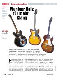
Reference Manual<br />
Fig. 1.1 <strong>Macro</strong>-Tech Amplifier<br />
1.2 Features<br />
<strong>Macro</strong>-Tech amplifiers use cutting edge technology to<br />
deliver the ultimate in power and value for their size,<br />
weight and price. They offer numerous advantages over<br />
conventional designs and provide benefits you can’t get<br />
in amplifiers from any other manufacturer.<br />
Here are some of their many features:<br />
❏ Crown’s Grounded Bridge design delivers large voltage<br />
swings without using easily stressed output-transistor configurations<br />
like conventional amplifiers. The results are<br />
lower distortion and superior reliability.<br />
❏ Patented ODEP (Output Device Emulation Protection) circuitry<br />
compensates for overheating and overload to keep<br />
the amplifier working when others would fail.<br />
❏ IOC ® (Input/Output Comparator) circuitry immediately<br />
alerts of any distortion exceeding 0.05%, providing dynamic<br />
proof of distortion-free performance.<br />
❏ PIP (Programmable Input Processor) connector accepts<br />
accessories that tailor the amplifier to suit specific applications.<br />
❏ Enhanced PIP2 (Programmable Input Processor)<br />
connector accepts new accessory modules that further<br />
tailor the amplifier to suit specific applications,<br />
including wideband load current monitoring.<br />
❏ Two mono modes (Bridge-Mono and Parallel-Mono) for<br />
driving a wide range of load impedances.<br />
❏ Very low harmonic and intermodulation distortion result in<br />
the best dynamic transfer function in the industry.<br />
❏ High damping factor provides superior control over lowfrequency<br />
drivers for a clean, accurate low end.<br />
❏ Full protection against shorted outputs, mismatched<br />
loads, input/output DC, general overheating, high-frequency<br />
overloads and internal faults.<br />
❏ Dedicated power supply transformers isolate channels in<br />
Stereo mode for superb crosstalk characteristics and reliability—each<br />
channel is virtually a separate amplifier.<br />
❏ Balanced inputs with internal three-position sensitivity<br />
Page 7
switch and adjustable front-panel level controls.<br />
❏ Versatile 5-way binding posts make it easy to connect<br />
output wiring.<br />
❏ Full protection from shorted, open and mismatched<br />
loads, general overheating. DC, high-frequency overloads,<br />
and full internal fault protection are provided by<br />
our latest protection scheme: “Quad-Mute.”<br />
❏ Efficient heat sinks and a self-contained forced-air cooling<br />
system dissipate heat quickly and evenly for extra<br />
amplifier protection and greater power output.<br />
<strong>Macro</strong>-Tech ® <strong>602</strong>/<strong>1202</strong>/<strong>2402</strong> Power Amplifiers<br />
❏ Extra rugged, extruded aluminum front panel with ODEP<br />
and signal presence/IOC indicators for each channel,<br />
and an Enable indicator.<br />
❏ Mounts in a standard 19-inch (48.3-cm) equipment rack<br />
(units can also be stacked).<br />
❏ Three-Year, No-Fault, Full warranty completely protects<br />
your investment and guarantees its specifications.<br />
Page 8 Reference Manual
<strong>Macro</strong>-Tech ® <strong>602</strong>/<strong>1202</strong>/<strong>2402</strong> Power Amplifiers<br />
2 Controls, Indicators &<br />
Connectors<br />
A. Dust Filters<br />
The dust filters remove large particles from the air drawn<br />
in by the cooling fan. Check the filters regularly to prevent<br />
clogging. The filter elements can be easily removed<br />
for cleaning by gently pulling them away from<br />
the front panel (see Sections 3.2 and 4.5).<br />
B. Level Controls<br />
The output level for each channel is set with these convenient<br />
level controls mounted on the front panel. Each<br />
level control has 31 detents for precise adjustment (see<br />
Section 4.4). A security option is available to prevent<br />
tampering (see Section 8.3).<br />
C. Signal/IOC Indicators<br />
These green multifunction indicators show signal presence<br />
and distortion for each channel. As signal presence<br />
indicators, they flash synchronously with the<br />
output audio signals to show their presence. As IOC<br />
(Input/Output Comparator) indicators, they flash<br />
brightly with a 0.1 second hold delay if there is a difference<br />
of 0.05% or more between the input and output<br />
signal waveforms. This provides proof of distortion-free<br />
performance. Note: The Channel 2 IOC indicator stays<br />
on in Parallel-Mono mode (see Section 4.2).<br />
D. ODEP Indicators<br />
During normal operation of the ODEP (Output Device<br />
Emulation Protection) circuitry, these amber indicators<br />
glow brightly to show the presence of reserve thermaldynamic<br />
energy. They dim proportionally as energy reserves<br />
decrease. In the rare event that energy reserves<br />
Reference Manual<br />
Fig. 2.1 Front Panel Controls & Indicators<br />
are depleted, the indicators turn off and ODEP proportionally<br />
limits output drive so the amplifier can safely<br />
continue operating even under severe conditions.<br />
These indicators can also help identify more unusual<br />
operating conditions (see Section 4.2).<br />
E. Enable Indicator<br />
This indicator lights when the amplifier has been “enabled”<br />
or turned on, and AC power is available (see<br />
Section 4.2).<br />
F. Enable Switch<br />
This push button is used to turn the amplifier on and off.<br />
When turned on, the output is muted for approximately<br />
four seconds to protect your system from start-up transients.<br />
(This delay can be changed. Contact Crown’s<br />
Technical Support Group for details.)<br />
G. Power Cord<br />
The power cord has an appropriate plug for the required<br />
voltage. 120 VAC, 60 Hz North American <strong>Macro</strong>-Tech<br />
<strong>602</strong>s and <strong>1202</strong>s have 14 AWG line cords and NEMA 5-<br />
15P plugs. <strong>Macro</strong>-Tech <strong>2402</strong>s have 12 AWG line cords<br />
and NEMA 5-20P plugs. International units are shipped<br />
with an appropriate line cord and plug. See Section 7<br />
for AC power usage.<br />
H. Stereo/Mono Switch<br />
The three operating modes of a <strong>Macro</strong>-Tech amplifier<br />
are controlled by this switch. Stereo mode is used for<br />
normal two-channel operation, Bridge-Mono mode is<br />
used to drive a single channel with a load impedance of<br />
at least 4 ohms, and Parallel-Mono mode is used to<br />
Page 9
<strong>Macro</strong>-Tech ® <strong>602</strong>/<strong>1202</strong>/<strong>2402</strong> Power Amplifiers<br />
Fig. 2.2 Rear Panel Controls & Connectors<br />
(Note: Reset Switches (Item I) only available on the <strong>Macro</strong>-Tech <strong>2402</strong> model.)<br />
drive a single channel with an impedance less than 4<br />
ohms. Important: Turn off the amplifier before changing<br />
the stereo/mono switch (see Section 3.3).<br />
I. Reset Switches (<strong>Macro</strong>-Tech <strong>2402</strong> only)<br />
The <strong>Macro</strong>-Tech <strong>2402</strong> has a back panel Reset switch<br />
for each channel. Each switch resets the circuit breaker<br />
that protects the channel’s power supply from overload.<br />
J. PIP Module<br />
The standard PIP2-FXQ is included with your amplifier.<br />
It provides female three-pin XLR input connectors. A<br />
variety of other PIP modules can be used in place of the<br />
PIP2-FXQ. They add additional features that customize<br />
the amplifier for different applications (see Section 8.1<br />
for information on available PIP modules).<br />
❑ Input Sensitivity Switch (not shown)<br />
The three-position input sensitivity switch located inside<br />
the amplifier can be set after removing the PIP module<br />
(J). It is set at the factory to 0.775 volts for standard 1kHz<br />
output into 8 ohms. It can also be set to 1.4 volts for<br />
standard 1-kHz output into 8 ohms, or a fixed voltage<br />
gain of 26 dB (see Section 4.4).<br />
K. Balanced Phone Jack Inputs<br />
Balanced 1 /4-inch phone jack input connectors are provided<br />
on the PIP2-FXQ. The phone jacks can be wired<br />
for either balanced (tip, ring and sleeve) or unbalanced<br />
(tip and sleeve) input signals. Caution: The Channel 2<br />
input should NOT be used in either Bridge Mono or<br />
Parallel Mono mode.<br />
L. Balanced XLR Inputs<br />
The factory-installed PIP2-FXQ provides a three-pin female<br />
XLR connector for balanced input to each channel.<br />
The XLR inputs are connected in parallel with the<br />
amplifier’s phone jack inputs. Because the PIP2-FXQ<br />
does not have any active circuitry, its XLR connectors<br />
can also be used as “daisy chain” outputs to connect<br />
signals from phone jack inputs to multiple amplifiers<br />
(see Section 3.3.4). Caution: The Channel 2 input<br />
should NOT be used in either Bridge Mono or Parallel<br />
Mono mode.<br />
M. Output Jacks<br />
A pair of versatile 5-way binding posts is provided for<br />
the output of each channel. The 5-way binding posts<br />
accept banana plugs, spade lugs or bare wire. (European<br />
models do not accept banana plugs.)<br />
N. Input Ground Lift Switch<br />
The input ground lift switch is located on the PIP2-FXQ.<br />
It is used to isolate the input signal grounds from the AC<br />
(chassis) ground to help prevent ground loops that can<br />
result in unwanted hum and noise (see Section 3.3.4 for<br />
more information about preventing ground loops).<br />
Page 10 Reference Manual
<strong>Macro</strong>-Tech ® <strong>602</strong>/<strong>1202</strong>/<strong>2402</strong> Power Amplifiers<br />
3 Installation<br />
3.1 Mounting<br />
<strong>Macro</strong>-Tech amplifiers are designed for standard<br />
19-inch (48.3-cm) rack mounting and “stack” mounting<br />
without a cabinet. For more efficient cooling and extra<br />
support in a rack, it is recommended that units be<br />
stacked directly on top of each other.<br />
Important: If the unit will be transported, it should also<br />
be securely supported at the back of the rack.<br />
16 in<br />
40.6 cm<br />
AIR<br />
FLOW<br />
2 in<br />
(5 cm)<br />
MIN.<br />
Reference Manual<br />
Fig. 3.1 Mounting Dimensions<br />
3.2 Cooling<br />
NEVER block the side or front air vents. <strong>Macro</strong>-Tech<br />
amplifiers do not need to be mounted with space between<br />
them. If you must leave open spaces in a rack for<br />
any reason, close them with blank panels to prevent air<br />
from recycling into the front of other amplifiers. Allow at<br />
least 35 cubic feet (1 cubic meter) per minute per unit<br />
for the <strong>Macro</strong>-Tech <strong>602</strong> and <strong>1202</strong>, and at least 45 cubic<br />
feet (1.3 cubic meters) per minute per unit for the<br />
<strong>Macro</strong>-Tech <strong>2402</strong>. Additional air flow may be required<br />
when driving low impedance loads at consistently high<br />
output levels. Refer to Section 7 for detailed information<br />
on thermal dissipation.<br />
17 in<br />
43.2 cm<br />
IMPORTANT: Be sure rear of amplifier<br />
is securely mounted to rack.<br />
AMPLIFIER<br />
(TOP VIEW)<br />
AIR FLOW<br />
AIR<br />
FLOW<br />
Fig. 3.2 Top View of a Rack-Mounted Unit<br />
RACK<br />
CABINET<br />
When mounting the amplifier in a rack, the side walls of<br />
the rack should be at least 2 inches (5 cm) away from<br />
the chassis as shown in Figure 3.2.<br />
Tip: An easy way to verify adequate cooling is to observe<br />
the ODEP indicators while the amplifier is operating<br />
under worst-case conditions. If the indicators dim,<br />
additional cooling is recommended.<br />
If your rack has a front door that could block air flow to<br />
the amplifier’s air intakes, you must provide adequate<br />
air flow by installing a grille in the door or by pressurizing<br />
the air behind the door. Wire grilles are recommended<br />
over perforated panels because they tend to<br />
cause less air restriction. A good choice for pressurizing<br />
the air behind a rack cabinet door is to mount a<br />
“squirrel cage” blower inside the rack (Option 1 below).<br />
At the bottom of the rack, mount the blower so it blows<br />
outside air into the space between the door and in front<br />
of the amplifiers, pressurizing the “chimney” behind the<br />
door. This blower should not blow air into or take air out<br />
of the space behind the amplifiers. For racks without a<br />
door, you can evacuate the rack by mounting the blower<br />
at the top of the rack so that air inside the cabinet is<br />
drawn out the back (Option 2 below).<br />
AIR<br />
FLOW<br />
AIR<br />
FLOW<br />
BLOWER<br />
(OPTION 1)<br />
BLOWER<br />
(OPTION 2)<br />
EQUIPMENT<br />
RACK<br />
(SIDE VIEW)<br />
FRONT<br />
OF<br />
RACK<br />
DOOR<br />
Fig. 3.3 Proper Air Flow in a Rack Cabinet<br />
If the air supply is unusually dusty, you might want to<br />
pre-filter it using commercial furnace filters to prevent<br />
rapid loading of the unit’s own air filter. When needed,<br />
the unit’s filter can be cleaned with mild dish detergent<br />
and water (see Section 4.5).<br />
Page 11
3.3 Wiring<br />
This section describes the most common ways to install<br />
your amplifier in a sound system. The input and<br />
output terminals are located on the back panel. Please<br />
use care when making connections, selecting signal<br />
sources and controlling the output level. The load you<br />
save may be your own! Crown assumes no liability for<br />
damaged loads resulting from careless amplifier use or<br />
deliberate overpowering.<br />
CAUTION: Always remove power from the unit and<br />
turn the level controls off while making or changing<br />
connections. This is very important when loudspeakers<br />
are connected because it reduces the chance of<br />
loud blasts that can cause loudspeaker damage.<br />
<strong>Macro</strong>-Tech amplifiers may be operated in one of three<br />
modes (Stereo, Bridge-Mono, and Parallel-Mono) by<br />
switching the stereo/mono switch on the back panel.<br />
There are VERY IMPORTANT wiring differences among<br />
these three modes which will be discussed next.<br />
Fig. 3.4 Stereo Wiring<br />
<strong>Macro</strong>-Tech ® <strong>602</strong>/<strong>1202</strong>/<strong>2402</strong> Power Amplifiers<br />
3.3.1 Stereo (Two-Channel) Operation<br />
In Stereo mode, installation is very intuitive: input Channel<br />
1 feeds output Channel 1, and input Channel 2 feeds<br />
output Channel 2. To put the amplifier in Stereo mode,<br />
first turn off the amplifier, then slide the stereo/mono<br />
switch to the center position, and properly connect the<br />
output wiring as shown in Figure 3.4. A pair of 5-way<br />
binding posts is provided for each channel to facilitate<br />
easy connection of loudspeaker wires. Observe correct<br />
loudspeaker polarity and be very careful not to short<br />
the two outputs.<br />
CAUTION: In Stereo mode, never parallel the two<br />
outputs by directly tying them together, and never<br />
parallel them with the output of another amplifier.<br />
Such a connection does not result in increased power<br />
output, but may result in overheating and premature<br />
activation of the protection circuitry.<br />
Note: A method for paralleling multiple amplifiers for failsafe<br />
redundancy is available from Crown’s Technical<br />
Support Group.<br />
Page 12 Reference Manual
<strong>Macro</strong>-Tech ® <strong>602</strong>/<strong>1202</strong>/<strong>2402</strong> Power Amplifiers<br />
3.3.2 Bridge-Mono Operation<br />
Bridge-Mono mode is intended for driving loads with a<br />
total impedance of 4 ohms or more (If the load is less<br />
than 4 ohms, see Section 3.3.3). Installing the amplifier<br />
in Bridge-Mono mode is very different from the other<br />
modes and requires special attention.<br />
To put the amplifier in Bridge-Mono mode, turn the amplifier<br />
off and slide the stereo/mono switch to the right<br />
(as you face the back of the amplifier). Both outputs<br />
receive the signal from Channel 1 with the output of<br />
Channel 2 inverted so it can be bridged with the Channel<br />
1 output. DO NOT USE THE CHANNEL 2 INPUT or<br />
the signal level and quality may be greatly degraded.<br />
Keep the Channel 2 level control turned down completely<br />
(counterclockwise).<br />
Note: The input jack and level control of Channel 2 are<br />
Reference Manual<br />
Fig. 3.5 Bridge-Mono Wiring<br />
not defeated in Bridge-Mono mode. Any signal fed into<br />
Channel 2 will work against and add to or distort the<br />
signal in Channel 1.<br />
Connect the load across the Channel 1 and 2 red binding<br />
posts with the positive lead from the load attaching<br />
to the red post of Channel 1 and the negative lead of the<br />
load attaching to the red post of Channel 2 as shown in<br />
Figure 3.5. THE TWO BLACK BINDING POSTS ARE<br />
NOT USED AND SHOULD NOT BE SHORTED. The<br />
load must be balanced (neither side shorted to ground).<br />
CAUTION: Be certain all equipment (meters,<br />
switches, etc.) connected to the mono output is balanced.<br />
To prevent oscillations, both sides of the line<br />
must be isolated from the input grounds.<br />
Page 13
3.3.3 Parallel-Mono Operation<br />
Parallel-Mono mode is intended for driving loads with a<br />
net impedance of less than 4 ohms. (See Bridge-Mono<br />
if the load is 4 ohms or greater.) Installing the amp in<br />
Parallel-Mono mode is very different from the other<br />
modes and requires special attention.<br />
CAUTION: Do not attempt to operate in Stereo or<br />
Bridge-Mono mode until the Parallel-Mono jumper<br />
is first removed. Failure to do so will result in high<br />
distortion and excessive heating.<br />
To put the amplifier in Parallel-Mono mode, turn it off<br />
and slide the stereo/mono switch to the left (as you face<br />
the back panel). Connect the input signal to Channel 1<br />
only. The Channel 2 input and level control are by-<br />
Fig. 3.6 Parallel-Mono Wiring<br />
<strong>Macro</strong>-Tech ® <strong>602</strong>/<strong>1202</strong>/<strong>2402</strong> Power Amplifiers<br />
passed in this mode, so they should not be used.<br />
Note: It is normal for the IOC indicator of Channel 2 to<br />
remain lit in Parallel-Mono mode.<br />
Install a jumper wire between the red binding posts of<br />
both Channel 1 and 2 that is at least 14 gauge in size.<br />
Then, connect the load to the output of Channel 1 as<br />
shown in Figure 3.6. The positive lead from the load<br />
connects to the red binding post of Channel 1 and the<br />
negative lead from the load connects to the black binding<br />
post of Channel 1.<br />
CAUTION: Remove the jumper wire before changing<br />
to Stereo or Bridge-Mono mode.<br />
Page 14 Reference Manual
<strong>Macro</strong>-Tech ® <strong>602</strong>/<strong>1202</strong>/<strong>2402</strong> Power Amplifiers<br />
3.3.4 Input Connection<br />
Both the balanced XLR and phone jack inputs have a<br />
nominal impedance of 20 k ohms (10 k ohms with unbalanced<br />
wiring) and will accept the line-level output of<br />
most devices. Female three-pin XLR input connectors<br />
and 1 /4-inch jacks are provided on the standard<br />
PIP2-FXQ input module (other PIP modules are described<br />
in Section 8.1). Correct input wiring will depend<br />
on two factors: (1) whether the input signals are balanced<br />
or unbalanced, and (2) whether the signal source<br />
Reference Manual<br />
Fig. 3.7 Unbalanced Input Wiring<br />
Fig. 3.8 Balanced Input Wiring<br />
floats or has a ground reference. Figures 3.7 and 3.8<br />
show the recommended connection techniques for<br />
each type of signal source.<br />
The amplifier’s built-in 1 /4-inch phone jack input connectors<br />
can be wired similarly for balanced or unbalanced,<br />
floating or ground-referenced sources. They have a<br />
standard tip-ring-sleeve (TRS) configuration: the tip is<br />
positive (+), the ring is negative (–) and the sleeve is<br />
chassis (see Figure 3.9). Wiring for various sources follows<br />
the XLR wiring guidelines shown in Figures 3.7<br />
and 3.8.<br />
Fig. 3.9 Balanced and Unbalanced Phone Plugs<br />
Page 15
dB<br />
Please follow the instruction in Section 3.3.2 and 3.3.3 if<br />
the amplifier will be used in either Bridge-Mono or Parallel-Mono<br />
mode. Remember, do not use the Channel 2<br />
input in either of these mono modes.<br />
SOLVING INPUT PROBLEMS<br />
Sometimes large infrasonic (subaudible) frequencies<br />
are present in the input signal. These can damage loudspeakers<br />
by overloading or overheating them. To at-<br />
0<br />
–5<br />
–10<br />
–15<br />
1 µ F<br />
.1 µ F<br />
.05 µ F<br />
.01 µ F<br />
1 Hz 10 Hz 100 Hz 1 kHz 10 kHz<br />
Frequency<br />
Fig. 3.10 Infrasonic Filter Capacitors<br />
tenuate such frequencies, place a capacitor in series<br />
with the input signal line. The graph in Figure 3.10<br />
shows some capacitor values and how they affect the<br />
frequency response. Use only low-leakage paper, mylar<br />
or tantalum capacitors.<br />
Another problem to avoid is the presence of large levels<br />
of radio frequencies or RF in the input signal. Although<br />
high RF levels may not pose a threat to the<br />
amplifier, they can burn out tweeters or other loads that<br />
are sensitive to high frequencies. Extremely high RF levels<br />
can also cause your amplifier to prematurely activate<br />
its protection circuitry, resulting in inefficient<br />
1.8 K ohm<br />
.003<br />
Source<br />
µ F<br />
R 600 ohm<br />
Source<br />
A<br />
3.9 mH<br />
B<br />
.015<br />
µ F<br />
To<br />
Amp<br />
GND<br />
To<br />
Amp<br />
GND<br />
12 dB/octave<br />
C<br />
6 dB/octave<br />
5 mH<br />
To<br />
–20<br />
R 600 ohm<br />
Source<br />
C<br />
.018<br />
µ F<br />
Amp<br />
GND<br />
4 kHz 10 kHz 40 kHz 100 kHz<br />
Note: A low source impedance (R) can be<br />
increased to 600 ohms with an appropriate resistor.<br />
Frequency<br />
Fig. 3.11 Unbalanced RFI Filters<br />
operation. RF can be introduced into the signal by local<br />
radio stations and from the bias signal of many tape<br />
recorders. To prevent high levels of input RF, install an<br />
appropriate low-pass filter in series with the the input<br />
B<br />
A<br />
dB<br />
0<br />
–10<br />
<strong>Macro</strong>-Tech ® <strong>602</strong>/<strong>1202</strong>/<strong>2402</strong> Power Amplifiers<br />
Balanced In<br />
Input Wiring Tips<br />
1. Use only shielded cable. Cables with<br />
higher density shields are better. Spiral<br />
wrapped shield is not recommended.<br />
2. When using unbalanced lines, keep the<br />
cables as short as possible. Avoid cable<br />
lengths greater than 10 feet (3 meters).<br />
3. Do not run signal cables together with<br />
high-level wiring such as loudspeaker wires<br />
or AC cords. This greatly lessens the chance<br />
of hum or noise being induced into the input<br />
cables.<br />
4. Turn the entire system off before changing<br />
connections. Turn level controls down<br />
completely before powering the system back<br />
up. Crown is not liable for damage incurred<br />
when any transducer or component is<br />
overdriven.<br />
Page 16 Reference Manual<br />
A<br />
B<br />
C<br />
D<br />
+<br />
–<br />
910 Ω<br />
910 Ω<br />
.003<br />
µ F<br />
1.8 mH<br />
+<br />
+<br />
Balanced In<br />
.015<br />
µ F<br />
Balanced Out<br />
–<br />
1.8 mH<br />
–<br />
2.5 mH<br />
+<br />
+<br />
Balanced In<br />
.018<br />
µ F<br />
Balanced Out<br />
–<br />
2.5 mH<br />
–<br />
0.47 Film 1.8 mH<br />
+<br />
+<br />
Balanced In<br />
.015<br />
µ F<br />
Balanced Out<br />
–<br />
0.47 Film 1.8 mH<br />
–<br />
+<br />
Balanced Out<br />
Fig. 3.12 Balanced RFI Filters<br />
signal. Some examples of unbalanced wiring for lowpass<br />
filters are shown in Figure 3.11.<br />
For balanced input wiring use one of the examples in<br />
Figure 3.12. Filters A, B and C correspond to the unbalanced<br />
filters above. Filter D also incorporates the infrasonic<br />
filter described previously.<br />
A third problem to avoid is hum. The two most common<br />
sources of hum in an audio system are inductive coupling<br />
and ground loops.<br />
Inductive coupling can occur when input cables are<br />
–
<strong>Macro</strong>-Tech ® <strong>602</strong>/<strong>1202</strong>/<strong>2402</strong> Power Amplifiers<br />
subjected to a magnetic field from a power cord or<br />
power transformer. One way to prevent inductive coupling<br />
is to lace the input cables together along their<br />
length and route them as far away as possible from<br />
power transformers and power cords. The use of<br />
shielded pair cable is another effective way to reduce<br />
or eliminate hum resulting from inductive coupling.<br />
Input and output grounds are sometimes tied together<br />
for testing or metering. This can cause feedback oscillation<br />
from load current in the test loop. In some systems,<br />
even the AC power line may provide this<br />
feedback path. Proper grounding, input isolation and<br />
isolation of common AC devices in the system is good<br />
practice.<br />
Use Good Output Connectors<br />
1. To prevent possible shorts, do not expose<br />
the loudspeaker cable connectors.<br />
2. Do not use connectors that might accidentally<br />
tie two channels together when making<br />
or breaking connections (for example, a<br />
standard three-wire stereo phone plug).<br />
3. Connectors that can be plugged into AC<br />
power receptacles should never be used.<br />
4. Connectors with low current-carrying capacity<br />
should not be used.<br />
5. Connectors with any tendency to short<br />
should never be used.<br />
3.3.5 Output Connection<br />
Consider the power-handling capacity of your load before<br />
connecting it to the amplifier. Crown is not liable for<br />
damage incurred at any time due to overpowering. Fusing<br />
loudspeaker lines is highly recommended (see Section<br />
3.3.6). Also, please pay close attention to the<br />
precautions provided in Section 4.1.<br />
HOW TO DETERMINE<br />
APPROPRIATE WIRE GAUGE<br />
It is important to use loudspeaker cables with sufficient<br />
Reference Manual<br />
gauge (thickness) for the length being used. The resistance<br />
introduced by inadequate loudspeaker cables<br />
will reduce both the output power and the motion con-<br />
40<br />
30<br />
20<br />
15<br />
10<br />
9<br />
8<br />
7<br />
6<br />
5<br />
4<br />
3<br />
2<br />
1.5<br />
1<br />
0.9<br />
0.8<br />
0.7<br />
0.6<br />
0.5<br />
R L<br />
LOAD<br />
RESISTANCE<br />
(ohms)<br />
R L<br />
R S<br />
DAMPING<br />
FACTOR<br />
20,000<br />
10,000<br />
5,000<br />
2,000<br />
1,000<br />
500<br />
200<br />
100<br />
50<br />
20<br />
10<br />
5<br />
2<br />
1<br />
.0002 R S<br />
SOURCE<br />
RESISTANCE<br />
(ohms)<br />
.0004<br />
.0006<br />
.001<br />
.002<br />
.004<br />
.006<br />
.01<br />
.02<br />
.04<br />
.06<br />
.1<br />
.2<br />
.4<br />
.6<br />
1<br />
2<br />
4<br />
6<br />
10<br />
20<br />
40<br />
2-COND.<br />
CABLE<br />
(feet)<br />
1<br />
2<br />
5<br />
10<br />
20<br />
50<br />
100<br />
200<br />
500<br />
1000<br />
2000<br />
5000<br />
8000<br />
5000<br />
(ohms/1000 ft.)<br />
Example Shown:<br />
R L = 8 ohms; R S = 0.016 ohms or D.F. = 500;<br />
Cable Length = 10 ft.; answer: #8 wire<br />
Fig. 3.13 Wire Size Nomograph<br />
1000<br />
500<br />
100<br />
50<br />
10<br />
5<br />
1<br />
.5<br />
.1<br />
.05<br />
.01<br />
COPPER<br />
WIRE<br />
(AWG)<br />
#28<br />
#26<br />
#24<br />
#22<br />
#20<br />
#18<br />
#16<br />
#14<br />
#12<br />
#10<br />
#8<br />
#6<br />
#4<br />
#2<br />
#0<br />
#00<br />
#0000<br />
Page 17
trol of the loudspeakers. The latter problem occurs because<br />
the damping factor decreases as the cable resistance<br />
increases. This is very important because the<br />
amplifier’s excellent damping factor can easily be negated<br />
by insufficient loudspeaker cables.<br />
Use the nomograph in Figure 3.13 and the procedure<br />
that follows to find the recommended wire gauge (AWG<br />
or American Wire Gauge) for your system.<br />
1. Note the load resistance of the loudspeakers connected<br />
to each channel of the amplifier. Mark this value on the<br />
“Load Resistance” line of the nomograph.<br />
2. Select an acceptable damping factor and mark it on the<br />
“Damping Factor” line. Your amplifier can provide an excellent<br />
damping factor of 1,000 from 10 to 400 Hz in Stereo<br />
mode with an 8-ohm load. In contrast, typical damping factors<br />
are 50 or lower. Higher damping factors yield lower distortion<br />
and greater motion control over the loudspeakers. A<br />
common damping factor for commercial applications is between<br />
50 and 100. Higher damping factors may be desirable<br />
for live sound, but long cable lengths often limit the<br />
highest damping factor that can be achieved practically.<br />
(Under these circumstances, Crown’s IQ System ® is often<br />
used so amplifiers can be monitored and controlled when<br />
they are located very near the loudspeakers.) In recording<br />
studios and home hi-fi, a damping factor of 500 or more is<br />
very desirable.<br />
3. Draw a line through the two points with a pencil, and<br />
continue until it intersects the “Source Resistance” line.<br />
4. On the “2-Cond. Cable” line, mark the length of the<br />
cable run.<br />
5. Draw a pencil line from the mark on the “Source Resistance”<br />
line through the mark on the “2-Cond. Cable” line,<br />
and on to intersect the “Annealed Copper Wire” line.<br />
6. The required wire gauge for the selected wire length and<br />
damping factor is the value on the “Annealed Copper Wire”<br />
line. Note: Wire size increases as the AWG gets smaller.<br />
7. If the size of the cable exceeds what you want to use,<br />
(1) find a way to use shorter cables, like using the IQ System,<br />
(2) settle for a lower damping factor, or (3) use more<br />
than one cable for each line. Options 1 and 2 will require the<br />
substitution of new values for cable length or damping factor<br />
in the nomograph. For option 3, estimate the effective wire<br />
gauge by subtracting 3 from the apparent wire gauge every<br />
time the number of conductors of equal gauge is doubled.<br />
So, if #10 wire is too large, two #13 wires can be substituted,<br />
or four #16 wires can be used for the same effect.<br />
SOLVING OUTPUT PROBLEMS<br />
Sometimes high-frequency oscillations occur which<br />
can cause your amplifier to prematurely activate its protection<br />
circuitry and result in inefficient operation. The<br />
effects of this problem are similar to the effects of the RF<br />
<strong>Macro</strong>-Tech ® <strong>602</strong>/<strong>1202</strong>/<strong>2402</strong> Power Amplifiers<br />
problem described in Section 3.3.4. To prevent highfrequency<br />
oscillations:<br />
1. Lace together the loudspeaker conductors for<br />
each channel; do not lace together the conductors<br />
from different channels. This minimizes the<br />
chance that cables will act like antennas and<br />
transmit or receive high frequencies that can<br />
cause oscillation.<br />
2. Avoid using shielded loudspeaker cable.<br />
3. Avoid long cable runs where the loudspeaker<br />
cables from different amplifiers share a common<br />
cable tray or cable jacket.<br />
4. Never connect the amplifier’s input and output<br />
grounds together.<br />
5. Never tie the outputs of multiple amplifiers together.<br />
6. Keep loudspeaker cables well separated from<br />
input cables.<br />
7. Install a low-pass filter on each input line (similar<br />
to the RF filters described in Section 3.3.4).<br />
8. Install input wiring according to the instructions<br />
in Section 3.3.4.<br />
Another problem to avoid is the presence of large subsonic<br />
currents when primarily inductive loads are<br />
used. Examples of inductive loads are 70-volt transformers<br />
and electrostatic loudspeakers.<br />
Inductive loads can appear as a short circuit at low frequencies.<br />
This can cause the amplifier to produce large<br />
low-frequency currents and activate its protection circuitry.<br />
Always take the precaution of installing a highpass<br />
filter in series with the amplifier’s input when<br />
inductive loads are used. A 3-pole, 18-dB-per-octave<br />
filter with a –3 dB frequency of 50 Hz is recommended<br />
(depending on the application, an even higher –3 dB<br />
frequency may be desirable). Such a filter is described<br />
with infrasonic frequency problems in Section 3.3.4.<br />
4-ohm, 20-watt<br />
Resistor<br />
590 to 708 µF Capacitor<br />
120 VAC, N.P.<br />
Fig. 3.14 Inductive Load (Transformer) Network<br />
Page 18 Reference Manual<br />
+<br />
From<br />
Amplifier<br />
Output<br />
–<br />
+<br />
–<br />
Inductive<br />
Load
<strong>Macro</strong>-Tech ® <strong>602</strong>/<strong>1202</strong>/<strong>2402</strong> Power Amplifiers<br />
Another way to prevent the amplifier from prematurely<br />
activating its protection systems and to protect inductive<br />
loads from large low-frequency currents is to connect<br />
a 590 to 708 µF nonpolarized capacitor and 4-ohm,<br />
20-watt resistor in series with the amplifier’s output and<br />
the positive (+) lead of the transformer. The circuit<br />
shown in Figure 3.14 uses components that are available<br />
from most electronic supply stores.<br />
3.3.6 Additional Load Protection<br />
<strong>Macro</strong>-Tech amplifiers generate enormous power. If<br />
your loudspeakers do not have built-in protection from<br />
excessive power, it’s a good idea to protect them. Loudspeakers<br />
are subject to thermal damage from sustained<br />
overpowering and mechanical damage from large transient<br />
voltages. Special fuses can be used to protect<br />
your loudspeakers in both cases.<br />
Fig. 3.15 Loudspeaker Fuse Nomograph<br />
Reference Manual<br />
Two different types of fuses are required for thermal protection<br />
and voltage protection. Slow-blow fuses are usually<br />
selected to protect loudspeakers from thermal<br />
damage because they are similar to loudspeakers in<br />
the way they respond to thermal conditions over time. In<br />
contrast, high-speed instrument fuses like the Littlefuse<br />
361000 series are used to protect loudspeakers from<br />
large transient voltages. The nomograph in Figure 3.15<br />
can be used to select the properly rated fuse for either<br />
type of loudspeaker protection.<br />
There are basically two approaches that can be taken<br />
when installing fuses for loudspeaker protection. A common<br />
approach is to put a single fuse in series with the<br />
output of each channel. This makes installation convenient<br />
because there is only one fuse protecting the loads<br />
on each output. The main disadvantage of this approach<br />
becomes obvious if the fuse blows because none of the<br />
loads will receive any power.<br />
A better approach is to fuse each driver independently.<br />
This allows you to apply the most appropriate protection<br />
for the type of driver being used. In general, lowfrequency<br />
drivers (woofers) are most susceptible to<br />
thermal damage and high-frequency drivers (tweeters)<br />
are usually damaged by large transient voltages. This<br />
means that your loudspeakers will tend to have better<br />
protection when the woofers are protected by slow-blow<br />
fuses and high-frequency drivers are protected by highspeed<br />
instrument fuses.<br />
3.4 AC Power Requirements<br />
All <strong>Macro</strong>-Tech amplifiers are shipped with an appropriate<br />
line cord. When possible, use a power receptacle<br />
on a dedicated circuit and always make sure that it can<br />
supply the correct voltage and current. We do not recommend<br />
operating your amplifier on voltages greater<br />
than 10% above or below the unit’s rated voltage. For<br />
example, if your amplifer is rated for 120 VAC, the line<br />
voltage should not exceed 132 VAC. See Section 7 for<br />
power requirements under a variety of conditions.<br />
All specifications in this manual were measured using<br />
120 VAC, 60 Hz power, unless otherwise noted. Specifications<br />
were derived using a voltage that is accurate to<br />
within 0.5% with THD less than 1.0% under all testing<br />
conditions. Performance variations can occur at other<br />
AC voltages and frequencies. In addition, line regulation<br />
problems directly affect the output power from the<br />
amplifier.<br />
Page 19
4 Operation<br />
4.1 Precautions<br />
<strong>Macro</strong>-Tech amplifiers are protected from internal and<br />
external faults, but you should still take the follow precautions<br />
for optimum performance and safety:<br />
1. Improper wiring for Stereo, Bridge-Mono and<br />
Parallel-Mono modes can result in serious operating<br />
difficulties. Refer to Section 3.3 for details.<br />
2. WARNING: Do not change the position of the<br />
stereo/mono switch unless the amplifier is first<br />
turned off.<br />
3. CAUTION: In Parallel-Mono mode, a jumper is<br />
used between the red (+) Channel 1 and 2 output<br />
binding posts. Be sure to remove this jumper for<br />
Stereo or Bridge-Mono mode, otherwise high<br />
distortion and excessive heating will definitely<br />
occur. Check the stereo/mono switch on the back<br />
panel for proper position.<br />
4. Turn off the amplifier and unplug it from the AC<br />
mains before removing the PIP module.<br />
5. Use care when making connections, selecting signal<br />
sources and controlling the output level. The<br />
load you save may be your own.<br />
6. Do not short the ground lead of an output cable to<br />
the input signal ground. This may form a ground<br />
loop and cause oscillations.<br />
7. Operate the amplifier from AC mains of not more<br />
than 10% variation above or below the selected line<br />
voltage and only the specified line frequency.<br />
8. Never connect the output to a power supply output,<br />
battery or power main. Such connections may<br />
result in electrical shock.<br />
9. Tampering with the circuitry by unqualified personnel,<br />
or making unauthorized circuit changes invalidates<br />
the warranty.<br />
Remember: Crown is not liable for damage that results<br />
from overdriving other system components.<br />
4.2 Indicators<br />
The amber Enable indicator is provided to show that<br />
the amplifier has been turned on (or enabled), and that<br />
its low-voltage power supply and forced-air cooling system<br />
are working. It does not indicate the status of the<br />
high-voltage power supplies. For example, the Enable<br />
indicator will remain lit during unusual conditions that<br />
would cause the amplifier’s protection systems to put a<br />
<strong>Macro</strong>-Tech ® <strong>602</strong>/<strong>1202</strong>/<strong>2402</strong> Power Amplifiers<br />
Fig. 4.1 Indicators<br />
high-voltage power supply in “standby” mode (see Section<br />
4.3.2).<br />
The amber ODEP indicators confirm the normal operation<br />
of Crown’s patented Output Device Emulation<br />
Protection circuitry. During normal operation, they glow<br />
brightly to show the presence of reserve thermal-dynamic<br />
energy. They dim proportionally as the energy<br />
reserve decreases. In the rare event that there is no reserve,<br />
the indicators turn off and ODEP proportionally<br />
limits the drive level of the output stages so the amplifier<br />
can continue safe operation even when conditions<br />
are severe. (For a more detailed description of ODEP,<br />
see Section 4.3.1.)<br />
The ODEP indicator for the affected channel will turn off<br />
if a high-voltage power supply is put in “standby” mode,<br />
a high-voltage power supply fuse (or breaker) blows, or<br />
a transformer activates its thermal protection circuitry<br />
(see Section 4.3.2). Both ODEP indicators turn off if the<br />
amplifier loses AC power, the power switch is turned off<br />
or the low-voltage power supply fuse blows.<br />
The green Signal/IOC indicators show signal presence<br />
and distortion. As signal presence indicators, they flash<br />
with normal intensity in sync with the output audio signals.<br />
As IOC (Input/Output Comparator) indicators, they<br />
flash brightly if there is any difference between the input<br />
and output signal waveforms greater than 0.05%. Because<br />
transient distortion happens quickly, a 0.1 second<br />
“hold delay” keeps the indicators on long enough<br />
to be easily noticed. The IOC function essentially provides<br />
proof of distortion-free performance. Note: The<br />
Channel 2 IOC indicator will remain lit when running in<br />
Parallel-Mono mode.<br />
Under conditions where one of the amplifier’s high-voltage<br />
power supplies is temporarily put in standby mode,<br />
the Signal/IOC indicators will stay on with full brightness.<br />
They will resume normal operation when the amplifier<br />
is no longer in standby mode.<br />
Note: See Figure 4.2 for an explanation of the conditions<br />
that may activate standby mode.<br />
Page 20 Reference Manual
<strong>Macro</strong>-Tech ® <strong>602</strong>/<strong>1202</strong>/<strong>2402</strong> Power Amplifiers<br />
The table in Figure 4.2 shows the possible states for the<br />
ODEP and Signal/IOC indicators. It also describes the<br />
conditions that may be associated with the different indicator<br />
states. The Enable indicator will be off with the<br />
first indicator state, “There is no power to the amplifier.”<br />
All other conditions in the table will occur with the En-<br />
Reference Manual<br />
Fig. 4.2 <strong>Macro</strong>-Tech ODEP and Signal/IOC Indicator States<br />
able indicator turned on. It is important to note the possible<br />
states of the indicators in the rare event that you<br />
experience a problem. This can greatly aid in determining<br />
the source of problems. Please contact your local<br />
Crown representative or our Technical Support<br />
Group for futher assistance.<br />
Page 21
4.3 Protection Systems<br />
<strong>Macro</strong>-Tech amplifiers provide extensive protection and<br />
diagnostics capabilities. Protection systems include<br />
ODEP, “standby” mode, fuses (or breakers), and special<br />
thermal protection for the unit’s transformers.<br />
4.3.1 ODEP<br />
Crown invented ODEP to solve two long-standing problems<br />
in amplifier design: to prevent amplifier shutdown<br />
during demanding operation and to increase the efficiency<br />
of the output circuitry.<br />
To do this, Crown established a rigorous program to<br />
measure the safe operating area (SOA) of each output<br />
transistor before installing it in an amplifier. Next, Crown<br />
designed intelligent circuitry to simulate the instantaneous<br />
operating conditions of those output transistors.<br />
Its name describes what it does: Output Device Emulation<br />
Protection or ODEP. In addition to simulating the<br />
operating conditions of the output transistors, it also<br />
compares their operation to their known SOA. If it sees<br />
that more power is about to be asked of them than they<br />
are capable of delivering under the present conditions,<br />
ODEP immediately limits the drive level until it falls within<br />
the SOA. Limiting is proportional and kept to an absolute<br />
minimum—only what is required to prevent output<br />
transistor damage.<br />
This level of protection enables Crown to increase output<br />
efficiency to never-before-achieved levels while<br />
greatly increasing amplifier reliability.<br />
The on-board intelligence is monitored in two ways.<br />
First, the front panel ODEP indicators show whether the<br />
amplifier is functioning correctly or if ODEP is limiting<br />
the drive level. Second, ODEP data is fed to the back<br />
panel PIP connector so advanced PIP modules like the<br />
IQ-PIP-USP2 can use it to monitor and control the amplifier.<br />
With ODEP, the show keeps going because you get the<br />
maximum power with the maximum protection.<br />
4.3.2 Standby Mode<br />
An important part of a <strong>Macro</strong>-Tech amplifier's protection<br />
systems is standby mode. Standby protects the<br />
amplifier during potentially catastrophic conditions. It<br />
temporarily removes bias in all four output stages, protecting<br />
the amplifier and its loads. This advanced protection<br />
implementation, called "Quad-Mute," is new to<br />
the <strong>Macro</strong>-Tech series amplifiers. Standby mode can<br />
be identified using the indicator table in Figure 4.2.<br />
Standby mode can be activated in several situations.<br />
First, if dangerous subsonic frequencies or direct cur-<br />
<strong>Macro</strong>-Tech ® <strong>602</strong>/<strong>1202</strong>/<strong>2402</strong> Power Amplifiers<br />
rent (DC) is detected in the amplifier’s output, the unit<br />
will activate its DC/low-frequency protection circuitry<br />
and put the affected channels in standby. This protects<br />
the loads and prevent oscillations. The unit resumes normal<br />
operation as soon as the amplifier no longer detects<br />
dangerous low frequency or DC output. Although<br />
it is extremely unlikely that you will ever activate the<br />
amplifier’s DC/low-frequency protection system, improper<br />
source materials such as subsonic square<br />
waves or input overloads that result in excessively<br />
clipped input signals can activate this system.<br />
The amplifier’s fault protection system will put an amplifier<br />
channel in standby mode in rare situations where<br />
heavy common-mode current is detected in the<br />
channel’s output. The amplifier should never output<br />
heavy common-mode current unless its circuitry is damaged<br />
in some way, and putting a channel in standby<br />
mode helps to prevent further damage.<br />
The amplifier’s transformer thermal protection circuitry<br />
is activated in very unusual circumstances where<br />
the unit’s transformer temperature rises to unsafe levels.<br />
Under these abnormal conditions, the amplifier will<br />
put the channel of the affected transformer in standby<br />
mode. The amplifier will return to normal operation after<br />
the transformer cools to a safe temperature. (For more<br />
information on transformer thermal protection, refer to<br />
the following section.)<br />
An IQ-PIP module may also temporarily place the<br />
amplfier in standby mode, typically for power conservation.<br />
The standby mode status can be triggered either<br />
manually or through IQ's “auto standby” feature. If<br />
triggered via the IQ auto standby feature, the standby<br />
status will be automatically cancelled when the defined<br />
level of input signal is detected. However, if the standby<br />
status has been triggered manually, this status must be<br />
manually cancelled using IQ.<br />
4.3.3 Transformer Thermal Protection<br />
All <strong>Macro</strong>-Tech amplifiers have transformer thermal protection.<br />
It protects the power supplies from damage under<br />
the rare conditions of transformer temperatures<br />
rising too high. A thermal switch embedded in each<br />
transformer removes power to the channel if there is<br />
excessive heat. The switch automatically resets when<br />
the transformer cools to a safe temperature.<br />
It is extremely unlikely that you will ever see a<br />
<strong>Macro</strong>-Tech amplifier activate transformer thermal protection<br />
as long as it is operated within rated conditions<br />
(see Section 6, Specifications). One reason is that<br />
ODEP keeps the amplifier working under very severe<br />
conditions. Even so, higher than rated output levels, ex-<br />
Page 22 Reference Manual
<strong>Macro</strong>-Tech ® <strong>602</strong>/<strong>1202</strong>/<strong>2402</strong> Power Amplifiers<br />
cessively low impedance loads and unreasonably high<br />
input signals can generate more heat in the transformer<br />
than in the output devices. These conditions can overheat<br />
the transformer and activate its protection system.<br />
<strong>Macro</strong>-Tech amplifiers are designed to keep working<br />
under conditions where other amplifiers would fail. But<br />
even when the limits of a <strong>Macro</strong>-Tech amplifier are exceeded,<br />
it will still protect itself—and your investment—<br />
from damage.<br />
4.3.4 Fuses and Circuit Breakers<br />
The power supplies of the <strong>Macro</strong>-Tech <strong>602</strong> and <strong>1202</strong><br />
are protected by fuses. The power supplies of the<br />
<strong>Macro</strong>-Tech <strong>2402</strong> are protected by circuit breakers. With<br />
rated loads and output levels, the fuses (or circuit breakers)<br />
should only shut down the amplifier in the rare instance<br />
of a catastrophic failure. Other protection<br />
systems like ODEP keep the amplifier operational under<br />
most other severe conditions. The fuses (or circuit<br />
breakers) can also shut down the amplifier in cases<br />
where extremely low-impedance loads and high output<br />
levels result in current draw that exceeds their rating.<br />
Again, this should only be possible when operating outside<br />
rated conditions, such as when the amplifier is<br />
used to drive a 1-ohm load in Stereo mode, or when a<br />
signal overloads the input and is clipped severely.<br />
All 120 VAC, 60 Hz units and all <strong>Macro</strong>-Tech <strong>2402</strong>s have<br />
a separate fuse for the low-voltage power supply. All<br />
units have separate fuses or breakers for the high-voltage<br />
power supplies.<br />
<strong>Macro</strong>-Tech amplifiers do not blow their fuses or trip<br />
their breakers unless something is wrong. In the rare<br />
event that an internal fuse blows, please refer the unit to<br />
a qualified technician. If a breaker in a <strong>Macro</strong>-Tech <strong>2402</strong><br />
trips, try to identify and correct the problem before resetting<br />
the breakers with the back panel Reset<br />
switches. If the problem persists, refer the unit to a<br />
qualified technician.<br />
4.4 Controls<br />
The Enable switch is located on the front panel so you<br />
can easily turn the amplifier on and off. If you ever need<br />
to make any wiring or installation changes, don’t forget<br />
to disconnect the power cord. The six steps listed next<br />
should be followed whenever you turn on the amplifier:<br />
1. Turn down the level of your audio source. For<br />
example, set your master mixer’s volume to –∞.<br />
2. Turn down the level controls of the amplifier (if they<br />
are not already down).<br />
3. Turn on the Enable switch. The Enable indicator<br />
Reference Manual<br />
beside the switch should glow. During the four<br />
second mute delay which immediately follows, the<br />
Signal/IOC indicators will flash unpredictably and<br />
the ODEP LEDs will stay off. After the mute delay,<br />
the ODEP indicators should come on with full<br />
brilliance and the Signal/IOC indicators should<br />
function normally (remain off if no signal is present;<br />
flash if a signal is present). Remember, the Channel<br />
2 Signal/IOC indicator will remain on if the amplifier<br />
is in Parallel-Mono mode.<br />
4. After the mute delay, turn up the level of your audio<br />
source to the maximum desired level.<br />
5. Turn up the level controls of the amplifier until the<br />
maximum desired sound level is achieved.<br />
6. Turn down the level of your audio source to its<br />
normal range.<br />
For ease of use, the level controls are also located on<br />
the front panel. Each control has 31 detents for accurate<br />
repeatability. To prevent tampering with these controls,<br />
the Level Control Security Kit is available (see<br />
Section 8.3). Note: In Bridge-Mono and Parallel-Mono<br />
modes, turn down the Channel 2 level control and only<br />
use the Channel 1 control.<br />
The input sensitivity switch is located inside the back<br />
panel of the amplifier. It is factory-set to 0.775 volts for<br />
standard 1-kHz power into 8 ohms. It can be switched<br />
either to 1.4 volts for standard 1-kHz power output, or to<br />
a fixed voltage gain of 26 dB. When set to 26 dB gain,<br />
the input sensitivity is 2.2 volts for the <strong>Macro</strong>-Tech <strong>602</strong>,<br />
2.6 volts for the <strong>Macro</strong>-Tech <strong>1202</strong> and 3.1 volts for the<br />
<strong>Macro</strong>-Tech <strong>2402</strong>. Note: Factory setting for international<br />
models is 1.4V.<br />
How to change the input sensitivity:<br />
1. Turn off the amplifier and disconnect its power cord<br />
Fig. 4.3 Input Sensitivity and Ground Lift Switches<br />
Page 23
from the AC mains power receptacle.<br />
2. Remove the PIP module (two screws).<br />
3. Locate the sensitivity switch access hole inside the<br />
chassis opening as shown in Figure 4.3. It is located<br />
just above the phone jack inputs.<br />
4. Set the switch to the desired position noted on the<br />
label for the access hole. The position toward the<br />
front panel sets the sensitivity to 1.4 volts for<br />
standard 1-kHz power, the middle position provides<br />
26 dB gain, and the back position sets the<br />
sensitivity to 0.775 volts for standard 1-kHz power.<br />
5. Replace the PIP module and reconnect the power to<br />
the amplifier.<br />
The <strong>Macro</strong>-Tech <strong>2402</strong> has back panel Reset switches<br />
that are used to reset the breakers that protect the highvoltage<br />
power supplies from overload. If a breaker trips,<br />
the IOC indicator for the affected channel will turn on<br />
(see Figure 4.2).<br />
<strong>Macro</strong>-Tech ® <strong>602</strong>/<strong>1202</strong>/<strong>2402</strong> Power Amplifiers<br />
4.5 Filter Cleaning<br />
Dust filters are provided on the air intakes to the cooling<br />
system (see Figure 2.1). If these filters become clogged,<br />
the unit will not cool as efficiently as it should and may<br />
produce output levels that are lower than normal due to<br />
high heat sink temperature.<br />
To clean, remove each of the filter elements by gently<br />
pulling them away from the front panel. Clean with mild<br />
dishwashing detergent and warm water. Replacement<br />
filters may be ordered from the factory.<br />
Dust filters are not 100% efficient—depending on the<br />
local environment, the internal heat sinks of the amplifier<br />
will benefit from periodic cleaning by a qualified<br />
technician. Internal cleaning information is available<br />
from our Technical Support Group.<br />
Page 24 Reference Manual
<strong>Macro</strong>-Tech ® <strong>602</strong>/<strong>1202</strong>/<strong>2402</strong> Power Amplifiers<br />
5 Technical Information<br />
5.1 Overview<br />
Your <strong>Macro</strong>-Tech amplifier incorporates several advanced<br />
technological features including real-time computer<br />
simulation of output transistor stress, low-stress<br />
output stages, an advanced heat sink embodiment and<br />
the PIP2 (Programmable Input Processor) expansion<br />
system.<br />
Custom circuitry is incorporated to limit temperature<br />
and current to safe levels, making it highly reliable and<br />
tolerant of faults. Unlike many lesser amplifiers, it can<br />
operate at its voltage and current limits without self-destructing.<br />
Real-time computer simulation is used to create an analogue<br />
of the junction temperature of the output transistors<br />
(hereafter referred to as “output devices”). Current<br />
is limited only when the device temperature becomes<br />
excessive (and by the minimum amount required). This<br />
patented approach is called Output Device Emulation<br />
Protection (or ODEP). It maximizes the available output<br />
power and protects against overheating—the major<br />
cause of device failure.<br />
The amplifier is protected from all common hazards that<br />
plague high-power amplifiers including shorted, open<br />
or mismatched loads; overloaded power supplies, excessive<br />
temperature, chain-destruction phenomena,<br />
input overload and high-frequency blowups. The unit<br />
protects loudspeakers from input and output DC, as<br />
well as turn-on and turn-off transients.<br />
The four-quadrant topology used in a <strong>Macro</strong>-Tech’s<br />
grounded output stages is called the Grounded Bridge.<br />
This patented topology makes full use of the power supplies<br />
providing peak-to-peak voltages to the load that<br />
are twice the voltage seen by the output devices (see<br />
Figure 5.1).<br />
As its name suggests, the Grounded Bridge topology<br />
is referenced to ground. Composite devices are constructed<br />
to function as gigantic NPN and PNP devices<br />
to handle currents which exceed the limits of available<br />
devices. Each output stage has two composite NPN devices<br />
and two composite PNP devices.<br />
The devices connected to the load are referred to as<br />
“high-side NPN and PNP” and the devices connected<br />
to ground are referred to as “low-side NPN and PNP.”<br />
Positive current is delivered to the load by increasing<br />
conductance simultaneously in the high-side NPN and<br />
low-side PNP stage, while synchronously decreasing<br />
conductance of the high-side PNP and low-side NPN.<br />
Reference Manual<br />
The two channels may be used together to double the<br />
voltage (Bridge-Mono) or the current (Parallel-Mono)<br />
presented to the load. This feature gives you flexibility<br />
to maximize the power available to the load.<br />
A wide bandwidth, multiloop design is used for stateof-the-art<br />
compensation. This produces ideal behavior<br />
and results in ultra-low distortion values.<br />
Aluminum extrusions have been widely used for heat<br />
sinks in power amplifiers due to their low cost and reasonable<br />
performance. However, measured on a wattsper-pound<br />
or watts-per-volume basis, the extrusion<br />
technology doesn’t perform nearly as well as the heat<br />
sink technology developed for <strong>Macro</strong>-Tech amplifiers.<br />
Our heat sinks are fabricated from custom convoluted<br />
fin stock that provides an extremely high ratio of area to<br />
volume, or area to weight. All power devices are<br />
mounted directly to massive heat spreaders that are<br />
electrically at the Vcc potential. Electrifying the heat<br />
spreaders improves thermal performance by eliminating<br />
the insulating interface underneath the power devices.<br />
The chassis itself is even used as part of the<br />
thermal circuit to maximize utilization of the available<br />
cooling resources.<br />
5.2 Circuit Theory<br />
Each channel is powered by its own power transformer<br />
T100 or T200. Both channels share a common low-voltage<br />
transformer TF-1. The secondary output of T100 is<br />
full-wave rectified by D109 and is filtered by a large<br />
computer-grade capacitor. D104 through D107 provide<br />
boosted voltage to power LVAs and predrivers. A thermal<br />
switch embedded in each transformer protects it<br />
from overheating.<br />
The low-voltage transformer output is rectified by diodes<br />
D1, D2, D3 and D4 to generate an unregulated 24<br />
volts. Monolithic regulators U1 and U2 provide a regulated<br />
±15 volts.<br />
5.2.1 Stereo Operation<br />
For simplicity, the discussion of Stereo operation will refer<br />
to one channel only. Mono operation will be discussed<br />
later.<br />
Please refer to the block diagram in Figure 5.1 and the<br />
schematics provided at the back of this manual.<br />
The input signal at the phone jack passes directly into<br />
the balanced gain stage (U104-C and U104-D). When<br />
the PIP module is used, the input signal first passes<br />
through the PIP’s circuitry and then to the balanced gain<br />
stage.<br />
Page 25
<strong>Macro</strong>-Tech ® <strong>602</strong>/<strong>1202</strong>/<strong>2402</strong> Power Amplifiers<br />
Fig. 5.1 Circuit Block Diagram<br />
Page 26 Reference Manual
<strong>Macro</strong>-Tech ® <strong>602</strong>/<strong>1202</strong>/<strong>2402</strong> Power Amplifiers<br />
The balanced gain stage (U104-C and U104-D) causes<br />
balanced to single-ended conversion using a difference<br />
amplifier. From there, gain can be controlled with a potentiometer.<br />
The error amp (U104-A) amplifies the difference<br />
between the output signal and the input signal<br />
from the gain pot, and drives the voltage translator<br />
stage.<br />
From the error amp U104-A, the voltage translator stage<br />
channels the signal to the Last Voltage Amplifiers (LVAs)<br />
depending on the signal polarity. The +LVA (Q104 and<br />
Q105) and the –LVA (Q110 and Q111), with their pushpull<br />
effect through the bias servo Q318, drive the fully<br />
complementary output stage.<br />
The bias servo Q318 is thermally coupled to the heat<br />
sink, and sets the quiescent bias current in the output<br />
stage to lower the distortion in the crossover region of<br />
the output signal. Depending on the polarity of the output<br />
signal, D301, D302, D303 and D304 are used to<br />
remove the charge on the unused portion of the output<br />
stage.<br />
With the voltage swing provided by the LVAs, the signal<br />
then gains current amplification through the Darlington<br />
emitter-follower output stage.<br />
The bridge-balanced circuit (U104-B) receives a signal<br />
from the output of the amplifier, and differences it with<br />
the signal at the Vcc supply. The bridge-balanced circuit<br />
then develops a voltage to drive the bridge-balanced<br />
output stage. This results in the Vcc supply<br />
having exactly one half of the output voltage added to<br />
their quiescent voltage. D309, D310, D311 and a trimmer<br />
resistor set the quiescent current point for the<br />
bridge-balanced output stage.<br />
The protection mechanisms that affect the signal path<br />
are implemented to protect the amplifier under realworld<br />
conditions. These conditions are high instantaneous<br />
current, excessive temperature, and output<br />
device operation outside safe conditions.<br />
Q107 and Q108 sense current in the output stage and<br />
act as a conventional current limiter. When current at<br />
any one instant exceeds the design criteria, the limiters<br />
remove the drive from the LVAs, thus limiting current in<br />
the output stage to a safe level.<br />
To further protect the output stages, the patented ODEP<br />
circuitry is used. It produces an analog output proportional<br />
to the always-changing safe operating area of the<br />
output transistor. This output controls the translator<br />
stage previously mentioned, removing any further drive<br />
that may exceed the safe operating area of the output<br />
stage.<br />
Reference Manual<br />
Thermal sensor S100 gives the ODEP circuits vital information<br />
on the operating temperature of the heat sink on<br />
which the output devices are mounted.<br />
Should the amplifier fail in such a way that would cause<br />
DC across the output leads, the DC protection circuit<br />
senses this on the negative feedback loop and shuts<br />
down the power supply until the DC is removed.<br />
5.2.2 Bridge-Mono Operation<br />
By setting the back panel stereo/mono switch to Bridge-<br />
Mono, the user can convert the <strong>Macro</strong>-Tech into a<br />
bridged, single-channel amplifier. With a signal applied<br />
to the Channel 1 input jack and the load connected<br />
across the red (+) back panel 5-way binding posts,<br />
twice the voltage can be output.<br />
The Channel 1 output feeds the Channel 2 error amp<br />
U204-A. Because there is a net inversion, the channel 2<br />
output is out of polarity with Channel 1. This produces<br />
twice as much voltage across the load. Each of the<br />
channel’s protection mechanisms work independently<br />
if a fault occurs.<br />
5.2.3 Parallel-Mono Operation<br />
With the stereo/mono switch set to Parallel-Mono, the<br />
output of Channel 2 is paralleled with the output of<br />
Channel 1. A suitable jumper capable of handling high<br />
current levels must be connected across the red (+)<br />
5-way binding posts to gain the benefits of this mode of<br />
operation.<br />
The signal path for Channel 1 is the same as previously<br />
discussed, except Channel 1 also drives the output<br />
stage of Channel 2. The Channel 2 balanced input, error<br />
amp, translators and LVAs are disconnected and no<br />
longer control the Channel 2 output stage. Disconnecting<br />
the front-end stages from the Channel 2 output<br />
causes the Channel 2 IOC circuit to note that the input<br />
waveform (which is not present) does not match the output<br />
waveform (which is driven by the Channel 1 input<br />
signal). This activates the Channel 2 IOC indicator any<br />
time the amplifier is switched to Parallel-Mono. The<br />
Channel 2 output stage and protection mechanisms are<br />
also coupled through S1 and function as one.<br />
In Parallel-Mono mode, twice the current of one channel<br />
alone can be obtained. Because the Channel 2 ODEP<br />
circuit is coupled through S1, this gives added protection<br />
if a fault occurs in the Channel 2 output stage. The<br />
ODEP circuit of Channel 2 will limit the output of both<br />
output stages by removing the drive from the Channel 1<br />
translator stages.<br />
Page 27
6 Specifications<br />
The following applies to units in Stereo mode with 8-ohm loads and<br />
an input sensitivity of 26 dB gain unless otherwise specified.<br />
Standard 1 kHz Power: refers to maximum average power in watts<br />
at 1 kHz with 0.1% THD.<br />
Full Bandwidth Power: refers to maximum average power in watts<br />
from 20 Hz to 20 kHz with 0.1% THD.<br />
120 VAC, 60 Hz Units: refers to amplifiers with dedicated transformers<br />
for 120 VAC, 60 Hz power mains.<br />
International Units: refers to amplifiers with special multi-tap transformers<br />
that are configurable for several AC mains voltages and line<br />
frequencies (some are labeled <strong>602</strong>, <strong>1202</strong> and <strong>2402</strong>).<br />
Performance<br />
Frequency Response: ±0.1 dB from 20 Hz to 20 kHz at 1<br />
watt (see Figure 6.7).<br />
Phase Response: ±10 degrees from 10 Hz to 20 kHz at 1<br />
watt (see Figure 6.10).<br />
Signal-to-Noise Ratio, A-weighted: Better than 105 dB<br />
below rated power. Better than 100 dB below full bandwidth<br />
power.<br />
Total Harmonic Distortion (THD): Less than 0.05% at full<br />
bandwidth power from 20 Hz to 1 kHz increasing linearly<br />
to 0.1% at 20 kHz.<br />
Intermodulation Distortion (IMD): (60 Hz, 7 kHz) Less<br />
than 0.05% from 163 milliwatts to full bandwidth power.<br />
Damping Factor: Greater than 1,000 from 10 Hz to 400<br />
Hz (see Figure 6.8).<br />
Crosstalk: See Figures 6.11, 6.12 and 6.13.<br />
Slew Rate: Greater than 13 volts per microsecond.<br />
Voltage Gain: 20:1 ±3% or 26 dB ±0.25 dB at the maximum<br />
level setting (also see Section 4.4).<br />
<strong>Macro</strong>-Tech <strong>602</strong>: 54:1 ±12% or 35 dB ±0.5 dB at 0.775 volt<br />
sensitivity; 30:1 ±12% or 30 dB ±0.5 dB at 1.4 volt sensitivity.<br />
<strong>Macro</strong>-Tech <strong>1202</strong>: 64:1 ±12% or 36 dB ±0.5 dB at 0.775 volt<br />
sensitivity; 36:1 ±12% or 31 dB ±0.5 dB at 1.4 volt sensitivity.<br />
<strong>Macro</strong>-Tech <strong>2402</strong>: 83:1 ±12% or 38 dB ±0.5 dB at 0.775 volt<br />
sensitivity; 46:1 ±12% or 33 dB ±0.5 dB at 1.4 volt sensitivity.<br />
Power<br />
Output Power: The following are guaranteed minimums<br />
for standard 1 kHz power from 120 VAC, 60 Hz North<br />
American units. For more information or specs on international<br />
units, see the power matrices that follow.<br />
<strong>Macro</strong>-Tech <strong>602</strong><br />
Stereo mode (both channels driven):<br />
400 watts into 2 ohms.<br />
325 watts into 4 ohms.<br />
220 watts into 8 ohms.<br />
<strong>Macro</strong>-Tech ® <strong>602</strong>/<strong>1202</strong>/<strong>2402</strong> Power Amplifiers<br />
Bridge-Mono mode:<br />
750 watts into 4 ohms.<br />
655 watts into 8 ohms.<br />
450 watts into 16 ohms.<br />
Parallel-Mono mode:<br />
700 watts into 1 ohm.<br />
665 watts into 2 ohms.<br />
450 watts into 4 ohms.<br />
<strong>Macro</strong>-Tech <strong>1202</strong><br />
Stereo mode (both channels driven):<br />
675 watts into 2 ohms.<br />
480 watts into 4 ohms.<br />
310 watts into 8 ohms.<br />
Bridge-Mono mode:<br />
1300 watts into 4 ohms.<br />
970 watts into 8 ohms.<br />
620 watts into 16 ohms.<br />
Parallel-Mono mode:<br />
1300 watts into 1 ohm.<br />
965 watts into 2 ohms.<br />
620 watts into 4 ohms.<br />
<strong>Macro</strong>-Tech <strong>2402</strong><br />
Stereo mode (both channels driven):<br />
1050 watts into 2 ohms.<br />
800 watts into 4 ohms.<br />
520 watts into 8 ohms.<br />
Bridge-Mono mode:<br />
2070 watts into 4 ohms.<br />
1585 watts into 8 ohms.<br />
1035 watts into 16 ohms.<br />
Parallel-Mono mode:<br />
2080 watts into 1 ohm.<br />
1605 watts into 2 ohms.<br />
1035 watts into 4 ohms.<br />
Load Impedance: Safe with all types of loads. Rated for 2 to<br />
16 ohms in Stereo, 4 to 16 ohms in Bridge-Mono and 1 to 4<br />
ohms in Parallel-Mono mode.<br />
Required AC Mains: 50/60 Hz; 100, 120, 220 and 240 VAC<br />
(±10%) units are available. All draw 100 watts or less at idle.<br />
Current, voltage and frequency requirements are provided<br />
on the unit’s back panel (also see Section 7).<br />
Amplifiers don’t create energy. The AC mains voltage and<br />
current must be su ficient to deliver the power you expect.<br />
Controls<br />
Enable: A front panel push button used to turn the amplifier<br />
on and off.<br />
Level: A front panel rotary control for each channel with 31<br />
detents used to control the output level.<br />
Page 28 Reference Manual
<strong>Macro</strong>-Tech ® <strong>602</strong>/<strong>1202</strong>/<strong>2402</strong> Power Amplifiers<br />
Stereo/Mono: A three-position back panel switch used to<br />
select Stereo, Bridge-Mono or Parallel-Mono mode.<br />
Sensitivity: A three-position switch inside the PIP compartment<br />
used to select the input sensitivity for both channels:<br />
0.775 volts or 1.4 volts for standard 1 kHz power, or a 26 dB<br />
voltage gain.<br />
Reset (<strong>Macro</strong>-Tech <strong>2402</strong> only): A back panel push button<br />
for each channel used to reset the circuit breaker that protects<br />
each power supply.<br />
Indicators<br />
Enable: This amber front panel indicator shows the on/off status<br />
of the low-voltage power supply.<br />
Signal/IOC: Each channel has a green front panel indicator<br />
that flashes to show amplifier output. If a channel’s output<br />
waveform differs from its input by 0.05% or more, the indicator<br />
flashes brightly to show distortion. This function provides<br />
proof of distortion-free performance. In Parallel-Mono mode,<br />
the Channel 2 light stays on (see Section 4.2).<br />
ODEP: Each channel has an amber front panel indicator that<br />
shows thermal-dynamic energy reserve. Normally, each<br />
ODEP indicator is lit to show available reserve energy. In the<br />
rare event that a channel has no reserve, its indicator will dim<br />
in proportion to ODEP limiting. An ODEP indicator may also<br />
turn off under other conditions (see Section 4.2).<br />
Input/Output<br />
Input Connector: Two balanced 1 /4-inch phone jacks on the<br />
back panel and two balanced three-pin female XLR connectors<br />
on the factory-installed PIP2-FXQ (see Section 8 for information<br />
on optional PIP modules).<br />
Input Impedance: Nominally 20 k ohms, balanced. Nominally<br />
10 k ohms, unbalanced.<br />
Input Sensitivity: Settings include 0.775 volts or 1.4 volts for<br />
standard 1 kHz power, or a 26 dB voltage gain (see Section<br />
4.4 for more information).<br />
Output Connectors: Two sets of color-coded 5-way binding<br />
posts (for banana plugs, spade lugs or bare wire).<br />
Output Impedance: Less than 10 milliohms in series with<br />
less than 2 microhenries (see Figure 6.9).<br />
DC Output Offset: (Shorted input) ±10 millivolts.<br />
Output Signal<br />
Stereo: Unbalanced, two-channel.<br />
Bridge-Mono: Balanced, single-channel. Channel 1 controls<br />
are active; Channel 2 should not be used.<br />
Parallel-Mono: Unbalanced, single-channel. Channel 1<br />
controls are active; Channel 2 controls are bypassed.<br />
Reference Manual<br />
Protection<br />
<strong>Macro</strong>-Tech amplifiers are protected against shorted,<br />
open or mismatched loads; overloaded power supplies;<br />
excessive temperature, chain destruction phenomena,<br />
input overload damage and high-frequency blowups.<br />
They also protect loudspeakers from input/output DC and<br />
turn-on/turn-off transients.<br />
If unreasonable operating conditions occur, the patented<br />
ODEP circuitry will proportionally limit the drive level to<br />
protect the output transistor stages, particularly in the case<br />
of elevated temperature. Transformer overheating will result<br />
in a temporary shutdown of the affected channel;<br />
when it has cooled to a safe temperature, the transformer<br />
will automatically reset itself. Controlled slew-rate voltage<br />
amplifiers prevent RF burnouts. And input overload protection<br />
is provided by current-limiting resistance at the input.<br />
Refer to Section 4.3.<br />
Turn On: Four-second delay with no dangerous transients.<br />
Contact Crown’s Technical Support Group to<br />
change the turn-on delay time.<br />
Construction<br />
Steel chassis with durable black finish, aluminum front<br />
panel with Lexan overlay, and specially designed flowthrough<br />
ventilation from front to side panels.<br />
Cooling: Internal heat sinks with forced-air cooling for<br />
rapid, uniform heat dissipation.<br />
Dimensions: Standard 19-inch (48.3-cm) rack mount<br />
width (EIA RS-310-B), 3.5-inch (8.9-cm) height, 16 inch<br />
(40.6-cm) depth behind the mounting surface and 2.5inch<br />
(6.3- cm) protrusion in front of the mounting surface.<br />
Approximate Weight: Center of gravity is 6 inches<br />
(15.2 cm) behind front mounting surface.<br />
120 VAC, 60 Hz Units:<br />
<strong>Macro</strong>-Tech <strong>602</strong>: 39 pounds, 9 ounces (17.9 kg) net;<br />
44 pounds (19.9 kg) shipping weight.<br />
<strong>Macro</strong>-Tech <strong>1202</strong>: 44 pounds, 1 ounce (20.0 kg) net;<br />
47 pounds (21.3 kg) shipping weight.<br />
<strong>Macro</strong>-Tech <strong>2402</strong>: 51 pounds, 12 ounces (23.5 kg) net;<br />
65 pounds (29.5 kg) shipping weight.<br />
International Units:<br />
<strong>Macro</strong>-Tech <strong>602</strong>: 41 pounds, 15 ounces (19.0 kg) net;<br />
46 pounds (20.9 kg) shipping weight.<br />
<strong>Macro</strong>-Tech <strong>1202</strong>: 42 pounds, 12 ounces (19.4 kg) net;<br />
46 pounds, 13 ounces (21.3 kg) shipping weight.<br />
<strong>Macro</strong>-Tech <strong>2402</strong>: 48 pounds, 15 ounces (22.2 kg) net;<br />
57 pounds, 6 ounces (26.0 kg) shipping weight.<br />
Page 29
<strong>Macro</strong>-Tech ® <strong>602</strong>/<strong>1202</strong>/<strong>2402</strong> Power Amplifiers<br />
Crown specifications are guaranteed for three years.<br />
In an effort to provide you with as much information as possible about the high power-producing capabilities of your amplifier,<br />
we have created the following power matrices.<br />
Minimum Guaranteed Power Specifications<br />
Crown’s minimum power specifications represent the absolute smallest amount of output power you can expect from your<br />
amplifier when it is driven to full output under the given conditions. Some spaces in each matrix may be left blank because the<br />
same guarantee is not provided for those conditions—however, your amplifier will perform well under all conditions listed in<br />
each matrix.<br />
When measuring power, 0.1% THD appears to be the industry standard for distortion. Two of the maximum average power<br />
specifications shown in each minimum power matrix are measured at 0.1% THD so you can easily compare Crown specifications<br />
to those of other manufacturers. But this high level of distortion actually allows for some clipping which is undesirable.<br />
Because of this, a maximum average power spec at 0.05% THD is included in each minimum power matrix which represents<br />
non-clipped conditions. Although most manufacturers do not give you power specifications at 0.05% THD, we encourage<br />
them to provide these specifications so you will have a more realistic representation of the way amplifiers should be used in<br />
the real world—without a clipped output signal.<br />
Many manufacturers publish power specs with a tolerance of ±1 dB or worse. This means their amplifier can deviate more<br />
than 20% in output! A 100-watt amplifier would meet their specification if it only produced 79.4 watts. Other manufacturers<br />
qualify their specs by saying they are “typical,” “subject to manufacturing tolerances,” “single channel driven” or that they are<br />
specified with “fuses bypassed.” Each of these statements effectively removes any performance guarantee. In fact, some<br />
manufacturers use these tactics to generate large power numbers, and they don’t even print a disclaimer. We take a different<br />
approach at Crown—our amplifiers are guaranteed to meet or exceed their specifications for three years. Further, because<br />
our published specs are set below our “in-house” measurements, you can expect every Crown amplifier to exceed its published<br />
minimum power specs. We believe you should get what you pay for.<br />
Fig. 6.1 <strong>Macro</strong>-Tech <strong>602</strong> Minimum Power Matrix<br />
Minimum Power Notes:<br />
All minimum power specifications are based on<br />
0.1% regulated AC mains and an ambient room<br />
temperature of 70° F (21° C). International units<br />
with multi-tap transformers are specified for the<br />
worst-case transformer tap (normally 100 VAC,<br />
50 Hz). The standard EIA power measurement<br />
(RS-490) is not identified here because it is identical<br />
to the FTC Continuous Average Power specification.<br />
1. A 1-kHz sine wave is presented to the amplifier<br />
and the output monitored for nonlinear distortion.<br />
The level is increased until the THD<br />
reaches 0.1%. At this level the average power<br />
per channel is reported.<br />
2. A sine wave is presented to the amplifier over<br />
the range from 20 Hz to 20 kHz and the output<br />
monitored for nonlinear distortion. The level<br />
at each frequency is increased until the THD<br />
reaches 0.1%. At this level the average power<br />
per channel is reported.<br />
3. A 1-kHz sine wave is presented to the amplifier<br />
and the output monitored for nonlinear distortion.<br />
The level is increased until the THD<br />
reaches 0.05%. At this level the average<br />
power per channel is reported.<br />
4. Continuous power in the context of Federal<br />
Trade Commission testing is understood to be<br />
a minimum of five minutes of operation. Harmonic<br />
distortion is measured as the RMS sum<br />
total and given as a percentage of the fundamental<br />
output voltage. This applies for all wattages<br />
greater than 0.25 watts.<br />
Page 30 Reference Manual
<strong>Macro</strong>-Tech ® <strong>602</strong>/<strong>1202</strong>/<strong>2402</strong> Power Amplifiers<br />
Reference Manual<br />
Fig. 6.2 <strong>Macro</strong>-Tech <strong>1202</strong> Minimum Power Matrix<br />
Fig. 6.3 <strong>Macro</strong>-Tech <strong>2402</strong> Minimum Power Matrix<br />
Page 31
<strong>Macro</strong>-Tech ® <strong>602</strong>/<strong>1202</strong>/<strong>2402</strong> Power Amplifiers<br />
Maximum Power Specifications<br />
Crown’s maximum power specifications represent the largest amount of output power you can expect from your amplifier<br />
when it is driven to full output under the given conditions. These specifications can be used to prevent loudspeaker and<br />
hearing damage.<br />
The maximum power matrices include specifications for single cycle and 40 millisecond burst sine waves. Burst signals act<br />
like large transient peaks that are present in common source signals. Loudspeakers can respond to a single cycle burst, so<br />
the single cycle burst specifications should be used to help you protect your loudspeakers. In contrast, a 40 millisecond burst<br />
represents the typical response time of the human ear. Your ear will not respond to the entire dynamic change of a burst that<br />
lasts less than 40 milliseconds.<br />
The burst power specifications are provided at 0.05% THD which is a practical low-distortion condition. Operating the amplifier<br />
at levels higher than 0.05% THD can result in output power levels that are higher than those listed in the maximum power<br />
matrices.<br />
Fig. 6.4 <strong>Macro</strong>-Tech <strong>602</strong> Maximum Power Matrix<br />
Maximum Power Notes:<br />
All maximum power specifications are<br />
based on 0.1% regulated AC mains<br />
and an ambient room temperature of<br />
70° F (21° C). International units with<br />
multi-tap transformers are specified for<br />
the best-case transformer tap (normally<br />
240 VAC, 60 Hz). Although it is<br />
an unusual condition, your amplifier<br />
can function well with AC mains voltages<br />
up to 10% over the specified line<br />
voltage. With overvoltage conditions,<br />
your amplifier may be capable of delivering<br />
instantaneous power levels up<br />
to 20% greater than the specifications<br />
in the matrix.<br />
1. A single cycle sine wave is presented<br />
to the amplifier and monitored<br />
for nonlinear distortion. The<br />
average power during the burst is<br />
reported. Loudspeakers must be<br />
able to withstand this level if they<br />
are to be safely used with this amplifier.<br />
2. A 40-millisecond sine wave burst<br />
(10 percent duty cycle) is presented<br />
to the amplifier and monitored<br />
for nonlinear distortion. The<br />
average power during the burst is<br />
reported. This power level is a<br />
measurement of the amplifier’s<br />
maximum transient power that can<br />
be perceived by the human ear.<br />
Page 32 Reference Manual
<strong>Macro</strong>-Tech ® <strong>602</strong>/<strong>1202</strong>/<strong>2402</strong> Power Amplifiers<br />
Reference Manual<br />
Fig. 6.5 <strong>Macro</strong>-Tech <strong>1202</strong> Maximum Power Matrix<br />
Fig. 6.6 <strong>Macro</strong>-Tech <strong>2402</strong> Maximum Power Matrix<br />
Page 33
dB<br />
+2<br />
+1<br />
0<br />
–1<br />
–2<br />
–3<br />
–4<br />
–5<br />
–6<br />
–7<br />
504.0<br />
126.8<br />
MILLIOHMS<br />
31.8<br />
8.0<br />
2.0<br />
1400<br />
1200<br />
1000<br />
800<br />
600<br />
400<br />
200<br />
100<br />
10 100 1 K 10 K 100 K<br />
FREQUENCY (Hz)<br />
Fig. 6.7 Typical Frequency Response<br />
<strong>Macro</strong>-Tech ® <strong>602</strong>/<strong>1202</strong>/<strong>2402</strong> Power Amplifiers<br />
Page 34 Reference Manual<br />
1 watt<br />
0<br />
20 100 1 K 10 K 20 K<br />
FREQUENCY (Hz)<br />
Fig. 6.8 Typical Damping Factor<br />
8 ohm<br />
10 100 1 K 10 K 100 K<br />
FREQUENCY (Hz)<br />
Fig. 6.9 Typical Output Impedance<br />
8 ohm<br />
4 ohm<br />
2 ohm<br />
6 dB
<strong>Macro</strong>-Tech ® <strong>602</strong>/<strong>1202</strong>/<strong>2402</strong> Power Amplifiers<br />
TEF ®<br />
Measurement<br />
TEF ®<br />
Measurement<br />
Reference Manual<br />
dB<br />
+45˚<br />
0˚<br />
–45˚<br />
–51<br />
–57<br />
–63<br />
–69<br />
–75<br />
–81<br />
100 1 K<br />
FREQUENCY (Hz)<br />
10 K 20 K<br />
Fig. 6.10 Typical Phase Response<br />
100 1 K<br />
FREQUENCY (Hz)<br />
10 K 20 K<br />
Fig. 6.11 Typical Crosstalk for the <strong>Macro</strong>-Tech <strong>602</strong><br />
Page 35
dB<br />
dB<br />
–66<br />
–72<br />
–78<br />
–84<br />
–90<br />
–96<br />
–102<br />
–60<br />
–66<br />
–72<br />
–78<br />
–84<br />
–90<br />
–96<br />
100 1 K<br />
FREQUENCY (Hz)<br />
10 K 20 K<br />
Fig. 6.12 Typical Crosstalk for the <strong>Macro</strong>-Tech <strong>1202</strong><br />
100 1 K<br />
FREQUENCY (Hz)<br />
10 K 20 K<br />
Fig. 6.13 Typical Crosstalk for the <strong>Macro</strong>-Tech <strong>2402</strong><br />
<strong>Macro</strong>-Tech ® <strong>602</strong>/<strong>1202</strong>/<strong>2402</strong> Power Amplifiers<br />
TEF ®<br />
Measurement<br />
TEF ®<br />
Measurement<br />
Page 36 Reference Manual
<strong>Macro</strong>-Tech ® <strong>602</strong>/<strong>1202</strong>/<strong>2402</strong> Power Amplifiers<br />
7 AC Power Draw and<br />
Thermal Dissipation<br />
This section provides detailed information about the<br />
amount of power and current drawn from the AC mains<br />
by the <strong>Macro</strong>-Tech <strong>602</strong>, <strong>1202</strong> and <strong>2402</strong> amplifiers and<br />
the amount of heat produced under various conditions.<br />
The calculations presented here are intended to provide<br />
a realistic and reliable depiction of the amplifiers.<br />
The following assumptions or approximations were<br />
made:<br />
The amplifier’s available channels are loaded and full<br />
power is being delivered.<br />
The amplifier efficiency at standard 1-kHz power is<br />
estimated to be 65%.<br />
Quiescent power draw is 90 watts (an almost negligible<br />
amount for full-power calculations).<br />
Quiescent thermal dissipation equals 105 btu/hr at<br />
90 watts.<br />
The estimated duty cycles take into account the typical<br />
crest factor for each type of source material.<br />
Duty cycle of pink noise is 50%.<br />
Duty cycle of highly compressed rock ‘n’ roll midrange<br />
is 40%.<br />
Duty cycle of rock ‘n’ roll is 30%.<br />
Duty cycle of background music is 20%.<br />
Duty cycle of continuous speech is 10%.<br />
Duty cycle of infrequent, short duration paging is 1%.<br />
Reference Manual<br />
Here are the equations used to calculate the data presented<br />
in Figures 7.1 through 7.3:<br />
AC Mains Power<br />
Draw (watts)<br />
=<br />
Total output power with all<br />
channels driven (watts)<br />
Amplifier Efficiency (.65)<br />
x Duty<br />
Cycle<br />
+ Quiescent Power<br />
Draw (watts)<br />
The quiescent power draw of 90 watts is a maximum<br />
value and includes power drawn by the fan. The following<br />
equation converts power draw in watts to current<br />
draw in amperes:<br />
Current Draw<br />
(amperes)<br />
Fig. 7.1 <strong>Macro</strong>-Tech <strong>602</strong> Power Draw, Current Draw and<br />
Thermal Dissipation at Various Duty Cycles<br />
=<br />
AC Mains Power<br />
Draw (watts)<br />
AC Mains<br />
Voltage<br />
x<br />
Power<br />
Factor (.83)<br />
The power factor of 0.83 is needed to compensate for<br />
the difference in phase between the AC mains voltage<br />
and current. The following equation is used to calculate<br />
thermal dissipation:<br />
Thermal Total output power with all<br />
x<br />
Dissipation = channels driven (watts)<br />
Quiescent Power<br />
+ Draw (watts)<br />
(btu/hr)<br />
Duty<br />
x .35<br />
Cycle<br />
3.415<br />
( )x<br />
Amplifier Efficiency (.65)<br />
The constant 0.35 is inefficiency (1.00–0.65) and the<br />
factor 3.415 converts watts to btu/hr. Thermal dissipation<br />
in btu is divided by the constant 3.968 to get kcal. If<br />
you plan to measure output power under real-world conditions,<br />
the following equation may also be helpful:<br />
Thermal Total measured output power<br />
x .35<br />
Dissipation = from all channels (watts) Quiescent Power<br />
+ Draw (watts) 3.415<br />
(btu/hr) ( )x<br />
Amplifier Efficiency (.65)<br />
Page 37
Fig. 7.2 <strong>Macro</strong>-Tech <strong>1202</strong> Power Draw, Current Draw and<br />
Thermal Dissipation at Various Duty Cycles<br />
Fig. 7.3 <strong>Macro</strong>-Tech <strong>2402</strong> Power Draw, Current Draw and<br />
Thermal Dissipation at Various Duty Cycles<br />
<strong>Macro</strong>-Tech ® <strong>602</strong>/<strong>1202</strong>/<strong>2402</strong> Power Amplifiers<br />
Page 38 Reference Manual
<strong>Macro</strong>-Tech ® <strong>602</strong>/<strong>1202</strong>/<strong>2402</strong> Power Amplifiers<br />
8 Accessories<br />
8.1 PIP and PIP2 Modules<br />
One advantage of Crown PIP2 compatible amplifiers is<br />
the ability to customize them using PIP (Programmable<br />
Input Processor) and PIP2 modules. The PIPs shown<br />
here may be used in any Crown PIP2-compatible amplifier.<br />
PIPs carrying the PIP2 logo have been configured<br />
with an extended, PIP2-enhanced feature set.<br />
FROM AMPLIFIER<br />
PIP2 ADAPTER<br />
Fig. 8.1 PIP2 Adaptor<br />
Connection<br />
Fig. 8.2 Installing a PIP<br />
Module<br />
The modules install easily:<br />
For PIP units featuring an<br />
edge-connector, first install<br />
the PIP2 adapter,<br />
then carefully slide the PIP<br />
card edge into the<br />
adapter’s edge connector.<br />
Finally, insert the combined<br />
units into the amplifier<br />
and screw securely<br />
into place (see Figures 8.1<br />
and 8.2).<br />
For PIP2s featuring ribbon<br />
cable connectors, simply<br />
locate the two connectors<br />
on the underside of the<br />
PIP circuit board, then<br />
connect the two input ribbon<br />
cables coming from<br />
Reference Manual<br />
A<br />
B<br />
A<br />
BACK PANEL<br />
OF PIP2<br />
AMPLIFIER<br />
B<br />
PIP2 ADAPTER<br />
18 PIN (B)<br />
20 PIN (A)<br />
P.I.P.<br />
MODULE<br />
Fig. 8.3 Installing a PIP2<br />
Module<br />
the amplifier. Both ribbon cables should run smoothly<br />
from the amplifier to the PIP card. Insert the PIP and<br />
attached cables into the PIP opening in the back of the<br />
amplfier, then screw securely into place (see Figure<br />
8.3).<br />
WARNING: Disconnect power to the amplifier when<br />
installing or removing a PIP module.<br />
For more information on these or other PIPs under development,<br />
contact your local dealer or Crown’s Technical<br />
Support Group.<br />
IQ-P.I.P.-DSP is an IQ System Programmable Input<br />
Processor with DSP (Digital Signal Processing) for PIPcompatible<br />
amplifiers. As a component of the IQ System, it<br />
connects the amplifier to the Crown Bus so the amplifier<br />
can be controlled and monitored. Its DSP capabilities<br />
enable it to be programmed with a variety of functions,<br />
such as filters and crossovers, signal delay, input<br />
compressor and output limiter, and a variety of other useful<br />
features similar to those included with the IQ-P.I.P-SMT.<br />
Requires an IQ2 interface and a computer for initial setup.<br />
IQ-P.I.P.-MEM Integrates Crown PIP-compatible amplifiers<br />
into Crown’s IQ System. Each channel of each amplifier<br />
can be monitored and individually controlled from an inexpensive<br />
PC. A total of 15 functions can be either monitored<br />
or controlled. Memory backup is also incorporated in case<br />
of power failure. Requires an IQ2 interface and a computer<br />
for initial setup.<br />
IQ-P.I.P.-SMT “Smart Amp” offers impressive new features<br />
unavailable elsewhere. The processing speed is substantially<br />
enhanced over other designs. A programmable powersupply<br />
gate conserves energy by shutting off the amplifier’s<br />
high-power supplies until an audio signal is present. The<br />
user may define error-reporting conditions of the amplifier.<br />
There is much greater flexibility and thermal operational<br />
protection available, as well as a built-in smooth output limiter<br />
to discretely control maximum amplifier output. Requires<br />
an IQ2 interface and a computer for initial setup.<br />
Page 39
IQ-PIP-USP2 is an IQ2-series component. This means it<br />
supports Crown’s UCODE protocol and requires an IQ<br />
System with an IQ2-compatible IQ interface. UCODE<br />
(universal code) enables users and third parties to<br />
develop custom software objects to control and monitor<br />
IQ2-compatible components like the IQ-PIP-USP2.<br />
P.I.P.-AMCb combines many of the features found in the<br />
P.I.P.-XOV and P.I.P.-CLP to provide both a variable 4thorder<br />
Linkwitz-Riley crossover and an IOC-driven or variable-threshold<br />
signal-driven compressor. In addition, variable<br />
equalization networks provide for “constant-directivity”<br />
horn equalization and filter-assisted B6 vented bass<br />
box equalization. Bi-amping and tri-amping capabilities are<br />
provided via XLR connectors.<br />
+ +<br />
∞<br />
P.I.P.-ATNJ includes the features of the P.I.P.-FXT (balanced<br />
Jensen ® 1:1 isolation transformers) and adds to each channel<br />
a 12-dB/octave RFI filter, a variable 18-dB/octave highpass<br />
filter (to reduce bass/subsonic frequencies), and a 6dB/octave<br />
3-kHz shelving network for “constant-directivity”<br />
horn equalization. Special quick-connect barrier blocks<br />
are provided for inputs to each channel. Also adds a<br />
Jensen ® 32-step precision attenuator to each channel.<br />
P.I.P.-BEQC adds many features of the Bose ® Controllers<br />
to the input of your amplifier. Each channel includes a custom<br />
equalization network for Bose loudspeakers. Also included<br />
is a bass-cut (high-pass) filter for each channel.<br />
The equalization and bass-cut filters can be bypassed, if<br />
desired. Balanced inputs and “daisy-chain” outputs use<br />
∞<br />
<strong>Macro</strong>-Tech ® <strong>602</strong>/<strong>1202</strong>/<strong>2402</strong> Power Amplifiers<br />
removable barrier block connectors for quick, solderless<br />
connections.<br />
P.I.P.-BEQX Same as P.I.P.-BEQC but with XLR connectors.<br />
Programmable<br />
Input Processor (P.I.P.)<br />
OUT IN IN<br />
Page 40 Reference Manual<br />
PUSH<br />
PUSH<br />
CH-2 CH-1<br />
P.I.P.-BP1C The P.I.P.-BP1C is a versatile, stereo band-pass<br />
processor that plugs into any PIP-capable Crown amplifier.<br />
Each channel of the P.I.P.-BP1C is completely independent<br />
from the other and combines the functions of a low-pass<br />
filter, a high-pass filter, vented loudspeaker box equalization,<br />
horn equalization and compression. DIP switches and<br />
convenient jumper blocks make it easy to configure any of<br />
its powerful operating features. Uses removable barrier<br />
block, quick-disconnect connectors. P.I.P.-BP1X Same as<br />
the P.I.P.-BP1C but with XLR connectors.<br />
P.I.P.-CLP is designed to detect and prevent overload. The<br />
same error detecting circuit that is used to signal the IOC<br />
indicator is used to activate this error-driven compressor. It<br />
is not a typical signal-driven compressor, but a circuit to<br />
prevent any overload. It can yield up to 13 dB or additional<br />
signal safety margin without noticeable program change.<br />
P.I.P.-EDCb State-of-the-art programmable error-driven and<br />
signal-driven compressor plus a variable high-pass filter<br />
for each channel. Fast or slow attach and release times<br />
can be set independently for each channel.<br />
P.I.P.-FMX facilitates “daisy-chaining” several amplifier balanced<br />
inputs together. Female to male 3-pin XLR connectors<br />
are used to passively bridge the amplifier inputs.<br />
OUT<br />
GND<br />
3<br />
1 2
<strong>Macro</strong>-Tech ® <strong>602</strong>/<strong>1202</strong>/<strong>2402</strong> Power Amplifiers<br />
P.I.P.-FXT uses balanced 1:1 transformers to isolate the<br />
source from the inputs. It comes with balanced female 3pin<br />
XLR connectors.<br />
P.I.P.-PA permits the unique capability of adding one mic/<br />
line input directly to each channel of an amplifier. With phantom<br />
power for microphones, this mic/line input may be remotely<br />
switched from mic to line priorities.<br />
P.I.P.-RPA A phantom-power mixer that has four balanced<br />
mic or line inputs with voiceover capability and adjustable<br />
“duck” level, 84 dB of attenuation. A 10-volt DC source for<br />
remote control capability is provided. The P.I.P.-EXT (Part<br />
M44731-4), available from service, allows the P.I.P.-RPA and<br />
other PIP cards to be “extended” outside the amplifier for<br />
easy set up.<br />
P.I.P.-RPAT has the same features as the P.I.P.-RPA but includes<br />
four input transformers.<br />
P.I.P.-XOV is a versatile, economical mono 12- or 18-dB/<br />
octave crossover/filter which offers bi-amping and tri-amping<br />
capability.<br />
Reference Manual<br />
8.2 Cooling Fan Options<br />
Every <strong>Macro</strong>-Tech amplifier has a built-in high-velocity<br />
fan that provides optimum cooling. Two optional replacement<br />
fan blades are available for special cooling<br />
requirements. Crown part C 6594-3 is a quieter, low-velocity<br />
fan blade that in many cases can provide adequate<br />
cooling. Crown part C 6593-5 is a reverse<br />
air-flow fan blade which changes the direction of the air<br />
flow in and out of the amplifier (not recomended for the<br />
<strong>Macro</strong>-Tech <strong>2402</strong>). Important: The optional replacement<br />
fan blades should only be installed by a qualified technician.<br />
8.3 Level Control Shaft Lock<br />
A security accessory, the shaft lock can be used to secure<br />
your amplifier’s level controls in situations where<br />
the front panel controls are subject to tampering. One is<br />
needed for each channel. They can be ordered through<br />
the Crown Service/Parts Department. For more information,<br />
contact your local Crown dealer or Crown’s Technical<br />
Support Group.<br />
Fig. 8.4 Installing a Level Control Shaft Lock<br />
Page 41
9 Service<br />
This unit has very sophisticated circuitry which should<br />
only be serviced by a fully trained technician. This is<br />
one reason why each unit bears the following label:<br />
CAUTION: To prevent electric shock, do not remove<br />
covers. No user serviceable parts inside. Refer servicing<br />
to a qualified technician.<br />
9.1 Worldwide Service<br />
Service may be obtained from an authorized service<br />
center. (Contact your local Crown/Amcron representative<br />
or our office for a list of authorized service centers.)<br />
To obtain service, simply present the bill of sale as proof<br />
of purchase along with the defective unit to an authorized<br />
service center. They will handle the necessary<br />
paperwork and repair.<br />
Remember to transport your unit in the original factory<br />
pack.<br />
9.2 North American Service<br />
Service may be obtained in one of two ways: from an<br />
authorized service center or from the factory. You may<br />
choose either. It is important that you have your copy of<br />
the bill of sale as your proof of purchase.<br />
9.2.1 Service at a North American Service Center<br />
This method usually saves the most time and effort. Simply<br />
present your bill of sale along with the defective unit<br />
to an authorized service center to obtain service. They<br />
will handle the necessary paperwork and repair. Remember<br />
to transport the unit in the original factory pack.<br />
A list of authorized service centers in your area can be<br />
obtained from our Technical Support Group.<br />
9.2.2 Factory Service<br />
To obtain factory service, fill out the service information<br />
page that follows and send it along with your proof<br />
of purchase and the defective unit to the Crown factory.<br />
For warranty service, we will pay for ground shipping<br />
both ways in the United States. Contact Crown Factory<br />
Service or Technical Support to obtain prepaid shipping<br />
labels prior to sending the unit. Or, if you prefer,<br />
you may prepay the cost of shipping, and Crown will<br />
reimburse you. Send copies of the shipping receipts to<br />
Crown to receive reimbursement.<br />
<strong>Macro</strong>-Tech ® <strong>602</strong>/<strong>1202</strong>/<strong>2402</strong> Power Amplifiers<br />
Your repaired unit will be returned via UPS ground.<br />
Please contact us if other arrangements are required.<br />
Factory Service Shipping Instructions:<br />
Always use the<br />
original factory pack<br />
to transport the unit.<br />
1. When sending a Crown product to the factory for<br />
service, be sure to fill out the service information<br />
form that follows and enclose it inside your unit’s<br />
shipping pack. Do not send the service information<br />
form separately.<br />
2. To ensure the safe transportation of your unit to<br />
the factory, ship it in an original factory packing<br />
container. If you don’t have one, call or write<br />
Crown’s Parts Department. With the exception of<br />
polyurethane or wooden crates, any other packing<br />
material will not be sufficient to withstand the<br />
stress of shipping. Do not use loose, small size<br />
packing materials.<br />
3. Do not ship the unit in any kind of cabinet (wood<br />
or metal). Ignoring this warning may result in extensive<br />
damage to the unit and the cabinet. Accessories<br />
are not needed—do not send the<br />
instruction manual, cables and other hardware.<br />
If you have any questions, please call or write the Crown<br />
Technical Support Group.<br />
Crown Audio Customer Service<br />
Technical Support / Factory Service<br />
Plant 2 SW, 1718 W. Mishawaka Rd., Elkhart,<br />
Indiana 46517 U.S.A.<br />
Telephone: 219-294-8200<br />
800-342-6939 (North America,<br />
Puerto Rico, and Virgin Islands only)<br />
Facsimile: 219-294-8301 (Technical Support)<br />
219-294-8124 (Factory Service)<br />
Fax Back: 219-293-9200 (North America only)<br />
800-294-4094 (North America only)<br />
219-294-8100 (International)<br />
Internet: http://www.crownaudio.com<br />
Page 42 Reference Manual
Detach and send with unit.<br />
Crown Factory Service Information<br />
Shipping Address: Crown International, Inc., Factory Service, Plant 2 SW, 1718 W. Mishawaka Rd., Elkhart, IN 46517<br />
Phone: 1-800-342-6939 or 1-219-294-8200 Fax: 1-219-294-8124<br />
Owner’s Name: _________________________________________________________________________<br />
Shipping Address: ______________________________________________________________________<br />
Phone Number: _____________________________ Fax Number: _____________________________<br />
Model: ________________________ Serial Number: ______________ Purchase Date: ___________<br />
NATURE OF PROBLEM<br />
(Be sure to describe the conditions that existed when the problem occurred and what attempts were made to correct it.)<br />
______________________________________________________________________________<br />
______________________________________________________________________________<br />
______________________________________________________________________________<br />
______________________________________________________________________________<br />
______________________________________________________________________________<br />
______________________________________________________________________________<br />
______________________________________________________________________________<br />
______________________________________________________________________________<br />
______________________________________________________________________________<br />
______________________________________________________________________________<br />
______________________________________________________________________________<br />
______________________________________________________________________________<br />
______________________________________________________________________________<br />
______________________________________________________________________________<br />
______________________________________________________________________________<br />
Other equipment in your system: _________________________________________________________<br />
______________________________________________________________________________<br />
______________________________________________________________________________<br />
______________________________________________________________________________<br />
______________________________________________________________________________<br />
______________________________________________________________________________<br />
______________________________________________________________________________<br />
If warranty has expired, payment will be: ❏ ❏ Cash/Check ❏ VISA ❏ MasterCard ❏ C.O.D.<br />
Card Number:___________________________ Exp. Date:_______ Signature:____________________________<br />
ENCLOSE THIS PORTION WITH THE UNIT. DO NOT MAIL SEPARATELY.