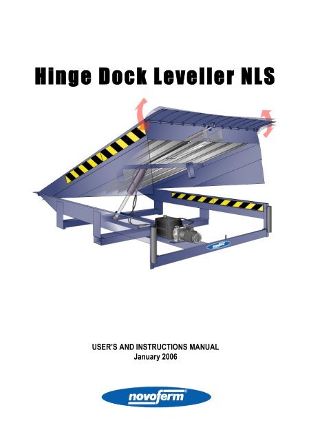
Hinge Dock Leveller NLS - Novoferm
Hinge Dock Leveller NLS - Novoferm
Hinge Dock Leveller NLS - Novoferm

Create successful ePaper yourself
Turn your PDF publications into a flip-book with our unique Google optimized e-Paper software.
<strong>Hinge</strong> <strong>Dock</strong> Leve lle r <strong>NLS</strong><br />
USER’S AND INSTRUCTIONS MANUAL<br />
January 2006
INDEX<br />
The user’s and instructions manual is an integral part of the supply of the machinery. The user’s and instructions manual contains: all<br />
the documents stating the conformity of the machinery with existing regulations, the detailed description, the usage conditions<br />
foreseen, suggestions, set-up, usage, maintenance and repair.<br />
All the data that appear in the following manual must be consider approx.<br />
Safety regulations<br />
Declaration 2<br />
Usage of the <strong>Dock</strong> leveller<br />
Usage conditions 3<br />
Maintenance 4<br />
Fundamental warnings related to safety 5<br />
Description of the <strong>Dock</strong> leveller<br />
Dimensions – capacity - structure 6<br />
Functioning 7<br />
Electric diagrams 8-11<br />
Hydraulic diagram 12<br />
Hydraulic power pack 13<br />
Hydraulic oil 14<br />
Cylinders and Connections 15<br />
Maintenance<br />
Troubleshooting 16-17<br />
Annual checks 18<br />
Severe dangerous situations 19<br />
page<br />
GHL_<strong>NLS</strong>_E_V02.doc Page 1 of 19
DECLARATION<br />
Each machine has been manufactured according to the safety regulations presently in force.<br />
Each machine must carry a permanently fixed identification label as the one shown below.<br />
Each machine comes with a conformity declaration according to European regulation UNI CEI EN 45014.<br />
If these machines are used according to all the dispositions contained in this user’s and instruction manual, there will be no harm<br />
to the health of the user, in conformity to Directives 91/155/CE.<br />
For each machine an annual check is necessary.<br />
It is forbidden, in absence of <strong>Novoferm</strong> authorization to make any modifications<br />
that could jeopardize safety.<br />
Improper use , modification of safety devices, lack of maintenance, intervention carried out without<br />
following the written procedures or by non-competent personnel, “nullifies all responsibility by<br />
<strong>Novoferm</strong>” and consequently automatically ceases all forms of insurance or warranty.<br />
GHL_<strong>NLS</strong>_E_V02.doc Page 2 of 19
USAGE CONDITIONS<br />
AIM OF THE<br />
DOCK LEVELLER<br />
TRANSPORT<br />
EQUIPMENT<br />
GRADIENT<br />
RESTING POSITION<br />
The dock leveller is a static or mobile equipment which is used to fill the distance between a loading<br />
dock or similar loading areas and the loading surface of a vehicle that can be at different levels.<br />
The dock leveller is not designed to lift or lower goods.<br />
The operation is therefore not intended to lift the load, but only to modify the position of the dock<br />
leveller, without any load.<br />
The dock leveller is not suitable to carry loads if it is not perfectly resting in a balanced position on the<br />
vehicle surface.<br />
A safety area of 350 mm. on both sides must be foreseen.<br />
The transport equipment width will then be equal to the dock leveller plate minus 700 mm.<br />
<strong>Dock</strong> leveller width 1750 transport equipment width 1050 mm<br />
<strong>Dock</strong> leveller width 2000 transport equipment width 1300 mm<br />
<strong>Dock</strong> leveller width 2200 transport equipment width 1500 mm<br />
The maximum dock leveller gradient, during loading operations, must not exceed 12.5% of its length.<br />
The maximum dock leveller gradients are applied only when using forklifts. In the case of transpallet<br />
usage, both manual or electrical, the gradient is to be reduced to 5 %.<br />
If the dock leveller features a straight lip, use the dock leveller with negative gradients only; in case of<br />
positive gradients there is in fact a impact risk.<br />
The maximum usage gradient is shown by means of orange fluorescent stripes placed on the swinging<br />
side panels. In case these stripes are visible, the dock leveller must not be used.<br />
When in the resting position, the dock leveller lip must be in a perfect vertical position, laying on its<br />
appropriate supports and the dock leveller must form a continuous surface with the floor.<br />
Only in this position the load can pass over the dock leveller, in whatever direction.<br />
WORKING<br />
POSITION<br />
FREE SWINGING<br />
CONDITIONS<br />
ROOM<br />
TEMPERATURE<br />
Transit over the dock leveller during loading / unloading operations is allowed only if the lip is perfectly<br />
extended and laying for its entire length on the vehicle surface.<br />
The load can pass on the dock leveller only in the longitudinal direction (axis dock leveller-lorry tray).<br />
While in the working position, the dock leveller must be left free of swinging both vertically and<br />
crosswise. Vertical swinging is allowed by releasing the working controls. Crosswise swinging, that<br />
equals to 5% of the total dock leveller length approximately, is obtained as a result of the particular<br />
structure flexibility.<br />
Room temperature must be between –10° and + 40° degrees Celsius.<br />
GHL_<strong>NLS</strong>_E_V02.doc Page 3 of 19
MAINTENANCE<br />
All maintenance and/or repair operations must be performed by a ‘competent person’. The European<br />
regulation EN 1398 defines as a competent person: ‘who that, according to the experience and the<br />
technical training received has sufficient knowledge in the dock leveller field and has familiarity with<br />
the dock leveller adjustment to allow its functioning’.<br />
It is strictly forbidden to carry out maintenance or repairs on a working dock leveller; operations like<br />
cleaning, adjustment or repairs need to be performed with the dock leveller standing still.<br />
All maintenance or repairs operations that must be done under the dock leveller must be carried out<br />
without any load and after inserting the maintenance support device.<br />
Verify the maintenance setting, because uncorrected works could have broken it.<br />
BEFORE EACH USE<br />
Verify that the dock leveller has not suffered any external damage after a collision.<br />
Also verify that both the rear and front hinges are free from debris and/or dirt, that could jeopardize the total and/or partial rotation of<br />
the lip.<br />
This is not really a maintenance operation, but only a simple visual check of tidiness of the working area.<br />
This kind of check must be performed by the operator each time there is the loading/unloading operation of a new lorry, see also on<br />
page 10.<br />
MAINTENANCE AND ANNUAL CHECKS<br />
• At least once every year dock levellers must undergo all checks, as described on page 17<br />
• The user will then have to keep all the test certificates and show them on request by the Competent Authorities.<br />
TRIENNIAL MAINTENANCE<br />
Oil duration depends on different factors like: amount of working hours, presence of debris/impurities, possible humidity; the oil has<br />
to be replaced when features like limpidity or fluidity are missing.<br />
In any case it will be necessary to replace the oil every 3 years.<br />
SIX-YEARLY MAINTENANCE<br />
Every 6 years it will be necessary to replace all flexible hydraulic pipes<br />
OUT OF ORDER<br />
During the maintenance phases, must be exposed on the machine, in a noticeable way, the appropriate advertising poster of “Out of<br />
order maintenance”. To carry on this operation is necessary to commutate the general switch on OFF position, and lock it on.<br />
GHL_<strong>NLS</strong>_E_V02.doc Page 4 of 19
FUNDAMENTAL WARNING RELATED TO SAFETY<br />
All dock levellers feature all the necessary safeties to avoid, for what it is reasonably possible, every risk.<br />
This is the case of machines that operate with electrical power tension, and that feature appliances moving and/or rotating, and<br />
therefore it is required to operate with extreme care.<br />
DOCK LEVELLER USERS<br />
All people that use the dock levellers must be 18 years of age or older. These people must be expressly put in charge by the<br />
Company to operate the dock levellers, not before a proper training period and after having carefully read the user’s and instruction<br />
manual.<br />
SCOPE OF THE DOCK LEVELLER<br />
The dock leveller is a static equipment fit to level all differences in height and gaps between a loading point (or similar loading areas)<br />
and the surface of a vehicle, and designed solely to allow loading (or unloading) operations.<br />
Therefore the functioning is not intended to lift the load, but only to modify the position of the dock leveller, without any load.<br />
The dock leveller is not suitable to carry loads if it is not perfectly laying in a balanced way on the surface of the vehicle.<br />
USE OF THE DOCK LEVELLER<br />
Use the dock leveller only according to the directions and only if it is in perfect technical condition. Remove and/or have removed<br />
whatever matter that could jeopardize safety.<br />
Before operating the up and/or down controls, check that nobody could be in a situation of danger due to the motion of the dock<br />
leveller.<br />
GHL_<strong>NLS</strong>_E_V02.doc Page 5 of 19
DIMENSIONS - CAPACITY - STRUCTURE<br />
CAPACITY<br />
The nominal capacity of our dock levellers is 6.000 Kg., of which 90%, that is to say 5.400 Kg., can sit on a single axis of the forklift if<br />
it has its front wheels at least 250 mm. wide, and that the single axis weight on a single wheel is therefore equal to 2.700 kg.<br />
For all loading operations it is possible to use forklifts, electrical or manual transpallets or other similar equipment.<br />
It is expressly forbidden to use forklifts weighing more than 6.000 Kg. when fully loaded.<br />
Modell A B C D E F G H I<br />
weight<br />
kg<br />
20/17,5 1750 1930 90 850<br />
20/20 2000 2000 600 2320 2180 2080 290 290 95 970<br />
20/22 2200 2380 100 1090<br />
25/17,5 1750 1930 110 1190<br />
25/20 2500 2000 600 2820 2180 2580 320 300 120 920<br />
25/22 2200 2380 125 1040<br />
30/17,5 1750 1930 120 1170<br />
30/20 3000 2000 600 3320 2180 3080 340 300 135 1270<br />
30/22 2200 2380 140 970<br />
34/17,5 1750 1930 140 1100<br />
34/20 3400 2000 600 3720 2180 3480 360 300 150 1230<br />
34/22 2200 2380 155 1330<br />
N.B.<br />
G and H values are referring to models featuring bent lip only the value “E” is referring only to the dock leveller with side<br />
walls (method B, C, D1, D2 and E),for the pit mounted (method A) type E=B<br />
STRUCTURE – SAFETY VALVE OPERATION<br />
Inserted at the base of the raising cylinder of the dock leveller there is a balanced valve, that is activated when it is necessary to<br />
reduce the lowering speed of the dock leveller to 0.05 m/s in case the speed suddenly increases (e.g.: a lorry moves before the end<br />
of the loading / unloading operation is completed).<br />
Warning: the operation of the safety valve with a load of more than 2.000 Kg. could damage the dock<br />
<strong>Leveller</strong> structure permanently.<br />
GHL_<strong>NLS</strong>_E_V02.doc Page 6 of 19
FUNCTIONING SILVER<br />
All controls must be positioned in a way that the operator can observe all the movements of both the dock leveller and the load.<br />
Controls are marked and easily understandable.<br />
1<br />
1. Main Switch<br />
2. Operation button<br />
2<br />
FUNCTIONING SEQUENCE<br />
• Let the lorry get close by following the instructions written at the previous page<br />
• Turn the main switch (1) in the ON position, which signals that the panel is fed: after this operation the dock leveller is ready to<br />
work.<br />
• Press the operation button (2), wait until the dock leveller reaches its maximum inclination and the lip is completely open, being a<br />
continuous line with the dock leveller plate.<br />
• Release the operation button and it will start to lower by gravity until reaching the lorry’s box; it is now free to float and ready for<br />
the loading/unloading operations.<br />
• When all loading/unloading operations are finished, press the operation button and wait for the lip to get completely folded.<br />
• Release the operation button and wait until the dock leveller gets to its resting position, with the lip perfectly resting on its lateral<br />
seats.<br />
• Rotate the main switch (1) in the OFF position, which signals that the panel is no longer fed; after this operation the dock leveller<br />
can no longer work.<br />
If the main switch is rotated in the OFF position, the dock leveller will stay still in whichever<br />
position. To restore the functioning it is necessary to rotate it in an anticlockwise way in ON<br />
position and press the operation button.<br />
If the voltage fails, the dock leveller will stay still in whichever position. To restore the cycle<br />
it is necessary (when the voltage resets) to press the operation button that, when released,<br />
will get the floating dock leveller.<br />
GHL_<strong>NLS</strong>_E_V02.doc Page 7 of 19
ELECTRIC DIAGRAMS <strong>NLS</strong><br />
CONTROL BOX<br />
GHL_<strong>NLS</strong>_E_V02.doc Page 8 of 19
ELECTRIC DIAGRAMS <strong>NLS</strong><br />
CONTROLDIAGRAM<br />
GHL_<strong>NLS</strong>_E_V02.doc Page 9 of 19
ELECTRIC DIAGRAMS <strong>NLS</strong><br />
INSTALLATIONDIAGRAM<br />
GHL_<strong>NLS</strong>_E_V02.doc Page 10 of 19
ELECTRIC DIAGRAMS <strong>NLS</strong><br />
For spare parts please refer to the names on each separate component.<br />
For teleruptors and thermal relays it is possible to use without problems Telemecanique, ABB, Siemens etc.<br />
Cable length to the hydraulic power pack: 8 m<br />
The electric panel is always supplied to work with a feeding voltage of 400. However, it’s possible to make it working with a feeding<br />
voltage of 240V changing two wires on the electric ….<br />
For more details, see the following diagram:<br />
GHL_<strong>NLS</strong>_E_V02.doc Page 11 of 19
HYDRAULIC DIAGRAM S-05<br />
POS CODE NAME CHARACTERISTICS<br />
1 - 2 V3.889.04.A32 Max pressure valve VM15 Adjustment field 30 - 120 bar<br />
3 V3.892.25.000 Valve VU3/8”-MD Unidirectional Valve<br />
4 V3.888.25.00G Valve VMS12-L<br />
5 V3.888.24.001 Valve VSS-FR Adjustment field 30 - 120 bar<br />
6 V3.892.90.000 Valve VUPC14 Piloted valve to close<br />
7 V3.896.69.A20 Valve VE1-NC cav. V096004 Electric valve<br />
C1.664.32.OC2 Solenoid S2-CE 24Vdc H Class<br />
8 V3.895.57.000 Valve STM10 Limiting device<br />
9 V2.371.35.011 Diaphragm ¼” Hole Ø1,1<br />
ME ref. Power pack Electric engine See plate<br />
PO ref. Power pack Hydraulic pump Gear type<br />
FA ref. Power pack Suction filter filtering max 90 micron<br />
GHL_<strong>NLS</strong>_E_V02.doc Page 12 of 19
HYDRAULIC PLUNGED MOTOR POWER PACK<br />
+ THERMIC<br />
1. Motor<br />
2. Oil plug<br />
3. Clump box<br />
4. Valve group<br />
5. Pump<br />
6. Filter<br />
MOTOR: • Power: 0,75 Kw<br />
• Nr. Poles: 2 (2780 turns/min.)<br />
• Nominal tension 230 - 400 V, 50 Hz with tolerance on tension and frequency data ± 5%.<br />
• Absorption: 3.6A to 230V; 2.1A to 400V<br />
• ca/cn ratio: 2.8 - cos = 0.78<br />
• Intermittent service S2 = 5 minutes<br />
PUMP: • Type CV6400800C (cubic capacity 1,6 cc)<br />
• Gear type, with fixed capacity 4.5 lt./min.<br />
• It is forbidden to invert the sense of rotation of the pump, even if it is for brief periods of time.<br />
Warning: If the pump works without intaking oil, it will be damaged in an irreparable way<br />
FILTER: • Made of metallic nets, filtering capacity: 90 microns<br />
OIL • Agip ARNICA 22 - Quantity: 4.5 litres<br />
OIL PLUG • The power pack oil plug features an internal air filter, it has a diameter of ½ inch.<br />
POWERPACK CHECK<br />
• Dismount the power pack and position it on the floor or an appropriate working bench; open then the power pack cover.<br />
• Put a container under the plug to replace the oil (placed on the rear power pack side), unscrew the plug and wait until the power<br />
pack is empty.<br />
• Remove possible sediments from the bottom of the tank.<br />
• Dismount the pump filter and clean it with fuel oil; if the filter happens to be jammed, then it is necessary to replace it.<br />
• Add oil equal or with similar features to the one used and filtered with a filtration value equal or less than 90 microns.<br />
• Warning; if sediment or impurities are found in the tank, it is also necessary to dismount all cylinders and pipes and to clean and<br />
wash them with fuel oil.<br />
• Do not dispose the oil in sewers or rivers. It is necessary to collect and bring it to the Competent Authorities for its disposal (DPR<br />
691/82).<br />
• After finish up re-assembling the power pack it is necessary to perform the operation of air clearing; to do so it is sufficient to<br />
make the dock leveler go up and down 3-4 times.<br />
GHL_<strong>NLS</strong>_E_V02.doc Page 13 of 19
HYDRAULIC OIL AGIP ARNICA 22<br />
FEATURES<br />
EQUIVALENT HYDRAULIC OILS<br />
Viscosity at 40° C 22 SHELL – TELLUS T 22<br />
Viscosity at 100° C 5,2 ESSO - INVAROL EP 22<br />
Viscosity index 175 MOBIL - DTE 11<br />
Inflammability edge (°C) 192 CASTROL – HYSPIN AWH 22<br />
Flowing edge (°C) -39<br />
Density at 15° C 0,857<br />
IDENTIFICATION OF DANGERS<br />
This product, when used in the foreseen proper usage conditions, does not present any risk to the user. However, repeated and<br />
extended contact, together with scarce personal hygiene, can cause skin irritation and contact dermatitis.<br />
FIRST AID PROCEDURES<br />
Skin contact<br />
Eye contact<br />
Swallowing<br />
Inhalation of the<br />
product<br />
Wash thoroughly with soap and water<br />
Irrigate the area with abundant water, if the irritation persists contact a specialist<br />
Do not provoke vomiting, in order to avoid inhalation of the product to the lungs, immediately call for a<br />
doctor<br />
If, in the case of spontaneous vomiting there is the reasonable suspicion of inhalation of the product to<br />
the lungs, transport the patient with extreme urgency to the nearest hospital.<br />
In case of exposure to an elevated concentration of oil steams, transport the patient to a steam free area<br />
and call for a doctor<br />
FIRE PREVENTION PROCEDURES<br />
• To extinguish fire use: CO2 foam, chemical dust: avoid using water extinguishers.<br />
• Cover all machinery not touched by fire with foam or soil.<br />
• Cool down all surfaces not touched by fire with water.<br />
ACCIDENTAL LEAKING PROCEDURES<br />
Floor shadings<br />
Water shadings<br />
Contain the leakage of the product with sand or soil, then collect it and send it to be reduced to<br />
ash<br />
Remove the shed product using mechanical means, then inform the Authorities about the<br />
accident<br />
PRODUCT DISPOSAL<br />
Do not dispose of the oil in sewers or rivers. It is necessary to collect and bring it to the Competent Authorities for its disposal.<br />
OIL CHANGE<br />
Oil duration depends on different factors like: amount of working hours, presence of debris/impurities, possible humidity; it has to be<br />
replaced when features like limpidity or fluidity are missing.<br />
In any case it is necessary to replace the oil at least every 3 years. Quantity 4.5 litres<br />
GHL_<strong>NLS</strong>_E_V02.doc Page 14 of 19
CYLINDERS AND FLEXIBLE PIPES<br />
460<br />
RAISING CYLINDER GASKETS<br />
POS. MOD. POLYPAC GASKET<br />
1 WNE BUSAK 000500<br />
2 BALSELA 236196<br />
3 OR 142<br />
4 SEEGER Ø 46X54<br />
LIP CYLINDER GASKETS<br />
1 WNE BUSAK 000250<br />
2 BALSELA 129098/1<br />
3 DU BUSH Ø 25X20<br />
230<br />
All mounting, dismounting or adjustment operations that must be done under the dock leveller must be carried<br />
out after inserting the maintenance support device.<br />
Beware that all max. pressure valves must be regulated only by authorized personnel, which have to seal all<br />
valves after regulation according to the existing Safety Rules.<br />
GHL_<strong>NLS</strong>_E_V02.doc Page 15 of 19
MAINTENANCE<br />
TROUBLESHOOTING<br />
In case of improper functioning of the dock leveller it is suggested firstly to carry out the following checks :<br />
• Carry out a careful visual check of the dock leveller in its entirety, making sure that the main structure does not have<br />
deformations, damages and / or bumps that could jeopardize the proper functioning.<br />
• Check that the flexible pipes are not bent excessively, are not squeezed or damaged.<br />
• Check that all bolts, nuts and joints to the flexible pipes are not loose and that there is not any oil leakage.<br />
• Make sure that all electric wires are not disconnected or cut.<br />
• Also check that there are not any mechanical obstacles that can block the correct total and/or partial sequence of the dock<br />
leveller movements . In fact, sometimes the dock leveller can be obstructed in its movements by impurities or foreign bodies.<br />
TROUBLE SHOOTING<br />
DEFECT CAUSE SOLUTION<br />
The dock leveller does not<br />
raise<br />
1: the electric motor does not start<br />
Check the power feeding, all contactors and the<br />
motor safety device<br />
2: the electric motor is burnt Replace the electric motor<br />
3: the sense of rotation of the motor is not correct Invert the feeding phases<br />
1: the side protections are jammed Clean the slidings and set up them manually<br />
The dock leveller moves in<br />
spurts<br />
2: foreign bodies in the rear and front hinges Remove dirt or foreign bodies<br />
3: the oil level is insufficient Add hydraulic oil<br />
4: the dock leveller is blocked by a mechanical<br />
resistance<br />
Remove the obstacle<br />
1: the motor is working with two phases or is<br />
underfed<br />
2: oil leakages from a pipeline Fasten the joints<br />
Check the electric connection and the line tension<br />
The dock leveller raises<br />
slowly<br />
3: the dock leveller is overloaded, the max<br />
pressure valve has intervened<br />
Remove the load<br />
4: the pump filter is jammed Dismount and clean the filter (replace it if needed)<br />
5: air intaking in the intaking pipe Check the fastening<br />
6: leakage from the valve group due to melting<br />
defects<br />
Replace the valve group<br />
GHL_<strong>NLS</strong>_E_V02.doc Page 16 of 19
MAINTENANCE<br />
TROUBLE SHOOTING<br />
DEFECT CAUSE SOLUTION<br />
1: no feeding to the electrovalve Check the electric system<br />
2: the electrovalve coil is burnt Replace the coil<br />
3: the support device is inserted Remove the support device<br />
The dock leveller does not<br />
lower<br />
4: the safety valve activates because the load has<br />
been loaded on the dock leveller without the lip<br />
resting properly on the lorry tray<br />
5: the safety valve activates because of excessive<br />
density of the oil due to presence of dirt<br />
6: the safety valve activates because of excessive<br />
density of the oil due to room temperature less<br />
than - 10° C.<br />
Remove the load<br />
Replace the oil<br />
Replace the oil with one suitable for lower<br />
temperatures<br />
GHL_<strong>NLS</strong>_E_V02.doc Page 17 of 19
MAINTENANCE<br />
ANNUAL CHECKS<br />
Once a year, all dock levellers must undergo tests and checks. The checks, besides verifying suitability to safety requirements and<br />
dimensioning, must in particular include:<br />
• Visual checks concerning wearing and external damage.<br />
• Check of all functions (functioning cycle)<br />
• Check of the presence and efficiency of all safety installations (automatic safety device check and max pression valve<br />
adjustment check).<br />
It is necessary to perform the following checks and interventions:<br />
• Check that the main structure of the dock leveller does not show any deformation, damage or bumps that could jeopardize its<br />
correct functioning.<br />
• Check that the support device of the dock leveller is perfectly joined with it, that its hinge is in good condition and that it fits<br />
correctly into its seat.<br />
• Check that there are the yellow/black stripes on the sides of the plate and on the side panels of the chassis; check that they are<br />
not worn out and still perfectly visible.<br />
• Check the lateral flexibility of the dock leveller, which must equal approximately 5% of its total length.<br />
• Check that the cylinder is free of damage, scratches, rust or foreign bodies on the hinge of the piston.<br />
• Check that the flexible pipes are not bent excessively, squeezed or damaged.<br />
• Check that the electric wires are not cut or worn out.<br />
• Check that all bolts, nuts, joints and pipes are not loose and that there is not any leakage of oil from the cylinder and from the<br />
pipes.<br />
• Clean the hinging of the lip if necessary.<br />
Beware that it is necessary to replace the power pack oil at least once every 3 years.<br />
Also remember that after a working period of 6 years it is necessary to replace all flexible pipes.<br />
Every annual check needs to be recorded using its appropriate form. Lack of recording of this form<br />
will automatically nullify every form of insurance and/or warranty.<br />
GHL_<strong>NLS</strong>_E_V02.doc Page 18 of 19
MAINTENANCE<br />
SEVERE DANGEROUS SITUATIONS<br />
It’s important to underline that there are situations that can cause mortal danger.<br />
Lorry approach phase<br />
• Beware that no operator and no obstruction should be between the dock and the retreating truck.<br />
<strong>Dock</strong> leveller location phase<br />
• The user must be in place to follow easily all the dock leveller motions. This ensures him to action the controls only when the<br />
positioning is without the presence of loads, or there are not people on or in the vicinity of the dock leveller.<br />
Usage phase<br />
• The user authorizes the carry/unload only when the lip is correctly laying on the lorry tray, he can’t see the orange stripes that<br />
marked the maximum working gradient; the driver has provided the vehicle keys.<br />
• The forklift fully loaded weight including the operator, must not be greater than nominal carrying showed on the plate (6000<br />
daN).<br />
• The loading process must be carried out with forklifts for which the difference between the lorry tray width and the lifting device<br />
width should be less than 700 mm.<br />
• Don’t use the ramp for rising people.<br />
• The load overtake on the dock leveller is allowed only if the lip should be in a perfect vertical position, correctly laid on its<br />
supports and the dock leveller must form a continuous surface with the floor.<br />
Maintenance phase<br />
• Make sure that the safety maintenance bar is properly engaged.<br />
• Verify that the bar-fixed support has not been damaged by previously incorrectly usages.<br />
D o n ’ t u s e t h e l e v e l l e r i f y o u c a n s e e<br />
s i g n o f s a f e t y s y s t e m s t a m p e r i n g .<br />
GHL_<strong>NLS</strong>_E_V02.doc Page 19 of 19