SERVICE MANUAL LC-XB41 - TechEdu.com
SERVICE MANUAL LC-XB41 - TechEdu.com
SERVICE MANUAL LC-XB41 - TechEdu.com

You also want an ePaper? Increase the reach of your titles
YUMPU automatically turns print PDFs into web optimized ePapers that Google loves.
Electrical Adjustments<br />
Gain adjustment [Component]<br />
1. Enter the service mode.<br />
2. Receive the 16-step grey scale 480i-<strong>com</strong>ponent signal<br />
with Computer2 [Component] mode.<br />
3. Connect an oscilloscope to test point “TP35G” (+) and<br />
chassis ground (-).<br />
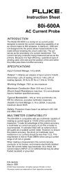
4. Select group no. “0”, item no. “3” and adjust the amplitude<br />
“a” to be minimum by changing the Data value.<br />
(a)<br />
White Level<br />
n Common Center adjustment<br />
1. Enter the service mode.<br />
2. Receive the 50%-Whole Gray <strong>com</strong>puter signal with<br />
Computer1 [RGB] mode.<br />
3. Select group no. “100”, item no. “92” and change<br />
data value to “2” to reduce the panel frequency.<br />
4. Project only green light <strong>com</strong>ponent to the screen.<br />
5. Select group no. “101”, item no. “1” and change data<br />
value to obtain the minimum flicker on the screen.<br />
6. Project only red light <strong>com</strong>ponent to the screen.<br />
7. Select item no. “0” and change data value to obtain<br />
the minimum flicker on the screen.<br />
8. Project only blue light <strong>com</strong>ponent to the screen.<br />
9. Select item no. “2 and change data value to obtain<br />
the minimum flicker on the screen.<br />
10. Select group no. “100”, item no. “92” and change<br />
data value to “0” to reset the panel frequency.<br />
b Auto Calibration adjustment [Video]<br />
1. Enter the service mode.<br />
2. Receive the 16-step grey scale <strong>com</strong>posite video signal<br />
with Video [Video] mode.<br />
3. To start the auto-calibration for Component adjustment,<br />
select group no. “260”, item no. “0” and then<br />
change data value from “0” to “1”. After the auto-calibration<br />
<strong>com</strong>pleted, "OK" will appear on the screen.<br />
m 50% White adjustment [PC]<br />
1. Enter the service mode.<br />
2. Receive the 16-step grey scale <strong>com</strong>puter signal with<br />
Computer1 [RGB] mode.<br />
3. Connect an oscilloscope to test point “TP35G” (+)<br />
and chassis ground (-).<br />
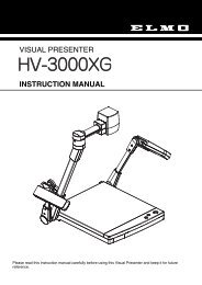
4. Select group no. “100”, item no. “6” and change data<br />
value to adjust amplitude “a” to be 1.6 ±0.1V.<br />
Below adjustment is performed when the above auto<br />
calibration is failed.<br />
Gain adjustment [Video]<br />
1. Enter the service mode.<br />
2. Receive the 16-step grey scale <strong>com</strong>posite video signal<br />
with Video [Video] mode.<br />
3. Connect an oscilloscope to test point “TP35G” (+) and<br />
chassis ground (-).<br />
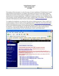
4. Select group no. “20”, item no. “0” and adjust the amplitude<br />
“a” to be minimum by changing the Data value.<br />
(a)<br />
White Level<br />
white level<br />
, White Balance adjustment [PC]<br />
1. Enter the service mode,<br />
2. Receive the 16-step gray scale <strong>com</strong>puter signal with<br />
Computer1 [RGB] mode.<br />
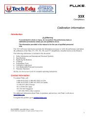
3. Select group no. “100” item no. “7” (Red) or “8” (Blue),<br />
and change Data values respectively to make a proper<br />
white balance.<br />
(a)<br />
white level<br />
Confirm that the same white balance is obtained in video<br />
and <strong>com</strong>puter input.<br />
-29-