SERVICE MANUAL LC-XB41 - TechEdu.com
SERVICE MANUAL LC-XB41 - TechEdu.com
SERVICE MANUAL LC-XB41 - TechEdu.com

Create successful ePaper yourself
Turn your PDF publications into a flip-book with our unique Google optimized e-Paper software.
Electrical Adjustments<br />
x Panel Type Check and Setting<br />
* Before setting, you need to check which type of <strong>LC</strong>D panel<br />
is placed on the projector according to the item "<strong>LC</strong>D<br />
Panel/Prism Ass'y removal" in the chapter "Optical Parts<br />
Disassembly".<br />
1. Enter the service mode.<br />
2. Panel Type Check<br />
Select group no. “290”, item no. “0”. Check the data<br />
value as follows;<br />
Data value: 0 For L-Type of <strong>LC</strong>D Panel<br />
Data value: 20 For R-Type of <strong>LC</strong>D panel<br />
3. Panel Type Setting<br />
Select group no. “290”, item no. “1” and change data<br />
value from 10 to 0 or 20 depending on your <strong>LC</strong>D Panel<br />
type. When the data value reaches 0 or 20, it returns<br />
to 10 quickly. The gamma-characteristics changes according<br />
to your selection.<br />
Gain adjustment [PC]<br />
1. Enter the service mode.<br />
2. Receive the 16-step grey scale <strong>com</strong>puter signal with<br />
Computer1 [RGB] mode.<br />
3. Connect an oscilloscope to test point “TP35G” (+) and<br />
chassis ground (-).<br />
4. Select group no. “0”, item no. “3” and adjust the amplitude<br />
“a” to be minimum by changing the Data value.<br />
5. Connect an oscilloscope to test point “TP35R” (+) and<br />
chassis ground (-).<br />
6. Select group no. “0”, item no. “4” and adjust the amplitude<br />
“a” to be minimum by changing the Data value.<br />
7. Connect an oscilloscope to test point “TP35B” (+) and<br />
chassis ground (-).<br />
8. Select group no. “0”, item no. “5” and adjust the amplitude<br />
“a” to be minimum by changing the Data value.<br />
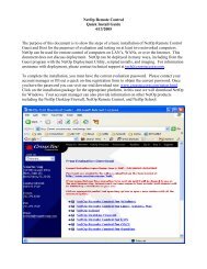
White Level<br />
(a)<br />
c Auto Calibration adjustment [PC]<br />
1. Enter the service mode.<br />
2. Receive the 16-step grey scale <strong>com</strong>puter signal with<br />
Computer1 [RGB] mode.<br />
3. To start the auto-calibration for PC adjustment, select<br />
group no. “260”, item no. “0” and then change data<br />
value from “0” to “1”. After the auto-calibration <strong>com</strong>pleted,<br />
"OK" will appear on the screen.<br />
Below adjustments are performed when the above auto<br />
calibration is failed.<br />
Pedestal adjustment [PC]<br />
1. Enter the service mode.<br />
2. Receive the 16-step grey scale <strong>com</strong>puter signal with<br />
Computer1 [RGB] mode.<br />
3. Connect an oscilloscope to test point “TP35G” (+) and<br />
chassis ground (-).<br />
4. Select group no. “0”, item no. “0” and change data value<br />
to adjust the pedestal level and black level to be the<br />
same level.<br />
5. Connect an oscilloscope to test point “TP35R” (+) and<br />
chassis ground (-).<br />
6. Select item no. “1” and change data value to adjust the<br />
pedestal level and black level to be the same level.<br />
7. Connect an oscilloscope to test point “TP35B” (+) and<br />
chassis ground (-).<br />
8. Select item no. “2” and change data value to adjust the<br />
pedestal level and black level to be the same level.<br />
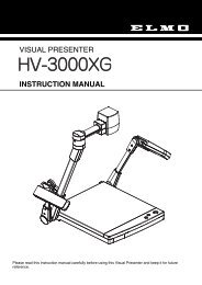
Black Lebel<br />
Pedestal Lebel<br />
v Auto Calibration adjustment [Component]<br />
1. Enter the service mode.<br />
2. Receive the 16-step grey scale 480i-<strong>com</strong>ponent signal<br />
with Computer2 [Component] mode.<br />
3. To start the auto-calibration for Component adjustment,<br />
select group no. “260”, item no. “0” and then<br />
change data value from “0” to “1”. After the auto-calibration<br />
<strong>com</strong>pleted, "OK" will appear on the screen.<br />
Below adjustments are performed when the above auto<br />
calibration is failed.<br />
Pedestal adjustment [Component]<br />
1. Enter the service mode.<br />
2. Receive the 16-step grey scale 480i-<strong>com</strong>ponent signal<br />
with Computer2 [Component] mode.<br />
3. Connect an oscilloscope to test point “TP35G” (+) and<br />
chassis ground (-).<br />
4. Select group no. “0”, item no. “0” and change data value<br />
to adjust the pedestal level and black level to be the<br />
same level.<br />
5. Connect an oscilloscope to test point “TP35R” (+) and<br />
chassis ground (-).<br />
6. Select item no. “1” and change data value to adjust the<br />
pedestal level and black level to be the same level.<br />
7. Connect an oscilloscope to test point “TP35B” (+) and<br />
chassis ground (-).<br />
8. Select item no. “2” and change data value to adjust the<br />
pedestal level and black level to be the same level.<br />
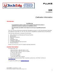
Black Lebel<br />
Pedestal Lebel<br />
-28-