SERVICE MANUAL LC-XB41 - TechEdu.com
SERVICE MANUAL LC-XB41 - TechEdu.com
SERVICE MANUAL LC-XB41 - TechEdu.com

You also want an ePaper? Increase the reach of your titles
YUMPU automatically turns print PDFs into web optimized ePapers that Google loves.
Electrical Adjustments<br />
Circuit Adjustments<br />
CAUTION: The each circuit has been made by the fine adjustment at factory. Do not attempt to adjust the following<br />
adjustments except requiring the readjustments in servicing otherwise it may cause loss of performance<br />
and product safety.<br />
WARNING : USE UV RADIATION EYE AND SKIN<br />
PROTECTION DURING SERVICING.<br />
CAUTION: <br />
To prevent suffer of UV radiation, those adjustments<br />
must be <strong>com</strong>pleted within 25 minutes.<br />
[Adjustment Condition]<br />
● Input signal<br />
Video signal ........................1.0Vp-p/75W terminated, 16 steps gray scale<br />
(Composite video signal)<br />
Component Video signal......0.7Vp-p/75W terminated, 16 steps gray scale<br />
(Component video signal)<br />
Computer signal...................0.7Vp-p/75W terminated, 16 steps gray scale<br />
pattern<br />
● Image mode......................“STANDARD” mode unless otherwise noted.<br />
16 steps gray scale pattern<br />
Note:<br />
* Please refer to “Service Adjustment Menu Operation” for entering the service<br />
mode and adjusting the service data.<br />
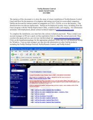
White 100% Black 100%<br />
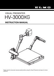
Output Voltage adjustment<br />
After replacing the Power Board readjust the Output voltage<br />
adjustment as follows.<br />
1. Connect a digital voltmeter to pins 2 (+) and 1 (-) of<br />
K6A.<br />
2. Adjust the voltage by using VR601 as following.<br />
AC Input Reading<br />
230V 370V ±2V<br />
Caution:<br />
Be sure to connect the lamp when taking this adjustment.<br />
* This adjustment is not required even if the power board<br />
is replaced because this adjustment is carried out before<br />
parts shipment.<br />
z Fan Control adjustment<br />
1. Enter the service mode.<br />
2. Connect a digital voltmeter to test point “TPFANA” (+)<br />
and chassis ground (-). Select group no. “250”, item<br />
no. “0” and change data value to adjust voltage to be<br />
5.0 ±0.1V.<br />
3. Connect a digital voltmeter to test point “TPFANB” (+)<br />
and chassis ground (-). Select item no. “2” and change<br />
data value to adjust voltage to be 5.0 ±0.1V.<br />
4. Connect a digital voltmeter to test point “TPFANC” (+)<br />
and chassis ground (-). Select item no. “4” and change<br />
data value to adjust voltage to be 5.0 ±0.1V.<br />
5. Connect a digital voltmeter to test point “TPFANA” (+)<br />
and chassis ground (-). Select item no. “1” and change<br />
data value to adjust voltage to be 13.5 ±0.1V.<br />
6. Connect a digital voltmeter to test point “TPFANB” (+)<br />
and chassis ground (-). Select item no. “3” and change<br />
data value to adjust voltage to be 13.5 ±0.1V.<br />
7. Connect a digital voltmeter to test point “TPFANC” (+)<br />
and chassis ground (-). Select item no. “5” and change<br />
data value to adjust voltage to be 13.5 ±0.1V.<br />
-27-