EN_GT100_Express_WDB.. - Global Tardif Groupe manufacturier d ...
EN_GT100_Express_WDB.. - Global Tardif Groupe manufacturier d ...
EN_GT100_Express_WDB.. - Global Tardif Groupe manufacturier d ...

Create successful ePaper yourself
Turn your PDF publications into a flip-book with our unique Google optimized e-Paper software.
<strong>GT100</strong>-C <strong>Express</strong><br />
WORK BY OTHERS<br />
PROJECT #: _______<br />
PROJECT NAME: __________________<br />
PROJECT MANAGER: ___________<br />
REFER TO THIS DOCUM<strong>EN</strong>T BEFORE<br />
ANY INSTALLATION AND BEFORE<br />
APPROVING THE FOLLOWING DRAWINGS
SPECIFICATIONS<br />
Project<br />
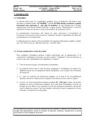
1. G<strong>EN</strong>ERAL<br />
1.1 Scope<br />
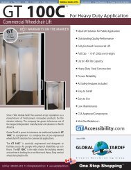
HANDICAP LIFT<br />
HYDRAULIC <strong>GT100</strong>-C EXPRESS<br />
COMMERCIAL TYPE<br />
Section<br />
14 000<br />
Page 2 sur 12<br />
2011-05-20<br />
Furnish all labour, materials and equipment required to install an handicap hydraulic and<br />
cables (2:1) elevator model GT-100C-EXPRESS commercial type, manufactured by <strong>Global</strong><br />
<strong>Tardif</strong> Elevator Manufacturing Group inc. (here after called the Manufacturer) as shown on<br />
the drawings and specifications.<br />
The Manufacturer will supply shop drawings, materials and equipment to the installer<br />
company. Elevator construction works shall not start before drawings have been<br />
approved by owner or general contractor.<br />
The Manufacturer is located at 120 de Naples, St-Augustin de Desmaures, Québec,<br />
Canada (T. 418 878 4116 or le 1.800.661.6316; Fax 418.878.1595).<br />
1.2 Preparatory work by others<br />
To complete the elevator installation, others works have to be done by others:<br />
1. All masonry works, gyproc and paint.<br />
2. A steel girder installed at hoistway ceiling to lift elevator equipment during installation.<br />
3. Hoistway have to be built as per elevator shop drawings, (structural reinforcing,<br />
ventilation etc…) and follow all applicable codes and standards.<br />
4. The pit depth standard minimum is 10’’ (254 mm) The pit shall be clean and built as per<br />
code regulations. Provide pit waterproofing or sumps pump if required. Provide adequate<br />
support for guide rail fastenings.<br />
5. Provide level concrete pit floor to support loads impact. To be able to know the support<br />
load impact, do the following calculations:<br />
Gross load (capacity + cab weight) x 2, 5 = Support load impact (as per chapter 1 of<br />
construction code).<br />
Support Load Impact = _____ lbs (Please Complete)<br />
N.B.: See at: http://www.gtaccessibility.com/CabWeightChart.pdf the Cabin weight<br />
Chart for each model.<br />
6. Hoistway walls, to be built square and plumb all over height with a maximum tolerance<br />
within ¼’’ (6mm). Hoistway walls, with smooth interior surfaces without any bumps.<br />
<strong>Global</strong> <strong>Tardif</strong> Elevator Manufacturing Group inc. reserves the right to discontinue models or options at any<br />
time or change the specifications, warranty terms, materials, equipment or others without notice and without<br />
incurring obligation.
SPECIFICATIONS<br />
Project<br />
HANDICAP LIFT<br />
HYDRAULIC <strong>GT100</strong>-C EXPRESS<br />
COMMERCIAL TYPE<br />
Section<br />
14 000<br />
Page 3 sur 12<br />
2011-05-20<br />
7. Provide a lockable room to store elevator parts and equipment before and during<br />
installation.<br />
8. Machine room to meet or exceed Canadian C.E.C. and CAN-CSA-B355-09 codes and<br />
others standards. Provide light and light switch 110 VAC with a minimum of 100 LUX<br />
luminosity at floor level as per regulations. A lockable, exterior opening fire rated door<br />
equipped with an automatic door closer, will secure the access of the machine room<br />
9. Appropriate overhead from upper landing floor up to the hoistway ceiling or under the<br />
steel girder as per elevation drawing from <strong>Global</strong>/<strong>Tardif</strong>.<br />
10. During installation, hoistway landings access, to be fully open at least 8 feet high.<br />
11. Cab floor finishing and installation by others (Maximum load: 2 lbs/square foot).<br />
12. Rough openings for landing floor call stations and signage, as per drawings.<br />
13. Electric power for setting and test on first installation day by electrical contractor.<br />
14. As per National U.S. electric code or Canadian electric code, a fuse disconnect switch for<br />
each elevator connected on a 30 amps circuit equipped with a normally open type contact.<br />
15. As per the same codes, 15 amps 110 volts, 60 hertz disconnect switch for the cab light is<br />
install as indicated on shop drawings. Install 2 wires and one ground from disconnect box<br />
to controller connections.<br />
16. Following section 38 of electric Canadian codes, install an auxiliary contact in the<br />
principal disconnect switch.<br />
17. The disconnect switch is install 20 feet away maximum from the controller and is visible<br />
from there. If not, a second disconnect switch shall be install near the controller.<br />
18. Electric power have to be plug to a fuse main disconnect box with a manual exterior lever<br />
OR to a non-fused disconnect box lockable at ON or OFF position. That disconnect box<br />
should be located as per our layout drawing.<br />
If a 208/230/1phase/60HZ motor is used, and if the building electric power available is<br />
240/1phase/60HZ, 2 wires + 1 neutral +1 ground have to be connect from the disconnect<br />
box to the controller. Provides building disconnect box 30 amps with an auxiliary contact<br />
NC/NO fused 25 amps type D.<br />
If a 208/230/1phase/60HZ motor is used, and if the building electric power available is<br />
208v/3phases/60HZ, 2 wires + 1 neutral +1 ground have to be connect from the<br />
disconnect box to the controller. Provides building disconnect box 30 amps with an<br />
auxiliary contact NC/NO fused 25 amps type D.<br />
If a 208/230/1phase/60HZ motor is used, and if the building electric power available is<br />
600v/3phases/60HZ and if a transfo is supply with the job, 2 wires + 1 ground from<br />
building disconnect box to transfo and, 2 wires + 1 neutral + 1 ground from transfo to<br />
controller should be connected. Provide building disconnect box 15 amps with an<br />
auxiliary contact NC/NO fused 15 amps type D.<br />
<strong>Global</strong> <strong>Tardif</strong> Elevator Manufacturing Group inc. reserves the right to discontinue models or options at any<br />
time or change the specifications, warranty terms, materials, equipment or others without notice and without<br />
incurring obligation.
SPECIFICATIONS<br />
Project<br />
HANDICAP LIFT<br />
HYDRAULIC <strong>GT100</strong>-C EXPRESS<br />
COMMERCIAL TYPE<br />
Section<br />
14 000<br />
Page 4 sur 12<br />
2011-05-20<br />
N.B. It is owner &/or general contractor responsibility to validate final amperage as per<br />
elevator electric drawings<br />
19. If a 600v/3phases/60HZ motor is used, and if the building electric power available is<br />
600v/3phases/60HZ, you will have to provide 3 wires + 1 ground from building<br />
disconnect box to controller. Provide building disconnect box 15 amps with auxiliary<br />
contact NC/NO fused 6 to 7 amps type D.<br />
Only elevator equipment and elevator electric pipes are allowed in machine room.<br />
N.B. It is owner &/or general contractor responsibility to validate final amperage as per<br />
elevator electric drawings<br />
20. Temperatures between 15 and 32 Celsius have to be constantly kept in the machine room.<br />
20. Light, light switch and electric outlet in hoistway and machine room are required before<br />
starting elevator installation.<br />
<br />
IMPORTANT<br />
1. The elevator drawings are made in accordance of CAN-CSA-B355-09 codes.<br />
2. These drawings are not done for the building construction. It is to illustrate the relation<br />
between the elevator and the structure.<br />
3. This drawing is only for installation. The landing doors details and cab details will be on<br />
separates pages.<br />
4. <strong>Global</strong>/<strong>Tardif</strong> is not responsible for the exact details and dimensions of the hoistway<br />
structure and the machine room.<br />
5. The owner/buyer/builder will provide suitable lintels over and under landing entrances.<br />
6. The doorframes are not built to support the weight of the walls. The general contractor is<br />
responsible for any damages caused by masonry and finishing works around the landing<br />
doors.<br />
7. The total distance between the lower and the upper floor as per elevation drawing have to<br />
be maintain within ¼’’ (6mm).<br />
8. Provide adequate support for guide rail fastenings or for towers supports as per shop<br />
drawings.<br />
<strong>Global</strong> <strong>Tardif</strong> Elevator Manufacturing Group inc. reserves the right to discontinue models or options at any<br />
time or change the specifications, warranty terms, materials, equipment or others without notice and without<br />
incurring obligation.
SPECIFICATIONS<br />
Project<br />
HANDICAP LIFT<br />
HYDRAULIC <strong>GT100</strong>-C EXPRESS<br />
COMMERCIAL TYPE<br />
Section<br />
14 000<br />
Page 5 sur 12<br />
2011-05-20<br />
9. Provide finish grouting and masonry around doorframes only after the end of their<br />
installation.<br />
1.3 Warranty<br />
The Manufacturer’s acceptance is conditional on the understanding that their warranty covers<br />
defective material. The guarantee period shall not extend longer than one year from the date<br />
of completion or acceptance thereof by beneficial user whichever is earlier of each elevator.<br />
The guarantee excludes ordinary wear and tear of improper use, vandalism, abuse, misuse, or<br />
neglect or any other causes beyond the control of the Manufacturer and this express warranty<br />
is in lieu of all other warranties, express or implied, including any warranty of<br />
merchantability or fitness for a particular purpose.<br />
Labour is guaranteed for one year by the installer.<br />
1.4 Maintenance<br />
Elevator Installation Company will provide a quality maintenance contract including<br />
verifications, adjustment and lubrication of the equipment regularly every 3 months after the<br />
elevator delivery day (we recommend a monthly maintenance for unit subject to extensive<br />
operation). The maintenance shall be done by skilled mechanicals during day work time.<br />
Urgent calls will be carried out during normal day time. Maintenance contract will not cover<br />
service calls caused by negligence, abusive use or accident due by others than elevator<br />
installer. Only originals elevator parts can be used for reparations.<br />
1.5 ‘Corrostop-2000’ Paint finish<br />
The elevator manufacturer will paint all exposed parts without finish with GT-CorroStop-<br />
2000 process.<br />
1.6 Permit/ Inspections<br />
The elevator installer will attend to all inspections and verifications required by authorities.<br />
The owner will be responsible for the cost of any license issue by government inspectors.<br />
1.7 Codes<br />
All works have to be done in accordance with Canadian Electrical Code, Provincial Elevator<br />
code and CAN/C.S.A.-B355-09 standard as well as any local code applicable. The<br />
manufacturer is not responsible for any changes in regulations or codes.<br />
<strong>Global</strong> <strong>Tardif</strong> Elevator Manufacturing Group inc. reserves the right to discontinue models or options at any<br />
time or change the specifications, warranty terms, materials, equipment or others without notice and without<br />
incurring obligation.
SPECIFICATIONS<br />
Project<br />
HANDICAP LIFT<br />
HYDRAULIC <strong>GT100</strong>-C EXPRESS<br />
COMMERCIAL TYPE<br />
Section<br />
14 000<br />
Page 6 sur 12<br />
2011-05-20<br />
2. PRODUCTS<br />
2.1 Description<br />
Furnish and install:<br />
Operation:<br />
Control type:<br />
Capacity:<br />
Normal speed:<br />
Travel:<br />
Pit :<br />
Overhead :<br />
Hoistway net dimensions:<br />
Platform dimensions :<br />
Net cab dimensions :<br />
Nbr. of Stops<br />
Opening type for each Stops<br />
One (1) hydraulic and cables (2:1) elevator model : <strong>GT100</strong>-C<br />
EXPRESS manufactured by <strong>Global</strong> <strong>Tardif</strong> inc.<br />
Constant pressure<br />
Simple relay controller model GT-EZ100<br />
_1000_____ lbs (454 KG)<br />
30 fpm (0,15m/s)<br />
____ ft ____ in. (Please Complete)<br />
Maximum 23 feet (7 meters)<br />
____ in. (Please Complete)<br />
Absolute Minimum : 10’’ (254 mm)<br />
____ in. (Please Complete)<br />
Standard Minimum: 96’’ (2438mm)<br />
Width : ____ ft ____ in. (Please Complete)<br />
Depth : ____ ft ____ in. (Please Complete)<br />
(Look for standard dimensions at www.gtaccessibility.com)<br />
Look for standard dimensions at www.gtaccessibility.com<br />
Width : ____ ft ____ in. (Please Complete)<br />
Depth : ____ ft ____ in. (Please Complete)<br />
(Look for standard dimensions at www.gtaccessibility.com)<br />
(maximum 21,5 sq.feet)<br />
____ Stops Please Complete)<br />
(Please enter the stop number for each opening types<br />
ex.: Front Only: Stops #1-2-3, Front/Rear: Stop #4)<br />
Opening Stops (ex.: #1-2-3)<br />
Front Only<br />
Front & Rear<br />
<strong>Global</strong> <strong>Tardif</strong> Elevator Manufacturing Group inc. reserves the right to discontinue models or options at any<br />
time or change the specifications, warranty terms, materials, equipment or others without notice and without<br />
incurring obligation.
SPECIFICATIONS<br />
Project<br />
HANDICAP LIFT<br />
HYDRAULIC <strong>GT100</strong>-C EXPRESS<br />
COMMERCIAL TYPE<br />
Section<br />
14 000<br />
Page 7 sur 12<br />
2011-05-20<br />
Landing door net standard size:<br />
Type of doors:<br />
Doors operation:<br />
Cab height :<br />
Car operating panel:<br />
Landing call stations :<br />
36’’ (914mm) width’’ 80’’ (2032’’) height<br />
Hinged swing door model GT-Swing Door<br />
Manual opening (motorized opening in option)<br />
80’’ (2032mm)<br />
Stainless steel plate (1/8’’) Thickness<br />
ABB Chrome framing raised push button<br />
Power supply: 220Volts / 1 Ph /60Hz.<br />
2.2 Mechanical Structure and hydraulic system<br />
The one side cantilever mechanical structure shall include a steel corrosive proof mechanical<br />
system manufactured with high-tech machinery using numeric and laser technology. We<br />
found inside the structure, the hydraulic system, the guide rails, rails supports, guide shoes<br />
and the car sling.<br />
1. The guide shoes shall easily slide along the 8 lbs/feet ‘’T’’ steel guide rails. These rails<br />
shall be installed plumb all over the elevator hoistway height.<br />
2. Adjustable ‘’C’’ rails brackets will ensure rail plumb and stability in case of any bumps<br />
on the supporting wall.<br />
3. Provide guide shoes with TIVAR inserts type UHMW.<br />
4. The bolted and welded car sling shall be fabricated from paint steel members with<br />
adequate bracing to support the platform, the traction cables and the cab.( installation by<br />
one technician possible)<br />
The hydraulic system shall include a cylinder, plunger, hydraulic hoses, and motor, pump,<br />
valve and traction cables.<br />
1. The cylinder shall be manufactured from steel pipe of a sufficient thickness and suitable<br />
safety margin. The top of the cylinder shall be equipped with a cylinder head with an<br />
internal guide-ring and self-adjusting packing.<br />
2. Provide a plunger, manufactured from a steel shaft of a proper diameter machined true<br />
and smooth. The plunger shall be provided with a stop electrically welded to the bottom<br />
to prevent it to leave the cylinder.<br />
<strong>Global</strong> <strong>Tardif</strong> Elevator Manufacturing Group inc. reserves the right to discontinue models or options at any<br />
time or change the specifications, warranty terms, materials, equipment or others without notice and without<br />
incurring obligation.
SPECIFICATIONS<br />
Project<br />
HANDICAP LIFT<br />
HYDRAULIC <strong>GT100</strong>-C EXPRESS<br />
COMMERCIAL TYPE<br />
Section<br />
14 000<br />
Page 8 sur 12<br />
2011-05-20<br />
3. Provide a 1/2’’ (12,7mm) hydraulic rubber hoses with all equipments and fittings for<br />
good elevator operation.<br />
4. Provide a 3 HP minimum submersible type motor and install it inside the oil tank in the<br />
machine room.<br />
5. Provide a GT-100SB Power submersible type pump allowing enough oil flow to move<br />
the cab in UP direction easily and install it in the oil reservoir in the machine room. Use<br />
flexible fittings only.<br />
6. Be sure to provide a valve good enough to ensure exact oil pressure to move the elevator<br />
up. Install it in the oil reservoir.<br />
7. Provide a minimum of two (2) 3/8’’ (9, 5 mm) diameters 8x19 steel cables. They shall be<br />
fixed at cylinder base and at the car sling passing by a 10 ¾’’<br />
(273 mm) diameter pulley attached at the top of the cylinder.<br />
2.3 Pump unit<br />
1. Pump unit shall include: the oil reservoir, the submersible motor and pump and the valve.<br />
2. Provide a steel paint reservoir mounted on four (4) solid steel legs strong enough to<br />
support the weight of the oil, the motor, the pump and the valve with overflow edges on<br />
the cover.<br />
3. The valve shall be equipped with an adjustable pressure relief system, a manually<br />
operating down system to lower elevator if emergency and a system to isolate the<br />
cylinder from the pump unit plus a check valve for down control operation.<br />
4. Provide a negative pressure switch that will be activated when negative pressure is sensed<br />
in the hydraulic system. The check valve will close and stop the hydraulic jack from<br />
descending immediately on sensing negative pressure.<br />
2.4 Flow control<br />
Provide a flow control system in case of hydraulic hoses rupture.<br />
2.5 Thrust block (end of travel)<br />
Provide thrust blocks at the lower end of the rail to stop automatically the cab. Cylinder<br />
thrust block will stop the cab when going up.<br />
<strong>Global</strong> <strong>Tardif</strong> Elevator Manufacturing Group inc. reserves the right to discontinue models or options at any<br />
time or change the specifications, warranty terms, materials, equipment or others without notice and without<br />
incurring obligation.
SPECIFICATIONS<br />
Project<br />
HANDICAP LIFT<br />
HYDRAULIC <strong>GT100</strong>-C EXPRESS<br />
COMMERCIAL TYPE<br />
Section<br />
14 000<br />
Page 9 sur 12<br />
2011-05-20<br />
2.6 Controller<br />
Controller shall consist of a micro-processor type GT-EZ100 from <strong>Global</strong>/<strong>Tardif</strong>.<br />
The controller shall include an UPS system to lower the elevator in case of power<br />
failure.<br />
2.7 Levelling Device<br />
1. The elevator shall be provided within 2 way-levelling device, which will maintain the car<br />
within ½’’ (13 mm) of the landing, by mechanical switches.<br />
2. Levelling device switches shall be located in a position to be inaccessible to unauthorized<br />
persons.<br />
2.8 Platform<br />
The platform shall be built on a steel frame with 1 plywood sheeting (1 x ¾’’ (19 mm)<br />
It shall be install on the car sling where the floor finish and the<br />
Cab walls will be mounted.<br />
The Manufacturer will provide a platform satin coated toe guard.<br />
2.9 Cab<br />
1. Walls: MCP melamine panels 5/8’’ (16mm) choice of two (2) standard colours.<br />
(Plastic laminated available in option)<br />
2. The wall installed on the car sling side shall be detachable to have easy access for<br />
maintenance.<br />
3. Handrail: a single #4 stainless steel with both ends returned to the wall shall be<br />
located on the wall panel in front of the control station.<br />
4. Floor finish: rubber flooring (diamond plate mat black) supply by the manufacturer or<br />
supply by others according to the architect choice.<br />
5. Ceiling: Solid white melamine panel (5/8’’ (16mm)) with two (2) recessed pot light and<br />
access for maintenance<br />
6. Install an emergency buzzer in the cab control station.<br />
7. A fixed cam for the landing door locks will be installed on the cab structure.<br />
<strong>Global</strong> <strong>Tardif</strong> Elevator Manufacturing Group inc. reserves the right to discontinue models or options at any<br />
time or change the specifications, warranty terms, materials, equipment or others without notice and without<br />
incurring obligation.
SPECIFICATIONS<br />
Project<br />
HANDICAP LIFT<br />
HYDRAULIC <strong>GT100</strong>-C EXPRESS<br />
COMMERCIAL TYPE<br />
Section<br />
14 000<br />
Page 10 sur 12<br />
2011-05-20<br />
(Retractable cam in option)<br />
2.10 Telephone cabinet or hand-free phone<br />
Install a stainless steel outside finish telephone cabinet in the cab.<br />
Note: Telephone to be provide by others.<br />
Or option<br />
Provide a hand-free phone mounted in the car operating panel.<br />
The travelling cable between the cab and the controller shall include necessary wires for<br />
telephone connection. Allow a minimum of 10 % extra wires.<br />
The owner should provide connection from a telephonic central or assistance headquarters to<br />
the machine room near the controller.<br />
2.11 Car operating panel<br />
Car operating panel shall be #4 stainless steel finish flush mounted with constant pressure<br />
push button, emergency alarm, emergency light and a key operation switch. The key shall be<br />
removable when it’s in OFF position only.<br />
2.12 Hall stations<br />
Each hall station shall include constant pressure illuminated push buttons<br />
2.13 Swing landing doors (including frame and interlock)<br />
1. Provide primed satin-like steel door frames at each landing.<br />
3. Provide an anti-skid sill for each landing entrance.<br />
4. Provide a GT Swing Door for each landing entrance, manufactured with a 3’’ (77 mm)<br />
width x 23’’ (589 mm) high wire mesh sight glass, hold by two (2) hidden hinges, built to<br />
fit 5 ¾’’ masonry walls.<br />
5. The elevator installer will take on full responsibility of the doors and door frames<br />
installation.<br />
.<br />
6. The door assembly shall be codes appliances UL/ULC labelled.<br />
7. The door shall be equipped with a GAL Type N and a delay door closer (Automatic<br />
door operator in option).<br />
<strong>Global</strong> <strong>Tardif</strong> Elevator Manufacturing Group inc. reserves the right to discontinue models or options at any<br />
time or change the specifications, warranty terms, materials, equipment or others without notice and without<br />
incurring obligation.
SPECIFICATIONS<br />
Project<br />
HANDICAP LIFT<br />
HYDRAULIC <strong>GT100</strong>-C EXPRESS<br />
COMMERCIAL TYPE<br />
Section<br />
14 000<br />
Page 11 sur 12<br />
2011-05-20<br />
3. INSTALLATION<br />
3.1 Coordination<br />
Execute all works in accordance with others sub-contractors.<br />
3.2 Finish<br />
1. Remove all rust on elevator structure and coat with CorroStop-2000 paint finish process.<br />
2. Also coat with steel enamel paint all other equipments like cylinder, rails supports, etc…<br />
3. It is forbidden to use points welding assembly proceed because it could cause visible<br />
imperfections or damages on stainless steel finish.<br />
4. Cover finishes materials with plastic protection covering.<br />
3.3 Touch up<br />
1. If any damage appears on materials at the end of installation, please make any touch up if<br />
necessary.<br />
2. Remove all plastic protection covering and clean all surfaces to leave the job impeccable.<br />
3.4 Field test<br />
1. Make all the test following CAN/C.S.A. B355-09<br />
2. Provide all equipments and instrumentations to do such tests.<br />
3. Provide all certifications and test certifications for legal authorities.<br />
4. Please advice one (1) week in advance for the date and time of field tests.<br />
5. Keep one copy of job specifications on field for the chief elevator installer.<br />
3.5 Welding<br />
Any field bridge welding should be identifying with the name of the welder.<br />
3.6 Blowtorch use<br />
It is important to not using cutting blowtorch for any reasons. If any burned piece of work is<br />
detected, the job will be rejecting.<br />
THE <strong>EN</strong>D<br />
<strong>Global</strong> <strong>Tardif</strong> Elevator Manufacturing Group inc. reserves the right to discontinue models or options at any<br />
time or change the specifications, warranty terms, materials, equipment or others without notice and without<br />
incurring obligation.
SPECIFICATIONS<br />
Project<br />
HANDICAP LIFT<br />
HYDRAULIC <strong>GT100</strong>-C EXPRESS<br />
COMMERCIAL TYPE<br />
Section<br />
14 000<br />
Page 12 sur 12<br />
2011-05-20<br />
<strong>Global</strong> <strong>Tardif</strong> Elevator Manufacturing Group inc. reserves the right to discontinue models or options at any<br />
time or change the specifications, warranty terms, materials, equipment or others without notice and without<br />
incurring obligation.