3380 Manual.pdf - Krohn-Hite Corporation
3380 Manual.pdf - Krohn-Hite Corporation
3380 Manual.pdf - Krohn-Hite Corporation

Create successful ePaper yourself
Turn your PDF publications into a flip-book with our unique Google optimized e-Paper software.
Model <strong>3380</strong> Series<br />
Tunable Active Filter<br />
Operating Man ual<br />
0.1Hz to 200kHz<br />
48dB/Oc tave Slope<br />
Butterworth and Bessel Re sponse<br />
Low-Pass, High-Pass, Band-Pass, Band-Re ject<br />
Model 3381 - Sin gle Chan nel<br />
Model 3382 - Dual Chan nel<br />
Model 3384 - Four Chan nel
Model <strong>3380</strong> Series<br />
0.1Hz to 200kHz (0.005Hz Op tional)<br />
1, 2 or 4 Chan nels, 48dB/Oc tave Slope<br />
Low-Pass/High-Pass, Butterworth/Bessel Filter<br />
Op er at ing<br />
Man ual<br />
Copyright © 2004 <strong>Krohn</strong>-<strong>Hite</strong> <strong>Corporation</strong>. All rights reserved. Contents of<br />
this publication may not be reproduced in any form without the written<br />
permission of <strong>Krohn</strong>-<strong>Hite</strong> <strong>Corporation</strong>. Printed in USA - 9/2004.<br />
15 Jonathan Drive, Unit 4,<br />
Brockton, MA 02301-5566 - Made in U.S.A.<br />
Tel: (508) 580-1660; Fax: (508) 583-8989<br />
E-Mail: sales@krohnhite.com
Ser vice and War ranty<br />
<strong>Krohn</strong>-<strong>Hite</strong> Instruments are designed and manufactured in accordance with sound engineering prac tices and should give<br />
long trouble-free ser vice under normal operating conditions. If your instrument fails to provide satisfactory ser vice and<br />
you are unable to locate the source of trouble, contact our Ser vice Department at (508) 580-1660, giv ing all the informa -<br />
tion avail able con cern ing the failure.<br />
DO NOT re turn the instrument without our written or verbal authorization to do so. After contacting us, we will is sue a<br />
Return Authorization Number which should be referenced on the packing slip and purchase order. In most cases, we will<br />
be able to supply you with the information necessary to repair the instrument, avoiding any transportation problems and<br />
costs. When it becomes necessary to return the instrument to the factory, kindly pack it carefully and ship it to us pre paid.<br />
All <strong>Krohn</strong>-<strong>Hite</strong> products are warranted against defective materials and workmanship. This warranty applies for a period<br />
of one year from the date of delivery to the Original Purchaser. Any instrument that is found within the one year warranty<br />
period not to meet these standards, will be repaired or replaced. This warranty does not ap ply to electron tubes, fuses or<br />
batteries. No other warranty is expressed or implied.<br />
<strong>Krohn</strong>-<strong>Hite</strong> <strong>Corporation</strong> reserves the right to make design changes at any time with out incurring any obligation to incor -<br />
porate these changes in instruments previously purchased.<br />
Modifications to this instrument must not be made without the written consent of an au thorized employee of <strong>Krohn</strong>-<strong>Hite</strong><br />
<strong>Corporation</strong>.
Model <strong>3380</strong> Se ries<br />
Table of Contents<br />
Table of Contents<br />
1.0 GENERAL DESCRIPTION ································1-1<br />
1.1 INTRODUCTION ·········································1-1<br />
1.2 SPECIFICATIONS ········································1-1<br />
1.2.1 Functions (Each Channel) ·································1-1<br />
1.2.2 Number of Chan nels ····································1-1<br />
1.2.3 Filter Characteristics ····································1-1<br />
1.2.4 General ···········································1-2<br />
1.2.5 Options ···········································1-2<br />
2.0 OPERATION· ·······································2-1<br />
2.1 INTRODUCTION ·········································2-1<br />
2.2 TURN-ON PROCEDURE ····································2-1<br />
2.3 SELF TEST· ···········································2-1<br />
2.4 OPERATION ···········································2-1<br />
2.4.1 Front Panel Controls and Display ·····························2-1<br />
2.4.1.1 Channel Selection (Models 3382 and 3384 only) ·················2-1<br />
2.4.1.2 Setting Cutoff Frequency ·····························2-1<br />
2.4.1.3 Digit Select/Frequency Increment and Decrement ················2-2<br />
2.4.1.4 Setting Input Gain (Pre-Fil ter) ····························2-2<br />
2.4.1.5 Setting Output Gain (Post Filter) ···························2-2<br />
2.4.1.6 Butterworth/Bessel Selection [TYPE] ·······················2-2<br />
2.4.1.7 Low-Pass and High-Pass Operation – [MODE] ··················2-2<br />
2.4.1.8 Variable Band-Pass Operation (Models 3382 and 3384 only) ··········2-2<br />
2.4.1.9 Variable Band-Reject Operation (Mod els 3382 and 3384 only)· ·········2-3<br />
2.4.1.10 AC/DC Coupling ·································2-3<br />
2.4.1.11 Differential/Single-Ended Input ··························2-3<br />
2.4.1.12 Storing a Filter Setup [STORE] ·························2-3<br />
2.4.1.13 Recalling a Filter Setup [RECLL]· ························2-3<br />
2.4.1.14 Clear Entry Key – [CE] ······························2-3<br />
2.4.1.15 All Channel Mode (Models 3382 and 3384) – [ALL CH] ·············2-3<br />
i
Table of Contents Model <strong>3380</strong> Se ries<br />
Table of Contents<br />
(Con tinued)<br />
2.5 REAR PANEL DC LEVEL ADJUSTMENTS ···························2-3<br />
2.5.1 DC Level Adj (Rear Panel) Out ······························2-3<br />
2.5.2 DC Level Adj (Rear Panel) HP ·······························2-3<br />
2.6 FILTER CHARACTERISTICS ··································2-4<br />
2.6.1 Amplitude Response ····································2-4<br />
2.6.2 Phase Response ······································2-4<br />
2.6.3 Group Delay ········································2-4<br />
2.6.4 Transient Response ····································2-5<br />
3.0 INCOMING ACCEPTANCE ································3-1<br />
3.1 INTRODUCTION ·········································3-1<br />
3.2 TEST EQUIPMENT REQUIRED ·································3-1<br />
3.3 CUTOFF FREQUENCY ACCURACY ······························3-1<br />
3.4 STOPBAND ATTENUATION· ··································3-1<br />
3.5 PRE-FILTER AND POST-FIL TER GAIN ACCURACY ·····················3-2<br />
3.6 NOISE CHECK ··········································3-2<br />
3.7 COMMON MODE RE JEC TION ·································3-2<br />
3.8 DISTORTION AND MAXIMUM SIGNAL CHECKS ·······················3-2<br />
3.9 AC/DC COUPLING CHECK ···································3-2<br />
4.0 CALIBRATION ······································4-1<br />
4.1 INTRODUCTION· ········································4-1<br />
4.2 REQUIRED TEST EQUIPMENT· ································4-1<br />
4.3 CALIBRATION ··········································4-1<br />
4.3.1 DC Level ··········································4-1<br />
4.3.2 100kHz Differential Input Adjustment ···························4-2<br />
4.3.3 Unity Gain ·········································4-2<br />
4.3.4 High Band Frequency Calibration ·····························4-2<br />
ii
Model <strong>3380</strong> Se ries<br />
Table of Contents<br />
This page in ten tion ally left blank.<br />
iii
Table of Contents Model <strong>3380</strong> Se ries<br />
iv
Model <strong>3380</strong> Series<br />
Section 1 - General Description<br />
SECTION 1<br />
GENERAL DESCRIPTION<br />
1.1 IN TRO DUC TION<br />
The <strong>Krohn</strong>-<strong>Hite</strong> Model <strong>3380</strong> Filter Series (3381, 3382 and 3384) are one, two or four channel filters providing a tun able<br />
frequency range from 0.1Hz to 200kHz; and with the 002 option, the range is extended to 0.005Hz. The frequency re -<br />
sponse characteristic is selectable to either maximally flat (Butterworth) for clean filtering in the frequency domain, or<br />
linear phase (Bessel) to provide superior fil ter ing of pulse or complex signals.<br />
Each channel of the <strong>3380</strong> Series is a selectable low-pass or high-pass, 8-pole filter providing an in put gain of up to 50dB<br />
and an out put gain of up to 20dB, selectable in 0.1dB steps. The <strong>3380</strong> Series will accept in put signals of ±10V peak at<br />
0dB gain and has selectable ac or dc coupling. Memory is available for storing set-ups of the instrument which can be re -<br />
called later with a simple command. The following pages are the specifications of the Model <strong>3380</strong> Se ries Filters.<br />
1.2 SPEC I FI CA TIONS<br />
1.2.1 Func tions (Each Chan nel)<br />
Low-pass filter, high-pass filter; 2 or 4 channel models, one or two channel(s) of band-pass or band-reject via external<br />
connections.<br />
1.2.2 Num ber of Chan nels<br />
Model<br />
Channels<br />
3381 1<br />
3382 2<br />
3384 4<br />
1.2.3 Fil ter Char ac ter is tics<br />
Type: Selectable 8-pole Butterworth or 8-pole Bessel.<br />
Attenuation: 48dB/octave.<br />
Tunable Frequency Range fc: 0.1Hz to 200kHz; (option 002, 0.005Hz).<br />
Frequency Resolution: 3 digits, ³1Hz fc; 0.001Hz,
Section 1 - General Description<br />
Model <strong>3380</strong> Series<br />
Passband Gain: ±0.2dB.<br />
High-Pass Bandwidth (0dB Gain): >2MHz.<br />
Stopband Attenuation: >100dB.<br />
Maximum Input: ±10V peak at 0dB gain, reduced in proportion to gain setting.<br />
Pre-Filter Gain: 0dB, 10dB, 20dB, 30dB, 40dB, 50dB, ±0.2dB.<br />
Post-Filter Gain: 0dB to 20dB selectable in 0.1dB<br />
steps, ±0.2dB.<br />
Wideband Noise (2MHz bandwidth detector): 0dB gain, 200kHz with input source £50 ohms.<br />
Memory: 9 stored set-ups (0 - 8).<br />
Self-Test Diagnostics: MPU checks unit upon power-up. Display indicates failure mode.<br />
Displays: 7 segment, green, LED; 0.3" high.<br />
Operating Temperature: 0°C to 50°C.<br />
Isolation to Chassis: ±200Vdc.<br />
Input/Output Connectors: BNC.<br />
Power: 3381, 9 watts; 3382, 16 watts; 3384, 30 watts.<br />
Dimensions and Weights: 3 1 2“ (9cm) high, 14" (35.56cm) wide, 12 1 2” (31.75cm) deep; 7 lbs (3.18kg) net, 9 lbs (4.09kg)<br />
shipping.<br />
1.2.5 Op tions<br />
002: extends low end cutoff to 0.005Hz.<br />
BK-330: Battery Option, up to 8 hours of operation, rechargable NiCad batteries (factory installation).<br />
1-2
Model <strong>3380</strong> Series<br />
Section 1 - General Description<br />
Rack Mount Kit: Part No. RK-314, permits installation of the Model <strong>3380</strong> Series into a standard 19" rack spacing.<br />
Extended 1 Year Warranty: Part No. EX<strong>3380</strong>.<br />
Specifications apply at 25°C, ±5°C.<br />
1-3
Section 1 - General Description<br />
Model <strong>3380</strong> Series<br />
This page in ten tion ally left blank.<br />
1-4
Model <strong>3380</strong> Series<br />
Section 2 - Operation<br />
SECTION 2<br />
OPERATION<br />
2.1 IN TRO DUC TION<br />
The Model 3381, 3382 and 3384 Filters are one, two or four channel filters respectively, pro viding a tun able frequency<br />
range of 0.1Hz to 200kHz (0.005Hz with option 002).<br />
Each channel is selectable low-pass or high-pass, 8-pole with input gain from 0dB to 50dB, selectable in 10dB steps; and<br />
output gain from 0dB to 20dB, selectable in 0.1dB steps.<br />
The input signal can be ±10V peak at 0dB gain and has selectable ac or dc coupling. Mem ory is available for storing<br />
set-ups of the front panel settings which can be recalled later with a keystroke entry.<br />
Each mode of operation will be explained in this section.<br />
2.2 TURN-ON PRO CE DURE<br />
The Model <strong>3380</strong> line voltage range has been preset for either 115V or 230V, Norm, line volt age. When making any<br />
changes to the line connections, remove the power cord.<br />
To change the Norm/Low line setting, remove the top cover to expose the Norm/Low line switch lo cated near the rear<br />
panel, un der the back shield.<br />
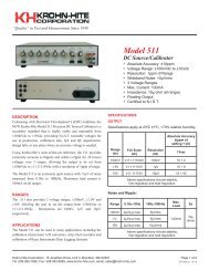
To achieve ac cess to the 120V/240V connections, remove the bottom cover and change the connections to the desired<br />
120V<br />
Bottom View<br />
240V<br />
voltage as shown in Fig ure<br />
2.1.<br />
Figure 2.1 Jumper Settings for 120V/240V Operation<br />
2-1
Section 2 - Operation<br />
Model <strong>3380</strong> Series<br />
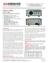
Model 3382 Filters<br />
Note: On early models, a 120V/240V switch was provided next to the Norm/Low line switch.<br />
120V<br />
240V<br />
Jumper<br />
120V<br />
240V<br />
Norm<br />
Low<br />
Line Switch<br />
In put<br />
Volt age<br />
Range<br />
(rms)<br />
Norm 108-132<br />
Low 90-110<br />
Norm 216-264<br />
Low 180-220<br />
In stall Fuse<br />
Model 3381 Model 3382 Model 3384<br />
.15A 1/4A 1/2A<br />
.1A 1/8A 1/4A<br />
120V/240V<br />
Jumper<br />
120V<br />
240V<br />
Power Con sump tion<br />
(watts)<br />
Model<br />
3381<br />
Model<br />
3382<br />
Model<br />
3384<br />
8 14 26<br />
9 16 30<br />
8 14 26<br />
9 16 30<br />
Set the 120V/240V and Norm/Low line switch and jump ers as needed according to the table above.<br />
Be sure to change the fuse to the proper rating for the line switch setting selected. Replace the cover.<br />
Plug the line cord into the unit, then the ac out let.<br />
After read ing the Self-Test feature, described next, turn on the Model <strong>3380</strong>.<br />
2-2
Model <strong>3380</strong> Series<br />
Section 2 - Operation<br />
2.3 SELF TEST<br />
When the Model <strong>3380</strong> is turned on, the microprocessor performs a self-test routine whereby the entire RAM and ROM<br />
operation is verified. If there is a malfunction, such as a defective RAM or ROM, the word “bad” will appear in the DIS -<br />
PLAY followed by a num ber 1 or 2. “bad 1” indicates U16, microprocessor is defective and a “bad 2” indicates U17,<br />
EPROM is defective.<br />
When the self-test program has completed, the Model <strong>3380</strong> will return to the setup stored in storage location 0. The<br />
Model <strong>3380</strong> is now ready for operation.<br />
2.4 OP ER A TION<br />
2.4.1 Front Panel Con trols and Dis play<br />
2.4.1.1 Chan nel Se lec tion (Mod els 3382 and 3384 only)<br />
The up [∆] control key below the CHANNEL display increments the channel number. The various dis plays and in di ca -<br />
tors on the front panel (cut off frequency, gains, etc.) per tain to the channel indicated by this dis play.<br />
2.4.1.2 Set ting Cut off Fre quency<br />
Data entry keys [0] to [9], [.], [KILO] and [MEGA] set the numeric value of the cut off fre quency desired. To se lect<br />
1.5kHz, press the [1][.][5] data keys and parameter keys [KILO] and [FREQ]. The cut off fre quency for the channel se -<br />
lected will be indicated in Hertz on the four digit DISPLAY (when [ALL CH] mode is selected, the frequency will be<br />
changed on all channels). The KILO and FREQ keys will be lit.<br />
2.4.1.3 Digit Se lect/Fre quency In cre ment and Dec re ment<br />
When the [SHIFT] key is pressed, followed by the DIGIT SELECT [∆] or [∇] keys, the FREQUENCY DISPLAY will<br />
intensify a digit. Pressing the [SHIFT] followed by the [∆] or [∇] key again, will intensify the next digit or will turn the<br />
DIGIT SELECT off. The [∆] will move the intensified digit to the left and the [∇] will move the intensified digit to the<br />
right (direction is labeled in red to the left of keys).<br />
Pressing the [∆] or [∇] keys will then increment or decrement the intensified frequency digit.<br />
2.4.1.4 Set ting In put Gain (Pre-Fil ter)<br />
Up [∆] and down [∇] INPUT GAIN SET controls increase or decrease the input amplifier by 10dB. The two digit DIS -<br />
PLAY will indicate either 0dB, 10dB 20dB, 30dB, 40dB or 50dB. May also be set by entering gain desired directly on<br />
the keypad and pressing either the [∆] or [∇] gain key.<br />
2.4.1.5 Set ting Out put Gain (Post Fil ter)<br />
Up [∆] and down [∇] OUTPUT GAIN SET controls increase or decrease the output amplifier by 0.1dB steps from 0dB<br />
to 20.0dB. For gains 10dB, only 1dB res o lu tion is displayed; how ever,<br />
the up [∆] and down [∇] keys con tinue to increment and decrement the gain by 0.1dB. The full 3-digit resolution may be<br />
seen in the middle display by pressing [SHIFT] the [∆] or [∇] key un der the out put gain display. Also for gains >10dB,<br />
the decimal point is off for whole dB’s (10, 11, 12, etc.) but on for fractional (10.1 – 10.9, 11.1 – 11.9, etc.). Gain may<br />
also be set by entering gain desired directly on the key pad and pressing either the [∆] or [∇] gain key.<br />
2.4.1.6 Butterworth or Bessel Se lec tion – [TYPE]<br />
When [TYPE] is pressed once, DISPLAY indicates the present filter type, “bu.” (Butterworth) and “bES.” (Bessel).<br />
When pressed again, the type will change (i.e. if the type was “bES.” , the change will be to “bu.”.)<br />
2-3
Section 2 - Operation<br />
Model <strong>3380</strong> Series<br />
2.4.1.7 Low-Pass and High-Pass Op er a tion – [MODE]<br />
When [MODE] is pressed once, DISPLAY indicates the present filter type, “h.P.” (high-pass) and “L.P.” (low-pass).<br />
When pressed again, the type will change (if the type was “L.P.” , the change will be to “h.P.”).<br />
2.4.1.8 Vari able Band-Pass Op er a tion (Mod els 3382 and 3384 only)<br />
To obtain Band-Pass operation with 48dB per oc tave attenuation proceed as follows:<br />
Set channel 1 to high-pass mode (this will control the low cut off frequency). Set channel 2 to low-pass (this will con trol<br />
the high cut off frequency). Connect the input signal to channel 1 input, connect the chan nel 1 output to the channel 2 in -<br />
put and connect the load to the channel 2 output. For the Model 3384, the same can be done with channels 3 and 4 respec -<br />
tively.<br />
The minimum pass-band is obtained by setting the high cutoff frequency equal to the low cut off frequency. In this condi -<br />
tion the insertion loss is nominally 6dB (in the Butterworth mode) and the –3dB cut off fre quencies occur at 0.8 and 1.25<br />
times the mid-band frequency. Insertion loss may be made-up by setting out put gains to +6dB.<br />
2.4.1.9 Vari able Band-Re ject Op er a tion (Mod els 3382 and 3384 only)<br />
To obtain Band-Reject or Notch operation, proceed as follows:<br />
Connect the two channels in parallel by connecting the input signal to the in put of each channel simultaneously. The out -<br />
put from both channels should be added through two equal external resistors in series with each output. The junction of<br />
these resistors becomes the output of the filter. It is recommended that the resistors be approximately 1k ohms and of the<br />
carbon or metal film type if the filter is used at higher frequencies. If the two resistors are not equal, the gain on one side<br />
of the notch will be different than the gain of the other. Insertion loss may be made-up by setting out put gains to +6dB.<br />
Set channel 1 for low-pass and channel 2 for high-pass, and adjust the cut off of each channel for the maximum re jec tion.<br />
The ideal notch occurs when setting the low cut off (low-pass) to 0.5 and the high cutoff (high-pass) to 1.5 notch. In ser -<br />
tion loss may be made-up by setting out put gains to +6dB.<br />
Caution: Do not exceed specified voltage at terminals.<br />
2.4.1.10 AC/DC Cou pling<br />
Pressing the [SHIFT] key, followed by the [TYPE] key, will display the present in put coupling, indicating “AC” or<br />
“dC”. Press [SHIFT] [TYPE] again to toggle between AC and DC.<br />
2.4.1.11 Dif fer en tial/Sin gle-Ended In put<br />
LED indicators are provided on the front panel to indicate which in put(s) is (are) active. Pressing [SHIFT] and then the<br />
[+ONLY] key under the In put Gain Display will select single-ended input mode, only the LED beside the +In put of the<br />
selected channel will be lit. Pressing [SHIFT] and then the [DIFF] key, will select the dif ferential in put mode and both<br />
LEDs beside the selected channel will be lit.<br />
2.4.1.12 Stor ing a Fil ter Setup – [STORE]<br />
There are 9 storage locations for storing front panel filter set ups. The locations are num bered 0 through 8. When<br />
[SHIFT] [RECLL][STORE] is first pressed, the DISPLAY indicates the number of the next mem ory location avail able.<br />
For example, the DISPLAY will indicate the following: “n=05”. Press ing [RECLL] again will store the entire filter<br />
set-up into that mem ory location. If another memory location is desired, enter that loca tion on the keyboard and then<br />
press [SHIFT] [RECLL].When [SHIFT] [RECLL] is preceded by a number (0-8), the <strong>3380</strong> will store the current filter<br />
set-up into the memory location selected.<br />
When [SHIFT] [RECLL] is pressed to indicate the next mem ory location only, press ing the clear entry key [CE] will re -<br />
store the DISPLAY to the cut off frequency setting. The filter settings stored in mem ory location 0 is automatically re -<br />
called at turn-on.<br />
2-4
Model <strong>3380</strong> Series<br />
Section 2 - Operation<br />
2.4.1.13 Re call ing a Fil ter Setup – [RECLL]<br />
When [RECLL] is preceded by a number, it will recall the filter set-up which was stored in the mem ory location selected.<br />
Selectable locations are 0 to 8.<br />
When first pressed, the DISPLAY in di cates the num ber of the mem ory lo ca tion to be re called. For ex am ple, the DIS -<br />
PLAY will indicate the following: “n=05”. Pressing the [RCLL] key again will recall the entire filter set-up from mem -<br />
ory location “05”.<br />
When pressed to indicate the memory location to be recalled only, press ing the [CE] (clear entry key) will restore the<br />
DISPLAY to the cutoff frequency set ting.<br />
Memory location 0 is automatically recalled at turn-on.<br />
2.4.1.14 Clear En try Key – [CE]<br />
When en ter ing a numeric value in the keyboard, but not specifying a parameter, pressing the clear entry key will re store<br />
the DISPLAY to the current cutoff frequency set ting.<br />
When a numeric value and its parameter has been entered and the numeric value is then changed, press ing the [CE] key<br />
will restore DISPLAY to the pre vi ous value of that parameter. Pressing the [CE] key contin uously will toggle between<br />
the previous keypad entry and the present entry.<br />
When either the [STORE] or [RECALL] key is pressed, the next memory location will be indicated on the DISPLAY.<br />
Pressing the [CE] key will restore DISPLAY to the current cutoff frequency set ting.<br />
2.4.1.15 All Chan nel Mode – [ALL CH] (Mod els 3382 and 3384)<br />
When [ALL CH] is pressed, the LED in the [ALL CH] key will light; and when frequency, input/output gain, type, mode,<br />
+only or diff input, and/or coupling is entered or changed, the new setting will be entered in all channels of the filter.<br />
2.5 REAR PANEL DC LEVEL ADJ.<br />
The Model <strong>3380</strong> rear panel has 2, 4 or 8 output dc level adjustments. The following pro ce dure is for adjusting the out put<br />
dc level to zero volts for any chan nel.<br />
2.5.1 DC Level Adj. (Rear Panel) HP<br />
Set the filter to HP at 1.1kHz. Ad just HP for 0V at filter output.<br />
2.5.2 DC Level Adj (Rear Panel) Out<br />
At any frequency setting, the output dc level may be adjusted to zero volts for each channel with the rear panel, screw -<br />
driver adjust, out put dc level con trol.<br />
2-5
Section 2 - Operation<br />
Model <strong>3380</strong> Series<br />
2.6 FIL TER CHAR AC TER IS TICS<br />
2.6.1 Am pli tude Re sponse<br />
Each channel of the Model <strong>3380</strong> can operate in either the low-pass or high-pass mode at 48dB/oc tave attenuation and<br />
provide either maximally flat (Butterworth) amplitude response or linear phase (Bessel) op eration. Comparative ampli -<br />
tude response characteristics in both modes are shown in Figure 2.2A and 2.2B.<br />
Figure 2.2A Low-Pass Amplitude Response<br />
Figure 2.2B High-Pass Amplitude Response<br />
2.6.2 Phase Re sponse<br />
Phase characteristics of the Model <strong>3380</strong> is shown in Fig ure 2.3. The graph of the filter response provides out put phase<br />
relative to the input over a 10:1 frequency range.<br />
2-6
Model <strong>3380</strong> Series<br />
Section 2 - Operation<br />
Figure 2.3 Phase Response<br />
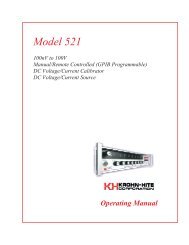
2.6.3 Group De lay<br />
Group delay 1 , shown in Figure 2.4, on opposite page, is defined as the derivative of radian phase with respect to radian<br />
frequency, which is the slope of the phase curve. A flat group delay is considered a linear phase response which corre -<br />
sponds to a constant slope of the phase curve. With linear phase re sponse, the dis tor tion of complex data signals will be<br />
minimized because their various frequency components, due to constant time delay, will not shift relative phase.<br />
In numeric terms, the zero frequency phase slope is –293.7°/Hz for Butterworth and –351.9°/Hz for Bessel, when normal -<br />
ized for a cutoff frequency of 1Hz. This will be 2π times greater in °/Hz for a cut off of 1 radian/sec or –1845°/Hz and<br />
–2211°/Hz respectively. Dividing by 360 converts °/Hz to radians/radians-per-sec yields a group delay time of 5.13s for<br />
Butterworth and 6.14s for Bessel.<br />
[1] IEEE Standard Dictionary of Electrical and Electronic Terms, Institute of Electrical and Electronic Engineers,<br />
IEEE-STD 100-1977, Second Edition, 1977, page 296. , shown in Figur , shown in Figur<br />
2-7
Section 2 - Operation<br />
Model <strong>3380</strong> Series<br />
2.6.4 Tran sient Re sponse<br />
The normalized response for a unit step voltage applied to the in put of the Model <strong>3380</strong> oper ating in the low-pass mode<br />
with both Butterworth and Bessel response is shown in Figure 2.5, on page 2-12.<br />
Figure 2.4 Group Delay<br />
2-8
Model <strong>3380</strong><br />
Section 3 - Incoming Acceptance<br />
SECTION 3<br />
INCOMING ACCEPTANCE<br />
3.1 IN TRO DUC TION<br />
The following procedure should be used to verify that the Model <strong>3380</strong> filter is operating within specifications. These checks<br />
may be used for incoming acceptance and periodic performance checks. Tests must be made with all covers in place and oper -<br />
ating for a minimum of 30 minutes to reach operating temperature. If the unit is not operating within specifications, refer to<br />
Calibration Section of the Maintenance <strong>Manual</strong> before attempting any detailed maintenance. Before testing, follow the initial<br />
set-up and operating procedure in Section 2.<br />
3.2 TEST EQUIP MENT RE QUIRED<br />
The test equipment below is required to perform the following tests:<br />
a. Low Distortion RC Oscillator: <strong>Krohn</strong>-<strong>Hite</strong> Model 4400A or equivalent.<br />
b. RC Oscillator: 10Hz to 10MHz, frequency response of ±0.025dB from 10Hz to 500kHz. <strong>Krohn</strong>-<strong>Hite</strong> Model 4300B or<br />
equivalent.<br />
c. AC Voltmeter: capable of measuring 100µV to 10Vrms, 10MHz bandwidth, Fluke Model 8920A or equivalent.<br />
d. Frequency Counter.<br />
e. Distortion Analyzer: <strong>Krohn</strong>-<strong>Hite</strong> Model 6900B or equivalent.<br />
If the [ALL CHAN] key is not lit, press the [ALL CHAN] key to<br />
turn on ALL CHANNEL mode. Perform each test on channel 1,<br />
then repeat it on channel 2.<br />
3.3 CUT OFF FRE QUENCY AC CU RACY<br />
Place BNC tees on the oscillator’s output and the filter’s `+’ input and set the filter’s input to `+ only’ (press [SHIFT] [∆ in put<br />
gain].<br />
3-1
Section 3 - Incoming Acceptance Model <strong>3380</strong><br />
Connect the frequency counter to the oscillator, the oscillator to the filter `+’ in put, and the AC meter to the filter input.<br />
Set the filter to butterworth with the `TYPE’ key, lowpass with the ‘MODE’ key, 0dB input gain, 0dB output gain and<br />
5kHz with the `FREQ’ key . Set the oscillator to 5kHz, 1VRMS. Set the meter to read 0dB (dB and REL mode on the<br />
Fluke 8920). Connect the meter to the filter output; ad just the oscillator frequency to get –3.01dB. The frequency on the<br />
counter should be 5kHz ±3%. Change the filter to highpass, ad just the oscillator frequency for –3.01dB; the counter<br />
should read 5kHz ±3%. Change the filter to lowpass mode, bessel type. Ad just the oscillator frequency for –12.6dB; the<br />
frequency on the counter should be 5kHz ±3%. Change the filter to highpass, adjust the oscillator frequency for<br />
–12.6dB; the counter should read 5kHz ±3%.<br />
Repeat the entire above procedure for 50Hz, 500Hz, 50kHz and 200kHz. It is im por tant to re-reference the voltmeter at<br />
each new frequency since the amplitude of the generator may change with changes in frequency.<br />
3.4 STOPBAND AT TEN U A TION<br />
Accurate stopband attenuation measurements require some simple precautions because of low level signals. The filter should<br />
be shielded with the top and bottom covers in place. BNC cable only should be used between oscillator, filter and voltmeter,<br />
and no other instruments should be connected.<br />
Set the oscillator to 7Vrms, 20kHz and connect it to the `+’ IN PUT with the filter set to a cut off frequency of 1kHz and 0dB<br />
of Input and Out put gain. Connect the OUTPUT through a 6kHz passive high-pass filter, as shown in Fig ure 3.1, to the<br />
ac voltmeter. (Fluke 8920 should have `low range en able’ pressed in).<br />
Set the filter to low-pass mode. The filter OUTPUT should be
Model <strong>3380</strong><br />
Section 3 - Incoming Acceptance<br />
Figure 3.2<br />
Passive 2MHz Low-Pass Filter<br />
3.6 NOISE CHECK<br />
Short the `+’ inputs of both filter channels and set the channel being tested to 0dB input gain, 0dB output gain, lowpass<br />
(mode key), butterworth (type key), DC coupled (press shift then type, if display shows `AC’ press shift type again; dis -<br />
play will show `DC’). Con nect a 2MHz lowpass, pas sive fil ter, shown in Fig 3.2, to the ac voltme ter and, using a short<br />
coax BNC ca ble, con nect it to the model <strong>3380</strong>’s output. Set the filter to 5kHz. Voltmeter reading should be 400µV or<br />
less. Set the filter to highpass (mode key). Voltmeter reading should be 400µV or less. Set the filter to 50kHz, lowpass.<br />
Voltmeter reading should be 400µV or less. Set the filter to highpass. Voltmeter read ing should be 400µV or less. Set in -<br />
put gain to 50dB and output gain to 20dB (press 20 and either of the out put gain arrows). Volt meter should read 80mV or<br />
less.<br />
3.7 COM MON MODE RE JEC TION<br />
Set the filter to low-pass, 20kHz cut off and differential in put by pressing the shift key, then the DIFF key under the IN -<br />
PUT GAIN display. Set the generator to 10kHz at 7Vrms. Connect the gen er a tor to the + and – inputs simultaneously.<br />
Connect the ac voltmeter to the filter output. Reading should be
Section 3 - Incoming Acceptance Model <strong>3380</strong><br />
3.9 AC/DC COU PLING CHECK<br />
Apply a 1Vdc signal to the INPUT of the fil ter. Set the filter to low-pass mode with 0dB In put and Output gain.<br />
In the DC COUPLED mode, the OUTPUT of the filter should be approximately 1Vdc and ap prox i mately 0Vdc in the<br />
AC COU PLED mode.<br />
3-4