Model 3988 Op Manual.vp - Krohn-Hite Corporation
Model 3988 Op Manual.vp - Krohn-Hite Corporation
Model 3988 Op Manual.vp - Krohn-Hite Corporation

Create successful ePaper yourself
Turn your PDF publications into a flip-book with our unique Google optimized e-Paper software.
<strong>Model</strong> <strong>3988</strong><br />
Butterworth/Bessel<br />
8-Pole Dual Channel Filter<br />
0.03Hz to 1MHz Cutoff Frequency Range<br />
0dB to 50dB Pre-Filter Gain in 10dB Steps<br />
0dB to 20dB Post-Filter Gain in 0.1dB Steps<br />
Serial No. ____________<br />
<strong>Op</strong>erating <strong>Manual</strong><br />
15 Jonathan Drive, Unit 4, Brockton, MA 02301 U.S.A.<br />
Tel: (508) 580-1660; Fax: (508) 583-8989<br />
www.krohn-hite.com; info@krohn-hite.com<br />
Copyright © 2003 <strong>Krohn</strong>-<strong>Hite</strong> <strong>Corporation</strong>.<br />
All rights reserved. Contents of this publication may not be reproduced<br />
in any form without the written permission of <strong>Krohn</strong>-<strong>Hite</strong> <strong>Corporation</strong>.<br />
Printed in USA - 4/03.
Service and Warranty<br />
<strong>Krohn</strong>-<strong>Hite</strong> Instruments are designed and manufactured in accordance with sound engineering<br />
practices and should give long trouble-free service under normal operating conditions. If your instrument<br />
fails to provide satisfactory service and you are unable to locate the source of trouble, contact<br />
our Service Department at (508) 580-1660, giving all the information available concerning the<br />
failure.<br />
DO NOT return the instrument without our written or verbal authorization to do so. After contacting<br />
us, we will issue a Return Authorization Number which should be referenced on the packing slip and<br />
purchase order. In most cases, we will be able to supply you with the information necessary to repair<br />
the instrument, avoiding any transportation problems and costs. When it becomes necessary to return<br />
the instrument to the factory, kindly pack it carefully and ship it to us prepaid.<br />
All <strong>Krohn</strong>-<strong>Hite</strong> products are warranted against defective materials and workmanship. This warranty<br />
applies for a period of one year from the date of delivery to the Original Purchaser. Any instrument<br />
that is found within the one year warranty period not to meet these standards, will be repaired<br />
or replaced. This warranty does not apply to electron tubes, fuses or batteries. No other warranty is<br />
expressed or implied.<br />
<strong>Krohn</strong>-<strong>Hite</strong> <strong>Corporation</strong> reserves the right to make design changes at any time without incurring<br />
any obligation to incorporate these changes in instruments previously purchased.<br />
Modifications to this instrument must not be made without the written consent of an authorized employee<br />
of <strong>Krohn</strong>-<strong>Hite</strong> <strong>Corporation</strong>.
Table of Contents<br />
TABLE OF CONTENTS<br />
1.0 GENERAL DESCRIPTION ---------------------------------------------------------------<br />
1.1 INTRODUCTION . . . . . . . . . . . . . . . . . . . . . . 1-1<br />
1.1.1 Functions . . . . . . . . . . . . . . . . . . . . . 1-1<br />
1.1.2 Filter Mode . . . . . . . . . . . . . . . . . . . . 1-1<br />
1.1.3 Amplifier Mode. . . . . . . . . . . . . . . . . . . 1-1<br />
1.1.4 General. . . . . . . . . . . . . . . . . . . . . . 1-2<br />
1.1.5 <strong>Op</strong>tions. . . . . . . . . . . . . . . . . . . . . . 1-2<br />
2.0 OPERATION ------------------------------------------------------------------------------------<br />
2.1 INTRODUCTION . . . . . . . . . . . . . . . . . . . . . . 2-1<br />
2.2 TURN-ON PROCEDURE . . . . . . . . . . . . . . . . . . . 2-1<br />
2.3 SELF TEST . . . . . . . . . . . . . . . . . . . . . . . . 2-1<br />
2.4 FRONT PANEL CONTROLS AND DISPLAY . . . . . . . . . . . . 2-1<br />
2.4.1 Data Keys and Display . . . . . . . . . . . . . . . . 2-1<br />
2.4.2 Parameter and Control Keys. . . . . . . . . . . . . . 2-1<br />
2.4.3 Channel Selection. . . . . . . . . . . . . . . . . . 2-2<br />
2.4.4 Cutoff Frequency . . . . . . . . . . . . . . . . . . 2-2<br />
2.4.5 Input Gain (Pre-Filter). . . . . . . . . . . . . . . . 2-2<br />
2.4.6 Output Gain (Post-Filter). . . . . . . . . . . . . . . 2-2<br />
2.4.7 Digit Select/Increment and Decrement . . . . . . . . . . 2-2<br />
2.4.8 Key Click Feature On/Off . . . . . . . . . . . . . . . 2-3<br />
2.5 REAR PANEL CONTROLS AND CONNECTORS . . . . . . . . . . 2-3<br />
2.5.1 Introduction . . . . . . . . . . . . . . . . . . . . 2-3<br />
2.5.2 BNC Connectors and Indicators . . . . . . . . . . . . 2-3<br />
2.5.2.1 Input Connectors . . . . . . . . . . . . . . . . 2-3<br />
2.5.2.2 Output Connectors . . . . . . . . . . . . . . . 2-3<br />
2.5.2.3 Indicators . . . . . . . . . . . . . . . . . . 2-3<br />
2.5.3 DC Level Adj (Rear Panel) . . . . . . . . . . . . . . 2-3<br />
2.5.4 Power . . . . . . . . . . . . . . . . . . . . . . 2-3<br />
2.5.5 GPIB Connector . . . . . . . . . . . . . . . . . . 2-3<br />
2.6 FILTER OPERATION . . . . . . . . . . . . . . . . . . . . 2-3<br />
2.6.1 INTRODUCTION . . . . . . . . . . . . . . . . . . 2-3<br />
2.6.2 Variable Band-Pass and Band-Reject <strong>Op</strong>eration . . . . . . 2-3<br />
2.6.2.1 Band-Pass . . . . . . . . . . . . . . . . . . 2-3<br />
2.6.2.2 Band-Reject . . . . . . . . . . . . . . . . . . 2-3<br />
2.6.3 Amplitude Response . . . . . . . . . . . . . . . . . 2-4<br />
2.6.4 Phase Response . . . . . . . . . . . . . . . . . . 2-4<br />
2.6.5 Group Delay . . . . . . . . . . . . . . . . . . . . 2-4<br />
2.6.6 Transient Response . . . . . . . . . . . . . . . . . 2-5<br />
i
Table of Contents<br />
3.0 IEEE-488 STD (GPIB) PROGRAMMING ------------------------------------------<br />
3.1 INTRODUCTION . . . . . . . . . . . . . . . . . . . . . . 3-1<br />
3.2 PRELIMINARY PROGRAMMING INFORMATION. . . . . . . . . . 3-1<br />
3.2.1 GPIB Primary Bus Address . . . . . . . . . . . . . . 3-1<br />
3.2.2 IEEE-488 Bus Interface Programming Connector. . . . . . 3-1<br />
3.3 ASCII DATA COMMANDS. . . . . . . . . . . . . . . . . . . 3-2<br />
3.3.1 Format . . . . . . . . . . . . . . . . . . . . . . 3-2<br />
3.3.2 Types of Data Commands . . . . . . . . . . . . . . . 3-2<br />
3.3.3 Table of ASCII Commands . . . . . . . . . . . . . . 3-2<br />
3.3.4 Examples . . . . . . . . . . . . . . . . . . . . . 3-3<br />
3.3.4.1 Example 1 . . . . . . . . . . . . . . . . . . 3-3<br />
3.3.4.2 Example 2 . . . . . . . . . . . . . . . . . . 3-3<br />
3.3.4.3 Example 3 . . . . . . . . . . . . . . . . . . 3-3<br />
3.4 IEEE-488 STANDARD COMMANDS . . . . . . . . . . . . . . . 3-4<br />
3.4.1 Multi-Line Messages. . . . . . . . . . . . . . . . . 3-4<br />
3.4.2 Polling Commands . . . . . . . . . . . . . . . . . 3-4<br />
3.4.2.1 Parallel Polling . . . . . . . . . . . . . . . . 3-4<br />
3.4.2.2 Service Request and Serail Polling . . . . . . . . . . 3-5<br />
3.4.2.3 Serial Responses . . . . . . . . . . . . . . . . 3-5<br />
3.4.3 Uniline Messages . . . . . . . . . . . . . . . . . . 3-6<br />
3.5 TALKER FORMAT . . . . . . . . . . . . . . . . . . . . . 3-11<br />
3.5.1 Parameter Information Format . . . . . . . . . . . . 3-11<br />
3.5.2 Overload Status Information Format . . . . . . . . . . 3-11<br />
3.5.3 <strong>Model</strong> Number and Software Version . . . . . . . . . . 3-11<br />
3.6 PROGRAMMING EXAMPLES . . . . . . . . . . . . . . . . . 3-12<br />
3.6.1 Example 1 – Microsoft Quick Basicß . . . . . . . . . . 3-12<br />
3.6.2 Example 2 – Borland Turbo C . . . . . . . . . . . . 3-12<br />
3.6.3 Example 3 – National Instruments IBIC . . . . . . . . 3-12<br />
4.0 INCOMING ACCEPTANCE --------------------------------------------------------------<br />
4.1 INTRODUCTION . . . . . . . . . . . . . . . . . . . . . . 4-1<br />
4.2 TEST EQUIPMENT REQUIRED . . . . . . . . . . . . . . . . 4-1<br />
4.3 CUTOFF FREQUENCY ACCURACY . . . . . . . . . . . . . . . 4-1<br />
4.4 STOPBAND ATTENTUATION . . . . . . . . . . . . . . . . . 4-1<br />
4.5 PRE-FILTER AND POST-FILTER GAIN ACCURACY . . . . . . . . 4-2<br />
4.6 NOISE CHECK . . . . . . . . . . . . . . . . . . . . . . . 4-2<br />
4.7 COMMON MODE REJECTION . . . . . . . . . . . . . . . . . 4-2<br />
4.8 DISTORTION AND MAXIMUM SIGNAL CHECKS. . . . . . . . . . 4-2<br />
4.9 AC/DC COUPLING CHECK . . . . . . . . . . . . . . . . . . 4-2<br />
ii
Table of Contents<br />
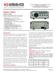
Figure 1 – <strong>Model</strong> <strong>3988</strong> Programmable Filter<br />
iii
Table of Contents<br />
i-vi
Section 1 - General Description<br />
SECTION 1<br />
GENERAL DESCRIPTION<br />
1.1 INTRODUCTION<br />
The <strong>Krohn</strong>-<strong>Hite</strong> <strong>Model</strong> <strong>3988</strong> Butterworth/Bessel dual channel filter is one of a family of filters carefully<br />
designed with the user in mind, providing ease of operation, reliability and price competitiveness.<br />
The <strong>3988</strong> provides a tunable frequency range from 0.03Hz to 1MHz in the low-pass mode and<br />
0.03Hz to 300kHz in the high-pass mode. Both modes are extended down to 0.003Hz with the 002<br />
option. The frequency response characteristic is either maximally flat (Butterworth) for clean filtering<br />
in the frequency domain, or linear phase (Bessel) to provide superior pulse or complex filtering<br />
is operator selectable.<br />
Each channel of the <strong>3988</strong> is an 8-pole, wide range, low-pass/high-pass filter or an amplifier providing<br />
gains to 70dB in 0.1dB steps. The <strong>3988</strong> will accept input signals of 10V peak at 0dB gain and<br />
has selectable ac or dc coupling. Overload detectors are standard and assist the user in detecting input<br />
signals or incorrect gain settings.<br />
Ninety-nine groups of non-volatile memory for storage of front panel set-ups, which are stored in<br />
battery-backed CMOS. Set-ups can then be recalled with a simple command.<br />
Band-pass operation is achieved by simply connecting the two channels in series.<br />
Applications of the <strong>Model</strong> <strong>3988</strong> are ultra-sound measurements, random noise testing, sound recording,<br />
suppressing interference in audio communications and related fields of medical, geological,<br />
geophysical, oceanographic, military and many more.<br />
1.1.1 FUNCTIONS (Each Channel)<br />
Low-pass filter, high-pass filter, voltage gain amplifier.<br />
1.1.2 FILTER MODE<br />
Type: 8-pole, Butterworth/Bessel.<br />
Attenuation: 48dB/octave.<br />
Tunable Frequency Range fc: Low-pass, 0.03Hz to 1MHz; high-pass, 0.03Hz to 300kHz; (option<br />
002, 0.003Hz).<br />
Frequency Resolution: 3 digits, 0.5Hz to max fc; 2 digits, 0.03Hz to 0.5Hz; (option 002, 3 digits,<br />
0.05Hz to 0.5Hz; 2 digits, 0.003Hz to 0.05Hz).<br />
1-1
Section 1 - General Description<br />
Cutoff Frequency Accuracy: ±1%, 0.5Hz to 50kHz; ±2%, 50.1kHz to max fc;<br />
±5%, 0.03Hz to 0.5Hz (option 002, ±5%, 0.003Hz to 0.5Hz).<br />
Relative Gain at fc: –3dB, Butterworth; –12.6dB, Bessel.<br />
High-Pass Bandwidth (0dB Gain): fc to 2.5MHz.<br />
Stopband Attenuation: >80dB.<br />
Insertion Loss: 0dB; ±0.2dB.<br />
Pre-Filter Gain: 0dB, 10dB, 20dB, 30dB, 40dB, 50dB; ±0.2dB.<br />
Post-Filter Gain: 0dB to 20dB in 0.1dB steps; ±0.2dB.<br />
Input Coupling: ac (0.16Hz) or dc.<br />
Wideband Noise (referred to input, 2MHz BW detector):<br />
min. gain, 60dB to 10kHz; >50dB to 99kHz.<br />
Sensitivity: 3mV peak with 70dB total gain for 10V peak output.<br />
Maximum Input: æ10V peak at 0dB gain, reduced in proportion to gain setting (to 500kHz LP).<br />
Impedance: 1 megohm in parallel with 100pf.<br />
Coupling: ac or dc.<br />
Maximum DC Component: ±100V in ac coupled mode.<br />
Output:<br />
Maximum Voltage (o.c.): 7Vrms to 200kHz; 3Vrms to 500kHz; 1Vrms to 1MHz.<br />
Impedance: 50 ohms.<br />
DC Offset: Adjustable to zero volts.<br />
Harmonic Distortion (1V output): –80dB (0.01%) to 10kHz; –60dB (0.1%) to 100kHz..<br />
Wideband Noise (referred to input, 2MHz BW detector): 250mVrms min. Gain;<br />
25mVrms max. gain.<br />
1-2
Section 1 - General Description<br />
DC Stability (RFI): Typically ±10mV/°C.<br />
Crosstalk Between Channels: >85dB below full scale with input source
Section 1 - General Description<br />
This page intentionally left blank.<br />
1-4
Section 2 - <strong>Op</strong>eration<br />
SECTION 2<br />
OPERATION<br />
2.1 INTRODUCTION<br />
The <strong>Model</strong> <strong>3988</strong> is a filter covering the frequency range from 0.03Hz (0.003Hz with option 002) to<br />
1MHz in low-pass mode and 300kHz in high-pass mode. All filter parameters are programmable via<br />
the front panel keyboard controls or remotely over the III-488 (GPIB) bus.<br />
The filter has three modes of operation: high-pass, low-pass and gain only. Each mode will be explained<br />
in detail in this section.<br />
2.2 TURN-ON PROCEDURE<br />
The <strong>Model</strong> <strong>3988</strong> line voltage range has been preset for either 115V or 230V operation. To change<br />
this setting, remove the bottom cover to expose the line switch. Be sure to change the fuse to the<br />
proper rating for the line switch setting selected.<br />
Make certain the POWER switch on the front panel is off.<br />
Plug the line cord into the unit, then the ac outlet.<br />
If the <strong>Model</strong> <strong>3988</strong> is to be programmed remotely, connect the bus cable to the rear panel connector of<br />
the <strong>3988</strong>.<br />
After reading the Self-Test feature, described next, turn on the <strong>Model</strong> <strong>3988</strong>.<br />
2.3 SELF TEST<br />
When the <strong>Model</strong> <strong>3988</strong> is turned on, the microprocessor performs a self-test routine whereby the entire<br />
RAM and ROM operation is verified. During the test, the front panel LEDs and DISPLAYS will<br />
light sequentially. If there is a malfunction on the microprocessor board, such as a defective RAM or<br />
ROM, the sequence will stop and the word “bad” will appear in the DISPLAY followed by a number<br />
1, 2 or 3. Refer to Section 6, Maintenance, to find which RAM or ROM is defective.<br />
When the self-test program is complete, the <strong>Model</strong> <strong>3988</strong> will return to the last set-up prior to turning<br />
the unit off. The <strong>Model</strong> <strong>3988</strong> is now ready to be programmed for operation.<br />
2-1
Section 2 - <strong>Op</strong>eration<br />
2.4 FRONT PANEL CONTROLS AND DISPLAY<br />
2.4.1 Data Keys And Display<br />
Data entry keyboard controls [0] to [9] and [.] set the numeric value of the parameter selected. To enter<br />
1.5kHz press the [1][.][5] keys and the parameter key [KILO] and [FREQ]. The cutoff frequency<br />
will be indicated in the DISPLAY.<br />
2.4.2 Parameter And Control Key<br />
[KILO] - When pressed, multiplies the numeric value of the keyboard entry by 103.<br />
[MEGA] - When pressed, multiplies the numeric value of the keyboard entry by 106.<br />
[FREQ] - When pressed, enters and/or displays frequency in Hertz.<br />
[TYPE] - When pressed, DISPLAY indicates the filter type, “bu.” (Butterworth) and “bES.”<br />
(Bessel). When pressed again, the type will change (i.e. if the type was “bES.”, the change will be to<br />
“bu.”.<br />
[MODE] - When pressed, DISPLAYindicates the mode of operation for the channel displayed. “L.P<br />
- 1.” for low-pass, “h.P.” for high-pass and “GAin” for gain (amplifier mode).<br />
When pressed again, the MODE will change to the next in the order explained above.<br />
[RECLL] - When preceded by a number, it will recall the entire instrument set-up from the memory<br />
location selected.<br />
When first pressed, the DISPLAY indicates the number of the next memory location to be recalled.<br />
For example, the DISPLAY will indicate the following: “n=09”. Pressing the [RCLL] key again will<br />
recall the entire instrument set-up from memory location “09”.<br />
When pressed to indicate the next memory location to be recalled only, pressing the [CE] (clear entry<br />
key) will restore the DISPLAY to the cutoff frequency setting.<br />
[ALLCH] - When frequency, input/output gain, type, mode or coupling are entered or changed, and<br />
the LED in the [ALL CH] key is lit, the new setting will be entered in both channels of the filter.<br />
[SHIFT] - The [SHIFT] key in conjunction with other keys (keys with red lettering under them) provide<br />
additional filter characteristics, and permits front panel entry of the type of GPIB line termination<br />
and address.<br />
Store - When [SHIFT] [RECLL] is first pressed, the DISPLAY indicates the number of the next<br />
memory location available. For example, the DISPLAY will indicate the following: “n=09”.<br />
Pressing [RECLL] again will store the entire instrument set-up into that memory location. If another<br />
memory location is desired, enter that location on the keyboard and then press [SHIFT] [RECLL].<br />
When [SHIFT] [RECLL] is preceded by a number (0-98), the filter will store the entire instrument<br />
set-up into the memory location selected. The maximum number of memory groups is 99.<br />
When [SHIFT] [RECLL] is pressed to indicate the next memory location only, pressing the clear entry<br />
key [CE] will restore the DISPLAY to the cutoff frequency setting.<br />
AC/DC Coupling - Pressing the [SHIFT] key followed by the [TYPE] key will display the input coupling,<br />
indicating “AC” or “dC”, and will alternate between the two when in the low-pass and gain<br />
modes. High-pass mode will indicate “AC” only.<br />
2-2
Section 2 - <strong>Op</strong>eration<br />
GPIB Address - When the [SHIFT] key followed by the [MEGA] key are pressed, the DISPLAYwill<br />
indicate the existing GPIB address setting. To select a different address setting, enter the address<br />
number in the data keys from [0] to [30] and press the [SHIFT] followed by the [MEGA] key (see<br />
Section 3.2.1 for GPIB addressing information).<br />
GPIB Line Termination - When the [SHIFT] key followed by the [ALL CH] key are pressed, the<br />
DISPLAY will indicate the existing GPIB Line Termination Code sequence. To select a different<br />
one, enter a number from [0] to [4] and press [SHIFT] [ALL CH] keys (see Section 3.2.1 for line termination<br />
information).<br />
Software Version - When the [SHIFT] key followed by the [KILO] key are pressed, the DISPLAY<br />
will indicate the software version installed (i.e. 3.7).<br />
[CE] - When entering a numeric value in the keyboard, but not specifying a parameter, pressing the<br />
clear entry key will function as an error correction procedure and restore DISPLAY to the current<br />
cutoff frequency setting.<br />
When a numeric value and its parameter has been entered and the numeric value is then changed,<br />
pressing the [CE] key will restore DISPLAY to the previous value of that parameter.<br />
When either the [STORE] or [RECALL] key is pressed, the next memory location will be indicated<br />
on the DISPLAY. Pressing the [CE] key will restore DISPLAY to the current cutoff frequency setting.<br />
If the <strong>Model</strong> <strong>3988</strong> is operating via the IEEE-488 bus (the front panel REMOTE LED is “on”), pressing<br />
the [CE] key will return unit to LOCAL operation.<br />
2.4.3 Channel Selection<br />
The up [D] control key below the CHANNEL display alternates the channel settings.<br />
2.4.4 Cutoff Frequency<br />
Data entry keyboard controls [0] to [9] and [.] set the numeric value of the cutoff frequency desired.<br />
To select 1.5kHz, press the [1][.][5] data keys and parameter keys [KILO] and [FREQ]. The cutoff<br />
frequency for the channel selected will be indicated in Hertz on the four digit DISPLAY(when [ALL<br />
CH] mode is selected, the frequency will be changed on both channels). The KILO and FREQ keys<br />
will be lit. Also see 2.4.7.<br />
2.4.5 Input Gain (Pre-Filter)<br />
Up [] and down [] INPUT GAIN SET controls increase or decrease the input amplifier by 10dB.<br />
The two digit DISPLAY will indicate either 0dB, 10dB 20dB, 30dB, 40dB or 50dB.<br />
2.4.6 Output Gain (Post Filter)<br />
Up [] and down [] OUTPUT GAIN SET controls increase or decrease the output amplifier by<br />
0.1dB steps from 0dB to 20.0dB. For gains 10dB,<br />
only 1dB resolution is displayed; however, the up []and down [] keys continue to increment and<br />
decrement the gain by 0.1dB. The full 3-digit resolution may be seen in the middle display by pressing<br />
[SHIFT] the the [D] key under the output gain display. Also for gains >10dB, the decimal point is<br />
off for whole dB’s (10, 11, 12, etc.) but on for fractional (10.1 – 10.9, 11.1 – 11.9, etc.).<br />
2-3
Section 2 - <strong>Op</strong>eration<br />
2.4.7 Digit Select/Increment and Decrement<br />
When the [SHIFT] key is pressed, followed by the DIGIT SELECT []or[] keys, the DISPLAY<br />
will intensify the first or second digit. Pressing the [SHIFT] followed by the []or[] key again, will<br />
intensify the next digit or will turn the DIGIT SELECT off. Pressing the []or[] keys will then increment<br />
or decrement the desired intensified digit.<br />
Pressing [SHIFT] and either the []or[] keys again will intensify the next digit in the DISPLAY.<br />
The [] will move the intensified digit to the left and the [] will move the intensified digit to the<br />
right (direction is labeled in red to the left of keys).<br />
2.4.8 Key Click Feature On/Off<br />
When the [SHIFT] key is pressed, followed by the [] key under the CHANNEL display, the key<br />
click feature will either toggle on or off.<br />
2.5 REAR PANEL CONTROLS AND CONNECTORS<br />
2.5.1 Introduction<br />
The <strong>Model</strong> <strong>3988</strong> rear panel consists of the following: four input and two output BNC connectors, dc<br />
level adjustments, a fuse holder, GPIB bus connector and an ac receptacle.<br />
2.5.2 BNC Connectors and Indicators<br />
2.5.2.1 Input Connectors<br />
The <strong>Model</strong> <strong>3988</strong> has four input BNC connectors on both the front and rear panels. The inputs are labeled<br />
on the front panel CH1+, CH1–, CH2+ and CH2–; the rear panel is simply labeled – and +.<br />
NOTE<br />
A slide switch is provided on the rear panel for<br />
selecting the INPUT BNC connector desired.<br />
The selections are +, DIFF and –. The + is a<br />
non-inverting input, the – input is inverting and<br />
DIFF is for differential operation.<br />
2.5.2.2 Output Connectors<br />
The <strong>Model</strong> <strong>3988</strong> has two output BNC connectors on both the front and rear panels.<br />
2.5.2.3 Indicators<br />
Four LED indicators are provided on the front panel to indicate which input is active. A slide switch<br />
located on the rear panel selects the desired input.<br />
2-4
Section 2 - <strong>Op</strong>eration<br />
2.5.3 DC Level Adj (Rear Panel)<br />
Proper procedure for adjusting input and output dc levels can be found in the Calibration section of<br />
this manual.<br />
The two DC LEVELpotentiometers located on the rear panel of the <strong>Model</strong> <strong>3988</strong> are for adjusting the<br />
DC level at the output BNC connector.<br />
2.5.4 Power<br />
Receptacle: Standard 3 pin.<br />
Fuse: 1 2 amp slow-blow for 120V operation; 1 4 amp slow-blow for 230V operation. To change this<br />
setting, refer to section 2.2.<br />
2.5.5 GPIB Connector<br />
Standard IEEE-488 interface. Subsets are SH1, AH1, T6, L4, SR1, RL1, PP1, DC1, DT0, C0 and E1.<br />
2.6 FILTER OPERATION<br />
2.6.1 Introduction<br />
The <strong>Model</strong> <strong>3988</strong> is a filter with two identical channels that can function independently. Each channel<br />
is an 8-pole filter which can be either low-pass, high-pass or gain-only. Each can be either<br />
Butterworth of Bessel response type.<br />
2.6.2 Variable Band-Pass and Band-Reject <strong>Op</strong>eration<br />
2.6.2.1 Band-Pass<br />
Variable band-pass response is obtained by connecting the output of channel 1 to the +input of channel<br />
2 (with channel 2 differential switch set to “+”). Apply the signal to the input(s) of channel 1; the<br />
output signal will be at the channel 2 output BNC connector. Set channel 1 to high-pass and channel<br />
2 to low-pass. Enter the lower cutoff frequency to channel 1 and the higher cutoff to channel 2.<br />
2.6.2.2 Band-Reject<br />
Variable band-reject response is obtained by connecting the inputs in parallel; and the outputs in series<br />
through a band-reject kit (BR-30). Apply the signal to the input of channel 1; the output signal<br />
will be at the output of the BR-30 kit. Set channel 1 to low-pass and channel 2 to high-pass. Set the<br />
desired cutoff frequencies.<br />
2-5
Section 2 - <strong>Op</strong>eration<br />
2.6.3 Amplitude Response<br />
Each channel of the <strong>Model</strong> <strong>3988</strong> can operate in either the low-pass or high-pass mode at 48dB/octave<br />
attenuation and provide either maximally flat (Butterworth) amplitude response or linear phase<br />
(Bessel) operation. Comparative amplitude response characteristics in both modes are shown in Figure<br />
2.1A and 2.1B.<br />
Figure 2.1A Low-Pass Amplitude Response<br />
Figure 2.1B High-Pass Amplitude Response<br />
2-6
Section 2 - <strong>Op</strong>eration<br />
2.6.4 Phase Response<br />
Phase characteristics of the <strong>Model</strong> <strong>3988</strong> is shown is Figure 2.2. The filter provides output phase relative<br />
to the input over a 10:1 frequency range.<br />
Figure 2.2 Phase Response<br />
2.6.5 Group Delay<br />
Group delay 1 , shown in Figure 2.3, is defined as the derivative of radian phase with respect to radian<br />
frequency, which is the slope of the phase curve. A flat group delay is considered a linear phase response<br />
which corresponds to a constant slope of the phase curve. With linear phase response, the distortion<br />
of complex data signals will be minimized because their various frequency components, due<br />
to constant time delay, will not shift relative phase.<br />
In numeric terms, the zero frequency phase slope is –293.7º/Hz for Butterworth and –351.9°/Hz for<br />
Bessel, when normalized for a cutoff frequency of 1Hz. This will be 2 times greater in º/Hz for a<br />
cutoff of 1 radian/sec or –1845º/Hz and –2211º/Hz respectively. Dividing by 360 converts º/Hz to<br />
radians/radians-per-sec yields a group delay time of 5.13s for Butterworth and 6.14s for Bessel.<br />
2.6.6 Transient Response<br />
The normalized response for a unit step voltage applied to the input of the <strong>Model</strong> <strong>3988</strong> operating in<br />
the low-pass mode with both Butterworth and Bessel response is shown in Figure 2.4.<br />
[1] \i IEEE Standard Dictionary of Electrical and Electronic Terms\plain \f1 , Institute of Electrical and Electronic<br />
Engineers, IEEE-STD 100-1977, Second Edition, 1977, page 296.<br />
2-7
Section 2 - <strong>Op</strong>eration<br />
Figure 2.3<br />
Group Delay<br />
Figure 2.4<br />
Transient Response<br />
2-8
Section 3 - IEEE-488 STD (GPIB) Programming<br />
SECTION 3<br />
IEEE-488 STD (GPIB)<br />
PROGRAMMING<br />
3.1 INTRODUCTION<br />
The <strong>Model</strong> <strong>3988</strong> remote programming interface accepts both ASCII data commands and IEEE-488<br />
standard commands (ATN true) for control of the unit.<br />
In presenting the information required to program the <strong>Model</strong> <strong>3988</strong> via the IEEE-488 STD bus, this<br />
manual presupposes a user knowledge of both ASCII data and IEEE-488 bus commands.<br />
3.2 PRELIMINARY PROGRAMMING INFORMATION<br />
3.2.1 GPIB Primary Bus Address<br />
The GPIB primary address and software line-termination-character-sequence (LTCS) selection is<br />
set via the front panel keyboard as listed in Tables 3.1 and 3.2. These two parameters are stored in<br />
non-volatile memory and will be remembered indefinitely, even when the power to the unit is removed.<br />
They do not need to be reentered each time the unit is turned on.<br />
The LTCS affects the GPIB in the TALKER mode only (data output from the <strong>3988</strong> to the GPIB). After<br />
the printable characters have been sent, non-printable characters, such as carriage return (CR)<br />
and line feed (LF), are often required to achieve the desired results in various computers. Table 3.2<br />
lists the various key sequences with the LTCS it selects.<br />
SETTING AND DISPLAYING<br />
THE GPIB PRIMARY ADDRESS<br />
Function<br />
Keyboard Entry<br />
a. To set a primary address from 0 to 30 [X][SHIFT][MEGA]<br />
b. To display the primary address [SHIFT][MEGA]<br />
3-1
Section 3 - IEEE-488 STD (GPIB) Programming<br />
LINE-TERMINATION-CHARACTER-SEQUENCE<br />
Line-Termination Character-Sequence<br />
Keyboard Entry<br />
a. None (EOI only) [0][SHIFT] [ALLCH]<br />
b. Carriage return (with EOI) [1][SHIFT] [ALLCH]<br />
c. Line Feed (with EOI) [2][SHIFT] [ALLCH]<br />
d. Carriage return followed by line feed (with EOI) [3][SHIFT] [ALLCH]<br />
e. Line feed followed by carriage return (with EOI) [4][SHIFT] [ALLCH]<br />
f. Display present LTCS [SHIFT] [ALL CH]<br />
3.2.2 IEEE-488 Bus Interface Programming Connector<br />
The rear panel programming connector, labeled “IEEE-488 PORT” (Figure 3.1), is the standard bus<br />
interface connector as specified in the IEEE-488 STD.<br />
Figure 3.1<br />
Rear Panel GPIB Connector<br />
3-2
Section 3 - IEEE-488 STD (GPIB) Programming<br />
3.3 ASCII DATA COMMANDS<br />
3.3.1 Format<br />
The <strong>Model</strong> <strong>3988</strong> employs free-format software commands, allowing the user to program a specific<br />
function in several different ways. See Section 3.3.3.<br />
3.3.2 Types Of Data Commands<br />
a. Commands fall into two types : Those involving numeric parameters and those that do not.<br />
Commands which involve numeric data contain (3) types of fields:<br />
1. Numeric: Numeric fields may be floating point or scientific notation.<br />
1 = 1.0<br />
1.0 = 1.0<br />
2.7E3 = 2.7 X 10³<br />
–2E3 = –2 X 10³<br />
2E–3 = 2 X 10⁻³<br />
2. Multiplier: “KILO”, “MEGA”.<br />
3. Parameter: Parameter (frequency, gain, channel, etc.) is included in Section 3.3.3.<br />
b. Delimiters which may separate commands are the following: (; : / \ .)<br />
c. Two consecutive character strings (i.e. parameter and multiplier) must have a space between<br />
them or they will be treated as one string.<br />
d. The <strong>Model</strong> <strong>3988</strong> uses an internal 32 character buffer for command processing. A line may be<br />
composed of multiple commands, separated by delimiters mentioned above. No commands are<br />
executed until the line is terminated with a line feed ASCII character (Hex 0A) or carriage return<br />
(Hex 0D) or by sending the end-or-identify (EOI) command with the last character.<br />
3.3.3 Table Of ASCII Commands<br />
In this Section there are characters that are underlined and characters that are NOT underlined. The<br />
characters that are underlined MUST be sent for the command to be recognized properly. Any additional<br />
characters may be sent once all the underlined letters are sent. Commands are case sensitive;<br />
upper case characters MUST be used.<br />
3-3
Section 3 - IEEE-488 STD (GPIB) Programming<br />
MODEL <strong>3988</strong> GPIB COMMANDS<br />
Command Desired<br />
Allowable Character String<br />
Input Gain<br />
Frequency<br />
Channel<br />
Output Gain<br />
Type<br />
Mode<br />
Coupling<br />
IG<br />
IU<br />
ID<br />
F<br />
H<br />
K<br />
ME<br />
CH<br />
CU<br />
CD<br />
OG<br />
OU<br />
OD<br />
TY1<br />
TY2<br />
M1<br />
M2<br />
M3<br />
AC<br />
D<br />
set input gain<br />
increase input gain (up)<br />
decrease input gain (down)<br />
frequency<br />
frequency (Hz)<br />
kilo (103 multiplier)<br />
Mega (106 multiplier)<br />
set channel<br />
next channel (up)<br />
previous channel (down)<br />
set output gain<br />
increase output gain (up)<br />
decrease output gain (down)<br />
Butterworth<br />
Bessel<br />
low-pass<br />
high-pass<br />
gain only<br />
ac coupled<br />
dc coupled<br />
Store ST store<br />
Recall R recall<br />
All Channel<br />
AL<br />
B<br />
all channel mode<br />
NOT all channel mode<br />
3-4
Section 3 - IEEE-488 STD (GPIB) Programming<br />
Misc<br />
CE<br />
OV<br />
Q<br />
SRQON<br />
SRQOF<br />
V<br />
clear entry<br />
overflow (1, 2, 3)<br />
reports board model number(s) (see Section<br />
3.5.4)<br />
GPIB service request on<br />
GPIB service request off<br />
report model number and software version<br />
(see Section 3.5.3)<br />
Alphabetical Listing of <strong>Model</strong> <strong>3988</strong> GPIB Commands<br />
Character String<br />
Command<br />
AC<br />
ac coupled<br />
AL<br />
all channel mode<br />
B<br />
NOT all channel mode<br />
CD<br />
channel down<br />
CE<br />
clear entry<br />
CH<br />
channel # n<br />
CU<br />
channel up<br />
D<br />
dc coupled<br />
F<br />
frequency<br />
H<br />
frequency (Hz)<br />
ID<br />
input gain down<br />
IG<br />
input gain<br />
IU<br />
input gain up<br />
K<br />
kilo<br />
M1<br />
M2<br />
M3<br />
low-pass mode<br />
high-pass mode<br />
gain mode<br />
ME<br />
Mega (106 multiplier)<br />
OD<br />
output gain down<br />
OG<br />
output gain<br />
OU<br />
output gain up<br />
OV<br />
overflow mode<br />
Q report board model number(s) (see Section 3.5.4)<br />
R<br />
recall<br />
SRQON<br />
GPIB service request on<br />
SRQOF<br />
GPIB service request off<br />
ST<br />
store<br />
T1<br />
T2<br />
Butterworth Type<br />
Bessel Type<br />
V report model number and software version (see Section 3.5.3)<br />
3-5
Section 3 - IEEE-488 STD (GPIB) Programming<br />
3.3.4 Examples<br />
3.3.4.1 Example 1<br />
To set both channels to 10dB input gain, 2kHz, 0dB output gain:<br />
AL; 10IG;2K;0OG <br />
NOTE<br />
It is only necessary to send those parameters<br />
that change, all others remain unaffected.<br />
3.3.4.2 Example 2<br />
To change frequency to 150Hz:<br />
150H<br />
or 150bHZ†<br />
or 150F<br />
or .15K<br />
or F150<br />
or H150<br />
or HZ150<br />
or K0.15<br />
or 1.5E2HZ<br />
or F1.5E2<br />
3.3.4.3 Example 3<br />
To read back the settings of channel 2 (see Section 3.5.1):<br />
Data sent to filter: CH2<br />
Data received from filter † :10b2.000E+3b02b00bAC*<br />
Interpretation:<br />
10dB input gain<br />
2kHz cutoff frequency<br />
channel #2<br />
0dB output gain<br />
ac coupled<br />
all channel mode (indicated by the “*”)<br />
† \strike b\plain \ul \f1 represents a space<br />
3-6
Section 3 - IEEE-488 STD (GPIB) Programming<br />
3.4 IEEE-488 STANDARD COMMANDS<br />
These commands are sent with ATN true as described in the standard.<br />
3.4.1 Multi-Line Messages<br />
IEEE-488 Command Mnemonic Result<br />
My listen address MLA Enables unit to receive data.<br />
Unlisten UNL Disables unit from receiving data.<br />
My talk Address MTA Designates unit to send data.<br />
Untalk UNT Disables unit from sending data.<br />
Local lockout LLO Disables return-to-local key (CE key) on front panel<br />
such that when in remote mode, keyboard cannot be<br />
activated by pressing a front panel key.<br />
Go to local GTL Puts unit into local control mode such that front panel<br />
keyboard is activated.<br />
Device clear DCL When the device clear command is sent, the following<br />
parameters are changed regardless of their existing<br />
settings.<br />
Input Gain = 0dB<br />
Output Gain = 0dB<br />
Response = Butterworth<br />
Mode = Low-Pass<br />
Cutoff Frequency = 100kHz<br />
Coupling = ac Clears current settings for all channels.<br />
It does not clear set-ups stored with [STORE] key. It<br />
does not change interface bus parameters and flags,<br />
such as: addresses, SRQ ON/OFF, parallel poll bit selected,<br />
etc.<br />
Selected device clear SDC Performs same functions as device clear (DCL) except<br />
only if unit is addressed.<br />
DISCUSSION: (See Section 2.8 and Figure 10 of the IEEE-488 Interface Standard). Note that there<br />
are (4) possible states; local, remote, local-with-lockout, and remote-with-lockout. Front panel control<br />
is considered to be local while control from the system controller is considered to be remote. Selection<br />
of local or local-with-lockout and remote or remote-with-lockout is done several ways.<br />
When the unit is addressed to talk (MTA) or listen (MLA), it will enter into remote. When<br />
GO-TO-LOCAL (GTL) is sent, it enters into local mode or local-with-lockout mode.<br />
Also, if lockout mode is not invoked by the controller (local lockout command LLO), pressing the<br />
[CE] key when the remote LED is on will return control to the keyboard.<br />
3-7
Section 3 - IEEE-488 STD (GPIB) Programming<br />
NOTE<br />
The lockout mode is not related to whether control is<br />
local or remote, only whether control can be returned<br />
to local by the [CE] key.<br />
Lockout mode (local-with-lockout and remote-with-lockout versus local and remote) is controlled<br />
by the controller. Sending the local lockout command (LLO) selects the local-with-lockout and remote-with-lockout<br />
pair versus remote and local without lockout out. Lockout can only be canceled<br />
by the controller placing the remote enable line false.<br />
3.4.2 Polling Commands<br />
The IEEE standard provides two methods of determining the status of the devices in the system;<br />
namely serial poll and parallel poll. The parallel poll produces up to 8 bits of status from up to 8 different<br />
units simultaneously. A parallel poll is very fast but provides limited information. The serial<br />
poll provides 7 bits of status from one unit at a time.<br />
3.4.2.1 Parallel Polling<br />
The <strong>Model</strong> <strong>3988</strong> provides for software configuring of which bit and with which polarity the unit<br />
should respond. This bit is “true” when an error condition exists. (“ERR” displayed on the panel).<br />
Configuring needs to be done only once or anytime the software desires to change the configuration.<br />
The commands related to parallel poll are as follows:<br />
For sample sequences, see section 6.5.4 of the IEEE-488 standard.<br />
IEEE-488 Command Mnemonic Result<br />
Configure PPC Places unit into a state where it expects parallel poll enable<br />
and disable commands to establish which bits<br />
should be set or selected in response to a parallel poll.<br />
Unconfigure PPU Removes unit from PPC state (UNL does the same, but<br />
also unlistens device).<br />
Enable PPE When unit is in PPC state, it indicates which bit and<br />
which polarity the device should respond. Hex codes<br />
60-67 selects bits 0-7 respectively to be set to 0 for a<br />
true error response. Since logic 0 is HI on open collector<br />
lines, this provides a logical “OR” of all units designated<br />
to respond with a given line. Hex codes 68-6F selects<br />
bits 0-7 respectively to be set to 1 for a true (error)<br />
response. This can provide logical NAND of all units<br />
designated to respond with a given line.<br />
Disable PPD Clears any configuration previously entered. This is<br />
valid only when unit is in PPC state.<br />
3-8
Section 3 - IEEE-488 STD (GPIB) Programming<br />
Example: If the <strong>Model</strong> <strong>3988</strong> to be configured is unit #5, and we want it to respond with a “1” when an<br />
error exists:<br />
IEEE-488 Command Result<br />
MLA 5<br />
Addresses unit to be configured.<br />
PPC<br />
Places unit into parallel poll configured mode.<br />
PPE 8 Configures bit #0 (Lo 3 bits of command) to respond with a “1”<br />
(8’s bit) when an error exists.<br />
UNL<br />
Unlistens unit.<br />
For additional sample sequences, see Section 6.5.4 of the Standard.<br />
3.4.2.2 Service Request And Serial Polling<br />
The IEEE-488 standard provides serial polling as a method of determining which unit caused a service<br />
request. When serial poll enable (SPE) is sent, the system enters into serial poll state. When a<br />
unit is addressed to talk, a single status byte will be sent. The hex 40 bit in this byte is true if that unit<br />
is requesting service. The remaining bits are used to provide status information. The <strong>Model</strong> <strong>3988</strong><br />
service request capability is enabled or disabled with the SRQON and SRQOFF commands (see<br />
Section 3.3.3). The unit turns on with service request disabled. This is an extension of the standard.<br />
IEEE-488 Mnemonic Result<br />
Command<br />
Enable SPE Unit enters serial poll when a unit is addressed to talk. It will<br />
send one status byte in which the hex 40 bit is true if the unit is<br />
requesting service.<br />
Disable SPD Unit exists serial poll state.<br />
3.4.2.3 Serial Responses<br />
The chart below lists the error numbers, in decimal notation, resulting a command error either from<br />
the bus or not from the bus.<br />
The serial responses are:<br />
1. No error: 0.<br />
2. Error (error numbers in decimal notation); See the chart below.<br />
NOTE<br />
If SRQ is “ON” and the command which caused the<br />
error came from the bus, not the front panel, then the<br />
64 bit will be set in the serial poll response, indicating<br />
that this unit requires service.<br />
3-9
Section 3 - IEEE-488 STD (GPIB) Programming<br />
Error # Description<br />
1 Input gain too high or too low.<br />
2 Frequency too high.<br />
3 Frequency too low.<br />
4 Channel # too high.<br />
5 Channel # too low<br />
6 Output gain too high or too low.<br />
7 Store page # too high.<br />
8 Recall page # too high.<br />
9 Type # invalid.<br />
10 Mode # invalid.<br />
3.4.3 Uniline Messages<br />
IEEE-488 Command Mnemonic Result<br />
End END Sent with last byte of data. Aline of data may either<br />
be terminated by a line feed character or by this<br />
command.<br />
Identify IDY This command, issued by the controller, causes a<br />
parallel response which was previously configured<br />
by the PPC, PPD, PPE and PPU commands.<br />
Request service RQS Generated in response to an error when a command<br />
came from the bus, and service request is enabled<br />
by the SRQON command.<br />
Remote enable REN When true, allows the <strong>3988</strong> to respond to remote<br />
messages. When this line goes false, the unit will go<br />
to local-with-lockout state, activating the front<br />
panel.<br />
Interface clear IFC Un-addresses all units and clears all special states.<br />
3.5 TALKER FORMAT<br />
The Talker Software allows an IEEE-488 (GPIB) controller to interrogate the <strong>Model</strong> <strong>3988</strong> and read<br />
back over the bus it’s settings (gain, frequency, etc.)<br />
Four different types of data can be sent over the bus: Normally parameter information is returned unless<br />
an “OS”, “Q” or “V” command is sent to the unit.<br />
3-10
Section 3 - IEEE-488 STD (GPIB) Programming<br />
3.5.1 Parameter Information Format<br />
1. Two (2) digits of input gain.<br />
1a. space<br />
2. Four (4) digits plus decimal of frequency or other alpha.<br />
3. If frequency is displayed:<br />
E+0 if both kilo and mega LEDs are off<br />
E+3 if kilo LED is on<br />
E+6 if mega LED is on otherwise 3 spaces<br />
3a. space<br />
4. Two (2) digits, a decimal and one digit of channel #<br />
4a. space<br />
5. Two (2) digits of output gain<br />
5a. space<br />
6. “AC” if ac coupled<br />
“DC” if dc coupled<br />
7. “*” if all channel mode, otherwise a space (See Section 3.3.4.3 for example).<br />
3.5.2 OVERLOAD STATUS INFORMATION FORMAT<br />
After sending the “OS” command, the next line of data the <strong>3988</strong> sends will be four (4) characters; each character<br />
represents one channel.<br />
The character will be: “0” if not overloaded, “1” if input is overloaded, “2” if output is overloaded, “3” if both input<br />
and output are overloaded. The first character is channel 1, followed by channel 2. Channels which are not<br />
present return “0”.<br />
This data is returned only once per command; after that it returns to talking what the front panel is showing.<br />
3.5.3 <strong>Model</strong> Number and Software Version Format<br />
After sending the “V” command, the next line of data read from the <strong>Model</strong> <strong>3988</strong> will be as follows:<br />
KROHN-HITE V3.5<br />
The version number will reflect the revision level of the firmware in the instrument.<br />
This data is returned only once per command; after that it returns to talking what the front panel display<br />
is showing.<br />
3.6 PROGRAMMING EXAMPLES<br />
The following are programming examples in Microsoft® Quick Basic, Borland Turbo C and National<br />
Instruments IBIC.<br />
3.6.1 Example 1 – Microsoft Quick Basic<br />
3-11
Section 3 - IEEE-488 STD (GPIB) Programming<br />
‘ Microsoft (R) Quick Basic (tm) program for the <strong>Krohn</strong>-<strong>Hite</strong> <strong>Model</strong> <strong>3988</strong><br />
‘<br />
‘ * Enter this program from DOS by typing: QB <strong>3988</strong> /LQBIB.QLB<br />
‘ (the /L switch means tells Quick Basic to load a library)<br />
‘<br />
‘ * Set the instrument to GPIB address 1:<br />
‘ Press 1 [SECOND FUNCTION] [MEGA]<br />
‘<br />
‘ * Set the instrument for no carriage return or line feed (EOI only):<br />
‘ Press 0 [SECOND FUNCTION] [ALL CHAN]<br />
‘<br />
‘————— Initialize National Instruments Interface Board —————-<br />
‘<br />
‘$INCLUDE: ‘QBDECL.BAS’<br />
CLS<br />
CALL IBFIND(“GPIB0", BRD0%): ‘initialize access to the board<br />
CALL IBFIND(“DEV1", D<strong>3988</strong>%): ‘init access to the instrument, assumes addr 1!<br />
CALL IBTMO(D<strong>3988</strong>%, 10): ‘ set timeout to 300mS<br />
‘<br />
‘————————————- Send/receive the data —————————————<br />
‘<br />
‘ Set to 500 Hz (500HZ), 0dB input gain (0IG), 0db output gain (0OG),<br />
‘ DC coupled, re-display the frequency (F) so it will be read over the bus.<br />
CALL IBWRT(D<strong>3988</strong>%, “500HZ;0IG;0OG;DC;F”): IF IBSTA%
Section 3 - IEEE-488 STD (GPIB) Programming<br />
CALL IBCMD(BRD0%, “_”): IF IBSTA%
Section 3 - IEEE-488 STD (GPIB) Programming<br />
* * Set the instrument to GPIB address 1:<br />
* Press [1] [SECOND FUNCTION] [MEGA]<br />
*<br />
* * Set the instrument for no carriage return or line feed (EOI only):<br />
* Press [0] [SECOND FUNCTION] [ALL CHAN]<br />
*<br />
* This program assumes the name of the device at address 1 hasn’t been<br />
* changed in IBCONFIG (it’s still called DEV1, which is the default.)<br />
*<br />
* The status variables IBSTA, IBERR, and IBCNT are defined in DECL.H.<br />
* Each bit of IBSTA and each value of IBERR are defined in DECL.H as<br />
* a mnemonic constant for easy recognition in application programs. In<br />
* this example, these mnemonic definitions are logically ANDed with the<br />
* variable IBSTA to determine if a particular bit has been set. The mnemonic<br />
* definitions are equated with the variable IBERR to determine the error<br />
* code.<br />
*<br />
* The function GPIBERR is called when a NI-488 function fails. The<br />
* error message is printed along with the status variables IBSTA, IBERR,<br />
* and IBCNT.<br />
*<br />
* The NI-488 function IBONL is called from the main body of the program or<br />
* from the function GPIBERR. When the second parameter of the function<br />
* IBONL is zero, the software and hardware are disabled.<br />
* Execution of this program is terminated after the call to the function<br />
* IBONL to disable the software and hardware.<br />
*<br />
* The function EXIT is used to terminate this program within the function<br />
* GPIBERR. The exit status is set to 1 to indicate an error has occurred.<br />
*<br />
*/===================================================================<br />
*/<br />
#include <br />
#include <br />
3-14
Section 3 - IEEE-488 STD (GPIB) Programming<br />
#include <br />
/* DECL.H contains constants, declarations, and function prototypes. */<br />
#include “decl.h”<br />
#define DEVNUM “dev1" /* Set instrument to GPIB address 1 */<br />
/* GPIBERR is an error function that is called when a NI-488 function fails. */<br />
void gpiberr(char *msg);<br />
char rd[255]; /* read data buffer */<br />
int GpibDev,GpibBoard; /* device handles */<br />
void main() {<br />
printf(“\nSending data to the <strong>Krohn</strong>-<strong>Hite</strong> model <strong>3988</strong>...\n”);<br />
printf(“\n”);<br />
/*<br />
* Assign a unique identifier (a ‘handle’) to the K-H <strong>3988</strong> and store it in the<br />
* variable GpibDev. If GpibDev is less than zero, call GPIBERR with an error<br />
* message.<br />
*/<br />
GpibDev = ibfind (DEVNUM);<br />
if (GpibDev
Section 3 - IEEE-488 STD (GPIB) Programming<br />
* Clear the K-H <strong>3988</strong> to its default state. The settings vary depending on the<br />
* type of board in each channel. These settings are listed in the GPIB<br />
* section of the manual for each filter board (not the <strong>3988</strong> manual).<br />
* If the error bit ERR is set in IBSTA, call GPIBERR with an error message.<br />
*/<br />
ibclr (GpibDev);<br />
if (ibsta & ERR) gpiberr(“ibclr Error”);<br />
/*<br />
* Write a string out to the K-H <strong>3988</strong>.<br />
* If the error bit ERR is set in IBSTA, call GPIBERR with an error message.<br />
*/<br />
ibwrt (GpibDev,"500HZ;0IG;0OG;DC;F",18L); /* the ‘F’ displays the frequency so when*/<br />
if (ibsta & ERR) gpiberr(“ibwrt Error”); /* we read the unit we’ll see the freq */<br />
/*<br />
* Read the K-H <strong>3988</strong>. If the error bit ERR is set in IBSTA, call GPIBERR with<br />
* an error message.<br />
*/<br />
ibrd (GpibDev,rd,30L);<br />
if (ibsta & ERR) gpiberr(“ibrd Error”);<br />
/* Append the null character to mark the end of the data */<br />
rd[ibcnt] = ‘\0’; /* do this BEFORE calling ibcmd because ibcnt will be */<br />
printf(“Read: %s\n”, rd); /* changed by any ‘ib’ calls. */<br />
ibcmd(GpibBoard,"_",2L); /* send unt, unl */<br />
if (ibsta & ERR) gpiberr(“ibcmd Error”);<br />
/*<br />
* Change the K-H <strong>3988</strong> setting<br />
*/<br />
ibwrt (GpibDev,"333HZ;20IG;20OG;AC;F", 20L); /* the ‘F’ displays the frequency so when*/<br />
if (ibsta & ERR) gpiberr(“ibwrt Error”); /* we read the unit we’ll see the freq */<br />
3-16
Section 3 - IEEE-488 STD (GPIB) Programming<br />
/*<br />
* Read the K-H <strong>3988</strong> again like before.<br />
*/<br />
ibrd (GpibDev,rd,30L);<br />
if (ibsta & ERR) gpiberr(“ibrd Error”);<br />
rd[ibcnt] = ‘\0’;<br />
printf(“Read: %s\n”, rd);<br />
ibcmd(GpibBoard,"_",2L); /* send unt, unl */<br />
if (ibsta & ERR) gpiberr(“ibcmd Error”);<br />
/* Call the ibonl function to disable the hardware and software. */<br />
ibonl (GpibDev,0); /* Release the device handle */<br />
ibonl (GpibBoard,0); /* Release the board handle */<br />
exit(0); /* exit with no error */<br />
} /* main */<br />
/*==================================================================<br />
* Function GPIBERR<br />
* This function will notify you that a NI-488 function failed by<br />
* printing an error message. The status variable IBSTA will also be<br />
* printed in hexadecimal along with the mnemonic meaning of the bit position.<br />
* The status variable IBERR will be printed in decimal along with the<br />
* mnemonic meaning of the decimal value. The status variable IBCNT will<br />
* be printed in decimal.<br />
*<br />
* The NI-488 function IBONL is called to disable the hardware and software.<br />
*<br />
* The EXIT function will terminate this program.<br />
*===================================================================<br />
3-17
Section 3 - IEEE-488 STD (GPIB) Programming<br />
*/<br />
void gpiberr(char *msg) {<br />
unsigned int i;<br />
/* Table of ibsta (interface board status word) bit positions and<br />
corresponding messages */<br />
static struct { int bit; char *msg;} ibstaMsg[16]=<br />
{ {ERR, “ ERR”},<br />
{TIMO, “ TIMO”},<br />
{END, “ END”},<br />
{SRQI, “ SRQI”},<br />
{RQS, “ RQS”},<br />
{SPOLL," SPOLL"},<br />
{EVENT," EVENT"},<br />
{CMPL, “ CMPL”},<br />
{LOK, “ LOK”},<br />
{REM, “ REM”},<br />
{CIC, “ CIC”},<br />
{ATN, “ ATN”},<br />
{TACS, “ TACS”},<br />
{LACS, “ LACS”},<br />
{DTAS, “ DTAS”},<br />
{DCAS, “ DCAS”}};<br />
/* Table of iberr error messages */<br />
static struct { int val; char *msg;} iberrMsg[15]=<br />
{ { EDVR," EDVR \n"},<br />
{ ECIC," ECIC \n"},<br />
{ ENOL," ENOL \n"},<br />
{ EADR," EADR \n"},<br />
{ EARG," EARG \n"},<br />
{ ESAC," ESAC \n"},<br />
3-18
Section 3 - IEEE-488 STD (GPIB) Programming<br />
{ EABO," EABO \n"},<br />
{ ENEB," ENEB \n"},<br />
{ EOIP," EOIP \n"},<br />
{ ECAP," ECAP \n"},<br />
{ EFSO," EFSO \n"},<br />
{ EBUS," EBUS \n"},<br />
{ ESTB," ESTB \n"},<br />
{ ESRQ," ESRQ \n"},<br />
{ ETAB," ETAB \n"}};<br />
printf (“%s\n”, msg); /* Print the application supplied context message. */<br />
/*<br />
* The ibsta variable provides the primary information about the cause of<br />
* the error: print it’s value and mnemonic for each bit set.<br />
*/<br />
printf (“ibsta = &H%x
Section 3 - IEEE-488 STD (GPIB) Programming<br />
ibonl (GpibDev,0); /* Release the device handle */<br />
ibonl (GpibBoard,0); /* Release the board handle */<br />
exit(1); /* exit with status=1 to indicate error */<br />
3-20
3.6.3 Example 3 – National Instruments IBIC<br />
<strong>Model</strong> <strong>3988</strong>Section 1 - General Description<br />
Preparation:<br />
Your c:\config.sys file must have the following line in it:<br />
device=c:\488\gpib.com<br />
After you add this line, you must re-boot (reset) your computer for the driver to be loaded.<br />
For purposes of this demo, set the <strong>Krohn</strong>-<strong>Hite</strong> <strong>Model</strong> <strong>3988</strong> to GPIB address 1:<br />
Press [1][SECOND FUNCTION][MEGA]<br />
Set the talker to only send EOI:<br />
Press [1][SECOND FUNCTION][ALL CHAN]<br />
Prompt Command You Type Comments<br />
C:\488> IBIC From the DOS command line, enter<br />
the IBIC program.<br />
: ibfind gpib0 Initialize the program to access the<br />
board.<br />
gpib0: ibfind dev1 Initialize the program to access the<br />
device at GPIB address 1.<br />
dev1: ibwrt “5.1K” Set the unit to 5.1kHz.<br />
dev1: ibrd 50 Read the unit (50 characters is adequate).<br />
dev1: set gpib0 The ibrd command does not<br />
unaddress the unit; it must be done<br />
manually: select the board so you<br />
can do a board level command.<br />
gpib0: ibcmd “_” Send “unlisten (UNL)” which is “”<br />
and “untalk (UNT)” which is “_” (underscore).<br />
dev1: ibwrt “AL;0IG;0OG;1TY;1MO;DC” Set: all channel mode (AL), 0dB input<br />
gain (0IG), 0dB output gain<br />
(0OG), type 1 (Butterworth), mode<br />
1 (low-pass), DC coupling.<br />
dev1: ibwrt “B;CH1;1K;CH2;2K;CH3;5K” Set: all channel mode off (B), channel<br />
1 to 1kHz cutoff, channel 2 to<br />
2kHz cutoff and channel 3 to 5kHz.<br />
dev1: e Exit IBIC<br />
c:\488><br />
3-21
Section 4 - Incoming Acceptance<br />
SECTION 4<br />
INCOMING ACCEPTANCE<br />
4.1 INTRODUCTION<br />
The following procedure should be used to verify that the <strong>Model</strong> <strong>3988</strong> filter is operating within specifications.<br />
These checks may be used for incoming acceptance and periodic performance checks.<br />
Tests must be made with all covers in place and operating for a minimum of 30 minutes to reach operating<br />
temperature. If the unit is not operating within specifications, refer to Section 5, Calibration,<br />
before attempting any detailed maintenance. Before testing, follow the initial set-up and operating<br />
procedure in Section 2.<br />
4.2 TEST EQUIPMENT REQUIRED<br />
The test equipment below is required to perform the following tests:<br />
a. Low Distortion RC Oscillator: <strong>Krohn</strong>-<strong>Hite</strong> <strong>Model</strong> 4400A or equivalent.<br />
b. RC Oscillator: 10Hz to 10MHz, frequency response of ±0.025dB from 10Hz to 500kHz.<br />
<strong>Krohn</strong>-<strong>Hite</strong> <strong>Model</strong> 4300B or equivalent.<br />
c. AC Voltmeter: capable of measuring 100mV to 10Vrms, 10MHz bandwidth, Fluke <strong>Model</strong><br />
8920A or equivalent.<br />
d. Frequency Counter.<br />
e. Distortion Analyzer: <strong>Krohn</strong>-<strong>Hite</strong> <strong>Model</strong> 6900B or equivalent.<br />
If the [ALL CHAN] key is not lit, press<br />
the [ALL CHAN] key to turn on ALL<br />
CHANNEL mode. Perform each test on<br />
channel 1, then repeat it on channel 2.<br />
4.3 CUTOFF FREQUENCY ACCURACY<br />
Place BNC tees on the oscillator’s output and the filter’s `+’ input and set the filter’s differential input<br />
switch on rear panel to `+’.<br />
Connect the frequency counter to the oscillator, the oscillator to the filter `+’input, and the AC meter<br />
to the filter input.<br />
4-1
Section 4 - Incoming Acceptance<br />
Set the filter to Butterworth with the [TYPE] key, low-pass with the [MODE] key, 0dB input gain,<br />
0dB output gain and 5kHz with the [FREQ] key.<br />
Set the oscillator to 5kHz, 1VRMS.<br />
Set the meter to read 0dB (dB and REL mode on the Fluke 8920).<br />
Connect the meter to the filter output; adjust the oscillator frequency to get –3.01dB.<br />
The frequency on the counter should be 5kHz ±1%.<br />
Change the filter to high-pass, adjust the oscillator frequency for 3.01dB; the counter should read<br />
5kHz ±1%.<br />
Change the filter to low-pass mode, Bessel type.<br />
Adjust the oscillator frequency for –12.59dB; the frequency on the counter should be 5kHz ±1%.<br />
Change the filter to high-pass, adjust the oscillator frequency for –12.59dB; the counter should read<br />
5kHz ±1%.<br />
Repeat the entire above procedure for 50Hz, 500Hz, 50kHz and 300kHz.<br />
Also check 500kHz and 1MHz in low-pass only.<br />
The tolerance for 300kHz, 500kHz and 1MHz is 2%.<br />
It is important to re-reference the voltmeter at each new frequency since the amplitude of the generator<br />
will change with changes in frequency.<br />
4.4 STOPBAND ATTENUATION<br />
Accurate stopband attenuation measurements require some simple precautions because of low level<br />
signals. The filter should be shielded with the top and bottom covers in place. BNC cable only should<br />
be used between oscillator, filter and voltmeter, and no other instruments should be connected.<br />
Set the oscillator to 5Vrms, 20kHz and connect it to the `+’ INPUT with the filter set to a cutoff frequency<br />
of 1kHz and 0dB of Input and Output gain.<br />
Connect the OUTPUT through a 6kHz passive high-pass filter, as shown in Figure 4.1, to the ac voltmeter.<br />
(Flike 8920 should have `low range enable’ pressed in.)<br />
Set the filter to low-pass mode. The filter OUTPUT should be
Section 4 - Incoming Acceptance<br />
4.5 PRE-FILTER AND POST-FILTER GAIN ACCURACY<br />
With a BNC tee, connect both the oscillator and the AC meter to the filter `+’ Input.<br />
Set the filter to GAIN with the [MODE] key.<br />
With the meter in volts mode, set the oscillator to 1kHz, and about 700mVRMS.<br />
Set the meter to read 0dB (dB and REL mode on the Fluke 8920).<br />
Connect the meter to the filter output.<br />
Set the input gain to 10dB, the meter should read 9.8 to 10.2dB.<br />
Set the input gain to 20dB, the meter should read 19.8 to 20.2dB.<br />
Set the input gain to 0dB, set the output gain to 1dB by pressing `1’ and either of the output gain arrows.<br />
The meter should read 0.8 to 1.2dB.<br />
Set the output gain to 2dB to 20dB in 1dB steps, checking the meter for æ0.2dB accuracy.<br />
Set the output gain to 0dB.<br />
Connect the meter to the filter `+’ Input and set it to volts mode.<br />
Set the oscillator to about 70mVRMS.<br />
Set the meter to read 0dB (dB and REL mode on the Fluke 8920).<br />
Connect the meter to the filter output.<br />
Set the input gain to 30dB, the meter should read 29.8 to 30.2dB.<br />
Set the input gain to 40dB, the meter should read 39.8 to 40.2dB.<br />
Connect the meter to the filter input and set it to volts mode.<br />
Set the oscillator to about 25mVRMS.<br />
Set the meter to read 0dB (dB and REL mode on the Fluke 8920).<br />
Connect the meter to the filter output.<br />
Set the input gain to 50dB, the meter should read 49.8 to 50.2dB.<br />
It is important that the generator be low noise; passive BNC attenuators produce the best results,<br />
placed at the filter input.<br />
4-3
Section 4 - Incoming Acceptance<br />
Figure 4.2<br />
Passive 2MHz Low-Pass Filter<br />
4.6 NOISE CHECK<br />
Short the `+’ inputs of both filter channels and set the channel being tested to 0dB input gain, 0dB<br />
output gain, low-pass ([MODE] key), Butterworth ([TYPE] key), DC coupled (press [SHIFT] then<br />
[TYPE], if display shows `AC’ press [SHIFT] [TYPE] again; display will show `DC’).<br />
Connect a 2MHz low-pass, passive filter, shown in Fig 4.3, to the ac voltmeter and, using a short<br />
coax BNC cable, connect it to the model 38’s output.<br />
Set the filter to 5kHz. Voltmeter reading should be 300µV or less.<br />
Set the filter to high-pass ([MODE] key). Voltmeter reading should be 300µV or less.<br />
Set the filter to 50kHz, low-pass. Voltmeter reading should be 500µV or less.<br />
Set the filter to high-pass. Voltmeter reading should be 500µV or less.<br />
Set the filter to 1MHz, low-pass. Voltmeter reading should be 1mV or less.<br />
Set the filter to high-pass. Voltmeter reading should be 1mV or less.<br />
Set input gain to 50dB and output gain to 20dB (press 20 and either of the output gain arrows). Voltmeter<br />
should read 80mV or less.<br />
4.7 COMMON MODE REJECTION<br />
Turn off the ALL CHANNEL [ALL CH] mode for this test.<br />
Connect a BNC tee to the `+’input of the filter, connect a short coax cable from the tee to the `–’input<br />
and connect the oscillator to the other side of the tee.<br />
Connect the ac voltmeter to the output.<br />
Set the filter to GAIN mode (using the [MODE] key) and 0dB input and output gain.<br />
With the differential input switch set to `+’set the oscillator to 10kHz and adjust the amplitude for<br />
7VRMS on the meter.<br />
Set the rear panel differential input switch to the center (DIFF) position and set the output gain to<br />
20dB (press 20 then either of the output gain arrows).<br />
The meter should read 70mV or less (–60dB common mode rejection).<br />
4-4
Section 4 - Incoming Acceptance<br />
Set the oscillator to 100kHz and the meter should read 220mV or less (–50dB).<br />
Set rear panel differential switch to `+’ and turn [ALL CH] mode on.<br />
4.8 DISTORTION AND MAXIMUM SIGNAL CHECKS<br />
Set the filter to a cutoff frequency of 5kHz in the low-pass mode with 0dB of Input and Output gain.<br />
Connect a low distortion oscillator to the INPUT and apply a 1Vrms signal at 500Hz.<br />
CAUTION<br />
If the distortion is excessive, verify that the distortion<br />
of the oscillator being used is
Section 4 - Incoming Acceptance<br />
This page intentionally left blank.<br />
4-6