New Perth Bunbury Highway complete Steel or synthetic ... - Realview
New Perth Bunbury Highway complete Steel or synthetic ... - Realview
New Perth Bunbury Highway complete Steel or synthetic ... - Realview

You also want an ePaper? Increase the reach of your titles
YUMPU automatically turns print PDFs into web optimized ePapers that Google loves.
■ <strong>New</strong> <strong>Perth</strong> <strong>Bunbury</strong> <strong>Highway</strong> <strong>complete</strong><br />
■ <strong>Steel</strong> <strong>or</strong> <strong>synthetic</strong> fibres<br />
■ <strong>New</strong> concrete structures standard<br />
VOLUME 35 ISSUE 3 SEPTEMBER 2009 $8.25 inc. GST
FROM THE PRESIDENT<br />
Thankyou to Institute staff and<br />
supp<strong>or</strong>tive members<br />
This issue of Concrete in Australia<br />
is the first to contain peerreviewed<br />
papers. It is also the<br />
first issue to contain a theme <strong>or</strong><br />
main feature - in this case, the<br />
background to the development<br />
of the long awaited revision of AS 3600, with three<br />
peer-reviewed technical papers discussing the significant<br />
engineering design implications of the new standard.<br />
Profess<strong>or</strong> Bob Warner of the University of Adelaide<br />
discusses the background to the new standard. Profess<strong>or</strong> Ian<br />
Gilbert of UNSW examines the changes to development<br />
length and lapped splice length f<strong>or</strong> def<strong>or</strong>med bars in<br />
tension and restrictions on using Class L reinf<strong>or</strong>cement, and<br />
Profess<strong>or</strong> Stephen Foster of UNSW examines the detailing<br />
of high strength concrete columns in the new standard.<br />
The contributions to this special coverage on AS 3600 from<br />
these three eminent academics, in just a sh<strong>or</strong>t space of time,<br />
were made possible by the enthusiasm and dedication of<br />
our Edit<strong>or</strong>ial Committee Conven<strong>or</strong> Jay Sanjayan. Jay also<br />
arranged and managed the peer review process.<br />
The theme around AS 3600 is also timely, as the revised<br />
edition will be one of the three main topics to be discussed<br />
at the Technical F<strong>or</strong>um of Concrete Solutions 09 in Sydney in<br />
September.<br />
This issue of Concrete in Australia also has an interesting<br />
article on the behaviour of steel and <strong>synthetic</strong> fibres in<br />
concrete, sourced from a translation of a paper by French<br />
researcher Pierre Rossi in the March issue of Béton Magazine<br />
and an article on the <strong>New</strong> <strong>Perth</strong> <strong>Bunbury</strong> <strong>Highway</strong> project<br />
in Western Australia.<br />
F<strong>or</strong> the next (December) issue of Concrete in Australia<br />
we intend to include a feature on “Cracking in Concrete”.<br />
Contributions in the f<strong>or</strong>m of technical and project-related<br />
The revised AS 3600 will be a main<br />
topic f<strong>or</strong> discussion at the Concrete<br />
Solutions 09 Technical F<strong>or</strong>um<br />
papers, including new product submissions on this subject<br />
will be welcomed. Please see opposite f<strong>or</strong> details relating to<br />
the submission of papers.<br />
As my term as President comes to a close in September,<br />
may I take this opp<strong>or</strong>tunity to thank our new CEO Graeme<br />
Burns and the Institute’s staff, all Councill<strong>or</strong>s, Branch<br />
Committee members, and the many individuals within<br />
the Institute and the concrete industry in general, f<strong>or</strong> the<br />
supp<strong>or</strong>t and encouragement they have given me over the past<br />
two years. My best wishes are extended to Fred Andrews-<br />
Phaedonos and Liza O’Mo<strong>or</strong>e as they step into the roles of<br />
President and Vice-President respectively.<br />
Tony Kinlay<br />
President, Concrete Institute of Australia<br />
president@concreteinstitute.com.au<br />
Concrete Institute of Australia<br />
Office contact details<br />
National and NSW Branch<br />
Suite 2B, Level 2, 9 Blaxland Road<br />
Rhodes, NSW 2138<br />
PO Box 3157. Rhodes, NSW 2138<br />
Phone: 02 9736 2955<br />
Fax: 02 9736 2639<br />
Email: admin@concreteinstitute.com.au<br />
nsw@concreteinstitute.com.au<br />
Web: www.concreteinstitute.com.au<br />
Queensland Branch<br />
Level 14, 348 Edward Street<br />
Brisbane, Qld 4000<br />
Phone: 07 3227 5204<br />
Fax: 07 3839 6005<br />
Email: qld@concreteinstitute.com.au<br />
Vict<strong>or</strong>ia Branch<br />
2nd Flo<strong>or</strong>, 1 Hobson Street<br />
South Yarra, VIC 3141<br />
Phone: 03 9804 7834<br />
Fax: 03 9827 6346<br />
Email: vic@concreteinstitute.com.au<br />
South Australia Branch<br />
PO Box 559<br />
Marden, SA 5070<br />
Phone: 08 8300 0300<br />
Fax: 08 8341 1591<br />
Email: sa@concreteinstitute.com.au<br />
Western Australia Branch<br />
45 Ventn<strong>or</strong> Avenue<br />
West <strong>Perth</strong>, WA 6005<br />
Phone: 08 9389 4447<br />
Fax: 08 9389 4451<br />
Email: wa@concreteinstitute.com.au<br />
Tasmania Branch<br />
2 Davey Street<br />
Hobart, Tas 7000<br />
Phone: 03 6221 3715<br />
Fax: 03 6224 2325<br />
Email: tas@concreteinstiute.com.au<br />
2 Concrete in Australia Vol 35 No 3
President:<br />
Tony Kinlay<br />
Chief Executive Officer:<br />
Graeme Burns<br />
Concrete Institute of Australia<br />
PO Box 3157<br />
Rhodes NSW 2138<br />
Tel: +61 2 9736 2955<br />
Fax: +61 2 9736 2639<br />
e-mail: admin@concreteinstitute.com.au<br />
web: www.concreteinstitute.com.au<br />
Concrete in Australia<br />
Technical papers on current areas of interest<br />
are invited f<strong>or</strong> peer review, as are m<strong>or</strong>e general<br />
contributions on research and development,<br />
and current <strong>or</strong> recently <strong>complete</strong>d construction<br />
projects. Letters to the Edit<strong>or</strong> and newsw<strong>or</strong>thy<br />
items are also welcome.<br />
Concrete in Australia Edit<strong>or</strong>ial Committee<br />
Conven<strong>or</strong> – Jay Sanjayan<br />
(Jay.Sanjayan@eng.monash.edu.au)<br />
Co-conven<strong>or</strong>s – Fred Andrews-Phaedonos<br />
(Fred.Andrews-Phaedonos@roads.vic.gov.au)<br />
Assoc Prof Rob Wheen (R.Wheen@civil.usyd.edu.au)<br />
James Trezona (TrezonaJ@conwag.com)<br />
Hugh Winslow (hugh.winslow@the precasters.com.au)<br />
Prof Andrew Deeks (deeks@civil.uwa.edu.au)<br />
ISSN 1440-656X, VOL 35 No 3<br />
EDITOR: Bob Jackson<br />
MANAGING EDITOR: Dietrich Ge<strong>or</strong>g<br />
ADVERTISING:<br />
NSW: Maria Mamone and Leanne Ralph<br />
phone 02 9438 1533 fax 02 9438 5934<br />
Vic & Tas: Wyeth Media Services Pty Ltd<br />
10 Keysb<strong>or</strong>ough Close, Keysb<strong>or</strong>ough<br />
Vic 3173. (PO Box 161 Dingley Vic 3172)<br />
phone 03 9701 8844, fax 03 9701 8877<br />
VOLUME 35 ISSUE 3 SEPTEMBER 2009<br />
Contents<br />
2 President’s rep<strong>or</strong>t<br />
4 <strong>New</strong>s<br />
14 Update on Concrete Institute Technical Projects<br />
PROJECTS<br />
<strong>New</strong> <strong>Perth</strong> <strong>Bunbury</strong> <strong>Highway</strong> <strong>complete</strong> 12<br />
<strong>New</strong> mot<strong>or</strong>way opens n<strong>or</strong>th of the Brisbane River 14<br />
P<strong>or</strong>t Botany container terminal expansion 15<br />
PERSPECTIVE<br />
<strong>Steel</strong> fi bres <strong>or</strong> <strong>synthetic</strong> fi bres 16<br />
TECHNICAL PAPERS<br />
2301<br />
October 2008<br />
to March 2009<br />
The new Australian concrete structures standard 18<br />
Development length and lapped splice length f<strong>or</strong> def<strong>or</strong>med bars in tension<br />
– changes to Section 13 of AS3600 23<br />
Restrictions on the use of Class L reinf<strong>or</strong>cement in AS3600-2009 31<br />
Detailing of high strength concrete columns to AS3600-2009 37<br />
ALSO IN THIS ISSUE<br />
National Precaster 47<br />
Pipeline 53<br />
Post-tensioning Institute of Australia 43<br />
Australian Concrete Repair Association 59<br />
Concrete Masonry Association of Australia 60<br />
<strong>Steel</strong> Reinf<strong>or</strong>cement Institute of Australia 62<br />
CCAA Library 63<br />
<strong>New</strong> members 64<br />
Concrete in Australia is produced<br />
f<strong>or</strong> the Concrete Institute of Australia<br />
by Engineers Media<br />
phone 02 9438 1533<br />
fax 02 9438 5934<br />
email bjackson@engineersmedia.com.au<br />
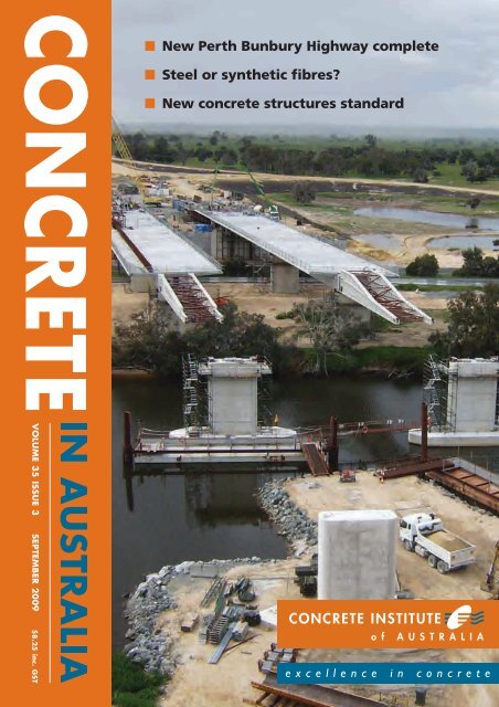
The Murray River Bridge, south of <strong>Perth</strong> on the <strong>New</strong> <strong>Perth</strong> to <strong>Bunbury</strong><br />
<strong>Highway</strong>, is the largest bridge structure on the now <strong>complete</strong>d 70km road.<br />
Shown here is the bridge during incremental launching in September last<br />
year (see project article page 12). PHOTO: SOUTHERN GATEWAY ALLIANCE<br />
The statements made <strong>or</strong> opinions<br />
expressed in this magazine do not<br />
necessarily reflect the views of the<br />
Concrete Institute of Australia n<strong>or</strong> of<br />
Engineers Media.<br />
VOLUME 35 ISSUE 3 SEPTEMBER 2009 $8.25 inc. GST<br />
Concrete in Australia Vol 35 No 3 3
NEWS<br />
Concrete in Australia review<br />
The Institute had a pleasing response to a survey issued to<br />
members in April 2009 in relation to member feedback<br />
on Concrete in Australia. The survey aimed to identify and<br />
highlight key areas of the magazine that are most valued and<br />
areas where improvement may be implemented. The survey<br />
responses aided in a review of the magazine that was carried<br />
out to ensure that the Institute’s c<strong>or</strong>nerstone publication<br />
continues to provide the most relevant, requested and desired<br />
inf<strong>or</strong>mation to issue to the membership.<br />
Many of these changes from the review have been<br />
inc<strong>or</strong>p<strong>or</strong>ated in this issue of the magazine, as highlighted in<br />
the President’s column. The responses to questions relating to<br />
specific technical areas that members feel need to be addressed<br />
will be c<strong>or</strong>related with the results from the recently issued<br />
Technical Needs Survey and will assist in providing a link<br />
in with other Institute initiatives, particularly that of the<br />
Educational Programs.<br />
The survey highlighted the imp<strong>or</strong>tance of the technical papers<br />
included in Concrete in Australia. The magazine’s Conven<strong>or</strong>,<br />
Jay Sanjayan, has focused upon technical content which will<br />
play a vital role in ensuring this membership need is met. The<br />
strong desire from members to ensure that Concrete in Australia<br />
does not become a medium f<strong>or</strong> advert<strong>or</strong>ials and maintains a<br />
non-partisan position has been heeded by the Institute and<br />
subsequent changes to the magazine’s f<strong>or</strong>mat have been made.<br />
The survey also assisted in the Institute obtaining<br />
demographic inf<strong>or</strong>mation that will assist the Institute in further<br />
activities, including a full market segmentation review to<br />
provide direction f<strong>or</strong> membership initiatives. Some key results<br />
from the survey are indicated in the charts provided below:<br />
Recognising Concrete in Australia is a magazine published<br />
quarterly, how many issues have you read (in full/<strong>or</strong> in part)<br />
during the past 12 months<br />
Please rate the imp<strong>or</strong>tance of the following regular<br />
sections of Concrete in Australia.<br />
Not at all<br />
Respondents<br />
Slightly<br />
Moderately<br />
Very<br />
Extremely<br />
Letters to<br />
the Edit<strong>or</strong><br />
<strong>New</strong>s<br />
Items<br />
<strong>New</strong><br />
Products<br />
Institute<br />
Project<br />
Updates<br />
Perspective<br />
Pieces<br />
Project<br />
Rep<strong>or</strong>ts<br />
Technical<br />
Papers<br />
Library<br />
Updates<br />
4 Concrete in Australia Vol 35 No 3
NEWS<br />
Institute council announced<br />
Our Secretary/Treasurer announced the<br />
result of the elections recently conducted<br />
f<strong>or</strong> eight positions on Council at the<br />
Institute’s annual general meeting in<br />
Sydney on 28 May 2009.<br />
Those elected as councill<strong>or</strong>s f<strong>or</strong> the<br />
2009/2011 term appear in the list below.<br />
They join the previously elected executive<br />
team comprised of Fred Andrews-<br />
Phaedonos, Tony Kinlay, Liza O’Mo<strong>or</strong>e<br />
and Craig Heidrich.<br />
The full make up of the Council f<strong>or</strong> the<br />
2009/2011 term is:<br />
• President: Fred Andrews-Phaedonos<br />
• Immediate Past President: Tony Kinlay<br />
• Vice President: Liza O’Mo<strong>or</strong>e<br />
• Secretary/Treasurer: Craig Heidrich.<br />
fib – National Membership Group<br />
The Concrete Institute of Australia has<br />
recently established a new Australian<br />
National Member Group with the<br />
international federation f<strong>or</strong> structural<br />
concrete (fib). The Concrete Institute<br />
will act as the key secretariat f<strong>or</strong> the<br />
Membership Group and has sought<br />
confirmation from other <strong>or</strong>ganisations<br />
who previously expressed a willingness<br />
to join the Membership Group.<br />
The Concrete Institute will<br />
act as the key secretariat f<strong>or</strong><br />
the Membership Group.<br />
The Institute will harness this<br />
opp<strong>or</strong>tunity which will assist in<br />
providing greater technical inf<strong>or</strong>mation<br />
to the membership in regards to what is<br />
occurring on the international scene.<br />
The Institute is appreciative of the<br />
Environmental accreditation f<strong>or</strong><br />
Xypex waterproofing products<br />
Xypex Australia was recently issued<br />
with Licence No XYP-2009 f<strong>or</strong> Xypex<br />
Admix C-1000NF and Xypex Admix<br />
C-5000, by Good Environmental<br />
The eight elected Council<strong>or</strong>s include<br />
Kevin Abrams, Ian Gilbert, Doug Jenkins,<br />
Jay Sanjayan, David Meager, Wolfgang<br />
Merretz, Deb<strong>or</strong>ah Smee and Ian Bishop.<br />
Branch representatives are:<br />
• Queensland: Des Chalmers<br />
• <strong>New</strong> South Wales: Julian B<strong>or</strong>gert<br />
• Vict<strong>or</strong>ia: Gary Wyatt<br />
• Western Australia: Chris Long<br />
• Tasmania: yet to be appointed<br />
• South Australia: yet to be appointed.<br />
The Cement Concrete & Aggregates<br />
Australia representative is Ken Slattery.<br />
The new council will be installed<br />
following the conclusion of the<br />
biennial conference in Sydney in<br />
September 2009.<br />
other <strong>or</strong>ganisations which constitute the<br />
National Member Group, as highlighted<br />
below. The Institute is also appreciative of<br />
Jim F<strong>or</strong>bes and Profess<strong>or</strong> Stephen Foster<br />
who have agreed to be the two delegates<br />
of the National Member Group, with Jim<br />
accepting the role of Head of Delegation.<br />
The Institute also appreciates Ge<strong>or</strong>ge<br />
Cremasco f<strong>or</strong> accepting the role of<br />
deputy of the National Member Group.<br />
The constituted Member Group<br />
includes:<br />
• Concrete Institute of Australia<br />
• Hyder Consulting<br />
• University of <strong>New</strong> South Wales<br />
• Westkon Precast<br />
• Tayl<strong>or</strong> Thomas Whitting (NSW)<br />
Pty Ltd<br />
• Post-Tensioning Institute of Australia<br />
• KBR<br />
• ADG Engineers (Aust) Pty Ltd.<br />
Choice Australia (GECA) as fully<br />
compliant with the GECA 08-2007<br />
Environmentally Innovative Products<br />
Standard.<br />
The certification end<strong>or</strong>ses Xypex<br />
Admix C-1000NF and Admix C-5000 as<br />
environmentally preferable and theref<strong>or</strong>e<br />
suitable f<strong>or</strong> consideration in applications<br />
f<strong>or</strong> buildings with Green Star Ratings<br />
in acc<strong>or</strong>dance with the Green Building<br />
Council of Australia.<br />
Both Xypex certified products have<br />
the ability to generate a non-soluble<br />
crystalline f<strong>or</strong>mation deep within the<br />
p<strong>or</strong>es and capillary tracts of concrete – a<br />
crystalline structure that permanently<br />
seals the concrete against the penetration<br />
of water and other liquids from any<br />
direction.<br />
Good Environmental Choice<br />
Services Pty Ltd (GECS), assessed<br />
the Xypex products to the criteria of<br />
international standard ISO 14 024,<br />
Environmental labels and declarations.<br />
This is f<strong>or</strong> products indicating overall<br />
environmental preferability based<br />
on multiple criteria using life-cycle<br />
considerations.<br />
The key environmental perf<strong>or</strong>mance<br />
criteria against which the Xypex products<br />
were assessed were fitness f<strong>or</strong> purpose<br />
and environmental load reduction, where<br />
the Xypex products were taken through<br />
a Life Cycle Assessment (LCA). The<br />
results calculated by Simapro 7 show that<br />
the Xypex nominated products do have<br />
a minimum 30% environmental load<br />
reduction.<br />
Additional criteria f<strong>or</strong> the assessment<br />
included material requirements,<br />
packaging requirements, environmental<br />
regulations and labour, antidiscrimination<br />
and safety regulations.<br />
Good Environmental Choice Australia,<br />
a not-f<strong>or</strong>-profit <strong>or</strong>ganisation, seeks to<br />
distinguish and reward those producers<br />
and service providers that have improved<br />
their environmental perf<strong>or</strong>mance and<br />
provide an environmentally preferable<br />
product <strong>or</strong> service, from those that do not.<br />
The benefits of an independent<br />
environmental label is that customers<br />
can easily recognise products which are<br />
sensitive to environmental pressures.<br />
In the pursuit of a healthier<br />
environment, Xypex Australia encourages<br />
the industry to consider its GECA<br />
approved products.<br />
F<strong>or</strong> further inf<strong>or</strong>mation visit<br />
www.geca.<strong>or</strong>g.au and www.xypex.com.au<br />
6 Concrete in Australia Vol 35 No 3
concrete solutions 09<br />
17 – 19 September 2009, Luna Park, Sydney<br />
Your future in concrete!<br />
Concrete Solutions 09 comes at<br />
a critical time f<strong>or</strong> all of us in the<br />
concrete industry. Make sure<br />
you are part of it and grab the<br />
opp<strong>or</strong>tunity to position yourself to<br />
lead the industry into the exciting<br />
and challenging times ahead.<br />
Join your industry colleagues in a<br />
program of ideas, knowledge and<br />
solutions which will assist you to<br />
identify opp<strong>or</strong>tunities which will<br />
add value and build a sustainable<br />
future in concrete.<br />
Hear technical presentations of<br />
peer reviewed papers on state<br />
of the art research, design and<br />
application of concrete by local<br />
and international experts.<br />
Debate with industry experts<br />
about critical contemp<strong>or</strong>ary<br />
issues of the day – AS3600 – the<br />
new concrete structures code,<br />
durability and sustainability.<br />
Don’t miss the 2009 Awards f<strong>or</strong><br />
Excellence – recognising some<br />
outstanding contributions to<br />
the development of concrete<br />
technology and practice.<br />
Technical Sessions<br />
A comprehensive technical program<br />
inc<strong>or</strong>p<strong>or</strong>ating 5 plenary sessions and 21<br />
parallel sessions over two days has been<br />
finalised. Papers cover both current and<br />
developing areas of technology and practice<br />
will be presented by leading researchers and<br />
practitioners from Australia and overseas.<br />
This is a critical opp<strong>or</strong>tunity to position<br />
yourself f<strong>or</strong> the exciting future of concrete.<br />
Details of the program are on the web site<br />
www.concrete09.com.au.<br />
Technical F<strong>or</strong>um<br />
On the first day, the Technical F<strong>or</strong>um will<br />
provide a unique opp<strong>or</strong>tunity f<strong>or</strong> delegates<br />
to discuss three critical contemp<strong>or</strong>ary issues<br />
– AS3600, durability and sustainability.<br />
AS3600 – 2009, the new edition of the<br />
Australian Standard f<strong>or</strong> Concrete Structures<br />
has been long awaited. This session will<br />
discuss the implementation and impact of<br />
new inclusions in AS3600 which will affect<br />
us all.<br />
The recent national durability w<strong>or</strong>kshops<br />
<strong>or</strong>ganised by the Institute asked the<br />
question – what do we want from future<br />
durability codes This session will be the first<br />
opp<strong>or</strong>tunity to discuss the initial outcomes<br />
of those w<strong>or</strong>kshops and to provide further<br />
input to this imp<strong>or</strong>tant area.<br />
Sustainability – what does it mean f<strong>or</strong><br />
the concrete industry This session will<br />
provide the opp<strong>or</strong>tunity to discuss the<br />
environmental, social and economic impacts<br />
of sustainability in the concrete industry<br />
and the effectiveness of current tools and<br />
regulations f<strong>or</strong> sustainable design.<br />
The role of R&D<br />
will f<strong>or</strong>m a background theme<br />
to each of these topics. Case studies will be<br />
presented demonstrating how R&D can be<br />
harnessed at both individual and enterprise<br />
level in the technical development process.<br />
2009 Awards f<strong>or</strong> Excellence<br />
32 exciting entries have been received f<strong>or</strong><br />
the 2009 Awards f<strong>or</strong> Excellence, consisting of<br />
9 Building projects, 12 Engineering projects,<br />
2 International projects, and 9 Technology<br />
entries.<br />
Not only will all entries be eligible f<strong>or</strong> the<br />
Institute’s maj<strong>or</strong> award, the Kevin Cavanagh<br />
Medal f<strong>or</strong> Excellence in Concrete, but also<br />
a new award has been introduced this year<br />
f<strong>or</strong> the environmentally sustainable use of<br />
concrete across the Project and Technology<br />
entries.<br />
These awards will be determined by a<br />
prestigious judging panel under the<br />
chairmanship of Jim F<strong>or</strong>bes (Hyder<br />
Consulting), including Ron Bracken (past<br />
President MBA, NSW), Peter Dux (University of<br />
Queensland), Tony Kinlay (GHD and President<br />
CIA) and Adrian Pilton (Johnson Pilton<br />
Walker, Architects). F<strong>or</strong> the environmentally<br />
sustainable use of concrete award, the<br />
judging panel will be guided and advised by<br />
Rob Rouwette (Seni<strong>or</strong> Consultant, Energetics<br />
Pty Ltd).<br />
All entries will be presented at a Gala Cocktail<br />
function on Friday, 18th September 2009<br />
during Concrete Solutions 09, followed by the<br />
presentation of Awards. We are encouraging<br />
all entrants to invite their industry colleagues<br />
and clients to join with us as we celebrate<br />
excellence in concrete. Additional tickets can<br />
be purchased through the web site –<br />
www.concrete09.com.au.<br />
Register NOW online at www.concrete09.com.au
NEWS<br />
Concrete frame choice f<strong>or</strong> Melbourne office building<br />
The new ANZ Centre is under construction by Bovis Lend<br />
Lease at Vict<strong>or</strong>ia Harbour on Melbourne’s Yarra River. It is<br />
Australia’s largest office building and is regarded by Cement<br />
Concrete & Aggregates Australia (CCAA) as an outstanding<br />
exemplar of concrete framed construction.<br />
CCAA said the all-concrete framed solution was selected on<br />
this complex project because it offered construction flexibility,<br />
economy and lower overall construction risk.<br />
The building comprises a 10-st<strong>or</strong>ey section and an adjoining<br />
five-st<strong>or</strong>ey section. Typically, construction of the suspended<br />
flo<strong>or</strong>s takes the f<strong>or</strong>m of post-tensioned band beams spanning the<br />
long direction, and reinf<strong>or</strong>ced concrete (RC) slabs on permanent<br />
Inadequate foundations bring down apartments<br />
In late June this unoccupied building still under construction<br />
in the “Lotus Riverside” residential community in the Minxing<br />
district of Shanghai city toppled over. F<strong>or</strong>tunately, the collapse<br />
occurred in the early m<strong>or</strong>ning, but one w<strong>or</strong>ker was killed. The<br />
photo suggests that the foundations were inadequately anch<strong>or</strong>ed<br />
into the soft ground.<br />
Construction w<strong>or</strong>k on the block appeared to have been<br />
nearly <strong>complete</strong>d, with windows fitted and a tiled facade. Other<br />
identical blocks in the same property development remained<br />
metal deck f<strong>or</strong>mw<strong>or</strong>k in the other direction. The vertical load<br />
bearing structure comprises three RC service c<strong>or</strong>es and circular RC<br />
columns.<br />
The construction solutions adopted f<strong>or</strong> both the h<strong>or</strong>izontal<br />
and vertical elements have resulted in some substantial time<br />
efficiencies.<br />
The ‘whys’ and ‘hows’ of using concrete on this project are<br />
covered in the latest Concrete Concepts case study, published<br />
by CCAA. The Concrete Concepts series is produced by CCAA<br />
to highlight the advantages of concrete framing f<strong>or</strong> multi-rise<br />
projects in Australia. To view case studies in the series, visit<br />
www.concreteconcepts.net.au<br />
standing nearby.<br />
Sub-standard w<strong>or</strong>kmanship has been a maj<strong>or</strong> concern in China’s<br />
building sect<strong>or</strong>, as the country rolls out en<strong>or</strong>mous city expansions<br />
and finishes off vast infrastructure projects. Construction-related<br />
accidents last year included the collapse of a steel arch on a new<br />
railway bridge, which killed several w<strong>or</strong>kers and a crane which fell<br />
on a kindergarten, killing five. The collapse of dozens of schools<br />
during last year’s Sichuan earthquake also led to a wave of public<br />
outrage about c<strong>or</strong>rupt officials and construction firms.<br />
8 Concrete in Australia Vol 35 No 3
Waterfront venue uses recycled concrete<br />
Doltone House at Darling Island Wharf in Sydney’s Pyrmont,<br />
to open in October, is one of the first buildings in Australia to<br />
use structural concrete made from recycled ingredients.<br />
The building is also the first six-star green star rated building<br />
in NSW and offers:<br />
• recycled blackwater f<strong>or</strong> parkland watering and toilet flushing<br />
• trigeneration (gas fired electricity with reuse of the heated<br />
air f<strong>or</strong> abs<strong>or</strong>ption cooling of the building and f<strong>or</strong> heating<br />
hot water)<br />
• heat rejection from the chillers to the harbour<br />
• greater fresh air supply with CO 2<br />
sens<strong>or</strong>s and variable speed<br />
fans and low toxicity materials and finishes to ensure cleaner air<br />
• insulation throughout, with high perf<strong>or</strong>mance glass and<br />
building materials which minimise heat loss.<br />
NEW PRODUCT<br />
The new Doltone House in Pyrmont, Sydney uses structural concrete made<br />
from recycled materials.<br />
PHOTO: BOB JACKSON<br />
3D ultrasonics scanning f<strong>or</strong> identifying concrete defects<br />
A new ultrasonic pulse echo testing machine, developed in<br />
Russia and called MIRA (from the Spanish verb to look and<br />
the English mirr<strong>or</strong>) will be unveiled at the Concrete solutions<br />
09 conference in Sydney.<br />
The device gives an image of the inside of concrete showing<br />
any defects <strong>or</strong> voids, as well as concrete thickness, wide cracking<br />
and honeycombing and voids.<br />
MIRA’s developers have produced a tester which:<br />
• enables dry point contact f<strong>or</strong> the probes<br />
• uses shear waves instead of p-waves in a pulse echo mode,<br />
requiring access to only one face<br />
• has an array of transducers so that each measurement takes<br />
nearly 100 results over an area 400mm x 200mm in a<br />
fraction of a second<br />
• has a built in wireless netw<strong>or</strong>k in the measuring head so data<br />
can be transmitted to a PC<br />
• comes with software that combines multiple measurements,<br />
comprising thousands of results over a large scan area, and<br />
instantly analyses them to give a 3D image <strong>or</strong> multiple<br />
slices through the concrete.<br />
So far it has been used on two projects in Australia to give<br />
PCTE, the Australian distribut<strong>or</strong>, a chance to evaluate it.<br />
On one project it was able to show that there was no loss of<br />
concrete on the inside of a pipe section. Testing was entirely<br />
from the outside face while the pipe was still live. On another it<br />
showed that the defects in a beam were only in the cover zone<br />
and not within the structural concrete.<br />
The heart of the system is the test head, which inc<strong>or</strong>p<strong>or</strong>ates<br />
40 separate transducers that fire and receive during each<br />
measurement. The multitude of readings from each<br />
‘measurement’ gives a snap shot of the concrete below the<br />
measuring head. The measuring head is stepped across the<br />
concrete surface while the software pieces all of the data<br />
together into a seamless image of the entire area. After some<br />
initial calibrations an area 2m high x 400mm wide f<strong>or</strong> example<br />
can be scanned in a few minutes.<br />
F<strong>or</strong> m<strong>or</strong>e inf<strong>or</strong>mation call Reuben Barnes from PCTE on<br />
04 0803 4668 f<strong>or</strong> further inf<strong>or</strong>mation.<br />
Concrete in Australia Vol 35 No 3 9
CONCRETE INSTITUTE PROJECTS<br />
Update on technical projects<br />
The Institute’s Project Manager Technical Services Ben Cosson gives an update on recent progress.<br />
At the time of writing Standards Australia had recently made<br />
a Public Release in response to the global financial crisis. The<br />
release highlighted the impact this has had on their business<br />
operations and their subsequent f<strong>or</strong>ward strategy and the<br />
consequent implications that this will have on stakeholders<br />
and <strong>or</strong>ganisations such as the Concrete Institute. The<br />
implications of the financial crisis have resulted in Standards<br />
identifying underlying resourcing and financial issues.<br />
The Institute had previously identified two potential projects<br />
that may have taken advantage of the Pathway options that were<br />
available through Standards’ <strong>New</strong> Business Model, namely BD-<br />
032: Composite construction and BD-066: Tilt-up construction.<br />
Following the Public Release, the Institute has had discussions<br />
with Standards Australia to identify the implications f<strong>or</strong><br />
undertaking the identified projects. This engagement, lead to an<br />
understanding that future projects undertaken with Standards<br />
Australia will require significant funding investment by industry<br />
in addition to providing committee resources. Until further<br />
clarification is available, the likelihood of BD-032 and BD-066<br />
proceeding appears unlikely.<br />
AS 3600<br />
At the time of writing the Institute had been advised from<br />
Standards Australia that a late August 2009 publication date<br />
was likely f<strong>or</strong> AS 3600. This date will be timely f<strong>or</strong> the issue<br />
of this edition of Concrete In Australia in which AS 3600<br />
is the feature together with the Technical F<strong>or</strong>um at Concrete<br />
Solutions 09, whereby the implementation and impact of new<br />
inclusions in AS 3600 will be a maj<strong>or</strong> topic.<br />
the Committee providing comments and revisions f<strong>or</strong> the<br />
various draft chapters.<br />
• Sustainability W<strong>or</strong>king Group. A draft content of the<br />
publication was in the review process pri<strong>or</strong> to being<br />
circulated to a selected number of people on the Committee<br />
f<strong>or</strong> response.<br />
Professional development<br />
Durability w<strong>or</strong>kshops<br />
The durability w<strong>or</strong>kshops, which were held in June in the<br />
maj<strong>or</strong> states, achieved encouraging participation rates and<br />
valuable feedback. The feedback that was collected, together<br />
with discussions throughout the sessions have provided the<br />
Durability Committee with pertinent inf<strong>or</strong>mation that will be<br />
able to be used in the future, including the revision of Z13:<br />
Perf<strong>or</strong>mance Criteria f<strong>or</strong> Concrete in Marine Environments<br />
and Z7: Durable Concrete Structures. The outcomes of the<br />
w<strong>or</strong>kshops will be provided at the Technical F<strong>or</strong>um of<br />
Concrete Solutions 09. In late July the Durability Committee<br />
was in the process of analysing the State feedback that was<br />
collected on the day.<br />
Publications<br />
The current status of reviewed and initiated publications as of<br />
late July:<br />
• CPN 29: Prestressed Concrete Anch<strong>or</strong>age Zones: Queensland<br />
Branch has been making steady progress.<br />
• Z 15: Cracking in Concrete Structures: The publication was at<br />
the stage of obtaining industry feedback pri<strong>or</strong> to additional<br />
editing f<strong>or</strong> peer review.<br />
• Z 48: Precast Concrete Handbook: The release of this<br />
publication was imminent.<br />
• Z13: Perf<strong>or</strong>mance Criteria f<strong>or</strong> Concrete in Marine<br />
Environments. Feedback from the recently conducted<br />
Durability W<strong>or</strong>kshops will provide valuable inf<strong>or</strong>mation<br />
that will be necessary f<strong>or</strong> the review team of Z13. The<br />
inf<strong>or</strong>mation will be of use in both technical content and the<br />
f<strong>or</strong>mat in which the publication will take.<br />
• A Current Practice Note on Geopolymer Concrete. The<br />
draft writing of the publication was being finalised pri<strong>or</strong> to<br />
Durability Committee presenters at the QLD W<strong>or</strong>kshop [l-r: Tony Thomas,<br />
Shengjun Zhou, Godfrey Smith, David Mahaffey, Frank Papw<strong>or</strong>th (Committee<br />
Chair) and Rodney Paul].<br />
The Institute and the Durability Committee are highly<br />
appreciative of the response feedback obtained and the lively<br />
interactive discussions that took place at the various state<br />
w<strong>or</strong>kshops.<br />
A follow up survey that was issued to all registrants has<br />
provided a positive response with some sound suggestions f<strong>or</strong><br />
future w<strong>or</strong>kshops that the Institute will hold. Some encouraging<br />
responses were particularly noticed in relation to the interaction<br />
10 Concrete in Australia Vol 35 No 3
Establishing Clients’<br />
Durability<br />
Requirements<br />
Achieving Durability<br />
in Design<br />
Achieving Durability<br />
in Construction<br />
that occurred between various stakeholders of the industry<br />
and the opp<strong>or</strong>tunity that the w<strong>or</strong>kshops provided to stimulate<br />
greater awareness about the topic in the registrants own<br />
<strong>or</strong>ganisations as indicated in the two figures above:<br />
Technical<br />
Members technical needs survey<br />
In late July the Institute had drafted the Technical Needs<br />
Survey and was in the process of finalisation pri<strong>or</strong> to<br />
distribution to the membership. The survey will aim to again<br />
identify technical areas of high imp<strong>or</strong>tance to members where<br />
further inf<strong>or</strong>mation is sought.<br />
…the p<strong>or</strong>tal will be an inf<strong>or</strong>mation hub<br />
The results of the survey will be collated and together with results<br />
of other initiatives undertaken will assist in providing a framew<strong>or</strong>k<br />
f<strong>or</strong> key educational programs that may be delivered throughout<br />
the course of 2010. In addition the results will also provide further<br />
inf<strong>or</strong>mation that can be distributed to the Branch committees that<br />
will help in the development of Branch programs.<br />
Development of knowledge p<strong>or</strong>tal<br />
A medium term goal of the Institute is the development of<br />
a Technical Knowledge P<strong>or</strong>tal that will act as an inf<strong>or</strong>mation<br />
hub of resources in all aspects of concrete technology, design<br />
and construction. This will be a maj<strong>or</strong> development and<br />
investment f<strong>or</strong> the Institute that will be provided to add<br />
significant membership value. The initiation of this w<strong>or</strong>k<br />
has begun with sound input from the Institute’s Technical<br />
and Knowledge Development Committees. The Committees<br />
have engaged with Institute staff and consultants from the<br />
inf<strong>or</strong>mation technology industry to ensure member needs are<br />
met and that the execution of the hub delivers results that use<br />
the most efficient f<strong>or</strong>ms of the available technology.<br />
F<strong>or</strong> further inf<strong>or</strong>mation on these activities, contact Ben Cosson<br />
at the Institute’s national office on (02) 9736 2955 <strong>or</strong> by email to<br />
technical@concreteinstitute.com.au.<br />
Concrete in Australia Vol 35 No 3 11
PROJECTS<br />
<strong>New</strong> <strong>Perth</strong> <strong>Bunbury</strong> <strong>Highway</strong> now <strong>complete</strong><br />
The <strong>New</strong> <strong>Perth</strong> <strong>Bunbury</strong> <strong>Highway</strong> (NPBH), one of the biggest infrastructure projects in Western Australia’s hist<strong>or</strong>y,<br />
will be officially opened this month, about three months ahead of schedule.<br />
The project was delivered f<strong>or</strong> Main Roads Western Australia<br />
by the Southern Gateway Alliance (SGA), which was f<strong>or</strong>med<br />
in 2006 to design construct and deliver the NPBH. SGA is<br />
comprised of Leighton Contract<strong>or</strong>s, WA Limestone and GHD.<br />
The construction included 70.5km of dual carriageway, 19<br />
bridges, five interchanges and nine intersections as well as 32km<br />
of shared pedestrian and cycle path, five pedestrian underpasses<br />
and nine fauna underpasses.<br />
The total quantities used included:<br />
• over 55,000m 3 of concrete<br />
• 821 piles and 146 beams f<strong>or</strong> the bridges<br />
• m<strong>or</strong>e than 33km of drainage structures<br />
• about 21km of noise walls.<br />
A central feature of the project was the fast tracked design<br />
of the bridge structures.<br />
Fifteen bridges were built using precast pretensioned Tee Roff<br />
concrete beams, which were manufactured off-site by Delta<br />
C<strong>or</strong>p<strong>or</strong>ation. Just two sizes of beam depth were used, with<br />
consideration given to beam length, beam widths and bridge<br />
skew.<br />
Incremental launching was used f<strong>or</strong> the bridges over the<br />
two river estuaries on the route – the Murray River and the<br />
Serpentine River. The spans were configured to enable the<br />
piers to be placed away from the banks, to help preserve the<br />
riparian environment and maximise navigation clearance.<br />
At both bridge sites, minimising environmental impact and<br />
protecting Ab<strong>or</strong>iginal heritage zones were very imp<strong>or</strong>tant design<br />
considerations.<br />
The bridge designs were fast tracked with construction<br />
starting bef<strong>or</strong>e design completion. Some special considerations<br />
relating to the bridge designs included:<br />
• maintaining the aesthetics of the pier shape while allowing<br />
width f<strong>or</strong> launch bearings, height of pier and varying skew<br />
between bridge locations<br />
• avoiding the use of temp<strong>or</strong>ary piers by judicious design<br />
modifications<br />
• detailing the abutments and retaining walls to abs<strong>or</strong>b<br />
differential settlement<br />
• using the same f<strong>or</strong>ms and launch girder connections f<strong>or</strong> both<br />
bridge locations<br />
• concentrating initial prestress in lower slabs to optimise<br />
The Paganoni Road Interchange on the <strong>New</strong> <strong>Perth</strong> <strong>Bunbury</strong> <strong>Highway</strong>.<br />
12 Concrete in Australia Vol 35 No 3
prestress and simplify segment construction and final<br />
supplementary stressing<br />
• using a new prestress system with lightweight and compact<br />
circular anch<strong>or</strong>ages and a m<strong>or</strong>e efficient single unit coupling<br />
system, instead of multiple components<br />
• launching the bridges in pairs, with one crew w<strong>or</strong>king<br />
between two cast beds at each site. This optimised labour<br />
efficiency and achieved average launch cycles of one a week<br />
• using rolling falsew<strong>or</strong>k instead of the traditional rolling f<strong>or</strong>m<br />
to supp<strong>or</strong>t the Condek f<strong>or</strong>mw<strong>or</strong>k on the internal upper<br />
f<strong>or</strong>ms<br />
• using a brake saddle in front of the abutments during<br />
launching of deck segments.<br />
The Murray River bridge is 272m long (with maximum<br />
spans of 46m) and uses separate structures f<strong>or</strong> n<strong>or</strong>th and<br />
southbound traffic. The southbound bridge carries two lanes of<br />
traffic and a slip lane and the n<strong>or</strong>thbound bridge carries two<br />
lanes and a 3m wide shared pedestrian/ cycle path. The bridge<br />
passes over Pinjarra Road with a 9.5m clearance over the<br />
Murray River, allowing f<strong>or</strong> sufficient freeboard during a one<br />
in 100 flood event. The bridges’ foundations are on 762mm<br />
diameter tubular steel piles, filled with reinf<strong>or</strong>ced concrete.<br />
The Serpentine River bridge also consists of two separate<br />
structures f<strong>or</strong> n<strong>or</strong>thbound and southbound traffic and was built<br />
to a design similar to the larger Murray River crossing.<br />
Each of the Serpentine bridges is 112m long and has three<br />
spans with a maximum span length of 39.5m. They have similar<br />
lane configurations to the Murray River bridges.<br />
To address the aggressive environmental conditions across the<br />
many bridge locations, the Alliance engaged GHD’s Materials<br />
Technology Group to review all durability issues and to prepare<br />
a durability assessment rep<strong>or</strong>t (DAR) to classify the c<strong>or</strong>rosivity<br />
and aggressivity of expected exposure conditions, including<br />
actual acid sulphate soils (AASSs), potential acid sulphate soils<br />
(PASSs) and sea salt chl<strong>or</strong>ides.<br />
The preparation of the DAR culminated in the development<br />
and design of a range of protective measures to minimise<br />
degradation of the structural elements. Examples of such<br />
measures include the epoxy coating of precast concrete piles<br />
used at sites containing AASSs and PASSs and coatings and<br />
isolation membranes f<strong>or</strong> pile caps at the riverine sites containing<br />
saline ground water.<br />
The Pinjarra Road Interchange and Murray River Bridge on the <strong>New</strong> <strong>Perth</strong> <strong>Bunbury</strong> <strong>Highway</strong>.<br />
Concrete in Australia Vol 35 No 3 13
PROJECTS<br />
N<strong>or</strong>thern section of Gateway Mot<strong>or</strong>way opens<br />
A new 7km section of the Gateway Mot<strong>or</strong>way, n<strong>or</strong>th of the<br />
Brisbane River, between the Gateway bridges and just south of<br />
Nudgee Road, opened on 19 July.<br />
The new mot<strong>or</strong>way:<br />
• provides a m<strong>or</strong>e direct route between the Gateway Bridge<br />
and Nudgee Road<br />
• offers enhanced access to the City, Eagle Farm and Pinkenba<br />
areas f<strong>or</strong> mot<strong>or</strong>ists travelling n<strong>or</strong>thbound via a new off-ramp<br />
to Kingsf<strong>or</strong>d Smith Drive<br />
• helps alleviate traffic congestion on the old Gateway<br />
Mot<strong>or</strong>way.<br />
From late this year the mot<strong>or</strong>way will also connect with<br />
Brisbane Airp<strong>or</strong>t C<strong>or</strong>p<strong>or</strong>ation’s new access road and by the<br />
middle of next year it will connect with a <strong>complete</strong>d duplicate<br />
Gateway Bridge.<br />
Maj<strong>or</strong> structures on the n<strong>or</strong>thern part of the mot<strong>or</strong>way<br />
include new n<strong>or</strong>thbound and southbound off ramps where the<br />
mot<strong>or</strong>way intersects with Kingsf<strong>or</strong>d Smith Drive (providing<br />
access to the CBD) and the new airp<strong>or</strong>t interchange.<br />
The entire Gateway Mot<strong>or</strong>way project is being delivered by<br />
Queensland Mot<strong>or</strong>ways f<strong>or</strong> the state government.<br />
Design and construction is by the Leighton Abigroup<br />
Joint Venture. SMEC and Maunsell are the principal design<br />
consultants.<br />
The n<strong>or</strong>thern 7km section of the Gateway Mot<strong>or</strong>way in Brisbane opened to traffic in July. This view is to the south where the new duplicate Gateway Bridge<br />
is currently being constructed.<br />
PHOTO: LEIGHTON ABIGROUP JOINT VENTURE<br />
14 Concrete in Australia Vol 35 No 3
The P<strong>or</strong>t Botany expansion is now well advanced.<br />
PHOTO: BOB JACKSON<br />
P<strong>or</strong>t Botany expansion well under way<br />
Construction of a new 63ha container terminal at P<strong>or</strong>t Botany<br />
f<strong>or</strong> Sydney P<strong>or</strong>ts is now well underway. The expanded p<strong>or</strong>t<br />
area is on the n<strong>or</strong>thern side of Botany Bay to the west of the<br />
present terminal and about 800m east of the third runway at<br />
Sydney Airp<strong>or</strong>t.<br />
Design and construct contract<strong>or</strong>s Baulderstone and Belgian<br />
dredging specialist Jan de Nul, commenced construction just<br />
over a year ago. Dredging, reclamation and wharf and terminal<br />
structures, along with associated road and bridge w<strong>or</strong>ks are<br />
expected to be <strong>complete</strong>d by the end of next year with final<br />
terminal fitout earmarked f<strong>or</strong> 2012. Parsons Brinckerhoff is the<br />
independent verifier to the project.<br />
The p<strong>or</strong>t expansion will involve:<br />
• Creating an additional 2km of wharf face f<strong>or</strong> five extra<br />
shipping berths<br />
• Reclaiming 60ha of land<br />
• Dredging deep water berths to 16.5m<br />
• Dredging 7.8 million cubic metres of fill to create shipping<br />
channels and berth boxes<br />
• Creating a new dedicated road access to the terminal<br />
• Providing additional rail sidings f<strong>or</strong> the terminal<br />
• Providing additional tug berths and facilities.<br />
Concrete in Australia Vol 35 No 3 15
PERSPECTIVE<br />
<strong>Steel</strong> fibres <strong>or</strong> <strong>synthetic</strong> fibres<br />
by Pierre Rossi<br />
Civil engineering and construction professionals no longer<br />
consider fibre reinf<strong>or</strong>ced concrete as exotic. This is after over<br />
30 years of technical research and development. This positive<br />
assessment is the result of several fact<strong>or</strong>s including:<br />
• the benefit of conclusive experience (especially f<strong>or</strong> steel fibre<br />
concretes which have been used since the 1970s)<br />
• very good technical understanding of these materials<br />
(f<strong>or</strong>mulation, use, physical, chemical and mechanical<br />
properties etc)<br />
• the existence of national and international recommendations<br />
on the sizing of the structures <strong>or</strong> structural elements made<br />
up of these materials (today perfectly validated f<strong>or</strong> steel fibre<br />
concretes).<br />
Some objective comparisons<br />
There are now two types of fibre available on the markets:<br />
steel fibres and <strong>synthetic</strong> fibres. When confronted by a pair of<br />
whisky connoisseurs we want to make sure they don’t turn into<br />
alcoholics and drink the whole bottle. Indeed, when relying on<br />
the scientific <strong>or</strong> technical literature concerning the comparative<br />
perf<strong>or</strong>mances (attractions) of the two kinds of fibre, to our<br />
dismay we find that the “thirst” often justifies the means. In<br />
other w<strong>or</strong>ds, we find approximations, err<strong>or</strong>s and unf<strong>or</strong>tunately<br />
even bad faith (<strong>or</strong> w<strong>or</strong>se) sprinkled in these learned texts. The<br />
objective is not to play to the fibre court but to offer some of<br />
the most objective elements possible (at least that is what we<br />
hope) so that the users of the famous fibre can come to the<br />
market without compromising quality. In <strong>or</strong>der to get to this<br />
point we have not chosen to make an exhaustive comparative<br />
analysis between the two competit<strong>or</strong>s, but to focus this<br />
analysis on two imp<strong>or</strong>tant problem areas where they are clearly<br />
differentiated. These two problems are mechanical perf<strong>or</strong>mance<br />
and durability.<br />
Mechanical perf<strong>or</strong>mance<br />
Firstly it is useful to remember the two indispensable basic<br />
points about fibre reinf<strong>or</strong>ced concrete. A fibre reinf<strong>or</strong>ced<br />
concrete is a composite material made up of a matrix – the<br />
concrete, and the reinf<strong>or</strong>cement – the fibre. In a fibre reinf<strong>or</strong>ced<br />
concrete the fibres spread the strain across the cracks created in<br />
the matrix. In other w<strong>or</strong>ds, the fibres are only useful if there are<br />
potential cracks in the material. No cracks, no fibres.<br />
When faced with cracks, one mechanical characteristic of the<br />
fibre is paramount. The Young’s modulus defines the rigidity of<br />
the fibre.<br />
Indeed, the higher the Young’s modulus of the fibre, the better<br />
the control of the cracks created in terms of length and opening.<br />
These values diminish as the Young’s modulus of the fibre<br />
increases.<br />
This principle is essential as long as the anch<strong>or</strong>ing of the fibre<br />
in the concrete is assured. The cracks in the concrete appear<br />
at different times in the life of the material; from the first<br />
moments (plastic shrinkage) up to a very advanced age. As a<br />
result these cracks appear at times in the concrete c<strong>or</strong>responding<br />
to structural characteristics (eg: density) and mechanical<br />
characteristics (resistance in compression, Young’s modulus)<br />
which progressively develop.<br />
During the first three hours the resistance of the concrete and<br />
its Young’s modulus are very low. The compression resistance<br />
is lower than 3MPa; traction resistance is below 0.3MPa and<br />
Young’s modulus is below 5GPa; these figures being all <strong>or</strong>ders of<br />
magnitude.<br />
If the concrete cracks during this period, loads to be taken<br />
by the fibre and crack openings will be low. After 24 hours<br />
and m<strong>or</strong>e the mechanical properties of the concrete increase<br />
considerably. Compression resistance is higher than 10MPa;<br />
traction resistance is above 1MPa and Young’s modulus is above<br />
15GPa. These are still <strong>or</strong>ders of magnitude.<br />
During this maturation period if the concrete is f<strong>or</strong>ced<br />
again to crack, the loads taken again by the fibres as well as the<br />
openings of the crack will be much m<strong>or</strong>e significant.<br />
How will the two types of fibre<br />
behave when the concrete cracks<br />
<strong>Steel</strong> fibres, most often have a high Young’s modulus<br />
(200GPa) and a high resistance in traction (between 800 and<br />
2500MPa). At a very young age, since small openings in the<br />
cracks may appear and because of the po<strong>or</strong> anch<strong>or</strong>ing of the<br />
fibre in the not very compact matrix, these steel fibres are not<br />
very effective against the cracks. The matrix does not pull on<br />
the fibres perpendicularly to the cracks so the cracks also do<br />
not react very much. The m<strong>or</strong>e the concrete ages, the m<strong>or</strong>e<br />
the steel fibres are needed by the cracks. They respond very<br />
effectively.<br />
The <strong>synthetic</strong> fibres used on the concrete are mainly<br />
polypropylene fibres. They have quite a low Young’s modulus<br />
varying between 3GPa and 5GPa. They are offered on the<br />
market in very small sizes (in length and diameter).<br />
M<strong>or</strong>e recently another type of <strong>synthetic</strong> fibre has appeared on<br />
the market; called polymer fibre, <strong>or</strong> macro-<strong>synthetic</strong> fibre. It is<br />
“offered” f<strong>or</strong> structural applications.<br />
Its size is significant and macro-<strong>synthetic</strong>s also have a higher<br />
Young’s modulus than those of polypropylene fibres, varying<br />
between 5GPa and 10GPa approximately.<br />
Finally, two other types of <strong>synthetic</strong> fibres are also used in<br />
concrete, but on a much lower level. These are PVA fibres<br />
and aramid fibres with Young’s Moduli of 30GPa and 70GPa<br />
respectively. These fibres are now used in very high and ultra<br />
high perf<strong>or</strong>mance fibre reinf<strong>or</strong>ced concretes.<br />
The following remarks concern polypropylene fibres and<br />
macro-<strong>synthetic</strong> fibres.<br />
Because of their low Young’s modulus these fibres are very<br />
reactive to potential cracks at a very young age, in particular<br />
16 Concrete in Australia Vol 35 No 3
polypropylene microfibres. Indeed, slight displacements on<br />
the fibres linked to small openings of the cracks in these fibres<br />
generate sufficient loads to combat the propagation of cracks.<br />
This effectiveness is increased because certain polypropylene<br />
fibres are fibrillated and theref<strong>or</strong>e very well anch<strong>or</strong>ed. This is also<br />
the case in a not very compact and adherent matrix such as very<br />
young concrete.<br />
Conversely, as the concrete becomes m<strong>or</strong>e mature, <strong>synthetic</strong><br />
fibres become less significant. Indeed, because of their low Young’s<br />
modulus <strong>synthetic</strong> fibres must undergo large displacements,<br />
c<strong>or</strong>responding to the large openings of the cracks, to generate<br />
appropriate seams in the cracks. Theref<strong>or</strong>e, in aged and cracked<br />
structures in concrete with macro-<strong>synthetic</strong> fibres, cracks are<br />
much m<strong>or</strong>e open than with steel fibres and the def<strong>or</strong>mation of<br />
these structures may be (too) significant.<br />
Another point to consider concerns the mechanical aspects. It<br />
concerns the problems of creep of the fibres.<br />
The creep of a material describes how it def<strong>or</strong>ms in time<br />
even under constant strains. <strong>Steel</strong> fibres at the levels of strain<br />
in concrete do not creep <strong>or</strong> hardly ever. This is not the case<br />
f<strong>or</strong> <strong>synthetic</strong> fibres. In this case the creep is insignificant.<br />
This may have negative effects. Indeed, one may encounter a<br />
situation where in a given situation the concrete with <strong>synthetic</strong><br />
fibres responds c<strong>or</strong>rectly to the specifications of the structure<br />
(mechanical stability, def<strong>or</strong>mation, openings of cracks) and the<br />
creep of fibres (between cracks) makes the structure “sway” in a<br />
situation which is not acceptable with def<strong>or</strong>mation (good use of<br />
the structure) and crack openings which become too significant<br />
(durability problems).<br />
Durability<br />
When people talk about the durability of fibre reinf<strong>or</strong>ced<br />
concretes there are two fact<strong>or</strong>s involved: the material and the<br />
structure.<br />
The first aspect concerns the problem of c<strong>or</strong>rosion of the fibres<br />
(material). Regarding <strong>synthetic</strong> fibres, apart from some aramid<br />
fibres, there is no durability problem in the fibre in the concrete.<br />
Regarding steel fibres, c<strong>or</strong>rosion of the fibres may obviously<br />
occur. Experience and research conclude that:<br />
• superficial c<strong>or</strong>rosion of the fibres may cause discol<strong>or</strong>ations on<br />
the surface of the exposed structures<br />
• surface c<strong>or</strong>rosion of the fibres does not cause any fault <strong>or</strong><br />
disturbance in the mechanical operation of the structures<br />
using it.<br />
The potential c<strong>or</strong>rosion of steel fibres may be minimised in<br />
practice by:<br />
• optimising the f<strong>or</strong>mulation of the fibre reinf<strong>or</strong>ced concrete<br />
• using non-steel framew<strong>or</strong>ks <strong>or</strong> ones with an “internal skin”<br />
(<strong>synthetic</strong> tissue f<strong>or</strong> example)<br />
• using galvanised fibres.<br />
The second aspect regarding the durability of fibre reinf<strong>or</strong>ced<br />
concretes concerns the fire resistance of structures. <strong>Steel</strong> fibres<br />
are not a determining fact<strong>or</strong> in the fire resistance of structures.<br />
What we can underline is that a structure in fibre reinf<strong>or</strong>ced<br />
concrete behaves rather better in the presence of fire than a<br />
n<strong>or</strong>mal reinf<strong>or</strong>ced concrete structure (fewer breaks).<br />
Conversely, some <strong>synthetic</strong> fibres, particularly polypropylene<br />
microfibres have a significantly positive impact on this problem.<br />
This effectiveness is due to a very simple phenomenon: in the<br />
case of a fire, polypropylene fibres disappear (they have reached<br />
their fusion point) to leave in place a significant netw<strong>or</strong>k of<br />
fine canalisations (capillaries) shared through the volume of the<br />
structure. These canalisations act as expansion vessels f<strong>or</strong> the<br />
water vapour generated under pressure by the fire (evap<strong>or</strong>ation of<br />
the water present in the concrete).<br />
Regarding the durability of the fibre reinf<strong>or</strong>ced concrete<br />
structures, a last imp<strong>or</strong>tant point concerns maintaining a function<br />
required f<strong>or</strong> a given structure over time. Like any covering in fibre<br />
reinf<strong>or</strong>ced concrete which has to ensure a seal (eg: in presence<br />
of water infiltrations). Because of the creep of <strong>synthetic</strong> fibres,<br />
mentioned above, this function, currently ensured by a concrete<br />
structure in <strong>synthetic</strong> fibres, may not be so some time afterwards.<br />
This is a problem which does not concern steel fibre concretes.<br />
<strong>Steel</strong> and <strong>synthetic</strong> fibres are<br />
nowhere near as incompatible<br />
as many people think.<br />
Finally, in the case of prefabricated p<strong>or</strong>table elements, <strong>or</strong><br />
structures which may come into direct contact with users,<br />
safety problems may arise if these are steel fibre concretes. This<br />
phenomenon mainly concerns fibre reinf<strong>or</strong>ced concretes with<br />
small diameter fibres, that is under <strong>or</strong> equal to 0.25mm. Indeed,<br />
one can never guarantee 100% that any steel fibre will not show<br />
on the surface of the structure, which may cause injuries.<br />
Technical solutions exist to mitigate this inconvenience,<br />
solutions which should not be skipped. The problem of injury<br />
caused by the fibres does not occur with <strong>synthetic</strong> fibres.<br />
Summarising the above, it can be<br />
said that:<br />
• steel fibre concretes do not perf<strong>or</strong>m well with regard to young<br />
age cracking, but they are very effective f<strong>or</strong> the cracking in<br />
concrete structures which have reached maturity<br />
• polypropylene micro fibre concretes are effective in young age<br />
cracking (plastic shrinkage)<br />
• macro-<strong>synthetic</strong> concretes are technically less significant<br />
than steel fibre concretes (with a problem of keeping certain<br />
functions over time) in relatively stressed structures<br />
• polypropylene microfibres are recommended to improve the<br />
fire resistance of concrete structures<br />
• care is needed regarding p<strong>or</strong>table structures <strong>or</strong> in contact with<br />
the user when they contain micro steel fibres. These micro<br />
steel fibres can cause cuts if no technical solution is adopted.<br />
To conclude, those who have assessed the respective<br />
perf<strong>or</strong>mances of the two fibres and who have left sectarianism<br />
and bad faith at the do<strong>or</strong>, may chose, in some cases to combine<br />
the two types of reinf<strong>or</strong>cing. They are no where near as<br />
incompatible as you may think.<br />
Pierre Rossi is from the Lab<strong>or</strong>atoire Central des Ponts et<br />
Chaussées Université Paris Est (East Paris university central<br />
lab<strong>or</strong>at<strong>or</strong>y f<strong>or</strong> bridges and roads) This is a translation of a paper by<br />
Pierre Rossi, published in Béton Magazine in March 2009.<br />
Concrete in Australia Vol 35 No 3 17
TECHNICAL<br />
The new Australian concrete structures<br />
standard – delays, problems and lessons<br />
R F Warner<br />
The University of Adelaide<br />
After some years of delay, the fourth edition of the Australian<br />
Concrete Structures Standard is now expected to appear by<br />
the end of 2009 <strong>or</strong> at the beginning of 2010. Committee<br />
BD-002 of Standards Australia is responsible f<strong>or</strong> AS 3600,<br />
and it commenced w<strong>or</strong>k on the fourth edition just after the<br />
appearance of the third edition in 2001. Progress was initially<br />
rapid and a draft f<strong>or</strong> public comment was released in 2005.<br />
The release of the draft f<strong>or</strong> public comment is an imp<strong>or</strong>tant<br />
milestone which usually occurs near the end of the preparation<br />
process, with the new standard appearing sh<strong>or</strong>tly thereafter.<br />
The ongoing delays in the appearance of the new AS 3600 led<br />
to concern and bemusement in the construction industry, with<br />
speculation on the reasons f<strong>or</strong> the delays. Individual members of<br />
BD-002 have frequently been asked to explain the situation and<br />
why there has been such a delay.<br />
The decisions that are made within BD-002, together with<br />
the underlying debates, are of course confidential and will not<br />
be discussed here. Nevertheless, industry questions concerning<br />
the delays are legitimate and deserve answers. The broad reasons<br />
f<strong>or</strong> the delays also need to be addressed, not in <strong>or</strong>der to find<br />
scapegoats, but in <strong>or</strong>der to learn lessons f<strong>or</strong> the future. It would<br />
indeed be unf<strong>or</strong>tunate if the problems experienced by BD-<br />
002 were to reappear when it undertakes future w<strong>or</strong>k. It is<br />
thus imp<strong>or</strong>tant to identify any ongoing issues that need to be<br />
addressed, not only by BD-002 but also by Standards Australia.<br />
As a starting point f<strong>or</strong> the present discussion it will be useful<br />
to look briefly at the committees responsible f<strong>or</strong> the concrete<br />
structures standard, the steps needed to produce a new standard,<br />
and the nature of the committee processes.<br />
Committees and Processes<br />
Committee BD-002 consists of around twenty members<br />
who are experienced in various areas of concrete design and<br />
construction. Most represent Australian <strong>or</strong>ganisations which<br />
are actively involved in the construction industry, and in<br />
particular in the design and construction of concrete structures.<br />
Organisations presently represented on BD-002 include:<br />
AUSTROADS; the Association of Consulting Engineers; the<br />
Bureau of <strong>Steel</strong> Manufacturers Australia; Cement Concrete<br />
and Aggregates Australia; the Concrete Institute of Australia;<br />
Engineers Australia; the Master Builders; the National Precast<br />
Concrete Association; the <strong>Steel</strong> Reinf<strong>or</strong>cement Institute.<br />
Standards Australia is represented by a Projects Manager who<br />
acts as committee secretary. The Australian Buildings Code<br />
Board also has a representative on BD-002. A further five <strong>or</strong><br />
so members are academics <strong>or</strong> researchers who are not chosen<br />
primarily to represent specific institutions, but rather on the<br />
basis of their knowledge and expertise, and their ability to<br />
contribute to the w<strong>or</strong>k of Committee BD-002.<br />
The detailed w<strong>or</strong>k of preparing a new standard is undertaken<br />
in small w<strong>or</strong>king sub-committees of BD-002, which deal with<br />
specialised topic areas such as strength, serviceability, durability,<br />
etc. Sub-committee w<strong>or</strong>k involves reviewing and evaluating<br />
new technical inf<strong>or</strong>mation, deciding on which inf<strong>or</strong>mation is<br />
to be included in the standard, drafting the various clauses and<br />
sections, and comparing draft clauses with comparable clauses<br />
in other overseas codes and standards. The sub-committees<br />
include co-opted outside members as well as BD-002 members,<br />
so that the expertise of specialists can be drawn on when needed.<br />
All decisions and draft clauses prepared in sub-committee are<br />
reviewed and accepted <strong>or</strong> modified by the main committee.<br />
An ongoing policy of Standards Australia is that committee<br />
decisions have to be consensus based. It is fairly obvious that<br />
a process based on consensus can only w<strong>or</strong>k if considerable<br />
goodwill is exercised, both by individual committee members<br />
and by the <strong>or</strong>ganisations represented. Nevertheless, and perhaps<br />
surprisingly, previous concrete structures standards in Australia<br />
have been successfully produced on the basis of committee<br />
consensus f<strong>or</strong> many years.<br />
A final imp<strong>or</strong>tant step in the introduction of a new edition of<br />
an Australian standard is taken by the Australian Building Code<br />
Board. The new document has to be accepted by the ABCB<br />
bef<strong>or</strong>e it is referenced in the Australian Building Code (Australian<br />
Building Codes Board, 2006). Referencing in the Building Code<br />
means that the standard becomes a legal document applicable in<br />
all states and territ<strong>or</strong>ies.<br />
The preparation of the new standard<br />
Generally speaking, preliminary w<strong>or</strong>k is first undertaken to see<br />
whether a new standard is in fact needed. In the case of BD-<br />
002, however, w<strong>or</strong>k typically commences on the next edition<br />
of AS 3600 as soon as a new edition appears. This is made<br />
necessary by the continuing and rapid increase in knowledge<br />
in the field of concrete structures and the continuing changes<br />
in the industry, coupled with the time required to <strong>complete</strong><br />
the en<strong>or</strong>mous amount of w<strong>or</strong>k involved in preparing such a<br />
document. Initial planning w<strong>or</strong>k f<strong>or</strong> the fourth edition of AS<br />
3600 was thus initiated in 2001 and intense sub-committee<br />
w<strong>or</strong>k followed sh<strong>or</strong>tly thereafter. The detailed w<strong>or</strong>k has resulted<br />
in a number of needed changes coming into the fourth edition,<br />
including:<br />
• an increase in the maximum concrete strength treated in the<br />
design rules, from 65 MPa to 100 MPa<br />
• an extension of the design methods f<strong>or</strong> columns to cover<br />
elements made with high strength concrete<br />
• a change in the treatment of loads, actions, action effects<br />
and other design concepts, with different nomenclature and<br />
18 Concrete in Australia Vol 35 No 3
terminology, to align with the new suite of Standards, AS/<br />
NZS 1170, Parts 0 to 4, in which the general requirements<br />
and design methods f<strong>or</strong> all materials are spelled out<br />
• the introduction of <strong>complete</strong>ly new strength design check<br />
procedures to allow the use of sophisticated analytic methods,<br />
such as linear and non-linear finite elements, in the strength<br />
design of members and structures<br />
• an extensive redraft of the strut-and-tie provisions within its<br />
own section<br />
• a revised treatment of the design of walls<br />
• new, updated treatments of fire resistance and durability<br />
• updated inf<strong>or</strong>mation on the structural properties of steel and<br />
concrete.<br />
These and other imp<strong>or</strong>tant changes were introduced into a first<br />
draft document which was reviewed, edited and modified by the<br />
main committee. The draft was then edited by Standards Australia<br />
and issued f<strong>or</strong> public comment in 2005 as Document DR–05252<br />
(Standards Australia Committee BD-002, 2005). The contents of<br />
the document are discussed in some detail in Warner et al, 2007.<br />
The final phase in the preparation of a new edition of AS 3600<br />
begins with a careful consideration of the public comments. These<br />
are acted on, as appropriate, and a “near-final” voting draft is<br />
prepared and edited. All members of BD-002 vote on whether <strong>or</strong><br />
not to accept this document as the new standard. The expectation<br />
is that members, having been closely involved at all stages in both<br />
the preparation of the draft and the underlying consensus-based<br />
decisions, will vote in the positive. A member who casts a negative<br />
vote is required to explain the reasons f<strong>or</strong> the negative vote and<br />
give specific details of the clauses considered to be inadequate, with<br />
suggested alternatives. Traditionally, min<strong>or</strong> drafting problems have<br />
not been considered as a substantial reason f<strong>or</strong> a negative vote.<br />
Since all imp<strong>or</strong>tant decisions are made by consensus, any negative<br />
vote has to be discussed in detail by BD-002. Much eff<strong>or</strong>t can<br />
go into finding a compromise position which is acceptable to the<br />
whole committee. When consensus has been obtained and the<br />
necessary modifications made to the document, it is ready f<strong>or</strong><br />
publication, possibly following min<strong>or</strong> edit<strong>or</strong>ial w<strong>or</strong>k by SA staff.<br />
Delays and problems<br />
It will be clear, purely from the date of issue of the document<br />
f<strong>or</strong> public review, that the delays and problems arose during<br />
the final phase of preparing the new edition. Furtherm<strong>or</strong>e, a<br />
detailed comparison of the final standard with the 2005 draft<br />
document f<strong>or</strong> comment, DR 05252, shows that only relatively<br />
min<strong>or</strong> changes were made, despite the years of delay.<br />
Some changes were in fact made to new clauses which deal<br />
with the design of columns with high strength concrete, and in<br />
particular to the clauses f<strong>or</strong> confinement of the concrete c<strong>or</strong>e.<br />
These requirements have been relaxed somewhat in the final<br />
version of AS 3600. Other changes were also made, f<strong>or</strong> example<br />
to clauses dealing with durability. From a broad viewpoint,<br />
however, the changes were relatively min<strong>or</strong> and were rapidly<br />
<strong>complete</strong>d once it was decided that they should be made.<br />
Concrete in Australia Vol 35 No 3 19
TECHNICAL<br />
Adverse public comment was not theref<strong>or</strong>e the cause of the<br />
delay; n<strong>or</strong> were any maj<strong>or</strong> inadequacies in the <strong>or</strong>iginal draft f<strong>or</strong><br />
comment. The delays in fact arose because of committee processes<br />
and in particular because of the requirement f<strong>or</strong> consensus<br />
decision making.<br />
When consensus is a prerequisite f<strong>or</strong> decision making, it<br />
is understandable that some policy decisions might become<br />
lengthy. Rather unexpectedly, experience in BD-002 has shown<br />
that technical decisions, and the underlying debates, can also<br />
be prolonged. Indeed, technical debates can extend indefinitely<br />
if members repeatedly demand additional time to search the<br />
literature and to undertake new research in <strong>or</strong>der to produce<br />
additional technical evidence to supp<strong>or</strong>t a particular viewpoint.<br />
With interminable delays occurring in the final phase of the<br />
process, it was only recognised belatedly by Standards Australia<br />
that (a) consensus would not be achieved, and (b) that a method<br />
of resolution would theref<strong>or</strong>e have to be devised, notwithstanding<br />
its consensus policy. The delays were overly long. Unf<strong>or</strong>tunately,<br />
inf<strong>or</strong>mation on progress (<strong>or</strong> lack of progress) was never made<br />
available to the affected industry. Furtherm<strong>or</strong>e, members of BD-<br />
002 were not inf<strong>or</strong>med of the development of a resolution process<br />
and in time became frustrated and annoyed with the stalemate<br />
following years of hard w<strong>or</strong>k.<br />
A two-stage process of resolution was eventually implemented<br />
by Standards Australia. The first step was a further attempt<br />
to obtain consensus using external mediation experts. Given<br />
the long hist<strong>or</strong>y of bitter dispute it was clear to most BD-002<br />
members taking part that this attempt was going to be a waste<br />
of time and money, which it was. In the second step, cases f<strong>or</strong><br />
and against the outstanding negative votes were presented to,<br />
and adjudged by, several independent outside technical experts.<br />
The issues were thus resolved with little change to draft, but<br />
without consensus.<br />
There is a further aspect to this st<strong>or</strong>y. Standards Australia and<br />
the Australian Building Code Board are the two <strong>or</strong>ganisations<br />
intimately involved with, and responsible f<strong>or</strong>, the production<br />
of Codes and Standards in this country. Both underwent<br />
significant changes during the time that AS 3600 was being<br />
prepared. In the early 2000s ABCB introduced the requirement<br />
that a Preliminary Impact Assessment, possibly followed by a<br />
full Regulation Impact Statement, is needed bef<strong>or</strong>e any new<br />
standard can be accepted f<strong>or</strong> referencing in the Building Code.<br />
This significant change reflected new government policies<br />
concerning regulation, free trade and competition. In brief, the<br />
purpose of the assessment is to show that the new document<br />
will result in “net benefits” to industry.<br />
BD-002 had already commenced w<strong>or</strong>k on the new standard<br />
when this requirement was introduced, and no preliminary<br />
assessment was undertaken. In view of the delays already<br />
experienced, BD-002 and Standards Australia decided earlier this<br />
year (2009) to proceed f<strong>or</strong>thwith with publication of the new<br />
edition, AS 3600–2009. As a result, BD-002 is now preparing<br />
an impact assessment, together with a Commentary, while<br />
publication of the standard proceeds. This means that the new<br />
standard will probably not be called up initially by the Building<br />
Code, although this can be expected to occur in time. The legal<br />
situation in the interim thus needs to be considered by designers<br />
when they choose which standards to w<strong>or</strong>k from.<br />
It is imp<strong>or</strong>tant to note that Standards Australia has also<br />
undergone very significant changes over the past decade. <strong>New</strong><br />
documents and guidelines f<strong>or</strong> chairpersons and members of<br />
committees have recently been prepared, which give inf<strong>or</strong>mation<br />
on SA committee processes and on the meaning of consensus<br />
(Standards Australia, 2008a; 2008b; 2008c). A new SA Business<br />
Plan (Standards Australia, 2008d) addresses, among other things,<br />
the problem of financing w<strong>or</strong>k on new standards and revisions.<br />
While these recent developments do not affect the fourth edition<br />
of AS 3600, they will be relevant to the future w<strong>or</strong>k of BD-002.<br />
In particular, the problem of funding future editions of AS 3600<br />
will raise interesting issues concerning independence. These will<br />
be discussed sh<strong>or</strong>tly.<br />
Lessons<br />
What lessons can be learnt from the delays that occurred in the<br />
preparation of AS 3600 It is clear that a number of changes<br />
need to be made to committee processes in BD-002 and,<br />
possibly, in other Standards Committees. While it might be<br />
argued that these are all internal matters f<strong>or</strong> Standards Australia,<br />
it should be remembered that the concrete structures standard<br />
is vital to the construction industry throughout Australia. The<br />
industry supplies BD-002 with its members and also in no<br />
small measure supp<strong>or</strong>ts the w<strong>or</strong>k of BD-002 financially. It is,<br />
in a real sense, the owner of the standard. Problems relating to<br />
the production of the concrete standard are theref<strong>or</strong>e problems<br />
of the industry. While the following comments and suggestions<br />
are personal, they are offered in the interests of the writers and<br />
owners of the concrete standard. They are aimed at improving<br />
procedures within BD-002 in <strong>or</strong>der to avoid problems in the<br />
future. However, they relate very much to Standards Australia<br />
policy and processes. Indeed, three of the main lessons to be<br />
learnt concern fundamental pillars of Standards Australia policy:<br />
consensus, transparency and the independence of committees.<br />
The main issues will be discussed in turn.<br />
Going beyond consensus<br />
Although consensus is a key platf<strong>or</strong>m of SA policy, the concept<br />
now needs to be re-evaluated. Despite recent experience in<br />
BD-002, consensus need not necessarily be a quaint relic of the<br />
20 th Century. As previously mentioned, consensus had w<strong>or</strong>ked<br />
reasonably well f<strong>or</strong> BD-002 f<strong>or</strong> many years, mainly because of<br />
the goodwill of committee members. It will also have its place<br />
in the w<strong>or</strong>k of future BD-002 committees.<br />
Consensus decision making does not w<strong>or</strong>k well in a democratic<br />
environment in the case of political and commercial processes.<br />
It can w<strong>or</strong>k (but not always) in technical and scientific decision<br />
making. The decisions that are involved in preparing a standard<br />
f<strong>or</strong> the construction industry are complex and not purely<br />
technical; they often include commercial and political aspects.<br />
It theref<strong>or</strong>e has to be recognised that consensus will not always<br />
w<strong>or</strong>k in BD-002 and effective resolution procedures must be<br />
defined unambiguously, so that they can be employed without<br />
delay when committee consensus is not achieved. Interestingly,<br />
the likelihood of achieving consensus might be improved<br />
substantially if such procedures are spelled out in advance and<br />
it is known that they will be used when necessary. With such<br />
20 Concrete in Australia Vol 35 No 3
procedures in place, consensus can remain a realisable aim in<br />
most of the committee decision-making processes.<br />
Bef<strong>or</strong>e discussing specific resolution procedures, we need to<br />
consider the current SA definition of consensus. Acc<strong>or</strong>ding to SA<br />
Guideline 1 on Preparing Standards (Standards Australia, 2008a),<br />
consensus does not require the agreement of all members of a<br />
committee. In fact consensus is “deemed” to be achieved if 80 per<br />
cent of the votes are affirmative and 67 per cent of members have<br />
voted affirmatively. However, a crucial rider to this very reasonable<br />
definition is that no “maj<strong>or</strong> interest” maintain a negative vote.<br />
This rider is a serious point of weakness. It can lead to<br />
committee paralysis if there is just one ill-used vote, supp<strong>or</strong>ted<br />
by the argument that it represents a maj<strong>or</strong> interest. This rider<br />
on consensus seems to be unique to Standards Australia. F<strong>or</strong><br />
example, it does not appear to be a requirement in international<br />
standards <strong>or</strong>ganisations such as ISO. It would seem to be a simple<br />
matter to remove the rider and thereby circumvent much of the<br />
difficulty experienced in BD-002.<br />
Otherwise, resolution has to come from outside of the<br />
committee. A decisive process of resolution, and not compromise,<br />
has to be established and should be employed promptly if a small<br />
min<strong>or</strong>ity of committee members do not accept the views of the<br />
substantial maj<strong>or</strong>ity, following extensive discussion. Resolution<br />
by a judgement on the technical issues in dispute by one <strong>or</strong><br />
m<strong>or</strong>e independent experts has recently been seen to w<strong>or</strong>k. The<br />
experts must of course have knowledge and expertise in the<br />
area of dispute. If a committee decision is non-consensus based,<br />
following a sustained negative vote by a sect<strong>or</strong> of the industry, the<br />
option always exists f<strong>or</strong> that sect<strong>or</strong> to withdraw its name from the<br />
list of <strong>or</strong>ganisations responsible f<strong>or</strong> producing the standard.<br />
Transparency<br />
During the lengthy final phase of preparing AS 3600 the<br />
general community was unf<strong>or</strong>tunately left in the dark, as indeed<br />
were members of BD-002 during the end game, in relation to<br />
the ongoing delays. This led to general frustration and concern.<br />
The delays were perhaps understandable, but it was a mistake<br />
to allow confidentiality to take precedence over transparency.<br />
The lesson to be learnt is that transparency is always imp<strong>or</strong>tant,<br />
not only “in the large” but also in the detail. The need is<br />
simple: in future, BD-002 and, where appropriate, SA need to<br />
give regular updates on current w<strong>or</strong>k in progress, <strong>or</strong> on lack<br />
of progress and the reasons f<strong>or</strong> lack of progress. Trade journals<br />
and research journals provide a ready vehicle f<strong>or</strong> distributing<br />
this inf<strong>or</strong>mation. Transparency, with regular updates on progress<br />
and problems, could also lead to fresh input from outside the<br />
committee which in turn could help in achieving consensus.<br />
Independence<br />
In its new Business Plan (Standards Australia, 2008d),<br />
Standards Australia makes clear that funding f<strong>or</strong> new w<strong>or</strong>k<br />
on writing and updating standards has to come from the<br />
relevant industry <strong>or</strong> industries that will use the standard. This<br />
is understandable, especially given the present serious financial<br />
situation of Standards Australia. Nevertheless, it will be<br />
extremely imp<strong>or</strong>tant to ensure that independence is maintained,<br />
especially in situations where one sect<strong>or</strong> <strong>or</strong> “maj<strong>or</strong> interest”<br />
provides most of the funding and controversial decisions have<br />
to be made. Extrapolating from experience in BD-002, it seems<br />
that transparency in the small, as well as in the large, will be<br />
of the utmost imp<strong>or</strong>tance in the future in <strong>or</strong>der to avoid any<br />
possible nexus between the making of detailed technical and<br />
policy decisions and the sources of funding.<br />
Another way of preparing standards:<br />
An alternative to the committee approach<br />
In reviewing the w<strong>or</strong>k of BD-002 over the past years, a<br />
question arises as to whether the committee process is in fact<br />
the best place f<strong>or</strong> preparing a new standard. While an overall<br />
review by a fully representative committee will always be<br />
necessary, alternative and m<strong>or</strong>e efficient w<strong>or</strong>king modes should<br />
be sought f<strong>or</strong> undertaking the detailed drafting w<strong>or</strong>k. One<br />
interesting possibility is to commission a small team of two <strong>or</strong><br />
three independent experts to w<strong>or</strong>k full time with the aim of<br />
producing a draft within, say, a six <strong>or</strong> nine month period, f<strong>or</strong><br />
submission to the overseeing committee. Such a team should be<br />
quite small, perhaps consisting of just one respected academic<br />
and one experienced design engineer. F<strong>or</strong> this approach to w<strong>or</strong>k<br />
effectively the individuals would have to be relieved of all other<br />
professional commitments during the project. Their w<strong>or</strong>k would<br />
theref<strong>or</strong>e have to be fully compensated. There are considerable<br />
potential advantages to this approach when compared with<br />
the traditional committee process. Firstly, it recognises the fact<br />
that most of the committee w<strong>or</strong>k is in any case done by a very<br />
small min<strong>or</strong>ity of BD-002 members. Secondly, it should be<br />
considerably less costly, globally, and should sh<strong>or</strong>t circuit special<br />
interests. Thirdly it should be a much quicker process. This<br />
approach has in fact been used overseas.<br />
Other lessons<br />
There are other lessons, less imp<strong>or</strong>tant but nevertheless valuable,<br />
to be learnt from recent experience in BD-002. Several are<br />
mentioned very briefly here.<br />
It has frequently been suggested that Australia should simply<br />
adopt overseas standards, such as Eurocode <strong>or</strong> ACI and avoid<br />
the expense of writing its own standards. There are too many<br />
unique local features, ranging from material properties to legal<br />
requirements, that make this suggestion unw<strong>or</strong>kable in the case<br />
of AS 3600. On the other hand an en<strong>or</strong>mous amount of w<strong>or</strong>k<br />
goes into producing overseas codes and standards and BD-002<br />
needs to make maximum use of the resulting, freely available<br />
inf<strong>or</strong>mation. Overseas standards should be used, both f<strong>or</strong> source<br />
material (which will have to be adapted to local use) and f<strong>or</strong><br />
comparison purposes. By comparing our clauses and rules with<br />
those in overseas standards and codes we can make useful (but<br />
not necessarily infallible) checks on the safety and adequacy of<br />
our own design rules. Use has of course been made in the past of<br />
overseas codes and standards, but even m<strong>or</strong>e needs to be made in<br />
the future.<br />
The local trialling of key new design concepts in industry<br />
is always a desirable and useful exercise, but is only successful<br />
if (a) it is undertaken at an early stage in the development of<br />
a standard, and (b) there are design offices with the needed<br />
expertise that are willing and able, financially, to participate.<br />
Concrete in Australia Vol 35 No 3 21
TECHNICAL<br />
A simple but imp<strong>or</strong>tant lesson in committee w<strong>or</strong>k concerns<br />
the delays that occur when new technical inf<strong>or</strong>mation is<br />
continuously sought. A time line has to be drawn f<strong>or</strong> technical<br />
discussions so that only the results of existing published research,<br />
existing test data and other currently available inf<strong>or</strong>mation can<br />
be used. <strong>New</strong> technical inf<strong>or</strong>mation of course becomes available<br />
regularly, but its place is in the next revision of the standard. If<br />
crucial developments do occur, <strong>or</strong> err<strong>or</strong>s are found in the existing<br />
standard, “green slip” amendments can always be printed quickly.<br />
A considerable saving of time and energy might also be<br />
achieved if new members of BD-002 were inducted into<br />
committee processes and procedures. Induction procedures can<br />
be overdone, tiresome and a waste of time. However, they can<br />
also be used to avoid counter-productive activities in committee.<br />
In this respect, documents recently prepared by SA (Standards<br />
Australia, 2008a; 2008b; 2008c) could well be put to good use.<br />
Concluding Remarks<br />
With the publication of the fourth edition of AS 3600 now<br />
imminent, the need is to move on and put the imp<strong>or</strong>tant new<br />
inf<strong>or</strong>mation contained in it to good use. However, problems<br />
and issues arose during its preparation and there are lessons to<br />
be learnt and acted on. Attention has been focussed here on<br />
these problems and issues and suggestions have been made f<strong>or</strong><br />
improving committee processes in <strong>or</strong>der to avoid problems in<br />
the future.<br />
Three of the suggestions concern key Standards issues:<br />
consensus, transparency and independence. It is clear that simple,<br />
unambiguous and effective procedures need to be available when<br />
committee consensus is not going to be achieved. Ironically,<br />
when these procedures are put in place they could well reduce<br />
the likelihood of consensus not being achieved. Transparency<br />
is required in committee w<strong>or</strong>k, not just in the large but also in<br />
the detail of committee w<strong>or</strong>k. This can easily be achieved by<br />
providing regular updates via the technical journals on progress<br />
and problems in BD-002. This would benefit the many users of<br />
the concrete standard. A maj<strong>or</strong> concern f<strong>or</strong> the future, not only in<br />
relation to the w<strong>or</strong>k of BD-002 but fairly generally in Standards<br />
Australia, concerns the need to maintain independence in all<br />
technical decision making and standards preparation w<strong>or</strong>k, while<br />
obtaining adequate financial supp<strong>or</strong>t to undertake the w<strong>or</strong>k.<br />
A suggestion has been made in this paper to bypass much of<br />
the detailed w<strong>or</strong>k undertaken by BD-002. Drafting w<strong>or</strong>k, which<br />
is always difficult and time consuming, might well be undertaken<br />
m<strong>or</strong>e efficiently, m<strong>or</strong>e rapidly and less expensively by contracting<br />
it out to a small group of independent experts who are fully<br />
reimbursed f<strong>or</strong> their w<strong>or</strong>k. On a final note, it should be clear to<br />
readers that this paper does not seek to present the views of either<br />
BD-002 <strong>or</strong> Standards Australia. The views are purely those of an<br />
individual long-term member of Committee BD-002; however, it<br />
is hoped that they will be received favourably, perhaps even with<br />
consensus, in BD-002 and beyond.<br />
References<br />
Australian Building Codes Board (2006), Building Code of<br />
Australia (BCA), ABCB.<br />
Standards Australia (2008a), Standardization Guide No. 1:<br />
Preparing Standards.<br />
Standards Australia (2008b), Standardization Guide No. 3:<br />
Committee Members – Their Roles and Responsibilities.<br />
Standards Australia (2008c), Standardization Guide No. 5:<br />
Technical Governance of the Standards Development.<br />
Standards Australia (2008d), Introducing a new business model f<strong>or</strong><br />
Standards Australia.<br />
Standards Australia Committee BD-002 (2005), Concrete<br />
Structures, Document DR–05252, Draft f<strong>or</strong> Public Comment,<br />
Standards Australia.<br />
Standards Australia Committee BD-002 (2009), Australian<br />
Concrete Structures Standard, 4 th Edition, AS 3600–2009,<br />
Standards Australia.<br />
Warner, R.F., Foster, S.J. and Kilpatrick, A.E. (2007), Reinf<strong>or</strong>ced<br />
Concrete Basics, Pearson Prentice Hall, Melbourne.<br />
Guide to Tilt-up Design and Construction<br />
A joint publication produced with Cement Concrete and<br />
Aggregates Australia. Available via the Institute’s web<br />
site <strong>or</strong> through Standards Australia/SAI Global.<br />
The Guide uses an 'issues-based' approach and<br />
theref<strong>or</strong>e comments on matters peculiar to the design of<br />
tilt-up construction.<br />
In suggesting an overall design approach and then<br />
discussing specific issues, the Guide alerts designers to<br />
those issues that may be significant f<strong>or</strong> their particular<br />
project. The Guide is generally aimed at single-st<strong>or</strong>ey<br />
structures, though some of the principles and details apply to<br />
the use of the method in multi-st<strong>or</strong>ey buildings. Targeted to<br />
engineering designers the Guide does include some<br />
inf<strong>or</strong>mation on finishes and the range of building types f<strong>or</strong><br />
which tilt-up is suitable.<br />
22 Concrete in Australia Vol 35 No 3
TECHNICAL PAPER (PEER REVIEWED)<br />
Development length and lapped splice length<br />
f<strong>or</strong> def<strong>or</strong>med bars in tension – changes<br />
to Section 13 of AS3600 *<br />
Profess<strong>or</strong> Ian Gilbert<br />
Centre f<strong>or</strong> Infrastructure Engineering and Safety, School of Civil and Environmental Engineering<br />
The University of <strong>New</strong> South Wales<br />
SUMMARY: The existing provisions f<strong>or</strong> development length and lap splice lengths f<strong>or</strong> def<strong>or</strong>med bars in tension in<br />
AS3600-2001 (Clauses 13.1.2 and 13.2.2) are out of step with the other maj<strong>or</strong> international codes/standards, including<br />
ACI-318 and Eurocode 2, and they model the test data po<strong>or</strong>ly. F<strong>or</strong> bars in beams and columns at close centres, AS3600-<br />
2001 may be unduly conservative. F<strong>or</strong> small diameter bars in slabs at clear centres greater than 150 mm, it specifies<br />
unsafe lap lengths – often over 50% sh<strong>or</strong>ter than specified in any other international code. This has been confirmed in<br />
independent tests undertaken in 2008 both at the University of Queensland (Yates, 2008; O’Mo<strong>or</strong>e & Dux, 2009) and<br />
at the University of <strong>New</strong> South Wales (Yeow, 2008; Gilbert, 2008). As a consequence, the provisions of Clauses 13.1.2<br />
and 13.2.2 have been revised and the new rules are presented and discussed in this paper. The proposed revision is easy<br />
to use and brings the Standard into line with the test data and the other maj<strong>or</strong> international codes. It also provides<br />
Australian designers, f<strong>or</strong> the first time, with the fl exibility to take into account the beneficial effects of confinement by<br />
transverse reinf<strong>or</strong>cement and transverse pressure.<br />
1 INTRODUCTION AND BACKGROUND<br />
In the middle 1990s, a w<strong>or</strong>king group, which included<br />
representatives of the steel reinf<strong>or</strong>cement industry, the concrete<br />
industry and academia, was established by Standards Australia<br />
to review the anch<strong>or</strong>age and splicing provisions of AS3600-1994<br />
(Section 13). The provisions had been developed in the early 1980s<br />
f<strong>or</strong> the first edition of AS3600. The w<strong>or</strong>king group concluded<br />
that AS3600-1994 was out of step with the other international<br />
standards and also perf<strong>or</strong>med po<strong>or</strong>ly when compared to the<br />
available test data, ie. it was a po<strong>or</strong> predict<strong>or</strong> of anch<strong>or</strong>age failure<br />
(Gilbert, 1997; 2007).<br />
A revision (Gilbert, 1997) was proposed f<strong>or</strong> estimating the<br />
development length and lapped splice length f<strong>or</strong> def<strong>or</strong>med bars<br />
in tension that was based on the approach in Eurocode 2 and was<br />
accepted and end<strong>or</strong>sed by the code committee BD-002 in 1999.<br />
At this time, a full revision of AS3600-1994 was underway and<br />
the changes to Section 13, along with the provisions f<strong>or</strong> high<br />
strength concrete, the inclusion of strut and tie modeling and<br />
many other imp<strong>or</strong>tant inclusions were being developed. Also<br />
being prepared was Amendment 2 to AS3600-1994 which was<br />
intended to be an interim measure to facilitate the introduction of<br />
500 Grade reinf<strong>or</strong>cement and to clarify the w<strong>or</strong>ding and intent of<br />
other clauses. At the 11 th hour, what was to be Amendment 2 of<br />
AS3600-1994 became the third edition of the Standard, AS3600-<br />
2001. This edition of the Standard was not issued f<strong>or</strong> public review<br />
* This paper was accepted f<strong>or</strong> publication following peer<br />
review on 7/7/09. © Concrete Institute of Australia, 2009.<br />
and did not include many of the changes that had been accepted<br />
by BD-002 pri<strong>or</strong> to 2001 f<strong>or</strong> inclusion in the next revision of the<br />
Standard. This background to the third edition of the Standard is<br />
alluded to in the preface of AS3600-2001.<br />
Subsequent to the publication of AS3600-2001, the code<br />
committee continued w<strong>or</strong>k on the current maj<strong>or</strong> revision of<br />
AS3600 and Section 13 was reconsidered. A th<strong>or</strong>ough review of<br />
all available research from Australia and elsewhere confirmed that<br />
the current design requirements in Section 13 of AS3600-2001<br />
f<strong>or</strong> calculating lap lengths f<strong>or</strong> bars in slabs underestimated the<br />
required lap lengths, particularly when the bar spacing exceeds<br />
150 mm. Comparisons with other maj<strong>or</strong> international standards<br />
such as ACI 318-05 and Eurocode 2 further confirmed that the<br />
lap lengths calculated in acc<strong>or</strong>dance with AS 3600-2001 f<strong>or</strong> widely<br />
spaced N12 and N16 bars in slabs are amongst the lowest in the<br />
w<strong>or</strong>ld and had inadequate fact<strong>or</strong>s of safety (Gilbert, 2007). On<br />
the other hand, these comparisons also showed that the lap lengths<br />
calculated in acc<strong>or</strong>dance with AS 3600-2001 f<strong>or</strong> larger diameter<br />
bars at close centres in beams and columns, overestimated the<br />
required lap lengths and may be safely reduced. It was also noted<br />
that the provisions of Clauses 13.1.2 and 13.2.2 in AS3600-2001<br />
did not account f<strong>or</strong> the industry wide upgrade from 400 Grade<br />
to 500 Grade steel. In summary, it was found that development<br />
length and lapped splice lengths specified in AS3600-2001 are<br />
po<strong>or</strong>ly calibrated and a maj<strong>or</strong> revision was indeed necessary.<br />
As a consequence, the provisions of clauses 13.1.2 and 13.2.2<br />
have finally been revised and the new rules are presented and<br />
discussed in this paper. The proposed revision is easy to use and<br />
Concrete in Australia Vol 35 No 3 23
TECHNICAL PAPER<br />
(a) F<strong>or</strong>ces exerted on concrete by a def<strong>or</strong>med bar in tension.<br />
(b) Tensile stresses in concrete.<br />
(c) H<strong>or</strong>izontal splitting due to insufficient bar spacing. (d) Vertical splitting due to insufficient cover. (e) Splitting (bond) failure at a lapped splice.<br />
Figure 1. Splitting failures around developing bars.<br />
(a) Contact splice in plane of slab (100% of A s<br />
spliced at a single location).<br />
(b) Non-contact staggered splice (50% of A s<br />
spliced at a single location).<br />
Figure 2. Contact and non-contact lapped splices.<br />
brings the standard into line with the test data and the other maj<strong>or</strong><br />
international codes. It also provides Australian designers, f<strong>or</strong> the<br />
first time, with the flexibility to take into account the beneficial<br />
effects of confinement by transverse reinf<strong>or</strong>cement and transverse<br />
pressure. That these imp<strong>or</strong>tant revisions have taken m<strong>or</strong>e than a<br />
decade to appear in AS3600 is a pity.<br />
2 DEVELOPMENT LENGTH AND LAPPED SPLICE<br />
LENGTH FOR DEFORMED BARS IN TENSION<br />
When designing a reinf<strong>or</strong>ced concrete member f<strong>or</strong> the strength<br />
limit states, it is assumed that the stress in the tensile reinf<strong>or</strong>cement<br />
at the critical section can not only reach the yield stress, f sy<br />
, but<br />
can be sustained at this level as def<strong>or</strong>mation increases. If the<br />
yield stress is to be reached at a particular cross-section, the<br />
reinf<strong>or</strong>cing bar must be anch<strong>or</strong>ed on either side of the critical<br />
section. Stress development can be obtained by embedment of<br />
the steel in concrete so that stress is transferred past the section<br />
by bond, <strong>or</strong> by some f<strong>or</strong>m of mechanical anch<strong>or</strong>age.<br />
Codes of practice specify a minimum length, called the<br />
development length, L sy.t<br />
, over which a straight bar in tension<br />
must be embedded in the concrete in <strong>or</strong>der to develop the yield<br />
stress. The provision of anch<strong>or</strong>age lengths in excess of the specified<br />
development length f<strong>or</strong> every bar at a critical section <strong>or</strong> peak stress<br />
location ensures that anch<strong>or</strong>age <strong>or</strong> bond failures do not occur<br />
bef<strong>or</strong>e the design strength at the critical section is achieved.<br />
At an anch<strong>or</strong>age of a def<strong>or</strong>med bar, the def<strong>or</strong>mations bear on the<br />
surrounding concrete and the bearing f<strong>or</strong>ces F are inclined at an<br />
angle β to the bar axis as shown in Figure 1a (Goto, 1971). The<br />
perpendicular components of the bearing f<strong>or</strong>ces exert a radial f<strong>or</strong>ce<br />
on the surrounding concrete. Tepfers (1979; 1982) described the<br />
concrete in the vicinity around the bar as acting like a thick walled<br />
pipe as shown in Figure 1b and the radial f<strong>or</strong>ces exerted by the<br />
bar cause tensile stresses that may lead to splitting cracks radiating<br />
from the bar if the tensile strength of the concrete is exceeded.<br />
Bond failure is often initiated by these splitting cracks within the<br />
development length L sy.t<br />
of an anch<strong>or</strong>ed bar (Figures 1c and 1d)<br />
<strong>or</strong> within the lap-length L s<br />
at a lapped tension splice (Figure 1e).<br />
Transverse reinf<strong>or</strong>cement across the splitting planes (A tr<br />
in Figures<br />
1c and 1e) delays the propagation of splitting cracks and improves<br />
bond strength. Compressive pressure transverse to the plane of<br />
splitting delays the onset of cracking in the anch<strong>or</strong>age region<br />
thereby improving bond strength.<br />
F<strong>or</strong> a reinf<strong>or</strong>cing bar of diameter d b<br />
, the design bond strength (ie. the<br />
ultimate bond f<strong>or</strong>ce over the development length) is φ π d b<br />
L sy.t<br />
f b<br />
and<br />
24 Concrete in Australia Vol 35 No 3
this f<strong>or</strong>ce must not be less than the design ultimate f<strong>or</strong>ce in the<br />
bar A st<br />
f sy<br />
= f sy<br />
π d b2<br />
/4. That is<br />
and theref<strong>or</strong>e<br />
L<br />
d f<br />
b sy<br />
<br />
. 4 f f<br />
sy t<br />
b<br />
φ π d b<br />
L sy.t<br />
f b<br />
≥ f sy<br />
π d b2<br />
/4<br />
Reinf<strong>or</strong>cing bars in tension may be spliced together by welding<br />
<strong>or</strong> by a mechanical anch<strong>or</strong>age <strong>or</strong> by overlapping the bars by a<br />
specified length, L s<br />
, as shown in Figure 2. In this latter anch<strong>or</strong>age,<br />
known as a lapped splice, each bar must be able to develop the<br />
yield stress within the lap length L s<br />
, and the design f<strong>or</strong>ce in the<br />
bar on either side of the splice (A s<br />
f sy<br />
) must be safely carried across<br />
the splice without bond failure. Both contact splices (s b<br />
= 0)<br />
(1)<br />
and non-contact lapped splices (s b<br />
> 0) are frequently used. The<br />
mechanism of bond transfer at a lapped splice is quite different<br />
from that at a developing bar with no adjacent bar developing stress<br />
in close proximity, so in general where the bars at a lapped splice<br />
are required to develop the yield stress, the specified lap length is<br />
greater than the development length.<br />
3 THE PROPOSED NEW CLAUSES<br />
3.1 Development Length f<strong>or</strong> Def<strong>or</strong>med Bars<br />
in Tension<br />
W<strong>or</strong>ding<br />
The revised w<strong>or</strong>ding f<strong>or</strong> the Clause 13.1.2 Development length<br />
f<strong>or</strong> a def<strong>or</strong>med bar in tension is as follows:<br />
13.1.2 Development length f<strong>or</strong> a def<strong>or</strong>med bar in tension<br />
13.12.1 Development length to develop yield strength<br />
The development length (L sy.t<br />
) to develop the characteristic yield strength (f sy<br />
) of a def<strong>or</strong>med bar in tension shall be<br />
calculated from either Clause 13.1.2.2 <strong>or</strong> 13.1.2.3.<br />
13.1.2.2 Basic development length<br />
The development length in tension (L sy.t<br />
) shall be taken as the basic development length of a def<strong>or</strong>med bar in tension,<br />
(L sy.tb<br />
), calculated from the following equation:<br />
L<br />
sy.tb<br />
05 . kk f d<br />
3<br />
=<br />
k f¢<br />
1 sy b<br />
2 c<br />
29kd<br />
1 b<br />
… 13.1.2.2<br />
where k 1<br />
= 1.3 f<strong>or</strong> a h<strong>or</strong>izontal bar with m<strong>or</strong>e than 300 mm of concrete cast below the bar; <strong>or</strong><br />
= 1.0 f<strong>or</strong> all other bars<br />
k 2<br />
= (132 – d b<br />
)/100, and<br />
k 3<br />
= 1.0 – 0.15(c d<br />
– d b<br />
)/d b<br />
(but 0.7 ≤ k 3<br />
≤ 1.0)<br />
where c d<br />
is the smaller of the concrete cover to the def<strong>or</strong>med bar <strong>or</strong> half the clear distance to the next parallel bar<br />
(see Figure 13.1.2.3(A) f<strong>or</strong> values of c d<br />
)<br />
The value of f c<br />
¢ shall not be taken to exceed 65 MPa; and the bar diameter (d b<br />
) is in millimetres.<br />
The value of L sy.tb<br />
shall be (a) multiplied by 1.5 f<strong>or</strong> epoxy-coated bars; (b) multiplied by 1.3 when lightweight concrete is used;<br />
and (c) multiplied by 1.3 f<strong>or</strong> all structural elements built with slip f<strong>or</strong>ms.<br />
13.1.2.3 Refined development length<br />
Where a refined development length is required, the development length in tension (L sy.t<br />
) shall be determined from the following<br />
equation:<br />
L sy.t<br />
= k 4<br />
k 5<br />
L sy.tb<br />
…13.1.2.3<br />
where k 4<br />
= 1.0 − Kλ (but 0.7 ≤ k 4<br />
≤ 1.0)<br />
where λ = (ΣA tr<br />
− ΣA tr.min<br />
)/A s<br />
Concrete in Australia Vol 35 No 3 25
TECHNICAL PAPER<br />
ΣA tr<br />
= cross-sectional area of the transverse reinf<strong>or</strong>cement along the development length L sy.t<br />
ΣA tr.min<br />
= cross-sectional area of the minimum transverse reinf<strong>or</strong>cement, which may be taken as 0.25A s<br />
f<strong>or</strong> beams and 0 f<strong>or</strong> slabs<br />
A s<br />
= cross-sectional area of a single anch<strong>or</strong>ed bar of diameter d b<br />
K = is given in Figure 13.1.2(B)<br />
k 5<br />
= 1.0 − 0.04ρ p<br />
(but 0.7 ≤ k 5<br />
≤ 1.0)<br />
ρ p<br />
= transverse compressive pressure, in megapascals, at the ultimate limit state along the development length<br />
perpendicular to the plane of splitting<br />
The product k 3<br />
k 4<br />
k 5<br />
shall be not taken as less than 0.7.<br />
(a) Straight bars c d<br />
= min (a/2, c 1<br />
, c). (b) Bent <strong>or</strong> hooked bars c d<br />
= min (a/2, c 1<br />
). (c) Looped bars c d<br />
= c.<br />
(d) Lapped splice c d<br />
= min (a/2, c).<br />
FIGURE 13.1.2 (A) VALUES OF c d<br />
FOR BEAMS AND SLABS<br />
K=0.1 K=0.05 K=0<br />
FIGURE 13.1.2 (B) VALUES OF K FOR BEAMS AND SLABS<br />
Basic Development Length<br />
The expression f<strong>or</strong> the basic development length of a def<strong>or</strong>med<br />
bar in tension in Eq. 13.1.2.2 is similar in f<strong>or</strong>m to Eq. 1, with<br />
the average design ultimate bond stress φ f b<br />
given by<br />
f f<br />
b<br />
k f¢<br />
2 c<br />
=<br />
2 kk<br />
1 3<br />
The average design ultimate bond stress φ f b<br />
is directly related to the<br />
tensile strength of concrete and modified by coefficients of varying<br />
f<strong>or</strong>m and complexity to account f<strong>or</strong> the various fact<strong>or</strong>s that affect<br />
(2)<br />
the bond strength, including bar location in the cross-section, bar<br />
diameter, bar spacing, concrete cover to the bar being developed<br />
and the confining effects of transverse reinf<strong>or</strong>cement and transverse<br />
pressure. As the average ultimate bond stress is a property of the<br />
concrete and a brittle bond failure should be avoided, the appropriate<br />
magnitude of the strength reduction fact<strong>or</strong> φ that has been included<br />
in the calibration of Eq. 1 in the Australian Standard is 0.6. This value<br />
of φ is considered to be sufficient to accommodate the additional<br />
tensile f<strong>or</strong>ce that may develop in the bar due to strain hardening<br />
and also allow f<strong>or</strong> considerable plastic def<strong>or</strong>mation in the steel bar<br />
at the anch<strong>or</strong>age without bond failure and bar pull-out.<br />
26 Concrete in Australia Vol 35 No 3
Figure 3. Concrete confinement dimension c d<br />
.<br />
A two tiered approach is proposed f<strong>or</strong> the development length of<br />
a def<strong>or</strong>med bar in tension. In any situation, a designer may adopt<br />
the simpler lower tier approach of Clause 13.1.2.2 and specify the<br />
development length (L sy.t<br />
) as the basic development length (L sy.tb<br />
)<br />
given in Eq. 13.1.2.2. Alternatively, in situations where the beneficial<br />
effects of transverse reinf<strong>or</strong>cement and/<strong>or</strong> transverse confining<br />
pressure exist along the development length, the designer may opt<br />
f<strong>or</strong> the refined upper tier approach of Clause 13.1.2.3.<br />
The expression f<strong>or</strong> the basic development length given in Eq.<br />
13.1.2.2 is significantly different to the expression in AS3600-2001<br />
and has been calibrated to provide an appropriate fact<strong>or</strong> of safety<br />
against bond failure at a developing bar. A wide range of test data<br />
was used in the calibration. When specifying the development<br />
length using Eq. 13.1.2.2 there is no need to consider <strong>or</strong> include a<br />
strength reduction fact<strong>or</strong> (φ) as an appropriate strength reduction<br />
fact<strong>or</strong> has been inc<strong>or</strong>p<strong>or</strong>ated into the expression. Unlike the previous<br />
expression in AS3600-2001, the new expression f<strong>or</strong> the basic<br />
development length provides development lengths that have an<br />
adequate and consistent fact<strong>or</strong> of safety against brittle bond failure<br />
and that are compatible with the development lengths specified<br />
in the other maj<strong>or</strong> international Standards including ACI 318-08<br />
(American Concrete Institute, 2008) and Eurocode 2 (European<br />
Committee f<strong>or</strong> Standardisation [CEN], 2004).<br />
The fact<strong>or</strong> k 1<br />
in Eq. 13.1.2.2 (and Eq. 2 above) accounts f<strong>or</strong> the<br />
position of the bar in the structure and increases the development<br />
length f<strong>or</strong> bars with m<strong>or</strong>e than 300 mm of concrete cast below the<br />
bar (such as the top bars in a beam <strong>or</strong> thick slab). Such bars may<br />
be subjected to a reduction in bond strength due to settlement of<br />
fresh concrete below the bar and an accumulation of bleed water.<br />
Both effects occur along the underside of the bar. The fact<strong>or</strong> applies<br />
only to h<strong>or</strong>izontal bars in slabs, walls, beams and footings; it does<br />
not apply to sloping <strong>or</strong> vertical bars, to fabric, <strong>or</strong> to fitments. There<br />
is a step increase in the value of k 1<br />
when the depth of concrete cast<br />
below the bar reaches 300 mm (ie. the value jumps from 1.0 to<br />
1.3). There is evidence that bond loss can occur with even shallower<br />
concrete depths and it may be prudent to linearly vary k 1<br />
from 1.0,<br />
when the depth of concrete cast below the bar is less than <strong>or</strong> equal<br />
200 mm, to 1.3 when the depth is 300 mm (<strong>or</strong> m<strong>or</strong>e).<br />
The fact<strong>or</strong> k 2<br />
accounts f<strong>or</strong> the reduction in the average ultimate bond<br />
stress as the diameter of the reinf<strong>or</strong>cing bar increases and varies linearly<br />
from k 2<br />
= 1.2 when d b<br />
= 12 mm to k 2<br />
= 0.92 when d b<br />
= 40 mm.<br />
The fact<strong>or</strong> k 3<br />
accounts f<strong>or</strong> the confining effect of the concrete<br />
surrounding the bar and depends on the concrete cover to the<br />
anch<strong>or</strong>ed bar (c 1<br />
<strong>or</strong> c in FIGURE 13.1.2(A)) <strong>or</strong> the clear distance<br />
to the next parallel bar (a in FIGURE 13.1.2(A)). The dimension<br />
c d<br />
is used in the expression f<strong>or</strong> k 3<br />
, where c d<br />
is the thickness of the<br />
appropriate concrete ring surrounding the development length<br />
shown in Figure 3 (c d<br />
is the smaller of the side cover, c 1<br />
, the cover<br />
to the soffit (<strong>or</strong> top) surface, c, <strong>or</strong> half the clear distance to the next<br />
parallel bar, a/2). When c d<br />
is less than <strong>or</strong> equal to the bar diameter,<br />
k 3<br />
= 1.0. When c d<br />
is greater than <strong>or</strong> equal to twice the bar diameter,<br />
k 3<br />
= 0.7. When c d<br />
is between d b<br />
and 2d b<br />
, k 3<br />
varies linearly between<br />
1.0 and 0.7.<br />
The average ultimate bond stress is directly related to the tensile<br />
strength of concrete, which is taken in the Standard to be<br />
prop<strong>or</strong>tional to f c<br />
¢ and, hence, the term f c<br />
¢ is included in Eq.<br />
13.1.2.2. Due to the very limited experimental data available f<strong>or</strong><br />
development lengths of def<strong>or</strong>med bars in high strength concrete, an<br />
upper limit of 65 MPa has been placed on the concrete strength. The<br />
minimum value of L sy.tb<br />
(29 k 1<br />
d b<br />
) is applicable to a steel yield stress<br />
of 500 MPa and is based on the f<strong>or</strong>mula 0.058d b<br />
f sy<br />
from AS1480,<br />
(1982) and Ferguson (1988).<br />
Due to the reduced average ultimate bond stress, the development<br />
length f<strong>or</strong> an epoxy-coated bar is significantly longer than f<strong>or</strong> an<br />
uncoated bar and, acc<strong>or</strong>dingly, L sy.tb<br />
shall be multiplied by 1.5 f<strong>or</strong><br />
epoxy-coated bars. The tensile strength of lightweight concrete is<br />
significantly less than f<strong>or</strong> n<strong>or</strong>mal weight concrete and so the average<br />
ultimate bond stress is also lower. The standard specifies that the basic<br />
development length shall be multiplied by 1.3 when lightweight<br />
concrete is used and when the structural element containing the<br />
def<strong>or</strong>med bar is built with slip f<strong>or</strong>ms.<br />
Refined Development Length<br />
In situations where there is significant transverse reinf<strong>or</strong>cement along<br />
the development length <strong>or</strong> where there is transverse pressure, the<br />
average ultimate bond stress increases and a reduced development<br />
length may be possible by multiplying the basic development<br />
length L sy.tb<br />
(obtained from Eq. 13.1.2.2) by two fact<strong>or</strong>s, k 4<br />
and k 5<br />
.<br />
The fact<strong>or</strong> k 4<br />
(= 1.0 – Kλ) accounts f<strong>or</strong> the presence of transverse<br />
reinf<strong>or</strong>cement and is equal to 1.0 when there is no transverse<br />
reinf<strong>or</strong>cement and may reduce to a minimum value of 0.7 depending<br />
on the amount and location of the transverse reinf<strong>or</strong>cement.<br />
The term λ depends on the total cross-sectional area of transverse<br />
reinf<strong>or</strong>cement along the basic development length (ΣA tr<br />
), as well as<br />
the cross-sectional area of the single anch<strong>or</strong>ed bar being developed<br />
(A s<br />
) and is given by λ = (ΣA tr<br />
− ΣA tr.min<br />
)/A s<br />
, where ΣA tr.min<br />
is the<br />
Concrete in Australia Vol 35 No 3 27
TECHNICAL PAPER<br />
cross-sectional area of the minimum transverse reinf<strong>or</strong>cement, which<br />
may be taken as A s<br />
/4.<br />
The fact<strong>or</strong> K is a fact<strong>or</strong> that accounts f<strong>or</strong> the position of the anch<strong>or</strong>ed<br />
bar with respect to the transverse reinf<strong>or</strong>cement, where K = 0.1 when<br />
the anch<strong>or</strong>ed bar is in the c<strong>or</strong>ner of a fitment so that transverse steel<br />
crosses both h<strong>or</strong>izontal and vertical splitting cracks; K = 0.05 when<br />
the transverse steel lies between the anch<strong>or</strong>ed bar and the concrete<br />
surface and crosses cover cracking in one direction only (see FIGURE<br />
13.1.2(B)). Otherwise K = 0 and theref<strong>or</strong>e k 4<br />
= 1.0.<br />
The fact<strong>or</strong> k 5<br />
(= 1.0 – 0.04ρ p<br />
) accounts f<strong>or</strong> the increase in the<br />
average ultimate bond stress when transverse pressure (ρ p<br />
in MPa)<br />
exists along the development length perpendicular to the plane of<br />
splitting. As ρ p<br />
increases from zero to 7.5 MPa, k 5<br />
decreases linearly<br />
from 1.0 to 0.7. When ρ p<br />
exceeds 7.5 MPa, k 5<br />
= 0.7.<br />
In addition, a lower limit of 0.7 is set on the product of k 3<br />
, k 4<br />
and k 5<br />
.<br />
When m<strong>or</strong>e reinf<strong>or</strong>cement is provided than is necessary f<strong>or</strong> strength<br />
at a particular location and the stress to be developed (σ st<br />
) in a<br />
def<strong>or</strong>med bar is less than the yield stress (f sy<br />
), the development<br />
length L st<br />
may be reduced prop<strong>or</strong>tionally (ie. L st<br />
= L sy.t<br />
σ st<br />
/f sy<br />
) with<br />
an absolute minimum value of 12d b<br />
. This reduction in development<br />
length is not to be applied to the calculation of lap splice lengths.<br />
Only full-strength lap splices are permitted by the Standard.<br />
The minimum value of 12d b<br />
can be reduced f<strong>or</strong> slabs in some<br />
circumstances as outlined in Clause 9.1.3.1 (a)(ii) of the Standard.<br />
The average ultimate bond stress of a plain bar in tension is<br />
significantly smaller than that of a def<strong>or</strong>med bar and, as a<br />
consequence, the Standard requires that the development length<br />
in tension f<strong>or</strong> a plain bar is 50% longer than f<strong>or</strong> a def<strong>or</strong>med bar in<br />
the same location.<br />
Illustrative Example<br />
Consider the development length required f<strong>or</strong> the two terminated<br />
28 mm diameter bottom bars in the beam shown in Figure 4. Take<br />
f sy<br />
= 500 MPa; f c<br />
¢ = 32 MPa, cover to the 28 mm bars = 40 mm<br />
and the clear spacing between the bottom bars a = 60 mm. The<br />
cross-sectional area of one N28 bar is A s<br />
= 620 mm 2 and with<br />
N12 stirrups at 150 mm centres, A tr<br />
= 110 mm 2 . In this example:<br />
F<strong>or</strong> bottom bars, k 1<br />
= 1.0;<br />
F<strong>or</strong> 28 mm diameter bars k 2<br />
= (132 – 28)/100 = 1.04;<br />
The concrete confinement dimension, c d<br />
= a/2 = 30 mm, and<br />
theref<strong>or</strong>e<br />
k 3<br />
= 1.0 – 0.15(30 – 28)/28 = 0.99<br />
The basic development length is theref<strong>or</strong>e<br />
05 . ¥ 10 . ¥ 099 . ¥ 500¥<br />
28<br />
L sy.tb<br />
=<br />
= 1178 mm (> 29 k 1<br />
d b<br />
)<br />
104 . 32<br />
The minimum number of stirrups that can be located within the<br />
basic development length is 7. Theref<strong>or</strong>e, ΣA tr<br />
= 7 x 110 = 770<br />
mm 2 . Taking ΣA tr.min<br />
= 0.25A s<br />
= 155 mm 2 , the parameter λ = (770<br />
– 155)/620 = 0.99. From Figure 13.1.2B, K = 0.05 and theref<strong>or</strong>e<br />
k 4<br />
= 1.0 – 0.05 x 0.99 = 0.95.<br />
It is assumed that in this location the transverse pressure<br />
perpendicular to the anch<strong>or</strong>ed bar is zero, and hence ρ p<br />
increases<br />
from zero to 7.5 MPa, k 5<br />
= 0.<br />
From Eq. 13.1.2.3:<br />
L sy.t<br />
= k 4<br />
k 5<br />
L sy.bt<br />
= 0.95 x 1.0 x 1178 = 1120 mm.<br />
13.2.2 Lapped splices f<strong>or</strong> bars in tension<br />
This clause applies to both contact lapped splices, where the bars being spliced are in physical contact with each other,<br />
and non-contact lapped splices, where the bars being spliced are physically separated.<br />
In band beams, slabs and walls, where the bars being lapped are in the plane of the band, slab <strong>or</strong> wall, the lap length f<strong>or</strong> contact and<br />
no-contact splices f<strong>or</strong> bars in tension shall be not less than k 7<br />
L sy.t<br />
, where L sy.t<br />
is calculated in acc<strong>or</strong>dance with either Clause 13.1.2.2 <strong>or</strong><br />
Clause 13.1.2.3. The fact<strong>or</strong> k 7<br />
depends on the percentage of bars being spliced at the particular location and is given in Table 13.2.2.<br />
In all other situations, the lap length shall be not less than the larger of k 7<br />
L sy.t<br />
and L sy.t<br />
+ 1.5s b<br />
, where s b<br />
is the clear distance<br />
between bars of the lapped splice (mm).<br />
A s<br />
provided/ A s<br />
required<br />
TABLE 13.2.2<br />
Fact<strong>or</strong> k 7<br />
f<strong>or</strong> lapped splices in tension.<br />
Maximum percentage of A s<br />
lapped in section<br />
50% 100%<br />
≥ 2 1.0 1.25<br />
< 2 1.25 1.25<br />
28 Concrete in Australia Vol 35 No 3
Figure 4. Development length of 28 mm bottom bars.<br />
(a) Development Lengths.<br />
(b) Lapped Splice Lengths.<br />
Figure 5. Comparison of requirement f<strong>or</strong> 12 mm bottom bars in slabs ( f c<br />
¢ = 32 MPa).<br />
3.2 Lapped Splice Length f<strong>or</strong> Def<strong>or</strong>med Bars<br />
in Tension<br />
W<strong>or</strong>ding<br />
The revised w<strong>or</strong>ding f<strong>or</strong> the Clause 13.2.2 Lapped splices f<strong>or</strong> bars<br />
in tension is as shown on opposite page.<br />
Discussion<br />
In band beams, slabs <strong>or</strong> walls, where the bars being lapped are in<br />
the plane of the band, slab <strong>or</strong> wall, as shown in Figure 2, the lap<br />
length f<strong>or</strong> contact and non-contact splices f<strong>or</strong> bars in tension shall<br />
be not less than k 7<br />
times the development length calculated in<br />
acc<strong>or</strong>dance with Clause 13.1.2 <strong>or</strong> 13.1.3, as appropriate. The fact<strong>or</strong><br />
k 7<br />
= 1.25 f<strong>or</strong> all lapped splices, except that k 7<br />
may be taken as 1.0<br />
when the splices are staggered so that 50% <strong>or</strong> less of the bars are<br />
spliced at the same location, as shown in Figure 2b, and when the<br />
splice is located in a region of low tension where the area of steel<br />
is at least double that required (such as near the point of inflection<br />
in a beam <strong>or</strong> slab).<br />
F<strong>or</strong> non-contact lapped splices, where the clear distance between the<br />
bars of the lapped splice s b<br />
exceeds about 6d b<br />
, and the tensile f<strong>or</strong>ces<br />
either side of the splice are non-concurrent, the shear lag effect may<br />
require a longer lap length. In this case, the specified lap length is the<br />
larger of k 7<br />
L sy.t<br />
and L sy.t<br />
+ 1.5 s b<br />
.<br />
4 COMPARISON BETWEEN AS3600-2001<br />
AND THE AS3600-2009<br />
Comparisons are presented here between the minimum development<br />
lengths and lapped splice lengths specified in AS3600-2001 and the<br />
revised provisions of AS3600-2009 f<strong>or</strong> def<strong>or</strong>med bars acting as tensile<br />
reinf<strong>or</strong>cement (with f sy<br />
= 500 MPa) in the bottom of a beam <strong>or</strong> slab.<br />
Figure 5 shows the comparisons of development lengths and lapped<br />
splice lengths versus bar spacing f<strong>or</strong> 12mm diameter bottom bars in<br />
a slab (clear cover = 25 mm and f c<br />
¢ = 32 MPa). At a clear spacing<br />
of 150 mm, there is an unrealistic and inappropriate step in the line<br />
representing AS3600-2001 rendering the results unconservative f<strong>or</strong><br />
wider bar spacings. The results predicted by the revised procedure in<br />
AS3600-2009 have been shown to provide an appropriate level of<br />
safety when compared to the Australian test data f<strong>or</strong> lapped splices in<br />
slabs and are also in good agreement with the ACI318-08 predictions.<br />
Concrete in Australia Vol 35 No 3 29
TECHNICAL PAPER<br />
(a) Development Lengths.<br />
(b) Lapped Splice Lengths.<br />
Figure 6. Comparison of requirement f<strong>or</strong> 28mm bottom bars in beams ( f c<br />
¢ = 32 MPa and N12 stirrups at 150 mm centres).<br />
Figure 6 shows comparison of development lengths and lapped<br />
splice lengths versus bar spacing f<strong>or</strong> 28mm diameter bottom bars<br />
in a beam (with clear cover = 40 mm, f c<br />
¢ = 32 MPa and N12<br />
stirrups at 150 mm centres). The 28 mm bars are assumed to be<br />
in the c<strong>or</strong>ner of the stirrups. F<strong>or</strong> the revised Standard, AS3600-<br />
2009, both the simplified approach ign<strong>or</strong>ing the confinement<br />
provided by the stirrups and the refined approach including the<br />
beneficial effects of the stirrups are included. Clearly f<strong>or</strong> bars in<br />
beams at centres less than about 100 mm, AS3600-2001 predicts<br />
conservative development lengths and lapped splice lengths. The<br />
AS3600-2009 approach provides trends (and magnitudes) similar<br />
to the other maj<strong>or</strong> codes and is consistent with a wide range of<br />
test data (Gilbert, 2007).<br />
5 CONCLUDING REMARKS<br />
The proposed revision to AS3600 brings the Australian Standard<br />
into line with the test data and the other maj<strong>or</strong> international<br />
standards. It is soundly based and easy to use. It is a significant<br />
improvement to the Australian provisions f<strong>or</strong> development of<br />
stress in reinf<strong>or</strong>cing bars in tension.<br />
REFERENCES<br />
American Concrete Institute 2008, “Building code requirements f<strong>or</strong><br />
structural concrete”, (ACI 318-08). ACI Committee 318. Michigan.<br />
AS1480-1982, “SAA Concrete Structures Code”, Standards<br />
Association of Australia, Sydney.<br />
European Committee f<strong>or</strong> Standardisation [CEN] 2004, “Eurocode<br />
2: Design of concrete structures Part 1-1: General rules f<strong>or</strong><br />
buildings”, The European Standard EN 1992-1-1:2004. Brussels.<br />
Ferguson, B.J. 1988. Reinf<strong>or</strong>cement Detailing Handbook. Concrete<br />
Institute of Australia.<br />
Gilbert, R.I. 1997, “Anch<strong>or</strong>age of reinf<strong>or</strong>cement in High<br />
Strength Concrete”, Proceedings, USA-Australia W<strong>or</strong>kshop on High<br />
Perf<strong>or</strong>mance Concrete (HPC), Sydney, Australia, 20-23 August,<br />
published by Curtin University of Technology, <strong>Perth</strong>, pp 425-444.<br />
Gilbert, R.I. 2007, “A review and critical comparison of the<br />
provisions f<strong>or</strong> the anch<strong>or</strong>age of reinf<strong>or</strong>cement in N<strong>or</strong>th American,<br />
European and Australian Standards”, Concrete in Australia,<br />
Concrete Institute of Australia, Vol. 33, No.3, October, pp. 33-40.<br />
Gilbert, R.I. 2008, “Experimental Data – Lapped Splice Lengths<br />
f<strong>or</strong> Tensile Reinf<strong>or</strong>cing Bars in Slabs”, Submission to BD-002,<br />
14 th August 2008.<br />
Goto Y 1971. Cracks f<strong>or</strong>med in concrete around def<strong>or</strong>med tension<br />
bars. ACI Journal, 68(4): 244-251.<br />
O’Mo<strong>or</strong>e, L.M. and Dux, P.F. 2009, “Lapped Splices in Reinf<strong>or</strong>ced<br />
Concrete Slabs – an Experimental Review of Current and Proposed<br />
Code Revisions” accepted f<strong>or</strong> presentation at Concrete Solutions<br />
09, Concrete Institute of Australia, September, Sydney.<br />
Tepfers, R 1979. Cracking of concrete cover along anch<strong>or</strong>ed def<strong>or</strong>med<br />
reinf<strong>or</strong>cing bars. Magazine of Concrete Research, 31(106): 3-12.<br />
Tepfers, R 1982. Lapped tensile reinf<strong>or</strong>cement splices. Journal of<br />
the Structural Division, ASCE, 108(1): 283-301.<br />
Yates, D. 2008, “The Safety of Design Code Specified Lap Splices<br />
in Reinf<strong>or</strong>ced Concrete Slabs”, Bachel<strong>or</strong> of Engineering Thesis,<br />
University of Queensland.<br />
Yeow, J.X. 2008, “The Development Length and lapped splice<br />
Length in Reinf<strong>or</strong>ced Concrete”, Bachel<strong>or</strong> of Engineering Honours<br />
Thesis, University of <strong>New</strong> South Wales.<br />
30 Concrete in Australia Vol 35 No 3
TECHNICAL PAPER (PEER REVIEWED)<br />
Restrictions on the use of Class L<br />
reinf<strong>or</strong>cement in AS3600-2009 *<br />
Profess<strong>or</strong> Ian Gilbert<br />
Centre f<strong>or</strong> Infrastructure Engineering and Safety,<br />
School of Civil and Environmental Engineering, The University of <strong>New</strong> South Wales<br />
SUMMARY: Ductility is a fundamental requirement that underpins the assumptions that are routinely made in the<br />
analysis and design of concrete structures and it is essential f<strong>or</strong> the safety and well-being of the <strong>complete</strong>d structure and its<br />
users. Adequate ductility is necessary f<strong>or</strong> concrete structures to be able to redistribute internal actions and to find the load<br />
paths assumed in design. It is essential if the energy associated with unf<strong>or</strong>eseen impact <strong>or</strong> seismic loads is to be abs<strong>or</strong>bed<br />
and if large def<strong>or</strong>mations are required pri<strong>or</strong> to collapse. Without ductility, concrete structures are compromised and many<br />
of the advantages of reinf<strong>or</strong>ced concrete as a construction material are lost. In lightly reinf<strong>or</strong>ced slabs containing Class L<br />
mesh, at the ultimate moment, fracture of the tensile steel occurs well bef<strong>or</strong>e the concrete in the compression zone becomes<br />
overstressed, certainly well bef<strong>or</strong>e the extreme compressive fibre strain reaches 0.003 (as specified in AS3600-2001). The<br />
failure is sudden and brittle and the conventional understanding of ductile under-reinf<strong>or</strong>ced fl exural failure is not valid.<br />
As a consequence of the loss of ductility that arises when Class L reinf<strong>or</strong>cement is used, various restrictions on its use were<br />
included in AS3600-2001 when it was first released and additional restrictions were introduced in Amendment 2 to<br />
AS3600-2001 in October 2004, including a 20% additional penalty on the strength of members containing Class L<br />
reinf<strong>or</strong>cement. In the revised Standard, these restrictions are restated and clarified. This paper outlines the restrictions on<br />
the use of Class L reinf<strong>or</strong>cement in AS3600 and explains why these restrictions are necessary.<br />
1 INTRODUCTION AND BACKGROUND<br />
In 2001, Standards Australia f<strong>or</strong>mally recognised the introduction<br />
of 500 Grade reinf<strong>or</strong>cement (AS/NZS4671-2001 <strong>Steel</strong> Reinf<strong>or</strong>cing<br />
Materials) and classified it in terms of its ductility – either Class N<br />
n<strong>or</strong>mal ductility <strong>or</strong> Class L low ductility. F<strong>or</strong> each ductility class,<br />
minimum limits were set f<strong>or</strong> the strain at peak stress (<strong>or</strong> unif<strong>or</strong>m<br />
elongation, ε su<br />
) and the ratio of tensile strength to yield stress (f su<br />
/<br />
f sy<br />
). F<strong>or</strong> Class L reinf<strong>or</strong>cement, these limits were (and still are)<br />
ε su<br />
≥ 1.5% and f su<br />
/f sy<br />
≥ 1.03. These limits are considerably lower<br />
than the c<strong>or</strong>responding limits set in Eurocode 2 f<strong>or</strong> the lowest<br />
ductility steel permitted in Europe (Class A). In fact, they are<br />
the lowest ductility limits set f<strong>or</strong> any class of steel reinf<strong>or</strong>cement<br />
f<strong>or</strong> use in concrete structures anywhere in the w<strong>or</strong>ld.<br />
The use of Class L reinf<strong>or</strong>cement in concrete structures has been the<br />
subject of much debate during the development of AS3600. A special<br />
Ad-Hoc Committee was f<strong>or</strong>med by Standards Australia in 2003 to<br />
consider the suitability of Class L reinf<strong>or</strong>cement in suspended slabs<br />
and the restrictions on the use of Class L reinf<strong>or</strong>cement introduced<br />
into AS3600-2001 as part of Amendment 2 (October 2004) were<br />
the result of the findings of that Ad-Hoc Committee.<br />
The problems with low ductility reinf<strong>or</strong>cing steel were recognised<br />
over a decade ago in Europe. Much criticism regarding the ductility<br />
of European Class A reinf<strong>or</strong>cement has appeared in the literature.<br />
* This paper was accepted f<strong>or</strong> publication following peer<br />
review on 7/7/09. © Concrete Institute of Australia, 2009.<br />
In Australia, the situation is considerably w<strong>or</strong>se since the ductility<br />
limits f<strong>or</strong> Class L reinf<strong>or</strong>cement are significantly lower than f<strong>or</strong><br />
European Class A, and the Australian steel reinf<strong>or</strong>cement industry<br />
promotes the use of Class L in suspended flo<strong>or</strong>s.<br />
In his seminal paper on ductility of reinf<strong>or</strong>ced concrete (Beeby,<br />
1997), Profess<strong>or</strong> Andrew Beeby observed:<br />
“In particular, reinf<strong>or</strong>cement, which is assumed in the design<br />
to constitute the ties in reinf<strong>or</strong>ced concrete structures, must<br />
obviously be highly ductile if the structure is to behave as<br />
envisaged … The reinf<strong>or</strong>cement f<strong>or</strong> structural uses should<br />
result in the f<strong>or</strong>mation of a multi-crack hinge. This would<br />
require all reinf<strong>or</strong>cement used structurally to have a ductility<br />
slightly higher than the current high ductility reinf<strong>or</strong>cement.<br />
… To produce multi-crack hinges, a ductility higher than<br />
the current high ductility specification would be necessary.<br />
This conclusion is awkward as it suggests that ductility limits<br />
should be considerably higher than is achieved by significant<br />
amounts of current production.” – A. Beeby (University<br />
of Leeds)<br />
In response to Profess<strong>or</strong> Beeby’s paper (Marti & Alvarez, 1998),<br />
Profess<strong>or</strong> Peter Marti stated:<br />
“We share Profess<strong>or</strong> Beeby’s concerns about recent lowering of<br />
ductility properties of some reinf<strong>or</strong>cing steels … The effect of lower<br />
ductility properties is most severe f<strong>or</strong> cold-def<strong>or</strong>med and coiled,<br />
small diameter bars and wires which are used predominately<br />
f<strong>or</strong> slab construction” – P Marti (ETH, Zurich)<br />
Concrete in Australia Vol 35 No 3 31
TECHNICAL PAPER<br />
Also in discussion of Beeby’s paper (M<strong>or</strong>ley, 1998), Dr Chris<br />
M<strong>or</strong>ley pointed out the imp<strong>or</strong>tance of ductility in slab design:<br />
“Whenever one uses a simplified equilibrium system in design<br />
(which people often do), one is relying on the lower-bound<br />
the<strong>or</strong>em of plastic the<strong>or</strong>y and theref<strong>or</strong>e requiring some ductility.<br />
Whenever you take some simplified equilibrium system f<strong>or</strong><br />
a slab, you are really relying on plastic design methods and<br />
theref<strong>or</strong>e in need of ductility … some of the steel being provided<br />
is not so ductile as it might be” – C M<strong>or</strong>ley (Cambridge)<br />
When rep<strong>or</strong>ting the results of their independent tests on slabs<br />
containing low ductility European reinf<strong>or</strong>cement, Alvarez et al<br />
(2000) concluded:<br />
“The reduced ductility properties of cold-def<strong>or</strong>med and<br />
coiled small-diameter reinf<strong>or</strong>cing bars and wires may<br />
result in dangerous strain localisations, impairing rotation<br />
capacity, permissible moment redistribution, and ultimate<br />
strength … The reduction of ductility properties is most<br />
pronounced f<strong>or</strong> cold-def<strong>or</strong>med and coiled small-diameter<br />
reinf<strong>or</strong>cing bars and wires that are predominantly used in<br />
slab construction. It is demonstrated that the c<strong>or</strong>responding<br />
strain localisation results in a reduced rotation capacity that<br />
may affect the ultimate strength … By keeping up suffi cient<br />
ductility properties of the reinf<strong>or</strong>cing steel, such a change of<br />
well established design practice can be avoided.”<br />
and Eligehausen & Fabritius (1993) observed:<br />
“The CEB relationship could be unsafe. This arose because<br />
some of the types of reinf<strong>or</strong>cement currently used in reinf<strong>or</strong>ced<br />
concrete are substantially m<strong>or</strong>e brittle than those used in<br />
the CEB tests, and failure could occur by rupture of the<br />
steel at rotations well below the CEB Curve.”<br />
M<strong>or</strong>e recently, when referring to the load-deflection curve of<br />
their continuous slab containing Class L reinf<strong>or</strong>cement, Siddique<br />
et al (2008) stated:<br />
“the curve near the maximum load does not reach a plateau,<br />
indicating that the full plastic collapse mechanism is unable<br />
to f<strong>or</strong>m bef<strong>or</strong>e localised failure occurs. The failure itself was<br />
very sudden and brittle resulting from the abrupt snapping<br />
of the top steel reinf<strong>or</strong>cement”<br />
In their paper on the use of low ductility mesh in the design of<br />
suspended concrete slabs, Foster & Kilpatrick (2008) conclude:<br />
“… has shown the high degree of strain localisation that<br />
occurs in high-bond, high-strength welded wire meshes,<br />
particularly those that inc<strong>or</strong>p<strong>or</strong>ate small diameter wires.<br />
Rotation tends to concentrate at a single maj<strong>or</strong> crack (Beeby<br />
1997a) which results in low rotation capacity and curvature<br />
ductility. Associated curvatures are theref<strong>or</strong>e small, as are<br />
the related defl ections that are almost imperceptible and<br />
provide little warning of failure which is usually sudden<br />
and catastrophic.<br />
Presently this is indirectly addressed in AS3600 which<br />
effectively requires that 20% m<strong>or</strong>e fl exural reinf<strong>or</strong>cement<br />
(than that required f<strong>or</strong> Class N steel) is provided. This may<br />
allay concerns arising from design approximations … <strong>or</strong> the<br />
effects of supp<strong>or</strong>t settlement, and the requirement should<br />
theref<strong>or</strong>e be retained.”<br />
By contrast, to the writer’s knowledge at the time of writing<br />
this paper, there has not been a single publication in a fully<br />
refereed and peer-reviewed journal that supp<strong>or</strong>ts the use of<br />
Class L reinf<strong>or</strong>cement in suspended slabs <strong>or</strong> that is critical of<br />
the current restrictions on the use of Class L reinf<strong>or</strong>cement in<br />
AS3600-2001. It is acknowledged that the <strong>Steel</strong> Reinf<strong>or</strong>cement<br />
Institute of Australia (SRIA) has recently spons<strong>or</strong>ed a series of<br />
tests on 11 slabs containing Class L reinf<strong>or</strong>cement at Curtin<br />
University of Technology (including one two-way edge-supp<strong>or</strong>ted<br />
slab), but the results of that test program were not available at<br />
the time of writing.<br />
This rep<strong>or</strong>t outlines the reasons why the restrictions have been<br />
imposed on the use of Class L reinf<strong>or</strong>cement in reinf<strong>or</strong>ced concrete<br />
structures. Most of the restrictions, including the 20% additional<br />
penalty on the strength of members with Class L reinf<strong>or</strong>cement<br />
are already in place in AS3600, having been introduced in<br />
Amendment 2 (October 2004). In effect, there is relatively little<br />
that is new in the draft under consideration here with respect to<br />
Class L reinf<strong>or</strong>cement.<br />
2 THE LACK OF DUCTILITY OF SLABS<br />
CONTAINING CLASS L REINFORCEMENT<br />
Ductility is the ability of a structure <strong>or</strong> structural member to<br />
undergo large plastic def<strong>or</strong>mations without significant loss of<br />
load carrying capacity.<br />
Figure 1 shows the load-deflection curves f<strong>or</strong> two simply-supp<strong>or</strong>ted<br />
reinf<strong>or</strong>ced concrete one-way slabs tested to failure by Gilbert &<br />
Smith (2004). Curve A indicates the typically ductile behaviour<br />
of a slab containing hot-rolled def<strong>or</strong>med Class N bars (Slab S8).<br />
Large plastic def<strong>or</strong>mations develop as the peak load is approached.<br />
The relatively flat post-yield plateau (from point 1 to point 2 on<br />
Curve A) where the structure def<strong>or</strong>ms while maintaining its full<br />
load carrying capacity (<strong>or</strong> close to it) is characteristic of ductile<br />
behaviour. Curve B indicates non-ductile <strong>or</strong> brittle behaviour<br />
of a slab containing Class L welded wire mesh (Slab S2), with<br />
relatively little plastic def<strong>or</strong>mation bef<strong>or</strong>e the peak load. There<br />
is little <strong>or</strong> no evidence of a flat plastic plateau as the peak load is<br />
approached and the slab immediately begins to unload when the<br />
peak load is reached. Slab S2 was tested by controlling the rate of<br />
def<strong>or</strong>mation applied to the slab, so it was able to unload by 17%<br />
pri<strong>or</strong> to fracture of the reinf<strong>or</strong>cement and catastrophic collapse<br />
of the span. Had the slab been tested in load control by gradually<br />
applying increasing load, the slab would not be able to unload and<br />
collapse would occur suddenly when the peak load was reached.<br />
Beeby (1997) first identified the single crack hinges associated with<br />
low-ductility welded wire fabric, where plastic hinge lengths are<br />
typically an <strong>or</strong>der of magnitude smaller than the multi-crack hinges<br />
associated with n<strong>or</strong>mal ductility bars. The plastic rotation that can<br />
develop at a plastic hinge depends on the ultimate curvature and<br />
the hinge length. F<strong>or</strong> Class L hinges in one-way members, both<br />
the ultimate curvature and the hinge length are exceedingly small.<br />
The lack of plastic def<strong>or</strong>mation at peak load in Curve B of Figure<br />
32 Concrete in Australia Vol 35 No 3
Applied Load, (kN)<br />
25<br />
20<br />
15<br />
10<br />
5<br />
DUCTILE AND NON-DUCTILE BEHAVIOUR<br />
1<br />
Curve A - Slab S8 (A st /bd = 0.0038 Class N bars) - Ductile<br />
Curve B - Slab S2 (A st /bd = 0.0029 Class L mesh) - Brittle<br />
2<br />
0<br />
0 40 80 120 160 200<br />
Mid-span deflection (mm)<br />
Figure 1. Load vs deflection curves of a ductile and a brittle one-way slab.<br />
1 is typical of the lack of def<strong>or</strong>mation associated with a plastic<br />
hinge in a one-way slab reinf<strong>or</strong>ced with Class L steel.<br />
The non-ductile curve B in Figure 1 is typical of the measured<br />
load-deflection responses of over 50 slabs containing Class L<br />
reinf<strong>or</strong>cement tested at UNSW as part of a comprehensive research<br />
project studying the strength and ductility of slabs containing low<br />
ductility steel. The project was funded by the Australian Research<br />
Council in two separate ARC Discovery Projects (DP0210039<br />
and DP00558370) spanning from 2003 to 2009. The results of<br />
this w<strong>or</strong>k have been published widely, including in rig<strong>or</strong>ously<br />
refereed international journals. Gilbert & Smith (2004, 2006),<br />
Gilbert et al (2006), Gilbert & Sakka (2007), Sakka & Gilbert<br />
(2008a, 2008b, 2008c, 2008d, 2009) and Smith & Gilbert (2003)<br />
are some of these publications. Sakka & Gilbert (2008a, 2008b,<br />
2008c, 2008d, 2009) provide a comprehensive overview of the<br />
m<strong>or</strong>e recent testing and the results obtained in that w<strong>or</strong>k. Figure<br />
2 contains a series of photographs of some of the tests specimens<br />
after testing.<br />
Seventeen two-way slabs containing Class L reinf<strong>or</strong>cement have<br />
also been tested. Sakka & Gilbert (2008) contains the results<br />
of eleven c<strong>or</strong>ner-supp<strong>or</strong>ted two-way slab panels. In essence, the<br />
c<strong>or</strong>ner supp<strong>or</strong>ted slabs reinf<strong>or</strong>ced with Class L have the same<br />
ductility issues as one-way slabs, collapsing much like a one-way<br />
slab with the steel in one direction fracturing in a single failure<br />
crack across the mid-span region in one direction. However, the<br />
six edge-supp<strong>or</strong>ted slabs tested at UNSW and rep<strong>or</strong>ted in Sakka<br />
& Gilbert (2009) were surprisingly def<strong>or</strong>mable. It appears that<br />
slabs reinf<strong>or</strong>ced with Class L perf<strong>or</strong>m m<strong>or</strong>e satisfact<strong>or</strong>ily, as they<br />
become m<strong>or</strong>e redundant and there are m<strong>or</strong>e possible load paths.<br />
In the edge-supp<strong>or</strong>ted slabs tested at UNSW, the failure load far<br />
exceeded the yield-line load, as loads were carried by membrane<br />
action and t<strong>or</strong>sion (as well as in bending). There were many<br />
cracks at close centres in the peak moment regions, in contrast to<br />
the single crack hinges that characterise one-way slabs. The slabs<br />
def<strong>or</strong>med significantly and continued to carry load even after wires<br />
in particular areas fractured. There was no sudden collapse in these<br />
very redundant edge-supp<strong>or</strong>ted slabs.<br />
Unf<strong>or</strong>tunately, when developing rules f<strong>or</strong> AS3600, one cannot<br />
be sure where Class L reinf<strong>or</strong>cement will be used. It can be used<br />
in cantilevered balconies (where there is no redundancy at all and<br />
just a single load path) and in one-way elements where single<br />
crack hinges result in vary small rotation capacity at the hinge. In<br />
these situations, Class L should not be used. The 20% reduction<br />
in f introduced into AS3600 when Class L reinf<strong>or</strong>cmenet is used<br />
may look after strength, but there are questions still about ductility<br />
and robustness. When subject to an unf<strong>or</strong>eseen overload, there<br />
will still be little warning of failure and the structure will collapse<br />
suddenly – so it will not be robust.<br />
3 THE TREATMENT OF DUCTILITY IN<br />
AS3600-2001 – THE 20% PENALTY WHEN<br />
CLASS L REINFORCEMENT IS USED AND<br />
OTHER RESTRICTIONS<br />
Ductility is imp<strong>or</strong>tant f<strong>or</strong> many reasons, including:<br />
(i) to give warning of incipient collapse by the development of<br />
large def<strong>or</strong>mations pri<strong>or</strong> to collapse;<br />
(ii) to provide reinf<strong>or</strong>ced concrete structures with alternative<br />
load paths and the ability to redistribute internal actions as<br />
the collapse load is approached;<br />
(iii) in seismic regions, to enable maj<strong>or</strong> dist<strong>or</strong>tions to be<br />
accommodated and energy to be abs<strong>or</strong>bed without collapse<br />
during an earthquake; and<br />
(iv) to assist in providing “robustness” (an ability to withstand<br />
unf<strong>or</strong>eseen local accidents without collapse).<br />
Reinf<strong>or</strong>ced concrete structures are non-linear and inelastic. The<br />
stiffness varies from location to location depending on the extent<br />
of cracking and the reinf<strong>or</strong>cement layout. In addition, the stiffness<br />
of a particular cross-section <strong>or</strong> region is time-dependent, with the<br />
distribution of internal actions changing under service loads due to<br />
creep and shrinkage, as well as other imposed def<strong>or</strong>mations such<br />
as supp<strong>or</strong>t settlements and temperature changes and gradients.<br />
All these fact<strong>or</strong>s cause the actual distribution of internal actions<br />
in an indeterminate structure to deviate from that assumed in an<br />
elastic analysis.<br />
Concrete in Australia Vol 35 No 3 33
TECHNICAL PAPER<br />
(a) Simply-supp<strong>or</strong>ted one-way slab.<br />
(b) Two-span continuous one-way slab.<br />
Figure 2. Brittle collapse of slabs reinf<strong>or</strong>ced with Class L mesh.<br />
(c) C<strong>or</strong>ner supp<strong>or</strong>ted two-way slab.<br />
Despite these difficulties, codes of practice permit the design of<br />
concrete structures based on elastic analysis. This is quite reasonable<br />
provided the critical regions possess sufficient ductility (plastic<br />
rotational capacity) to enable the actions to redistribute towards<br />
the calculated elastic distribution as the collapse load is approached.<br />
If critical regions have little ductility (such as in over-reinf<strong>or</strong>ced<br />
elements <strong>or</strong> when low ductility (Class L) reinf<strong>or</strong>cement is used),<br />
the member may not be able to undergo the necessary plastic<br />
def<strong>or</strong>mation and the safety of the structure could be compromised.<br />
When Class L reinf<strong>or</strong>cement is used in one-way slabs <strong>or</strong> in twoway<br />
slabs where the degree of redundancy is low, the failure mode<br />
is brittle. Failure occurs suddenly and with little warning by<br />
fracture of the reinf<strong>or</strong>cement at relatively small def<strong>or</strong>mations. The<br />
restrictions on Class L reinf<strong>or</strong>cement in AS3600 are a direct result<br />
of its low ductility and the resulting consequences on the ductility<br />
and failure mode of the structures. The restrictions in fact have very<br />
little to do with the ultimate strength of the member <strong>or</strong> structure.<br />
In AS3600, ductility is one of the fact<strong>or</strong>s that is taken into account<br />
when determining the appropriate strength reduction fact<strong>or</strong> φ f<strong>or</strong><br />
any particular situation. The commentary to AS3600 (AS3600<br />
Supp1 – 1990) states in Clause C2.3:<br />
“φ varies with the ductility of the section under consideration,<br />
fully ductile behaviour being assigned a value of 0.8 and,<br />
non-ductile behaviour, a value of 0.6.”<br />
When this was written in 1990, under-reinf<strong>or</strong>ced slabs were<br />
considered “fully ductile” with φ = 0.8. Reinf<strong>or</strong>cement was assumed<br />
to be elastic/perfectly plastic. No-one had yet contemplated using<br />
brittle reinf<strong>or</strong>cement that fractured well bef<strong>or</strong>e the compressive<br />
concrete had even become overstressed. Over-reinf<strong>or</strong>ced members<br />
were considered non-ductile with φ = 0.6.<br />
34 Concrete in Australia Vol 35 No 3
In acc<strong>or</strong>dance, with this general philosophy, the non-ductile<br />
behaviour that results from the use of Class L reinf<strong>or</strong>cement in<br />
under-reinf<strong>or</strong>ced slabs has been treated by reducing the strength<br />
reduction fact<strong>or</strong> by 20% from 0.8 to 0.64. The lack of ductility<br />
associated with over-reinf<strong>or</strong>ced members is treated by reducing<br />
φ by 25% from 0.8 to 0.6. Considering that the failure of a member<br />
containing Class L steel by fracture of the tensile reinf<strong>or</strong>cement is<br />
sudden and catastrophic, and usually occurs at a smaller def<strong>or</strong>mation<br />
than the m<strong>or</strong>e gradual failure of an over-reinf<strong>or</strong>ced member, the<br />
20% penalty on the use of Class L reinf<strong>or</strong>cement is rather lenient<br />
and there is a strong argument f<strong>or</strong> it to be increased to 25%.<br />
The rotation capacity of plastic hinges in members containing<br />
Class L reinf<strong>or</strong>cement is generally too small to permit the use of<br />
plastic methods of analysis and design <strong>or</strong> such other simplified<br />
methods of analysis that require very substantial redistribution<br />
(such as the idealised frame method). As a consequence, AS3600<br />
does not permit the use of Class L reinf<strong>or</strong>cement when any plastic<br />
design methods are adopted, including strut and tie modelling,<br />
yield line design, the strip method of slab design and simplified<br />
lower bound approaches, such as the idealised frame method <strong>or</strong><br />
the direct design method of analysis. The idealised frame method<br />
involves modelling a two-way slab as a series of one-way frames.<br />
The moments so determined are then assigned by the designer to<br />
column and middle strips. The code allows a wide range of values<br />
f<strong>or</strong> the fraction of the frame moment assigned to the column strip.<br />
It is an approximate method of analysis (in fact, it represents a<br />
lower bound plastic solution) that only w<strong>or</strong>ks if the structure is<br />
designed with ductile reinf<strong>or</strong>cement and if the structure possesses<br />
the ductility required to find the load path assumed in design.<br />
With Class L reinf<strong>or</strong>cement, the required ductility may not be<br />
available – it certainly is not available with reinf<strong>or</strong>cement that only<br />
just satisfies the minimum ductility limits accepted in Australia<br />
f<strong>or</strong> Class L steel (ε su<br />
≥ 1.5% and f su<br />
/f sy<br />
≥ 1.03).<br />
Clause 1.1.2c in the revised Standard states that Class L steel “shall<br />
not be used in any situation where reinf<strong>or</strong>cement is required to undergo<br />
large plastic def<strong>or</strong>mation under strength limit state conditions”. This<br />
statement is clear and unambiguous. When the design assumptions<br />
are such that the reinf<strong>or</strong>cement is required to undergo large plastic<br />
def<strong>or</strong>mation at the strength limit state, then Class L reinf<strong>or</strong>cement<br />
must not be used because it is simply unable to do so.<br />
If one requires robustness and the ability to abs<strong>or</strong>b energy associated<br />
with impact <strong>or</strong> dynamic load <strong>or</strong> if one simply wants a flo<strong>or</strong> when<br />
overloaded not to collapse by fracture of brittle reinf<strong>or</strong>cement at a<br />
single crack hinge, Class L reinf<strong>or</strong>cement must not be used. Class L<br />
may be used in situations where the reinf<strong>or</strong>cement is not required<br />
to def<strong>or</strong>m appreciably (eg. crack control) <strong>or</strong> in rare situations where<br />
the steel is required f<strong>or</strong> strength but not ductility.<br />
A similar clause is already in the Standard, but the w<strong>or</strong>ding has been<br />
changed. The existing Clause prohibits the use of Class L “where<br />
the reinf<strong>or</strong>cement is expected to undergo large def<strong>or</strong>mation”. It was<br />
argued that as Class L is brittle then one would never expect it to<br />
undergo large def<strong>or</strong>mations. The w<strong>or</strong>ding has been changed quite<br />
deliberately to prohibit the use of Class L reinf<strong>or</strong>cement “where<br />
the reinf<strong>or</strong>cement is required to undergo large def<strong>or</strong>mation”.<br />
The statement in Clause 17.2.1.1 of the revised Standard to the<br />
effect that “Class L reinf<strong>or</strong>cement shall not be substituted f<strong>or</strong> Class<br />
N reinf<strong>or</strong>cement unless the structure is redesigned” is a sensible and<br />
seemingly obvious inclusion in the Standard. The selection of<br />
the Ductility Class f<strong>or</strong> reinf<strong>or</strong>cement is an imp<strong>or</strong>tant and far<br />
reaching design decision. It must not be able to be changed without<br />
considering the full design implications <strong>or</strong> without knowledge of<br />
the <strong>or</strong>iginal design assumptions.<br />
4 CONCLUDING REMARKS<br />
The restrictions and penalties on the use of Class L reinf<strong>or</strong>cement<br />
in the revised Standard AS3600-2009 are based on sound scientific<br />
arguments relating to the design requirement f<strong>or</strong> ductitily. The<br />
20% penalty on strength reflects the adverse impact of Class L<br />
reinf<strong>or</strong>cement on structural ductitily. The penalty will clearly<br />
have an economic impact on the cost of concrete structures if<br />
Class L reinf<strong>or</strong>cement is used. However, if the minimum ductility<br />
limits f<strong>or</strong> Class L reinf<strong>or</strong>cement in AS/NZS4671 were increased<br />
substantially, then perhaps in time the 20% penalty could be<br />
reviewed. At present, with the industry supp<strong>or</strong>ting and insisting<br />
on the lowest ductility limits in any international Standard (ε su<br />
≥ 1.5% and f su<br />
/f sy<br />
≥ 1.03), the 20% penalty must be maintained<br />
and the elimination of the penalty (and the other restrictions)<br />
would compromise the safety of reinf<strong>or</strong>ced concrete structures<br />
in Australia. In fact, there is a strong argument that the penalty<br />
should be 25% to be consistent with the phi fact<strong>or</strong>s imposed in<br />
the Standard on other similarly brittle failure modes.<br />
ACKNOWLEDGEMENT<br />
The supp<strong>or</strong>t of the Australian Research Council in the f<strong>or</strong>m of<br />
an Australian Profess<strong>or</strong>ial Fellowship awarded to the writer is<br />
gratefully acknowledged.<br />
REFERENCES<br />
Alvarez, M., Koppel, S. and Marti, P. 2000, “Rotation Capacity<br />
of Reinf<strong>or</strong>ced Concrete Slabs”, ACI Structural Journal, Vol. 97,<br />
No.2, pp 235-242.<br />
Beeby, A.W. 1997, “Ductility in Reinf<strong>or</strong>ced Concrete: Why is it<br />
Needed and How is it Achieved”, The Structural Engineer, Vol.<br />
75, No.18, pp 311-318.<br />
Eligehausen, R. and Fabritius, E. 1993, “Tests on continuous slabs<br />
reinf<strong>or</strong>ced with welded wire mesh”, CEB Bulletin d’Inf<strong>or</strong>mation No.<br />
218, Ductility Requirements f<strong>or</strong> Structural Concrete – Reinf<strong>or</strong>cement,<br />
Task Group 2.2, Comité Euro-International du Béton, Lausanne,<br />
pp 133-148<br />
Foster, S.J and Kilpatrick, A. 2008, “The use of low ductility<br />
welded wire mesh in the design of suspended reinf<strong>or</strong>ced concrete<br />
slabs”, Australian Journal of Structural Engineering, Vol. 8, No. 3,<br />
pp 237-247<br />
Concrete in Australia Vol 35 No 3 35
TECHNICAL PAPER<br />
Gilbert, R.I., Sakka, Z.I. and Curry, M. 2006, “The Ductility of<br />
Suspended Reinf<strong>or</strong>ced Concrete Slabs containing Class L Welded<br />
Wire Fabric”, Keynote paper, Proc., 19 th Australasian Conf. on<br />
the Mechanics of Structures and Materials (ASMSM19), Univ. of<br />
Canterbury, Christchurch, <strong>New</strong> Zealand, Nov., Tayl<strong>or</strong> and Francis,<br />
London, Moss P.J. and Dhakal R.P. (Eds), pp. 3-12.<br />
Gilbert, R.I. and Sakka, Z.I. 2007, “The effect of reinf<strong>or</strong>cement type<br />
on the ductility of suspended reinf<strong>or</strong>ced concrete slabs”, Journal of<br />
Structural Engineering, American Society of Civil Engineers (ASCE),<br />
Vol. 133, No. 6, pp 834-843.<br />
Gilbert, R.I. and Smith, S.T. 2004, “Strain localization and its<br />
impact on the ductility of reinf<strong>or</strong>ced concrete slabs containing 500<br />
MPa reinf<strong>or</strong>cement”, Proceedings, The 18th Australasian Conference<br />
on the Mechanics of Structures and Materials (ASMSM18), University<br />
of Western Australia, <strong>Perth</strong>, December, pp 811-817.<br />
Gilbert, R.I. and Smith, S.T. 2006, “Strain localization and its<br />
impact on the ductility of reinf<strong>or</strong>ced concrete slabs containing<br />
welded wire reinf<strong>or</strong>cement”, Journal of Advances in Structural<br />
Engineering, Vol. 9, No. 1, February, pp 117-127.<br />
Marti, P. and Alvarez M. 1998, “Ductility in Reinf<strong>or</strong>ced Concrete:<br />
Why is it Needed and How is it Achieved”, Discussion, The<br />
Structural Engineer, Vol. 76, No. 9, pp 181-182.<br />
M<strong>or</strong>ley, C.T. 1998, “Ductility in Reinf<strong>or</strong>ced Concrete: Why is<br />
it Needed and How is it Achieved”, Discussion, The Structural<br />
Engineer, Vol. 76, No. 9, pp 182.<br />
Sakka, Z.I. and Gilbert, R.I. 2008a, “Effect of Reinf<strong>or</strong>cement<br />
Ductility on the Strength and Failure Modes of One-way Reinf<strong>or</strong>ced<br />
Concrete Slabs”, UNICIV Rep<strong>or</strong>t No. R-450, School of Civil and<br />
Environmental Engineering, The University of <strong>New</strong> South Wales,<br />
Sydney.<br />
Sakka, Z.I. and Gilbert, R.I. 2008b, “Effect of Reinf<strong>or</strong>cement<br />
Ductility on the Strength, Ductility and Failure Mode of<br />
Continuous One-way Concrete Slabs Subjected to Supp<strong>or</strong>t<br />
Settlement – Part 1”, UNICIV Rep<strong>or</strong>t No. R-451, School of Civil<br />
and Environmental Engineering, The University of <strong>New</strong> South<br />
Wales, Sydney.<br />
Sakka, Z.I. and Gilbert, R.I. 2008c, “Effect of Reinf<strong>or</strong>cement<br />
Ductility on the Strength, Ductility and Failure Mode of<br />
Continuous One-way Concrete Slabs Subjected to Supp<strong>or</strong>t<br />
Settlement – Part 2”, UNICIV Rep<strong>or</strong>t No. R-452, School of Civil<br />
and Environmental Engineering, The University of <strong>New</strong> South<br />
Wales, Sydney.<br />
Sakka, Z.I. and Gilbert, R.I. 2008d, “Strength and Ductility of<br />
C<strong>or</strong>ner Supp<strong>or</strong>ted Two-way Concrete Slabs Containing Welded<br />
Wire Fabric”, UNICIV Rep<strong>or</strong>t No. R-453, School of Civil and<br />
Environmental Engineering, The University of <strong>New</strong> South Wales,<br />
Sydney (ISBN: 85841 420 1).<br />
Sakka, Z.I. and Gilbert, R.I. 2009, “Ductility of edge-supp<strong>or</strong>ted<br />
two-way concrete slabs containing Class L reinf<strong>or</strong>cement”,<br />
UNICIV Rep<strong>or</strong>t No. R-454, School of Civil and Environmental<br />
Engineering, The University of <strong>New</strong> South Wales, Sydney.<br />
Siddique, U., Goldsw<strong>or</strong>thy, H. and Gravina R.J. 2008, “Behaviour<br />
of One-Way Continuous Reinf<strong>or</strong>ced Concrete Slabs – constructed<br />
with grade 500 Class L mesh steel, under supp<strong>or</strong>t settlement”,<br />
Concrete in Australia. Vol. 34, No.1, pp. 39-42.<br />
Smith, S.T. and Gilbert, R.I. 2003, “Tests on RC slabs reinf<strong>or</strong>ced<br />
with 500 MPa welded wire fabric”, Australian Journal of Civil<br />
Engineering, Institution of Engineers, Australia, Vol. 1, No. 1,<br />
pp 59-66.<br />
Membership of the Concrete Institute of Australia provides<br />
a range of benefits at aff<strong>or</strong>dable prices. Whether it’s<br />
discounts on registrations f<strong>or</strong> seminars, technical events and<br />
conferences <strong>or</strong> the right to participate in the most dynamic<br />
netw<strong>or</strong>k of industry professionals and technical experts in<br />
the industry in Australia, the Institute has something to offer<br />
you.<br />
Concrete in Australia magazine, an interactive web site,<br />
technical publications and Concrete F<strong>or</strong>um, a fully reviewed<br />
academic and applied technology journal are just some of<br />
the tools the Institute provides to place you at the leading<br />
edge of concrete technology, application, design and<br />
construction throughout Australia.<br />
Different types of membership have been designed to meet the<br />
needs of individuals, students, companies, <strong>or</strong>ganisations and<br />
academic institutions.<br />
To find out m<strong>or</strong>e about the advantages of Institute membership,<br />
download an inf<strong>or</strong>mation package from our web site <strong>or</strong> contact<br />
the Institute’s membership co-<strong>or</strong>dinat<strong>or</strong> through the national<br />
office.<br />
Concrete Institute of Australia<br />
PO Box 3157, RHODES NSW 2138<br />
Phone: 02 9736 2955 Fax: 02 9736 2639<br />
36 Concrete in Australia Vol 35 No 3
Stress, c (MPa)<br />
TECHNICAL PAPER (PEER REVIEWED)<br />
Detailing of High Strength Concrete<br />
Columns to AS3600-2009 *<br />
Profess<strong>or</strong> Stephen Foster, Centre f<strong>or</strong> Infrastructure Engineering and Safety<br />
School of Civil and Environmental Engineering, The University of <strong>New</strong> South Wales<br />
SUMMARY: This paper presents the background to the development of the confinement to the c<strong>or</strong>e provisions f<strong>or</strong><br />
high strength reinf<strong>or</strong>ced concrete columns to AS3600-2009. The technical principle behind the rules development is<br />
that, f<strong>or</strong> structures in regions of low and moderate levels of seismicity, a similar level of ductility be maintained f<strong>or</strong><br />
columns and structures fabricated from high strength concrete to that of columns fabricated from conventional strength<br />
concretes that we know to perf<strong>or</strong>m satisfact<strong>or</strong>ily from our long experience. The application of the rules is discussed<br />
and demonstrated through the provision of some examples.<br />
1 INTRODUCTION AND BACKGROUND<br />
Robustness and ductility are imp<strong>or</strong>tant issues when it comes<br />
to the detailing of all-concrete members and columns are no<br />
exception. However, extra attention is required in the detailing of<br />
the tie reinf<strong>or</strong>cement in high strength concrete (HSC) columns<br />
due to the m<strong>or</strong>e brittle nature of the concrete with increasing<br />
strength, as seen in Figure 1.<br />
In 1993, the f<strong>or</strong>mer chairman of BD2, John Webb, wrote:<br />
“The current ACI and AS3600 tie requirements<br />
address only the problem of buckling of longitudinal<br />
reinf<strong>or</strong>cement and can be shown [only] to have a small<br />
effect in confining the column’s concrete c<strong>or</strong>e. A much<br />
m<strong>or</strong>e ductile column can be provided by increasing the<br />
volume of ties in a column ... Theref<strong>or</strong>e it seems logical<br />
that an increased strength-reduction fact<strong>or</strong> would be<br />
appropriate if additional ties were provided to a n<strong>or</strong>mal<br />
strength column. This logic can be followed through f<strong>or</strong><br />
high-strength columns, attempting to provide comparable<br />
ductility f<strong>or</strong> the same fact<strong>or</strong> ...<br />
Code auth<strong>or</strong>s have a number of options to provide a<br />
suitable design method f<strong>or</strong> high-strength columns:<br />
(a) Determining an appropriate strength reduction fact<strong>or</strong><br />
f<strong>or</strong> use with high strength concrete. This may need<br />
to vary with strength, and be less than the current<br />
fact<strong>or</strong>s, eg., 0.6 in AS3600.<br />
(b) Determining an appropriate amount of ties that<br />
would be required to provide comparable ductility<br />
to that provided by the existing tie requirements f<strong>or</strong><br />
50 MPa (7500 psi) concrete.” Webb (1993).<br />
This is the approach followed in AS3600-2009. Where sufficient<br />
sectional strength is provided, no additional detailing is required<br />
and this is handled by adopting a threshold f<strong>or</strong> where c<strong>or</strong>e<br />
* This paper was accepted f<strong>or</strong> publication following peer<br />
review on 5/7/09. © Concrete Institute of Australia, 2009.<br />
120<br />
100<br />
80<br />
60<br />
40<br />
20<br />
40 MPa<br />
20 MPa<br />
100 MPa<br />
80 MPa<br />
60 MPa<br />
0<br />
0 0.002 0.004 0.006<br />
Strain, c<br />
Figure 1. Typical stress versus strain curves f<strong>or</strong> plain concrete.<br />
confinement is required to be considered in detail by the designer.<br />
Where the stresses in the member are sufficiently high, additional<br />
detailing requirements are specified to ensure a similar level of<br />
sectional ductility is achieved as that of hist<strong>or</strong>ic experience.<br />
Additional detailing requirements are also needed to ensure<br />
that construction of HSC columns meets with the earthquake<br />
requirements as specified in Appendix C of the Standard and<br />
with AS1170.4-2007. Specifically, Appendix C of AS3600-2009<br />
requires that:<br />
“Concrete structures and members shall be designed and<br />
detailed depending on the value adopted f<strong>or</strong> the structural<br />
ductility fact<strong>or</strong> (μ) as follows:<br />
(a) F<strong>or</strong> μ ≤ 2 designed and detailed in acc<strong>or</strong>dance with<br />
the main body of this Standard.<br />
(b) F<strong>or</strong> 2 < μ ≤ 3 designed and detailed in acc<strong>or</strong>dance<br />
Concrete in Australia Vol 35 No 3 37
TECHNICAL PAPER<br />
(b)<br />
Effectively<br />
confined<br />
c<strong>or</strong>e<br />
Cover<br />
Po<strong>or</strong>ly<br />
confined<br />
c<strong>or</strong>e<br />
(c)<br />
(a)<br />
Figure 2. Effectively confined area in tied concrete columns; a) square and b) circular sections; c) 3D view of a square column.<br />
with the main body of this Standard and this<br />
Appendix, as appropriate.”<br />
The standard meets the above demands through two provisions.<br />
Firstly, a sufficient level of detailing in critical regions to ensure<br />
that sufficient warning of distress is provided through excessive<br />
deflections, cracking, etc; and, secondly, with a penalty f<strong>or</strong> nonductile<br />
elements through provisions in the strength reduction, φ,<br />
fact<strong>or</strong>s (f<strong>or</strong> example φ = 0.8 f<strong>or</strong> beams and φ = 0.6 f<strong>or</strong> columns).<br />
While many definitions/measures f<strong>or</strong> ductility exist, that adopted<br />
in the development of the standard is the I 10<br />
index, where I 10<br />
is<br />
calculated similar to that set out in ASTM C1018 (1992) f<strong>or</strong><br />
the measurement of toughness. In the context of ductility, the<br />
I 10<br />
parameter is the area under the load versus strain curve at a<br />
strain of 5.5 times the yield strain, relative to the area under the<br />
curve f<strong>or</strong> a strain equal to the yield strain and where the yield<br />
strain is taken as 1.33 times the strain c<strong>or</strong>responding to a load on<br />
the ascending curve of 0.75P u<br />
(Foster & Attard, 1997). The area<br />
under the load versus strain curve up to 5.5 times the yield strain is<br />
chosen such that f<strong>or</strong> a perfectly elasto-plastic material I 10<br />
= 10 while<br />
f<strong>or</strong> a perfectly elastic-brittle material I 10<br />
= 1. In moving towards<br />
the use of higher strength concretes, the design philosophy is to<br />
maintain a certain minimum level of ductility consistent with that<br />
inferred by the minimum detailing provisions of previous standards<br />
and this is taken as an I 10<br />
value of 5.6, with I 10<br />
= 5.6 being the<br />
assessment of the ductility of a 50 MPa column with minimum<br />
confinement as provided by the 2001 standard. To maintain this<br />
limit, m<strong>or</strong>e eff<strong>or</strong>t is required in detailing of the lateral confining<br />
reinf<strong>or</strong>cement in the hinge regions in HSC column sections. F<strong>or</strong><br />
the purposes of hist<strong>or</strong>ical rec<strong>or</strong>d, one of the compromises in the<br />
final drafting of the 2009 standard was the requirement in the<br />
draft code (DR05252-2005) f<strong>or</strong> an effective confining pressure<br />
on the c<strong>or</strong>e in critical regions of 0. 015 f c<br />
¢ (equivalent to I 10<br />
= 6.5)<br />
be reduced to 0. 010 f c<br />
¢ .<br />
Ductility in columns is derived from confinement provided by<br />
the tie reinf<strong>or</strong>cement to the c<strong>or</strong>e and is a function of the yield<br />
strength of the ties, the concrete strength, the volumetric ratio of<br />
tie reinf<strong>or</strong>cement and the arrangement of the ties. The effect of tie<br />
arrangement on providing confinement to the column’s c<strong>or</strong>e and,<br />
hence, on ductility of the section, is shown in Figure 2.<br />
A number of auth<strong>or</strong>s (Martinez et al, 1984; Bjerkeli et al, 1990;<br />
Sugano et al, 1990; Razvi & Saatcioglu, 1994) have indicated that<br />
ductility is a function of the confinement parameter r s f sy. f f c ¢<br />
where ρ s<br />
is the lateral reinf<strong>or</strong>cement volumetric ratio, f sy. f<br />
is the<br />
yield strength of the tie reinf<strong>or</strong>cement and f c<br />
¢ is the concrete<br />
strength. Razvi & Saatcioglu (1996) suggested that this parameter<br />
be multiplied by a second parameter representing the efficiency of<br />
the tie reinf<strong>or</strong>cement arrangement. F<strong>or</strong> circular and rectangular<br />
sections the efficiency of the confining steel is given by Eqs. 1<br />
and 2, respectively.<br />
F<strong>or</strong> circular columns with tie <strong>or</strong> spiral reinf<strong>or</strong>cement, assuming<br />
a parabolic arch between the ties with a 45-degree tangent slope<br />
(following the concept advanced by Sheikh & Uzumeri, 1982),<br />
38 Concrete in Australia Vol 35 No 3
d<br />
2<br />
A<br />
btie<br />
. fitf<br />
f<br />
sy sy . f.<br />
f<br />
frf<br />
<br />
r<br />
d<br />
s<br />
s<br />
(a)<br />
24A<br />
b.<br />
tie fitff<br />
sy sy.<br />
. ff<br />
frf<br />
r<br />
b<br />
c<br />
s<br />
(b)<br />
y<br />
Y<br />
A<br />
f<br />
b.fit sy.f<br />
d c<br />
fr.yy<br />
<br />
b<br />
c<br />
x<br />
Y<br />
2 Ab. fit fsy.<br />
f 1<br />
sin<br />
fr<br />
<br />
bc<br />
s<br />
(c)<br />
<br />
<br />
<br />
X<br />
f<br />
r.xx<br />
X<br />
A f<br />
b.fit sy.f<br />
(d)<br />
Figure 3. Calculation of confining pressures f<strong>or</strong> some common section types.<br />
the confinement effectiveness fact<strong>or</strong> is<br />
k<br />
e<br />
2<br />
*<br />
Ê s ˆ<br />
= Á 1 -<br />
Ë 2 d<br />
˜<br />
¯<br />
s<br />
where s * is the clear spacing between the ties <strong>or</strong> spirals as used<br />
by Mander et al (1988) and d s<br />
is the diameter of the tie <strong>or</strong> spiral<br />
reinf<strong>or</strong>cement. In the design model s * in Eq. 1 is replaced by the<br />
centre to centre spacing between ties, s.<br />
F<strong>or</strong> square <strong>or</strong> rectangular sections a modified f<strong>or</strong>m of the Sheikh &<br />
Uzumeri (1982) model is used with the confinement effectiveness<br />
parameter given by<br />
k<br />
e<br />
Ê 1<br />
= Á 1 -<br />
Ë 6A<br />
c<br />
n<br />
Â<br />
i=<br />
1<br />
w<br />
2<br />
i<br />
* *<br />
ˆ s s<br />
˜<br />
¯<br />
¥ Ê<br />
Á<br />
Ë<br />
-<br />
ˆ Ê ˆ<br />
1<br />
b<br />
˜ 1 - 2<br />
Á<br />
¯ Ë 2 d<br />
˜<br />
¯<br />
c<br />
c<br />
(1)<br />
(2a)<br />
where w i<br />
is the ith clear distance between adjacent tied longitudinal<br />
bars, b c<br />
and d c<br />
are the c<strong>or</strong>e dimensions to the centreline of the ties<br />
across the width and depth of the section, A c<br />
= b c<br />
d c<br />
and n is the<br />
number of spaces between tied longitudinal bars (and equals the<br />
number of tied bars).<br />
In the adopted model, Eq. 2a is simplified to<br />
k<br />
e<br />
Ê nw<br />
= Á 1 -<br />
Ë 6A<br />
2<br />
ˆ Ê s s<br />
¯<br />
˜ -<br />
ˆ Ê<br />
Á<br />
Ë b ¯<br />
˜ -<br />
ˆ<br />
1 Á 1 2 Ë 2 d<br />
˜<br />
¯<br />
c c c<br />
(2b)<br />
where n = number of tied longitudinal bars and w = average clear<br />
spacing between adjacent tied longitudinal bars.<br />
The relationship between the ductility index and the effective<br />
confinement parameter is given in Foster & Attard (2001) as<br />
( )<br />
I10 I = 1. 9ln 1000 k r f f¢<br />
<strong>or</strong> k r f f¢ = 1.<br />
7 1000 (3)<br />
10 e s sy.<br />
f c e s sy. f c<br />
The confining pressure applied to a section is obtained by cutting<br />
the section and applying statics across the section, as demonstrated<br />
f<strong>or</strong> some common cases in Figure 3.<br />
F<strong>or</strong> a rectangular column (Figure 3d) the confi ning pressure<br />
applied to the section is<br />
f<br />
rxx .<br />
n A f<br />
ly b. fit sy.<br />
f<br />
= f<br />
bs<br />
c<br />
ryy .<br />
nA f<br />
=<br />
ds<br />
c<br />
lx b. fit sy.<br />
f<br />
where f r.xx<br />
is the confining pressure applied to a cut on the x-x<br />
plane (Figure 2d), f r.yy<br />
is the confining pressure applied to a cut<br />
on the y-y plane, n lx<br />
and n ly<br />
are the number of tie legs in the x<br />
(4)<br />
Concrete in Australia Vol 35 No 3 39
TECHNICAL PAPER<br />
DESIGN AXIAL FORCE<br />
N uo<br />
N uo<br />
Region where the design action<br />
effects of combined axial f<strong>or</strong>ce<br />
and bending on a section require<br />
confinement to the c<strong>or</strong>e<br />
N u<br />
0.3A g f c'<br />
M u<br />
M u<br />
DESIGN MOMENT<br />
M uo<br />
Figure 4. Application of confinement AS3600-2009 Cl. 10.7.3 f<strong>or</strong> high strength concrete.<br />
Mu<br />
M 1<br />
*<br />
1.2D<br />
special confinement<br />
region<br />
D<br />
Mu<br />
M 2<br />
*<br />
1.2D<br />
special confinement<br />
region<br />
Figure 5. Special confinement region f<strong>or</strong> a HSC column in double curvature.<br />
and y directions, respectively, and A b.fit<br />
is the cross-sectional area<br />
of a single tie leg.<br />
F<strong>or</strong> rectangular sections, the volumetric ratio of the ties is given by<br />
( )<br />
A n d + n b<br />
b.<br />
fit ly c lx c<br />
r s<br />
=<br />
bds<br />
c c<br />
F<strong>or</strong> symmetrically reinf<strong>or</strong>ced square columns and f<strong>or</strong> rectangular<br />
columns with f rx<br />
= f = f , rearranging Eq. 4 and substituting<br />
ry r<br />
into Eq. 5 gives<br />
f<br />
= 05 . r f<br />
(6)<br />
.<br />
r s sy f<br />
It can be shown without difficulty that Eq. 6 is equally applicable<br />
(5)<br />
f<strong>or</strong> the case of circular sections with circular ties <strong>or</strong> spiral<br />
reinf<strong>or</strong>cement. F<strong>or</strong> sections where f rx<br />
≠ f ry<br />
the confining pressure<br />
can conservatively be taken as f r<br />
= min ( f f ).<br />
r.xx, r.yy<br />
By Eq. 6, the effective confining pressure applied by steel ties on<br />
the c<strong>or</strong>e of a reinf<strong>or</strong>ced concrete column (at the point of yielding<br />
of the ties) can be written in the f<strong>or</strong>m<br />
kf= 05kr f<br />
(7)<br />
.<br />
e r e s sy.<br />
f<br />
where f<strong>or</strong> the purposes of Eq. 7 it is assumed that f r.xx<br />
≈ f r.yy . Lastly,<br />
substitution of Eq. 7 into Eq. 3 leads to<br />
kf<br />
e<br />
r<br />
I10<br />
= 1. 7 f¢<br />
2000<br />
(8)<br />
c<br />
As noted above, AS3600-2001 has an implied level of ductility<br />
40 Concrete in Australia Vol 35 No 3
A B C D E<br />
8.0 m 8.0 m 8.0 m 8.0 m<br />
1<br />
2<br />
3<br />
4<br />
5<br />
6<br />
8.0 m 8.0 m 8.0 m 8.0 m 8.0 m<br />
Figure 6. Flo<strong>or</strong> plan f<strong>or</strong> design examples 3.1 and 3.2.<br />
f<strong>or</strong> columns derived from the detailing requirements of the ties.<br />
An evaluation of the studies by Ghazi (2001) and Zaina (2005)<br />
indicate a level I 10<br />
= 5.6 f<strong>or</strong> a 50 MPa column fabricated to the<br />
minimum detailing requirements of the standard. Maintaining<br />
a similar level of ductility f<strong>or</strong> HSC columns dictates that m<strong>or</strong>e<br />
stringent design rules are required f<strong>or</strong> HSC columns than f<strong>or</strong><br />
conventional strength columns.<br />
Taking I 10<br />
≥ 5.6 as a sufficient level of ductility in non-seismic<br />
regions gives an effective confining pressure requirement of<br />
kf<br />
= 001 . f¢<br />
(9)<br />
e r c<br />
Note that higher values are required f<strong>or</strong> seismic regions where the<br />
ductility index requirement as obtained from AS1170.4 is such<br />
that μ > 3.<br />
2 APPLICATION<br />
Design f<strong>or</strong> confinement to the c<strong>or</strong>e of columns is required in a<br />
section that fails in a primary compression mode and is subjected<br />
to high stress. That is in dominantly compression regions where<br />
plastic hinges are required to f<strong>or</strong>m. Research by Mendis &<br />
Kovacic (1999) has shown that where the axial f<strong>or</strong>ce on a section<br />
is less than 0. 3fA<br />
c<br />
¢ g<br />
, no special provisions are needed to obtain a<br />
sufficiently ductile section f<strong>or</strong> non-seismic design over and above<br />
those detailed f<strong>or</strong> restraint of the longitudinal reinf<strong>or</strong>cement. In<br />
addition, no additional provision f<strong>or</strong> tie <strong>or</strong> helix reinf<strong>or</strong>cement<br />
is required over and above that required f<strong>or</strong> restraint of the<br />
longitudinal reinf<strong>or</strong>cement where the bending stress in the section<br />
is less than 60% of the capacity of the section. The application of<br />
AS3600-2009 clause 10.7.3 is summarised in the M-N interaction<br />
plot shown in Figure 4. In the unhatched regions, the section<br />
stresses, <strong>or</strong> confinement demands to ensure an adequate level of<br />
ductility, are sufficiently low that no additional attention is needed<br />
other than limits on the spacing of the tie reinf<strong>or</strong>cement. This<br />
limit is that the spacing of the ties <strong>or</strong> helix reinf<strong>or</strong>cement shall<br />
not exceed the lesser of 0.8 times the depth of the section in the<br />
direction of the bending being considered and 300 mm. F<strong>or</strong> design<br />
action effects on a section that lie within the hatched region,<br />
ties <strong>or</strong> helix reinf<strong>or</strong>cement is provided such that the minimum<br />
effective confinement pressures are provided on the section at the<br />
strength limit state and with the maximum tie spacing the lesser<br />
of s ≤ 0.6D and 300 mm, where D is measured with consideration<br />
to the axis of bending being considered.<br />
Additionally, to ensure that fitments are placed at a sufficient length<br />
along the member from the centre of the expected plastic hinge, the<br />
fitments are required to extend a minimum length measured each<br />
side of the maximum moment bounded by the lesser of (Figure 5):<br />
(i) 1.2 times the dimension of the cross-section measured<br />
n<strong>or</strong>mal to the axis of bending being considered, and<br />
(ii) the distance to the end of the member.<br />
3 DESIGN EXAMPLES<br />
3.1 Example 1: High axial load with low moment<br />
In this first example, two columns from a 20 st<strong>or</strong>ey building having<br />
the flo<strong>or</strong> plan shown in Figure 6 are designed and detailed f<strong>or</strong> a<br />
case of gravity loading. The column considered is B2 at Level 1 of<br />
the structure, which is subject to high axial load and low moment.<br />
F<strong>or</strong> the columns we shall take f c<br />
¢ = 80 MPa, f sy. f<br />
= 500 MPa and<br />
Concrete in Australia Vol 35 No 3 41
TECHNICAL PAPER<br />
700<br />
576<br />
25000<br />
20000<br />
Column B2-L1<br />
700<br />
576<br />
Nu (kN)<br />
15000<br />
10000<br />
Section-C<strong>or</strong>e<br />
Confinement<br />
Region<br />
5000<br />
A b.fit fsy.f<br />
f r<br />
0<br />
0 500 1000 1500 2000 2500<br />
Mu (kN)<br />
(a)<br />
(b)<br />
Figure 7. (a) Section f<strong>or</strong> Column B2 Level 1 and (b) section interaction diagram.<br />
a clear cover of 30 mm.<br />
F<strong>or</strong> the case of the Level 1 column, an analysis of the structure gives<br />
the design axial load as N* = 16,700 kN and the design bending<br />
moment to be governed by the minimum eccentricity requirements<br />
such that M* = 0.05DN* = 585 kNm. After consideration of the<br />
stress resultants, a 700 mm square section is selected with 12N40<br />
longitudinal bars, as shown in Figure 7a. The φ-reduced interaction<br />
diagram f<strong>or</strong> the section is shown in Figure 7b.<br />
Plotting of the stress resultant on Figure 7b shows that the member<br />
response is dominated by the axial load, typical of base columns<br />
in high rise structures where wind load is predominantly carried<br />
by shear walls. In this case, the entire length of the member falls<br />
within the definition of a “special confinement zone” and the stirrup<br />
spacing is determined as follows:<br />
Step 1: Calculate the confining pressure via cutting the section<br />
as shown in Figure 6a and trying N12 fitments:<br />
Step 2:<br />
b<br />
f<br />
c<br />
r<br />
= d = 700 - 2( 30)- 12 = 628 mm<br />
c<br />
4 A f<br />
b fit sy f<br />
= ¥ . . 4<br />
= ¥ 110 ¥ 500 350<br />
= MPa<br />
b s 628s s<br />
c<br />
Calculate the confinement effectiveness fact<strong>or</strong>:<br />
w = ÈÎ 700 -2( 30) -2( 12) -4( 40) 3 = 152 mm<br />
A<br />
= b d = 628 ¥ 628 = 394. 4 ¥ 10 3 mm 2<br />
c c c<br />
2<br />
s<br />
k = Ê<br />
- 12 ¥ 152 ˆ Ê<br />
e Á<br />
Ë ¥ ¥ ¯<br />
˜ Ë<br />
Á - ˆ<br />
1<br />
1<br />
3<br />
6 394.<br />
4 10 2 ¥ 628 ¯<br />
˜<br />
2 2<br />
Ê s ˆ<br />
= 0.<br />
883 1 -<br />
Ë<br />
Á 1256 ¯<br />
˜<br />
Step 3: Calculate fitment spacing f<strong>or</strong> kf= 001 . f¢ = 08 . MPa:<br />
e r c<br />
2<br />
Ê s ˆ 350<br />
0. 8 = 0. 883 1 -<br />
...... 24<br />
Ë<br />
Á 1256 ¯<br />
˜ ¥ gives s<br />
s<br />
£ 9mm<br />
maximum spacing limitation of 0.6D and 300 mm ...<br />
gives s ≤ 300 mm.<br />
F<strong>or</strong> the detailing of the fitments, we shall adopt N12 ties, arranged<br />
as shown in Figure 7a, at a spacing of 240 mm through the length<br />
of the column. Note that the solution to the confinement to the<br />
c<strong>or</strong>e is that of a quadratic with solutions is provided in Appendix<br />
A f<strong>or</strong> common sections.<br />
3.2 Example 2: Significant axial load<br />
and significant moment<br />
In this second example we design column B2 at Level 15 of<br />
the framed structure of Example 1 and again we shall take<br />
f c<br />
¢ = 80 MPa, f sy. f<br />
= 500 MPa and a clear cover of 30 mm. The<br />
length of the column between the lower slab surface and the<br />
upper slab soffit is 3200 mm.<br />
F<strong>or</strong> the case of the Level 15 column, an analysis of the structure<br />
gives the design axial loads and bending moments shown in<br />
Figure 8. After consideration of the stress resultants, a 350 mm<br />
square section is selected with 8N20 longitudinal bars and with<br />
only the four c<strong>or</strong>ner bars tied to the cross section, as shown in<br />
Figure 9a. The φ-reduced interaction diagram f<strong>or</strong> the section is<br />
shown in Figure 9b.<br />
F<strong>or</strong> the detailing of the section, we shall try 2 legged N10 fitments<br />
as shown and, thus, while the total number of bars N = 8, the<br />
number of tied bars in Eq. 2b is n = 4. The calculation procedure<br />
is similar to that of the previous example and f<strong>or</strong> an effective<br />
confining pressure kf= 001 . f¢ = 08 . MPa, we find that b<br />
e r c<br />
c<br />
= d c<br />
42 Concrete in Australia Vol 35 No 3
N* = 2770 kN<br />
M = 225 kNm<br />
2 *<br />
0.19L<br />
139 kNm<br />
N10@120<br />
N10@280<br />
fitment<br />
spacing<br />
AFD<br />
139 kNm<br />
M 1<br />
*<br />
BMD<br />
N10@120<br />
Figure 8. Axial f<strong>or</strong>ce and bending moment diagrams f<strong>or</strong> column B2 level 15.<br />
350<br />
250<br />
6000<br />
Column B2-L15<br />
5000<br />
4000<br />
Section-C<strong>or</strong>e<br />
Confinement<br />
Region<br />
350<br />
250<br />
Nu (kN)<br />
3000<br />
2000<br />
1000<br />
A b.fit fsy.f<br />
f r<br />
0<br />
0 50 100 150 200 250<br />
Mu (kN)<br />
(a)<br />
(b)<br />
Figure 9. (a) Section f<strong>or</strong> Column B2 Level 15 and (b) section interaction diagram.<br />
= 280mm, w = 230 mm, f r<br />
= 286/s, k e<br />
= 0.55 0 (1–s/560) 2 ) and<br />
s ≤ 120mm (also s ≤ 0.6D = 210mm).<br />
F<strong>or</strong> detailing of the ties f<strong>or</strong> the axial load of 2770 kN, the<br />
maximum design bending moment is equal to φM u<br />
= 231kNm<br />
(Figure 9b). Given that f03 . A f¢ £ N* < f075<br />
. N , confinement<br />
g c uo<br />
reinf<strong>or</strong>cement is required in the region of the member where the<br />
*<br />
section moment, M s*<br />
, is such that M s<br />
0.<br />
6 ¥ 231 = 139 kNm.<br />
This represents a length of column below the upper slab soffit of<br />
the greater of:<br />
Ê M<br />
Á<br />
Ë<br />
*<br />
2<br />
- 06 . fM<br />
ˆ<br />
u<br />
L 225 139 320<br />
*<br />
M ¯<br />
˜ ¥ 2<br />
= Ê - ˆ<br />
Ë<br />
Á<br />
225 ¯<br />
˜ ¥ 0<br />
2<br />
2<br />
= 0. 19L = 610 mm and<br />
1.2D = 420mm.<br />
A similar calculation is undertaken to determine the “special<br />
confinement region” f<strong>or</strong> the column above the lower slab surface<br />
(with M 2*<br />
replaced with M 1*<br />
). Between the confinement regions<br />
the fitment spacings are increased to the limits of 0.8D = 280 mm<br />
(see Figure 8) and 300 mm (clause 10.7.3.1 of the standard) and<br />
15d b<br />
= 15×20=300mm (clause 10.7.4.3 of the standard).<br />
3.3 Example 3: Reinf<strong>or</strong>ced concrete<br />
pile in single curvature<br />
<br />
In this final example, we consider a circular pile with the<br />
following properties:<br />
1. 720 mm diameter,<br />
2. 100 mm cover,<br />
3. reinf<strong>or</strong>ced with 5N24 bars longitudinally,<br />
4. helically reinf<strong>or</strong>ced with N12 reinf<strong>or</strong>cement and<br />
5. concrete strength of 70 MPa.<br />
and subjected to the axial f<strong>or</strong>ce and moment distributions shown<br />
in Figure 10. The piling code (AS2159) requires that where a<br />
bending moment exists, the pile be designed in acc<strong>or</strong>dance with the<br />
Concrete in Australia Vol 35 No 3 43
Axial F<strong>or</strong>ce (kN)<br />
<br />
TECHNICAL PAPER<br />
10000<br />
800<br />
special confinement<br />
region<br />
Bending Moment (kNm)<br />
8000<br />
6000<br />
4000<br />
600<br />
400<br />
580 kNm<br />
2000<br />
0<br />
0 2 4 6 8 10 12 14 16 18 20<br />
Depth (m)<br />
(a)<br />
200<br />
2.3 m<br />
0<br />
0 1 2 3 4 5 6 7 8<br />
Depth (m)<br />
(b)<br />
Figure 10. Axial f<strong>or</strong>ce and bending moment diagrams f<strong>or</strong> RC pile example.<br />
principles of AS3600. Below the level where the bending moments<br />
become zero, the pile may be designed as an unreinf<strong>or</strong>ced section.<br />
The interaction diagram f<strong>or</strong> the circular section is shown in Figure<br />
11. From the interaction plot, it is seen that f<strong>or</strong> the maximum design<br />
axial f<strong>or</strong>ce of N* = 9100 kN, confinement reinf<strong>or</strong>cement is to be<br />
designed in the sections where M* ≥ 580 kNm. F<strong>or</strong> the circular<br />
section, the confining pressure on the section is calculated as shown<br />
in Figure 3a and the maximum pitch determined as follows:<br />
Step 1: Calculation of the confining pressure via cutting the<br />
section as shown in Figure 3a and f<strong>or</strong> N12 fitments:<br />
d s<br />
= 720 - 2( 100)- 12 = 508 mm<br />
2 A f<br />
b fit sy f<br />
f = ¥ . . 2<br />
= ¥ 110 ¥ 500 217<br />
= MPa<br />
r<br />
d s 508s s<br />
s<br />
<br />
Step 2: Calculate the confinement effectiveness fact<strong>or</strong>:<br />
k<br />
e<br />
<br />
Ê s ˆ s<br />
= Á -<br />
Ë d ¯<br />
˜ = Ê<br />
Ë<br />
Á - ˆ<br />
1 1 2 1016˜<br />
¯<br />
s<br />
2 2<br />
Step 3: Calculate fitment spacing f<strong>or</strong> k f<br />
2<br />
= 001 . f¢ = 07 . MPa:<br />
e r c<br />
Ê s ˆ 217<br />
07 . = 1-<br />
...... 200<br />
Ë<br />
Á 1016 ¯<br />
˜ ¥ gives s<br />
s<br />
£ mm<br />
maximum spacing limitation of 0.6D and 300 mm ...<br />
gives s ≤ 300 mm.<br />
The special confinement region is determined from the maximum of:<br />
1. where the bending moment on the section is less than<br />
0.6φM u<br />
= 580 kNm and is at a depth of 2.3 metres (Figure<br />
10b); and<br />
2. a distance of 1.2D = 860 mm each side of the section c<strong>or</strong>responding<br />
to the maximum moment. In this example the maximum moment<br />
is 670 kNm and occurs at depth of 1.22 metres and, thus, the<br />
confinement reinf<strong>or</strong>cement must extend beyond the depth of 2.08<br />
metres and, thus, requirement 1. governs.<br />
Thus, we shall adopt a N12 helix at a pitch of 200 mm to a<br />
depth of 2.3 metres. From a depth of 2.3 metres until the limit of<br />
the reinf<strong>or</strong>cement, the pitch maybe increased to the lesser of the<br />
limit of 0.8D and 300 mm (clause 10.7.3.1 of the standard) and<br />
15d b<br />
= 15×24=360mm (clause 10.7.4.3 of the standard).<br />
4 CONCLUDING REMARKS<br />
This paper presents the background to the development of the<br />
confinement to the c<strong>or</strong>e provisions as presented in clause 10.7.3 of<br />
AS3600-2009, together with some design examples. Some changes<br />
were made post the Public Review Draft of the standard released<br />
in 2005 to address some issues raised and to clarify the regions of<br />
members where the additional detailing rules are to be applied.<br />
The technical principles behind the rules development is that a<br />
similar level of ductility be maintained in columns and structures<br />
fabricated from HSC to that in columns fabricated from conventional<br />
strength concretes that we know to perf<strong>or</strong>m satisfact<strong>or</strong>ily from our<br />
long experience. The reasons f<strong>or</strong> this are two-fold:<br />
1. Ductility of structures is an imp<strong>or</strong>tant aspect of design and as there<br />
is limited experience in the behaviour of structures constructed<br />
with HSC and member ductility should not be reduced beyond<br />
our experience.<br />
2. In the earthquake standard of the time of the drafting of the c<strong>or</strong>e<br />
confinement provisions (AS1170.4-2003), seismic design did<br />
not need to be considered f<strong>or</strong> Categ<strong>or</strong>y A structures provided<br />
that they be “ductile” as defined in that standard. The rules were<br />
drafted to satisfy this condition. Under the current earthquake<br />
code, AS1170.4-2007, similar provisions are needed in AS3600 so<br />
that the structural ductility fact<strong>or</strong> (μ) is not less than 2 f<strong>or</strong> <strong>or</strong>dinary<br />
moment resisting frames (OMRFs). In this case, the additional<br />
attention to detailing of the critical sections of HSC columns is<br />
required to ensure that this minimum condition is met.<br />
It will not go unnoticed that additional detailing is required f<strong>or</strong> the<br />
44 Concrete in Australia Vol 35 No 3
16000<br />
14000<br />
12000<br />
Phi reduced<br />
720 dia. Circ.<br />
f'c = 70 MPa<br />
5N24<br />
cover = 100 mm<br />
N12 ties<br />
Nu (kN)<br />
10000<br />
8000<br />
6000<br />
4000<br />
No confinement<br />
needed f<strong>or</strong> sections<br />
in this region<br />
9100 kN<br />
confinement<br />
region bounds<br />
2000<br />
0<br />
0 200 400 600 800 1000 1200<br />
Mu (kNm)<br />
Figure 11. φ-reduced M-N interaction diagram f<strong>or</strong> reinf<strong>or</strong>ced concrete pile example.<br />
case of 65 MPa concrete columns over and above those of the 2001<br />
standard. It is imp<strong>or</strong>tant here to recognise that the test data used to<br />
justify the provisions of the previous editions of the standard were<br />
largely adopted from ACI-318 and that these rules were established<br />
from the tests of Hognestad (1951) where the concrete strength did<br />
not exceed 40 MPa. The extension to 50 MPa was already beyond<br />
the test data from which the rules were established and, thus,<br />
the confinement provisions are extended to the case of columns<br />
constructed of 65 MPa concrete in the 2009 revision.<br />
Lastly, this paper has only dealt with the design f<strong>or</strong> fitments f<strong>or</strong><br />
the provision of confinement to the c<strong>or</strong>e in HSC columns. The<br />
designer must also pay due consideration to other design provisions<br />
in the standard that require dimensioning of fitments such as, f<strong>or</strong><br />
example, the design f<strong>or</strong> shear and f<strong>or</strong> restraint of longitudinal bars<br />
against buckling. In some circumstances these other design conditions<br />
may require closer spacing, <strong>or</strong> greater areas of reinf<strong>or</strong>cement <strong>or</strong><br />
variations of the detailing of the fitments than that of Clause 10.7.3<br />
of AS3600-2009 relating to confinement of the c<strong>or</strong>e.<br />
5 APPENDIX<br />
F<strong>or</strong> a rectangular section with a width of c<strong>or</strong>e b c<br />
and depth of c<strong>or</strong>e<br />
d c<br />
, the solution to the spacing of fitments equation may be solved<br />
as follows (Beletich, 2008):<br />
2<br />
s= ( b + d + R)- ( b + d + R) - 4 b d<br />
(A1)<br />
where<br />
c c c c c c<br />
f b d<br />
c c c<br />
R = ¢<br />
PQ<br />
(A2a)<br />
2<br />
nw<br />
P = 1 -<br />
6A c<br />
(A2b)<br />
È nA f n A f <br />
lx b. fit sy. f ly b. fit sy.<br />
f<br />
Q = min Í , <br />
ÎÍ<br />
b d<br />
c<br />
c <br />
(A2c)<br />
where n lx<br />
is the number of ties cutting a section taken through<br />
the width of the section and n ly<br />
is the number of ties cutting a<br />
section taken through the depth of the section. F<strong>or</strong> the case of a<br />
symmetrically reinf<strong>or</strong>ced square section, Eq. A1 becomes<br />
( ) -<br />
2<br />
2<br />
c c c<br />
s= 2b + R- 2b + R 4b<br />
(A3)<br />
F<strong>or</strong> the case of a diamond tie arrangement (Figure 3c), the values of<br />
n lx<br />
and n ly<br />
in Eq. A2c are replaced with the equivalent component<br />
acting n<strong>or</strong>mal to the direction of the cutting plane. Lastly, f<strong>or</strong> a<br />
circular section take P = 1 in Eq. A2b and replace b c<br />
with d s<br />
in<br />
Eqs. A2 and A3.<br />
REFERENCES<br />
AS3600, (2009). “Concrete Structures Code”, Standards Association<br />
of Australia.<br />
AS1170.4 (2007). “Structural design actions – Earthquake actions in<br />
Australia”, Standards Australia, 45 pp.<br />
AS2159 (1995). “Piling – Design and installation”, Standards<br />
Australia, 56 pp.<br />
ASTM C1018, (1992). “Standard Test f<strong>or</strong> Flexural Toughness and<br />
First-Crack Strength of Fibre-Reinf<strong>or</strong>ced Concrete (Using Beam with<br />
Third-Point Loading)”, pp. 514-520.<br />
Beletich, A. (2008). Private communications.<br />
Bjerkeli, I., Tomaszewicz, A. and Jensen, J.J., (1990). “Def<strong>or</strong>mation<br />
Properties and Ductility of Very High Strength Concrete”, Utilization<br />
of High Strength Concrete – Second International Symposium, SP-<br />
121, American Concrete Institute, Detroit, pp. 215-238.<br />
DR05252 (2005). “Concrete Structures”, Draft f<strong>or</strong> Public Comment<br />
Australian Standard, Standards Australia, 200 pp.<br />
Concrete in Australia Vol 35 No 3 45
TECHNICAL PAPER<br />
Foster, S.J. and Attard, M.M., (1997). “Experimental tests on<br />
eccentrically loaded high strength concrete columns”, ACI, Structural<br />
Journal, 94(3): 2295-2303.<br />
Foster S.J. and Attard M.M. (2001). “Strength and Ductility of Fibre<br />
Reinf<strong>or</strong>ced High Strength Concrete Columns”, ASCE Journal of<br />
Structural Engineering, Vol. 127, No. 1, January, pp. 28-34.<br />
Ghazi, M., (2001). “Behaviour of eccentrically loaded concrete<br />
columns under confinement”, Phd Thesis, The School of Civil and<br />
Environmental Engineering, The University of <strong>New</strong> South Wales.<br />
Hognestad, E. (1951). “A Study of Combined Bending and Axial<br />
Load in Reinf<strong>or</strong>ced Concrete Members”, Bulletin No. 399, University<br />
of Illinois Engineering Experiment Station, 1951, 128 pp.<br />
Mander J.B., Priestley M.J.N., and Park R., (1988). “The<strong>or</strong>etical<br />
stress-strain model f<strong>or</strong> confined concrete”, ASCE, Journal of Structural<br />
Engineering, 114(8), 1804-1825.<br />
Martinez, S., Nilson A.H., and Slate, F.O., (1984). “Spirally<br />
Reinf<strong>or</strong>ced High-Strength Concrete Columns”, ACI Journal,<br />
Proceedings Vol. 81, No. 5, pp. 431-442.<br />
Mendis, P., and Kovacic, D.A., (1999). “Lateral reinf<strong>or</strong>cement spacing<br />
f<strong>or</strong> high-strength concrete columns in <strong>or</strong>dinary moment resisting<br />
frames”, Australian Journal of Structural Engineering, Institution of<br />
Engineers, Australia, Vol. 2, No. 2, pp. 95-104.<br />
Razvi, S.R., and Saatcioglu, M., (1994). “Strength and Def<strong>or</strong>mability<br />
of Confined High-Strength Concrete Columns”, ACI Structural<br />
Journal, Vol. 91, No. 6, pp. 678-687.<br />
Razvi, S.R. and Saatcioglu, M., (1996). Tests of high strength concrete<br />
columns under concentric loading. Dept. Of Civil Eng., University<br />
of Ottawa, Rep<strong>or</strong>t OCEERC 96-03: 147 pp.<br />
Sheikh, S.A. and Uzumeri, S.M., (1982). “Analytical model f<strong>or</strong><br />
concrete confinement in tied columns”, J. of Struct. Engrg., ASCE,<br />
108(12), 2703-2722.<br />
Sugano, S., Nagashima, T., Kimura, H., Tamura, A. and Ichikawa, A.,<br />
(1990). “Experimental Studies on Seismic Behaviour of Reinf<strong>or</strong>ced<br />
Concrete Members of High Strength Concrete,” Utilization of High<br />
Strength Concrete – Second International Symposium, SP-121,<br />
American Concrete Institute, Detroit, pp. 61-87.<br />
Webb, J. (1993). “High Strength Concrete: Economics, Design and<br />
Ductility”, Concrete International, American Concrete institute, Vol.<br />
15, No. 1, January, pp 27-32.<br />
Zaina, M. (2005). “Strength and ductility of fibre reinf<strong>or</strong>ced high<br />
strength concrete columns”, PhD Thesis, , The School of Civil and<br />
Environmental Engineering, The University of <strong>New</strong> South Wales.<br />
Reinf<strong>or</strong>cement Detailing Handbook<br />
A <strong>complete</strong> revision of the <strong>or</strong>iginal first published<br />
in 1975.<br />
The 2007 edition takes into account changes<br />
to relevant standards, design practice and<br />
developments in the choice of available reinf<strong>or</strong>cement<br />
types. Available via the Institute’s<br />
web site <strong>or</strong> through Standards Australia/SAI<br />
Global.<br />
The basic requirements of good reinf<strong>or</strong>ced<br />
concrete detailing are clarity and conciseness.<br />
Unf<strong>or</strong>tunately, there has been a steady deteri<strong>or</strong>ation<br />
in the quality and quantity of drawings<br />
supplied f<strong>or</strong> reinf<strong>or</strong>ced concrete over the last<br />
twenty years. The net result of po<strong>or</strong> quality<br />
drawings is increased costs in the material<br />
supply and construction sect<strong>or</strong>s and unacceptable<br />
levels of dispute.<br />
The aim of this manual is to guide designers,<br />
draftsmen and other professionals toward a<br />
unif<strong>or</strong>m method of communicating the design<br />
intention to the construction team so that confusion<br />
cannot arise from the misinterpretation<br />
of the drawings.<br />
46 Concrete in Australia Vol 35 No 3
NATIONAL<br />
NUMBER 53 • AUGUST 2009<br />
PRECASTER<br />
ACN 051 987 181 • ISSN 1037-9908<br />
www.nationalprecast.com.au<br />
Jane Foss Russell Building<br />
University of Sydney<br />
A City within a City<br />
President’s Column<br />
The newly named “Jane Foss Russell Building” is a key component<br />
of Sydney University’s Building f<strong>or</strong> the Future Program. Already<br />
a maj<strong>or</strong> University and city landmark, this 12,850 square metre,<br />
seven-st<strong>or</strong>ey building provides centralised accommodation f<strong>or</strong><br />
a wide range of student administrative services together with<br />
commercial and retail spaces. Not only does the development<br />
service the needs of students living on and around the campus but<br />
it also engagingly services the residents of the surrounding areas.<br />
The building was the subject of an international design competition conducted<br />
by Sydney University in 2003. The competition winner, John Wardle Architects,<br />
was f<strong>or</strong>mally awarded the commission f<strong>or</strong> the design of the building in<br />
December 2003. The construction contract, the largest infrastructure contract in<br />
the University’s 158 year hist<strong>or</strong>y, was awarded to Abigroup Contract<strong>or</strong>s.<br />
As John Wardle explains: “The overarching theme of the building is linkage.<br />
Sydney Central is positioned at the intersection of the Darlington and<br />
Camperdown campuses and f<strong>or</strong>ms a link between the landscaping currently<br />
underway on both campuses. In addition, it will f<strong>or</strong>m a link between the<br />
different student groups at the University and the community with its large and<br />
vibrant plaza area.”<br />
Visually appealing from every angle, the building vision of a ‘city within a city’<br />
f<strong>or</strong> students, staff and visit<strong>or</strong>s features a large outdo<strong>or</strong> plaza with tiered seating,<br />
function space and cafes, interesting architectural themes and dynamic use of<br />
…st<strong>or</strong>y continued on page 2<br />
We welcome the iniative of the Federal Governent with respect to<br />
the school and infrastructure projects that are now commencing and<br />
this will provide a necessary stimulus to the construction industry. It<br />
is imp<strong>or</strong>tant that with this building construction stimulus we do not<br />
overlook the environmental obligations that we all need to target with<br />
this capital expenditure.<br />
By using exposed precast concrete internally in buildings f<strong>or</strong> walls<br />
and flo<strong>or</strong>s, the thermal mass benefit of concrete can be maximized.<br />
Concrete has an inherent ability to slowly abs<strong>or</strong>b and release heat and<br />
can also provide a cooling effect f<strong>or</strong> a structure and its occupants.<br />
This allows f<strong>or</strong> constant internal temperatures to be maintained<br />
whilst reducing energy costs and thereby leading to a reduction in<br />
greenhouse gas emissions.<br />
The thermal mass of concrete in buildings:<br />
• Reduces heating energy consumption.<br />
• Smoothes out fluctuations in internal temperatures.<br />
• Delays peak temperatures in offices until the occupants have left.<br />
• Reduces peak temperatures and can make air conditioning<br />
unnecessary.<br />
• Can be used with night time ventilation to eliminate the need f<strong>or</strong><br />
daytime cooling.<br />
• Can reduce the energy costs of buildings, thereby cutting Carbon<br />
Dioxide emissions.<br />
• When combined with air conditioning results in significant<br />
energy savings.<br />
In this current issue of National Precaster we highlight a number of<br />
projects demonstrating the efficient use of precast concrete to provide<br />
both energy and cost savings.<br />
We trust these project profiles are of interest and invite our readers<br />
to f<strong>or</strong>ward inf<strong>or</strong>mation of other projects to further showcase efficient<br />
precast construction.<br />
Peter Healy<br />
President<br />
National Precast... making precast first choice
NATIONAL PRECASTER<br />
NUMBER 53 • AUGUST 2009<br />
… Jane Foss st<strong>or</strong>y continued from cover<br />
building materials. External balconies, terraced areas extending between<br />
flo<strong>or</strong>s, bleachers and an ass<strong>or</strong>tment of sitting areas are inc<strong>or</strong>p<strong>or</strong>ated into<br />
the building’s design. These allow all users of the building to enjoy as<br />
much of the natural light and the spectacular views as possible.<br />
Precast concrete manufactured by Hanson Precast features in a multitude<br />
of surprising places, creating an attraction of f<strong>or</strong>ms and finishes:<br />
• 82 polished white precast concrete panels made with feldspar<br />
aggregate and imp<strong>or</strong>ted white cement. Nine of these were curved<br />
– both convex and concave.<br />
• Unusual shaped flat and facetted façade precast panels, following the<br />
soaring façade facets of the building. Some of the precast elements<br />
have up to five polished surfaces at different angles.<br />
• 79 expressive grey precast concrete vaulted external ceiling coffers as<br />
structure to the flo<strong>or</strong>s above.<br />
• 25 patterned precast concrete panels cast using Reckli <strong>synthetic</strong><br />
rubber f<strong>or</strong>m liners. These are displayed externally on two walls. The<br />
concrete f<strong>or</strong> the textured wall panels uses off-white cement.<br />
• The geometry of the buildings provides a vast array of panel shapes<br />
that are seldom seen on other architectural projects – demonstrating<br />
the design versatility of precast.<br />
• A maj<strong>or</strong> consideration in the selection of precast concrete was<br />
concern over the possibility of vandalism and grafitti to this 24-hour<br />
open street-front facility. Polished precast is the perfect answer f<strong>or</strong><br />
such concerns.<br />
• Steps and rooftop elements are in precast.<br />
Jane Foss Russell Building – University of Sydney<br />
Location: City Road, Darlington<br />
Client: The University of Sydney<br />
Project manager: Capital Insight<br />
Architect: John Wardle Architects + GHD + Wilson Architects<br />
Cost consultants: Davis Langdon Australia<br />
Structural engineer: GHD<br />
Façade engineer: Arup Facades<br />
Builder: Abigroup Contract<strong>or</strong>s<br />
Precast manufacturer: Hanson Precast<br />
A maj<strong>or</strong> objective was a 5-star green energy rating through<br />
environmentally sustainable design. All buildings constructed<br />
during the Campus 2010 program will be built acc<strong>or</strong>ding to the<br />
University’s ESD Guidelines, utilising new technologies designed<br />
to minimise energy and water usage, and maximising recovery<br />
of waste materials. The building includes the use of low energy<br />
mechanical services. Chilled beams were also used to provide a<br />
passive air conditioning system and solar panels were installed<br />
on the roof.<br />
Precast Concrete Handbook - Edition 2<br />
is to be published this month - Now in Hard Cover!<br />
On sale soon from SAI Global<br />
This much respected publication has been revised and<br />
updated to reflect recent changes to the Building Code of<br />
Australia, relevant Australian Standards and technical data.<br />
Buy the hard cover book OR disk f<strong>or</strong> $187 GST incl*<br />
Buy the hard cover book AND disk f<strong>or</strong> $297 GST incl*<br />
Student edition also available (disk only) f<strong>or</strong> $77 GST incl<br />
* Discounts available f<strong>or</strong> members of National Precast<br />
and the Concrete Institute of Australia.<br />
Register at www.nationalprecast.com.au<br />
to be notified of availability.<br />
PAGE 2<br />
concrete solutions 09<br />
17 – 19 September 2009<br />
Luna Park, Sydney<br />
Don’t miss out on the maj<strong>or</strong><br />
concrete event of the year!<br />
www.concrete09.com.au
NATIONAL PRECASTER NUMBER 53 • AUGUST 2009<br />
Cimitiere House - 5 Star Green Building Stars Precast<br />
Cimitiere House is Tasmania’s first Green<br />
Building design and represents a fantastic<br />
opp<strong>or</strong>tunity f<strong>or</strong> Launceston’s business<br />
community. Committed to achieving a 5<br />
Green Star rating design, this building is<br />
situated in the CBD, offers large tenancies<br />
and good parking, and is a wonderful<br />
environment f<strong>or</strong> business owners and<br />
employees to w<strong>or</strong>k. The development<br />
provides four levels <strong>or</strong> around 4600m2 of<br />
office space, with the ground flo<strong>or</strong> housing<br />
a café, retail tenancies and a car park.<br />
Cimitiere House will set the standard f<strong>or</strong> future<br />
commercial premises in Tasmania. An integral<br />
part of achieving this outstanding result is the<br />
inclusion of a precast concrete structure by<br />
project architects Glenn Smith Associates and<br />
project engineers Pitt & Sherry to inc<strong>or</strong>p<strong>or</strong>ate<br />
numerous passive and low energy mechanical<br />
systems to produce a green building.<br />
The smart design and fast construction features<br />
of the building permitted savings that can be<br />
allocated to m<strong>or</strong>e imp<strong>or</strong>tant areas such as<br />
sustainability and energy saving perf<strong>or</strong>mance.<br />
Developer, Enm<strong>or</strong>e Enterprises, say that tenants<br />
combining the energy saving potential with<br />
strategic energy management practices can<br />
the<strong>or</strong>etically save up to 70% on their power bills.<br />
Vict<strong>or</strong>ian precast concrete manufacturer Hollow<br />
C<strong>or</strong>e Concrete supplied 4,600 square metres of<br />
hollowc<strong>or</strong>e precast flo<strong>or</strong>ing planks to the 5-st<strong>or</strong>ey<br />
building. Apart from the ground flo<strong>or</strong> being in<br />
in-situ concrete, all remaining flo<strong>or</strong>s were in<br />
hollowc<strong>or</strong>e to eliminate the need f<strong>or</strong> expensive<br />
and time-consuming f<strong>or</strong>mw<strong>or</strong>k.<br />
Energy efficient, low cost heating and<br />
cooling<br />
The selection of hollowc<strong>or</strong>e precast flo<strong>or</strong>ing<br />
allowed the design team to inc<strong>or</strong>p<strong>or</strong>ate an<br />
ingenious energy efficient heating, cooling and<br />
ventilation system that uses the high thermal<br />
mass of hollowc<strong>or</strong>e flo<strong>or</strong>ing. The system w<strong>or</strong>ks<br />
by distributing warmed <strong>or</strong> cooled fresh air<br />
through the hollow c<strong>or</strong>es at low speeds, allowing<br />
prolonged contact between the air and the slabs.<br />
This enables the concrete to behave as passive<br />
heat exchange elements that release heat to, <strong>or</strong><br />
abs<strong>or</strong>b heat from, the air in the slabs. External<br />
temperature variations are not reproduced inside<br />
the building because the maximum heat level<br />
reached during the day is delayed by the thermal<br />
mass of the building until counterbalanced by the<br />
cool of the night.<br />
In the case of Cimitiere House, cool air from the<br />
South side of the building is channelled through<br />
the voids in the hollowc<strong>or</strong>e planks. The cool air is<br />
circulated through the hollowc<strong>or</strong>e and is ducted<br />
into office spaces. During the day, heat generated<br />
within the building is abs<strong>or</strong>bed directly into the<br />
exposed concrete slab. During the cooler months,<br />
solar heated external air ducts on the N<strong>or</strong>th side<br />
of the building provide partially warmed air that is<br />
passed over ceiling mounted hydronic radiat<strong>or</strong>s<br />
which are fixed to the exposed hollowc<strong>or</strong>e<br />
soffits, providing warm air without drafts, thereby<br />
reducing energy costs.<br />
Precast walls add to thermal mass benefit<br />
The precast flo<strong>or</strong>ing in effect becomes an<br />
active component of a sophisticated energy<br />
management system aided by the additional<br />
thermal mass of the precast wall panels. As well<br />
as the precast flo<strong>or</strong>ing abs<strong>or</strong>bing the internal<br />
daytime heat, the precast walls provide added<br />
benefit, also abs<strong>or</strong>bing heat during the day. At<br />
absolutely no cost, they release the heat in a<br />
thermal delay cycle during the cooler night,<br />
providing comf<strong>or</strong>table conditions f<strong>or</strong> the m<strong>or</strong>ning<br />
arrival of staff.<br />
A total of 199 precast loadbearing wall panels,<br />
columns and façade panels were supplied to<br />
the project by Tasmanian precast concrete<br />
manufacturer Duggans. Loadbearing wall panels<br />
comprised the West and South elevations, while<br />
the attractive façade panels facing the street<br />
comprised the East and N<strong>or</strong>th elevations. Façade<br />
treatment and external finishes to the precast<br />
ranged from off-f<strong>or</strong>m, exposed aggregate, to<br />
polished architectural panels. The finishes to the<br />
precast were achieved with exposed structural<br />
aggregate, <strong>or</strong> polished where high quality<br />
architectural finishes were required.<br />
Wall panels inc<strong>or</strong>p<strong>or</strong>ated 20% slag aggregate<br />
from BHP’s Temco plant at Bell Bay Tasmania to<br />
enhance the environmental aspect of recycling<br />
waste material.<br />
Wall panels of size approximately 3200mm x<br />
2800mm ranged in thickness – with 100mm,<br />
150mm and 200mm (with c<strong>or</strong>bel) being typical.<br />
The vertical joint detail inc<strong>or</strong>p<strong>or</strong>ated grout keys<br />
at 600mm centres. Loadbearing panel fixing at<br />
flo<strong>or</strong>s use cast-in inserts with a topping slab cast<br />
into rebates. The panels were cast in Duggans’<br />
fact<strong>or</strong>y on steel tables, and achieved an initial<br />
concrete strength at lifting of 25-32 MPa.<br />
The end result is well summed up by the State<br />
Premier David Bartlett who said at the opening:<br />
“Developments like this one will help to reduce<br />
Tasmania’s greenhouse gas emissions from the<br />
built environment. Buildings which consider<br />
environmentally sustainable design are also<br />
usually healthier homes and healthier w<strong>or</strong>kplaces<br />
with increased productivity.”<br />
Cimitiere House Project, Cimitiere Street<br />
Location: Launceston, Tasmania<br />
Project developer: Enm<strong>or</strong>e Enterprises<br />
Architect: Glenn Smith & Associates<br />
Project engineers: Pitt & Sherry (also Green<br />
Star rating accredited professional)<br />
Head contract<strong>or</strong>: Fairbrother<br />
Precast flo<strong>or</strong>ing: Hollow C<strong>or</strong>e Concrete<br />
Precast walling: Duggans<br />
Note - Engineering Solutions Tasmania provided<br />
advice on energy efficiency measures f<strong>or</strong> the<br />
development.<br />
… st<strong>or</strong>y continues on page 4
NATIONAL PRECASTER NUMBER 53 • AUGUST 2009<br />
… st<strong>or</strong>y continued from page 3<br />
Environmental features that make f<strong>or</strong><br />
an outstanding building<br />
• Cimitiere House has been designed to be<br />
a healthy building with clean, fresh air,<br />
helping staff stay happy, alert and m<strong>or</strong>e<br />
effective at w<strong>or</strong>k, increasing productivity<br />
and reducing sick days and staff turnover.<br />
• The development has been registered as a<br />
Five Star Green Star development under the<br />
Green Building Council of Australia’s Green<br />
Star rating tool (Office Design).<br />
• The Green Star assessment process<br />
evaluates building projects <strong>or</strong> existing<br />
buildings against eight environmental<br />
impact categ<strong>or</strong>ies (management, indo<strong>or</strong><br />
environment quality, energy, transp<strong>or</strong>t,<br />
water, building materials, land use and<br />
ecology, emissions). The assessment<br />
process also takes innovation into<br />
consideration.<br />
• The atrium and a series of outdo<strong>or</strong> spaces<br />
are available to share and mingle with<br />
clients and adjacent businesses.<br />
• The building uses natural light, recycled<br />
water, solar-generated heating and<br />
Tasmanian recyclable building materials.<br />
• There is a low level of power usage and<br />
reduced air emissions, making use of<br />
natural cross-flow ventilation. No airconditioning<br />
is needed.<br />
Glenn Smith, the architect behind Cimitiere<br />
House, found that building green office<br />
space can be m<strong>or</strong>e economical than building<br />
conventional office spaces.<br />
“<br />
Although Cimitiere House wasn’t the first<br />
environmentally aware building we have<br />
designed, it is the first opp<strong>or</strong>tunity we have<br />
had to design a building specifically aimed<br />
at Green Star registration and to meet all the<br />
criteria. By w<strong>or</strong>king with local consultants<br />
and contract<strong>or</strong>s, we were able to meet the<br />
Green Star criteria at a cost equal to <strong>or</strong> better<br />
than conventional office construction here in<br />
Launceston. At around $1600 a square metre<br />
it proves that it is aff<strong>or</strong>dable to build green and<br />
attract a larger number of quality tenants,<br />
Mr Smith said.<br />
”<br />
<br />
<br />
<br />
<br />
<br />
<br />
<br />
<br />
<br />
<br />
<br />
<br />
<br />
<br />
<br />
<br />
<br />
<br />
<br />
<br />
…Using Precast f<strong>or</strong> Sustainable Construction st<strong>or</strong>y continued from page 5<br />
Recycling of concrete waste<br />
The Australian Greenhouse Office encourages<br />
and rewards builders and designers to give<br />
due attention to the use of a significant<br />
recycled content in building construction<br />
<strong>or</strong> refurbishment. Concrete waste can be<br />
processed to produce roadbase/fill material,<br />
recycled concrete aggregate and recycled<br />
concrete fines. Extensive research has been<br />
undertaken to increase the use of recycled<br />
concrete w<strong>or</strong>ldwide. The primary use of<br />
recycled concrete in Australia is f<strong>or</strong> roadbase<br />
material, which not only reduces the need f<strong>or</strong><br />
natural fill but is also commercially viable.<br />
Use of supplementary cementitious<br />
materials<br />
The quality and properties of concrete can<br />
be improved by replacing a p<strong>or</strong>tion of the<br />
cement with industrial by-products known as<br />
supplementary cementitious materials (SCM)<br />
such as fly ash, blast furnace slag and silica<br />
fume. Use of these materials also reduces both<br />
mining of natural resources and greenhouse<br />
emissions associated with cement production<br />
while disposing of a waste material previously<br />
destined f<strong>or</strong> landfill. Fly ash is commonly<br />
used to replace between 20–25% of p<strong>or</strong>tland<br />
cement in a blended cement, although<br />
higher percentages are possible and could<br />
be adopted where appropriate f<strong>or</strong> a greater<br />
impact.<br />
Increase the use of recycled water in<br />
concrete<br />
Recycled water has been successfully used in<br />
concrete f<strong>or</strong> many years. Its use, quality and<br />
limits are assessed under AS 1379. In addition,<br />
finishing processes such as polishing and<br />
honing can use recycled water.<br />
Improving building design and<br />
specifications<br />
This involves:<br />
1. Developing low-energy, long-lasting yet<br />
flexible buildings and structures;<br />
2. Exploiting the thermal mass of concrete in<br />
a structure to reduce energy demand;<br />
3. Considering innovative <strong>or</strong> alternative<br />
design that inc<strong>or</strong>p<strong>or</strong>ates de-materialisation<br />
such as using materials that have<br />
undergone an energy-saving process <strong>or</strong><br />
action during manufacture <strong>or</strong> sourcing<br />
such as a filler component in cement<br />
manufacture.<br />
Specific examples of where sustainable<br />
design using precast construction, can<br />
make a considerable environmental<br />
impact can be found in the second<br />
edition of the Precast Concrete<br />
Handbook, on sale soon from SAI<br />
Global – register at<br />
www.nationalprecast.com.au to be<br />
notified of availability.<br />
Precast’s sustainability benefits<br />
come from every angle…<br />
• Lean manufacture, superi<strong>or</strong><br />
vibration and curing, steel casting<br />
beds, special mixes and recycling<br />
of waste means a higher quality<br />
product with minimal production<br />
waste.<br />
• Moulds are often used repeatedly.<br />
• Local materials are used,<br />
transp<strong>or</strong>tation is minimised.<br />
• Recycled materials (eg fly ash, slag,<br />
silica fume, recycled aggregates,<br />
grey water) can be inc<strong>or</strong>p<strong>or</strong>ated.<br />
• Precast construction creates less<br />
air pollution, noise and waste (exact<br />
elements are delivered to site).<br />
• Precast can be left exposed,<br />
maximising thermal mass benefits.<br />
• Precast has a long life expectancy<br />
and maintenance and operating<br />
costs are low.<br />
• Precast structures can be retained<br />
and refitted internally.
NATIONAL PRECASTER NUMBER 53 • AUGUST 2009<br />
Using precast<br />
f<strong>or</strong> sustainable<br />
construction<br />
Sustainability is defined as development<br />
that meets the needs of the present<br />
without compromising the ability of<br />
future generations to meet their own<br />
needs. It encourages the protection<br />
of the environment and prudent use<br />
of natural resources. Sustainable<br />
development challenges the design and<br />
construction industry to create buildings<br />
and structures that acknowledge the life<br />
cycle of the structure.<br />
With buildings, recognising that operating a<br />
building over time is far m<strong>or</strong>e energy intensive<br />
than developing it, demand f<strong>or</strong> durability and<br />
energy perf<strong>or</strong>mance is growing. Greenhouse<br />
gas emissions in buildings are due to both<br />
embodied energy and operating energy.<br />
The imp<strong>or</strong>tance of material choice<br />
Choosing the right materials is a key<br />
consideration in sustainable construction.<br />
When compared with other construction<br />
materials, precast concrete is a responsible<br />
choice f<strong>or</strong> sustainable development. The<br />
underlying properties of precast make a strong<br />
contribution to sustainability. Architects,<br />
engineers and builders are choosing precast<br />
f<strong>or</strong> its durability, reduced maintenance and<br />
energy perf<strong>or</strong>mance; properties not found<br />
in other construction materials like steel <strong>or</strong><br />
timber. Benefits of using precast come from<br />
every angle… efficient manufacture, on site<br />
(during construction) and f<strong>or</strong> the life of the<br />
building.<br />
Design and manufacture<br />
Because AS3600 recognises the high quality<br />
of precast concrete, it rewards the user of<br />
precast concrete with reduced concrete cover to<br />
reinf<strong>or</strong>cement and the physical size of precast<br />
elements can be reduced by up to 15% when<br />
compared with in-situ concrete. In addition,<br />
most precast concrete flo<strong>or</strong>ing systems<br />
offer savings of up to 50% in concrete and<br />
reinf<strong>or</strong>cing steel due to the structural efficiency<br />
of their voided <strong>or</strong> ribbed cross-sections. These<br />
dematerialisation advantages offered by precast<br />
are indeed a benefit to our environment which<br />
can be easily overlooked.<br />
Precast concrete is manufactured in a<br />
controlled environment allowing m<strong>or</strong>e efficient<br />
use of materials with very little waste compared<br />
with in-situ concrete.<br />
The advantage of controlled manufacture<br />
becomes apparent as each part of the process<br />
can be easily monit<strong>or</strong>ed and controlled due to<br />
the operations being repetitive. Employment<br />
of lean production methods and sophisticated<br />
quality systems in the fact<strong>or</strong>y, as well as<br />
superi<strong>or</strong> vibration and curing techniques, steel<br />
casting beds, repeated use of moulds and<br />
specially designed mixes mean a higher quality<br />
product with minimal production waste. The<br />
minimal waste which is generated in the fact<strong>or</strong>y<br />
is m<strong>or</strong>e readily recycled because production is<br />
in one location.<br />
To reduce the use of virgin materials and<br />
the overall environmental burden, recycled<br />
materials such as fly ash, slag, silica fume,<br />
recycled aggregates and water can be<br />
inc<strong>or</strong>p<strong>or</strong>ated into precast concrete. Use of such<br />
products diverts them away from otherwise<br />
being added to the growing landfill mass.<br />
During construction<br />
On site, precast construction creates less air<br />
pollution, noise and debris. Local materials are<br />
often used and transp<strong>or</strong>tation is minimised.<br />
F<strong>or</strong>mw<strong>or</strong>k is reduced <strong>or</strong> eliminated and<br />
buildings can be erected quickly. As well,<br />
site waste is significantly reduced as exact<br />
elements (in both size and quantity) are<br />
delivered to the construction site.<br />
ABOVE LEFT: Off f<strong>or</strong>m precast manufactured by<br />
Westkon Precast has been left exposed f<strong>or</strong> minimal<br />
maintenance in the Caroline Springs Library and<br />
Community Centre. Whilst a painted finish was<br />
specified, the architect was so impressed with the<br />
off-f<strong>or</strong>m finish that the specification was changed.<br />
ABOVE RIGHT: Precast concrete is manufactured<br />
in a controlled environment allowing m<strong>or</strong>e efficient<br />
use of materials with very little waste.<br />
LEFT: ANU’s Hedley Bull Centre - repeated use of<br />
moulds and specially designed mixes mean a higher<br />
quality product with minimal production waste.<br />
Post construction<br />
What happens after construction can also make<br />
a solid contribution to sustainable building<br />
strategies.<br />
Precast’s high quality means that it can be left<br />
exposed in <strong>or</strong>der to maximise the benefits of<br />
its inherent high thermal mass. Because of its<br />
high density, precast has the ability to abs<strong>or</strong>b<br />
and st<strong>or</strong>e large quantities of heat. This in itself<br />
may improve heating and cooling efficiency by<br />
as much as 30% compared to other building<br />
alternatives.<br />
Further, the high quality and integrity of precast<br />
means that maintenance and operating costs<br />
are low. F<strong>or</strong> minimal on-going maintenance,<br />
precast can be left exposed (with finishes such<br />
as off-f<strong>or</strong>m, sandblasted, water-washed, honed,<br />
polished, coloured with oxides <strong>or</strong> stained). M<strong>or</strong>e<br />
durable than other materials, precast provides<br />
long service f<strong>or</strong> high use applications and can<br />
easily have a life expectancy of 100 years.<br />
When the time does come to reuse <strong>or</strong> renovate<br />
a precast structure, its durability means that<br />
the main p<strong>or</strong>tion of the structure is very often<br />
left in place. This helps the environment by<br />
conserving resources as a result of reduced<br />
waste (which otherwise goes to landfill) and<br />
avoiding the environmental impacts of new<br />
construction.<br />
Increasing the sustainability of precast<br />
Although concrete has a high level of<br />
embodied energy, designers and builders<br />
can adopt the following options to reduce<br />
embodied energy and make it m<strong>or</strong>e<br />
sustainable.<br />
…st<strong>or</strong>y continued on page 4
NUMBER 53 • AUGUST 2009<br />
NATIONAL PRECAST<br />
CONCRETE ASSOCIATION AUSTRALIA<br />
Profile: An Engineer shares his<br />
thoughts on using precast<br />
Engineer Andre Vreugdenburg at PT<br />
Design in Adelaide shares his thoughts on<br />
using precast concrete walls and flo<strong>or</strong>s,<br />
particularly in his own new offices:<br />
Q: How did you get started using precast<br />
A: In the early nineties, we started designing<br />
precast structures, winning three awards in<br />
1994, so we’ve stuck to a winning f<strong>or</strong>mula. The<br />
economics and construction speed of precast<br />
mean that designing precast wall panels is now a<br />
daily activity – probably the principal activity in<br />
our office, PT Design.<br />
Q: Why do you like precast and also why did you<br />
choose to use precast f<strong>or</strong> your new offices<br />
A: Precast is a structural system that is<br />
considered during the preliminary engineering<br />
design phase alongside other conventional steel<br />
and in-situ concrete systems.<br />
In our new office building, a real benefit of precast<br />
flo<strong>or</strong>ing is the long-spanning ability to eliminate<br />
conventional concrete beams and theref<strong>or</strong>e the<br />
need f<strong>or</strong> f<strong>or</strong>mw<strong>or</strong>k during construction. And post<br />
construction, column-free space is a real plus<br />
allowing flexibility f<strong>or</strong> future use… something<br />
which is a maj<strong>or</strong> asset in terms of attractive<br />
lettable space. The Ultraflo<strong>or</strong> was able to clear<br />
span 11 metres and also was able to satisfy the<br />
fire rating requirements. This system provided the<br />
thinnest overall structural solution. The available<br />
space between the beams was used to advantage<br />
f<strong>or</strong> hydraulic pipew<strong>or</strong>k to minimise ceiling space.<br />
Q: Can you describe other structural aspects of<br />
your new offices<br />
A: The design of the entire structure was a simple<br />
exercise by PT Design – basically using precast<br />
walls and flo<strong>or</strong>s virtually as a ‘kit-of-parts’.<br />
In <strong>or</strong>der to <strong>complete</strong> a building, conventional<br />
construction methods require an en<strong>or</strong>mous<br />
number of individual components and trades,<br />
all needing handling, placing and scheduling,<br />
and that adds to the complexity. With precast the<br />
process is so simple.<br />
The structure includes one polished entry panel<br />
and 17 grit blasted façade panels using Brighton<br />
Lite cement. 81 off f<strong>or</strong>m grey loadbearing panels<br />
of 150mm thickness were manufactured by Hicrete<br />
Precast f<strong>or</strong> the internal structure, Southern and<br />
Eastern elevations. The cast in supp<strong>or</strong>t angles<br />
allowed the flo<strong>or</strong>ing to be placed as soon as the<br />
walls were erected and plumbed. The flo<strong>or</strong>ing was<br />
installed in one long day, approximately 10 hours<br />
per flo<strong>or</strong>. In all there were 2,500 square metres<br />
of precast flo<strong>or</strong>ing over 4.5 levels. The basic<br />
structure was <strong>complete</strong>d in approx 4 months.<br />
We estimate that cost savings of 10% of the<br />
structure costs were achieved by using precast<br />
walling and flo<strong>or</strong>ing. This cost saving does not<br />
include the cost benefits of having tenancies<br />
occupied at least six weeks earlier than in-situ<br />
concrete would have permitted.<br />
Q: What about aesthetics<br />
A: We love the look! On flo<strong>or</strong>s with exposed<br />
soffits we used the metal pans in the precast flo<strong>or</strong>s<br />
f<strong>or</strong> reflectivity and appearance. We were very<br />
pleased with the finishes we achieved – shiny<br />
metallic handrails, ducts, lighting, etc f<strong>or</strong> a theme<br />
which was already set by the shiny metal pans in<br />
the precast flo<strong>or</strong>s. All services were exposed.<br />
Q: Having selected this precast flo<strong>or</strong>ing system<br />
f<strong>or</strong> your offices, would you use it again<br />
A: Yes, most definitely! We were a little w<strong>or</strong>ried<br />
about acoustics but these were good when the<br />
furniture was installed. Once fitted out there are no<br />
acoustic issues apparent. We were very pleased<br />
with aesthetics, buildability, cost and perf<strong>or</strong>mance<br />
absolutely. One of the most pleasing outcomes<br />
was the flo<strong>or</strong> vibration perf<strong>or</strong>mance.<br />
Q: What has been your most interesting/<br />
challenging project using precast concrete<br />
flo<strong>or</strong>ing<br />
A: Apart from long span applications, generally<br />
m<strong>or</strong>e than 9m, we have used this particular<br />
precast flo<strong>or</strong>ing system in tight spaces as a<br />
vertical basement retention system, which we<br />
believe has not been used in that application<br />
elsewhere.<br />
Q: Where do you see the future of precast<br />
engineering heading<br />
A: Over the years, precast has become m<strong>or</strong>e<br />
common place in Adelaide, as costs and<br />
construction/buildability issues indicate that<br />
precast has considerable advantages over<br />
conventional systems.<br />
Precast flo<strong>or</strong>ing systems are renowned<br />
f<strong>or</strong> their long spanning ability – up to 18<br />
metres in some instances. Refer Table<br />
2.2.1.1 Comparative Spans f<strong>or</strong> Flo<strong>or</strong><br />
Systems in the second edition of the<br />
Precast Concrete Handbook – available<br />
soon from SAI Global – register at www.<br />
nationalprecast.com.au to be notified of<br />
availability.<br />
CORPORATE MEMBERS<br />
Asurco Contracting ■ [08] 8240 0999<br />
Bianco Precast ■ [08] 8359 0666<br />
Delta C<strong>or</strong>p<strong>or</strong>ation ■ [08] 9296 5000 (WA)<br />
Duggans Concrete ■ [03] 6266 3204<br />
Girotto Precast ■ [03] 9794 5185 (VIC) <strong>or</strong> [02] 9608 5100 (NSW)<br />
[07] 3265 1999 (QLD)<br />
Hanson Precast ■ [02] 9627 2666<br />
Hicrete Precast ■ [08] 8260 1577<br />
Hollow C<strong>or</strong>e Concrete ■ [03] 9369 4944<br />
Humes Australia ■ 1300 361601<br />
Paragon Precast Industries ■ [08] 9454 9300<br />
Precast Concrete Products ■ [07] 3271 2766<br />
Reinf<strong>or</strong>ced Earth ■ [02] 9910 9910<br />
SA Precast ■ [08] 8346 1771<br />
Sasso Precast Concrete ■ [02] 9604 9444<br />
Structural Concrete Industries ■ [02] 9411 7764<br />
The Precasters ■ [03] 6267 9261<br />
Ultraflo<strong>or</strong> (Aust) ■ [02] 4015 2222 <strong>or</strong> [03] 9614 1787<br />
Waeger Precast ■ [02] 4932 4900<br />
Westkon Precast Concrete ■ [03] 9312 3688<br />
ASSOCIATE MEMBERS<br />
Actech International ■ [03] 9357 3366<br />
Architectural Polymers ■ [02] 9604 8813<br />
Australian Urethane & Styrene ■ [02] 9678 9833<br />
Award Magazine ■ [03] 9600 4286<br />
Barossa Quarries ■ [08] 8564 2227<br />
Baseline Constructions ■ [02] 9080 2222<br />
BASF Construction Chemicals Australia ■ [02] 8811 4200<br />
Bentley Systems ■ [03] 9699 8699<br />
Blue Circle Southern Cement ■ [02] 9033 4000<br />
Building Products <strong>New</strong>s ■ [02] 9422 2929<br />
Cement Australia ■ [03] 9688 1943<br />
Composite Global Solutions ■ [03] 9824 8211<br />
CSR Topcat Safety Rail ■ [02] 9896 5250<br />
Fuchs Lubricants (Australasia) ■ [03] 9300 6400<br />
Grace Construction Products ■ [07] 3276 3809<br />
Hallweld Bennett ■ [08] 8347 0800<br />
Hilti (Aust) ■ 13 12 92<br />
Nawkaw Australia ■ 1300 629 529<br />
One<strong>Steel</strong> Reinf<strong>or</strong>cing ■ [02] 8424 9802<br />
Plasticoat ■ [03] 9391 4011<br />
Reckli F<strong>or</strong>m-Liners & Moulds ■ 0418 17 6044<br />
Reid Construction Systems ■ 1300 780 250<br />
RJB Industries ■ [03] 9794 0802<br />
Sanwa ■ [02] 9362 4088<br />
Sika Aust ■ [02] 9725 1145<br />
Stahl Trading ■ 0417 206 890<br />
Sunstate Cement ■ [07] 3895 1199<br />
Unicon Systems ■ [02] 4646 1066<br />
Xypex Australia ■ [02] 6040 2444<br />
PROFESSIONAL ASSOCIATE MEMBERS<br />
Aurecon Australia ■ [02] 9465 5751<br />
BDO Kendalls ■ [02] 9286 5850<br />
Detail 3g ■ [08] 8942 2922<br />
M<strong>or</strong>ay & Agnew ■ [02] 4911 5400<br />
Robert Bird Group ■ [02] 8246 3200<br />
Strine Design ■ [02] 6282 4877<br />
OVERSEAS MEMBERS<br />
British Precast ■ +44 (0) 116 253 6161<br />
Golik Precast Ltd (Hong Kong) ■ 852-2634 1818<br />
Halfen GmbH ■ [03] 9727 7700<br />
OCV Reinf<strong>or</strong>cements ■ [66 2] 745 6960<br />
Redland Precast Concrete Products ■ 852-2590-0328<br />
The inf<strong>or</strong>mation provided in this publication is of a general nature and<br />
should not be regarded as specific advice. Readers are cautioned to<br />
seek appropriate professional advice pertinent to the specific nature<br />
of their interest.<br />
Published by<br />
National Precast Concrete<br />
Association Australia<br />
6/186 Main Road Blackwood SA 5051<br />
Tel [08] 8178 0255 Fax [08] 8178 0355<br />
Email: info@npcaa.com.au<br />
Executive Officer – Sarah Bachmann<br />
www.nationalprecast.com.au
Concrete Pipe<br />
Association of<br />
Australasia<br />
• The structural strength of the pipeline is delivered to site (i.e the<br />
pipe is the strength)<br />
• Concrete pipe does not rely on the soil surrounding it f<strong>or</strong> it’s<br />
strength like other materials<br />
• <strong>Steel</strong> reinf<strong>or</strong>ced concrete pipe has a proven 100 year design life<br />
in Australasia<br />
robuStneSS<br />
• Concrete pipes are tough and can survive mis-handling during<br />
transp<strong>or</strong>tation, on site, during installation and after placement .<br />
• The robust nature of concrete pipes means the joints can withstand<br />
shear action during placement.<br />
ConCrete PiPe –<br />
Why ChooSe<br />
Anything elSe<br />
Strong concrete pipe – able to withstand all loads<br />
In the current economic climate asset owners, asset managers,<br />
engineers and contract<strong>or</strong>s are all facing budgetery challenges.<br />
Balancing cost restraints with appropriate choice of materials<br />
f<strong>or</strong> infrastructure is very difficult but extrenely imp<strong>or</strong>tant. If cost<br />
becomes the maj<strong>or</strong> focus, then stakeholders can lose sight of project<br />
life, serviceability expectations, and the overall objective of the<br />
infrastructure.<br />
Taking a risk in the design and installation of infrastructure because<br />
of cost issues is fraught with danger. Any failure is unacceptable<br />
and can affect the health, safety and well being of the community.<br />
M<strong>or</strong>e often than not these failures can be avoided by choosing<br />
the right materials to be used under the c<strong>or</strong>rect design criteria, and<br />
installed using the appropriate methods. This is vitally imp<strong>or</strong>tant f<strong>or</strong><br />
underground structures such as drainage pipe.<br />
DurAbility<br />
• Concrete pipes are made using raw materials in acc<strong>or</strong>dance to<br />
Australian and <strong>New</strong> Zealand Standards, ensuring manufacturers<br />
make quality pipes.<br />
• Concrete pipes can be tail<strong>or</strong>ed f<strong>or</strong> use if neccessary in aggressive<br />
conditions.<br />
• AS/NZS4058 outlines the specific requirements manufacturers<br />
must meet at achieve durable pipe.<br />
• In acc<strong>or</strong>dance with AS/NZS4058 “Precast Concrete Pipes”,<br />
steel reinf<strong>or</strong>ced concrete pipes can be designed f<strong>or</strong> 100 years in<br />
acc<strong>or</strong>dance with the perf<strong>or</strong>mance based standard.<br />
Why is this so imp<strong>or</strong>tant A number of recent pipeline failures, locally<br />
and around the w<strong>or</strong>ld, have occurred due to materials being chosen<br />
f<strong>or</strong> conditions they were not appropriate f<strong>or</strong>, <strong>or</strong> had not been designed<br />
and/<strong>or</strong> installed in acc<strong>or</strong>dance within their specific guidelines.<br />
Circumstances like flood and fire should not be considered unf<strong>or</strong>seen<br />
as design f<strong>or</strong> infrastructure should be in acc<strong>or</strong>dance with the w<strong>or</strong>st<br />
case scenario. <strong>Steel</strong> reinf<strong>or</strong>ced concrete pipe has the ability to meet<br />
the most difficult conditions.<br />
So why choose anything else The objective shold be to manufacture,<br />
design and install a pipeline system that will last 100 years. Reinf<strong>or</strong>ced<br />
concrete pipe relieves the risk on ALL st<strong>or</strong>mwater drainage projects<br />
without compromise because of it’s Strength, robuStneSS<br />
and DurAbility.<br />
To avoid these risks designers and specifiers should not lose focus on<br />
the imp<strong>or</strong>tant crietria that a pipeline should exhibit. Structural strength,<br />
robustness and long term durability provide security to the community<br />
that any pipeline is found in. <strong>Steel</strong> reinf<strong>or</strong>ced concrete pipe has been<br />
produced in Australia since the early 1900’s and has proven itself<br />
over and over again that it should be the pipe material of choice to<br />
ensure security. How Let’s take a look at the reasons -<br />
Strength<br />
• The inherent nature of concrete is that it is strong.<br />
• Concrete pipe exhibits compressive strengths up to and greater<br />
than 60 MPa<br />
• Concrete pipe can be designed f<strong>or</strong> any site conditions<br />
Left: Robust concrete pipe – no on site handling problems<br />
Right: Durable concrete pipe – exhumed in excellent condition after 50yrs<br />
Concrete Pipe Association<br />
of Australasia<br />
Locked bag 2011 St Leonards NSW 1590<br />
Ph: +61 2 9903 7780 Fax: +61 2 9437 9478<br />
Email: info@concpipe.asn.au<br />
Web: www.concpipe.asn.au
NEWSLETTER No 3 – 2009<br />
<br />
<br />
<br />
<br />
<br />
<br />
<br />
<br />
<br />
<br />
<br />
The Building Education Revolution (BER) is a Rudd Government<br />
initiative to provide a $14.7 billion boost to schools over the next<br />
three years. All of Australia’s 9,540 schools will benefit from<br />
maj<strong>or</strong> and min<strong>or</strong> infrastructure projects. These projects are in<br />
design phase with construction of the first school in Minto NSW<br />
recently commenced by Hansen Yuncken. Although this rollout<br />
has limited opp<strong>or</strong>tunity f<strong>or</strong> post-tensioning, these projects have<br />
been a timely boost to many of our Consultant and Supplier<br />
Associate Members<br />
Following from our comments last month, significant<br />
infrastructure projects are being rolled out nationally. This w<strong>or</strong>k<br />
will bring significant opp<strong>or</strong>tunities to all our members in QLD, VIC<br />
and NSW.<br />
At the recent RTA briefing held in June, details were provided on<br />
the following:<br />
• F3 to Branxton Freeway – Hunter Expressway- The project<br />
is 40km of dual carriageway with 56 bridges, and is due to<br />
commence in 2010 with completion in 2013. The contribution<br />
from Infrastructure Australia is $1.451 billion.<br />
• Kempsey Bypass – The project is 14.5km of highway upgrade<br />
with maj<strong>or</strong> bridge crossings over Macleay River and floodplain.<br />
Both of these projects will be let as a combination of an Alliance<br />
and Design and Construct contracts.<br />
Our DVD presentation entitled “Stress Safe, W<strong>or</strong>k Safe” is now<br />
<strong>complete</strong> and is available to the construction industry. The<br />
DVD f<strong>or</strong>ms a part of our ongoing training and re-certification of<br />
stressing operatives and we are encouraging all Contract<strong>or</strong>s to<br />
use this DVD as part of their site inductions.<br />
To purchase your copy, please email us at: info@ptia.<strong>or</strong>g.au<br />
Best wishes,<br />
DAVID PASH | President<br />
Concrete in Australia Vol 35 No 3 55
PROJECT REPORT<br />
<br />
<br />
Catagunya Dam is located in central Tasmania, and is owned<br />
and operated by Hydro Tasmania. This dam, <strong>complete</strong>d in<br />
the early 1960’s, is one of a series of eight hydro-electric<br />
power stations on the Derwent River. The dam has significant<br />
engineering heritage as it was the first prestressed dam<br />
constructed in Australia and only the second in the w<strong>or</strong>ld.<br />
Catagunya Dam, has a width of 365m and is 48 metres high.<br />
The central spillway is 126m wide and 42 metres high. The<br />
two electricity generating turbines can pass 120,000 litres of<br />
water per second.<br />
The anch<strong>or</strong>s installed when the dam was <strong>or</strong>iginally<br />
constructed are believed to be suffering c<strong>or</strong>rosion, and have<br />
reached the end of their service life. As these anch<strong>or</strong>s are<br />
inaccessible and cannot be monit<strong>or</strong>ed, Hydro Tasmania has<br />
decided to install new, replacement anch<strong>or</strong>s to remove any<br />
uncertainty about the <strong>or</strong>iginal anch<strong>or</strong>s’ perf<strong>or</strong>mance.<br />
Structural Systems, with their extensive experience in<br />
large capacity permanent ground anch<strong>or</strong>s, was engaged<br />
to fabricate, install, grout and stress the 90 new anch<strong>or</strong>s<br />
required.<br />
Each of the new permanent anch<strong>or</strong>s, consists of 91 No.<br />
15.7mm strands individually greased and sheathed over<br />
the free length allowing the strand to extend unrestrained<br />
when stressed. The lowest 11m of the anch<strong>or</strong> is bare<br />
strand allowing load transfer from the anch<strong>or</strong> to the rock<br />
when grouted to provide the bond zone. The entire anch<strong>or</strong><br />
assembly is protected from c<strong>or</strong>rosion by a c<strong>or</strong>rugated and<br />
smooth sheath system utilizing HDPE. The anch<strong>or</strong>s are up to<br />
78m in length with a mass of some 10 Tonnes each and are<br />
embedded up to 30m into the rock substrate beneath the dam.<br />
The vertical anch<strong>or</strong>s will be installed in both abutments and<br />
some 8.5m below the spillway on the 56 degree slope.<br />
The anch<strong>or</strong>s are fabricated on site in the <strong>or</strong>iginal quarry area<br />
and transp<strong>or</strong>ted to the dam on specially designed trolleys.<br />
Installation of the anch<strong>or</strong>s is achieved with the use of a<br />
custom installation frame that elevates and bends the anch<strong>or</strong><br />
over a series of rollers into a vertical position to be lowered<br />
into its hole. Lowering of the anch<strong>or</strong> into the hole is controlled<br />
with a braking winch. The critical grouting process which<br />
follows is <strong>complete</strong>d in three stages using Class G Oilwell<br />
cement to the bond length and GP cement to the free length.<br />
To date, four of the anch<strong>or</strong>s have been installed and stressed<br />
using a 2,200 Tonne hydraulic jack purposely built f<strong>or</strong> the<br />
project. These <strong>complete</strong>d anch<strong>or</strong>s now hold the w<strong>or</strong>ld rec<strong>or</strong>d<br />
f<strong>or</strong> permanent ground anch<strong>or</strong>s with the largest minimum<br />
breaking load of 25,389kN (2,589 Tonnes), largest lock off<br />
load of 17,772kN (1,812 Tonnes) and largest test load of<br />
19,415kN (1,980 Tonnes).<br />
All of the new replacement anch<strong>or</strong>s are able to be monit<strong>or</strong>ed<br />
and restressed throughout their 100 plus year design life.<br />
Whilst anch<strong>or</strong>ing w<strong>or</strong>ks on the project are still in their early<br />
stage, the Structural Systems team is confident that the w<strong>or</strong>ks<br />
will be successfully <strong>complete</strong>d on time and within budget.<br />
<br />
<br />
<br />
<br />
<br />
<br />
56 Concrete in Australia Vol 35 No 3
The development of pre‐stressing and in particular posttensioning<br />
techniques has enabled a spectacular extension of<br />
the physical capabilities now achievable in structures. Long span<br />
bridges and the towering highrises of our cities are typical of<br />
“megastructures” that have benefitted from the applications of<br />
post-tensioning techniques.<br />
With ever improving materials (f<strong>or</strong> example higher tensile lower<br />
relaxation steels, carbon fibres etc) prestressing enables the<br />
effective utilisation of lower cost materials (e.g. concrete) to be<br />
used both in compression and tensile elements. As a result, we<br />
can now design and construct elements that are of a low cost,<br />
high structural effectiveness, water tight, in a durable and fire<br />
resistant material.<br />
Post-tensioning gives two additional en<strong>or</strong>mous benefits<br />
particularly relevant to infrastructure: that is the ability to<br />
profile tendons and to provide a means to secure and extend<br />
full continuity of f<strong>or</strong>ces through precast elements. Because<br />
we can design and profile tendons, the prestress is located<br />
exactly where it provides the most structural and <strong>or</strong> in service<br />
benefits. The resulting structure is m<strong>or</strong>e efficiently and effectively<br />
pre‐stressed to maximise perf<strong>or</strong>mance.<br />
Safety, quality and time are typical drivers in modern<br />
infrastructure construction. Post-tensioning enables the safe<br />
and rapid assembly and connection of structural pre‐cast <strong>or</strong><br />
prefabricate elements. Elements can be pre‐made off site, in<br />
controlled fact<strong>or</strong>y like conditions, off the critical path. Through<br />
post-tensioning, these elements can be assembled, stressed and<br />
inc<strong>or</strong>p<strong>or</strong>ated into the permanent structure. The end result is the<br />
ability to create an almost infinite array of efficient, cost effective,<br />
durable and aesthetically pleasing structures.<br />
As in all pre‐stressing applications, post-tensioning needs to<br />
be designed, detailed, installed, stressed and grouted with the<br />
appropriate materials and systems, by suitably trained and<br />
skilled operatives.<br />
<br />
Arup has joined the Post-Tensioning Institute of Australia (PTIA)<br />
as an associate member, demonstrating the firm’s commitment<br />
to w<strong>or</strong>king with the Institute to improve standards of design and<br />
construction in the post-tensioning industry. As a member, Arup<br />
will collab<strong>or</strong>ate with the PTIA to offer design services f<strong>or</strong> posttension<br />
projects.<br />
Arup's multidisciplinary design and consultancy team has been<br />
involved in a number of significant projects in Queensland<br />
featuring post-tensioning design, including the Macintosh<br />
Island Pedestrian Bridge on the Gold Coast, the Parrerra Canal<br />
Pedestrian Bridge, and the Kurilpa Bridge in Brisbane – the<br />
w<strong>or</strong>ld’s first tensegrity pedestrian bridge.<br />
The Kurilpa Bridge will provide a much needed pedestrian and<br />
cycle crossing of the Brisbane River. On the n<strong>or</strong>thern side it will<br />
soar over the CBD expressway, linking pedestrians to Roma<br />
Street Parklands and Brisbane’s justice precinct.<br />
The n<strong>or</strong>th approach spans utilise post-tensioned concrete<br />
beams. Post-tensioned beams were selected as the optimal<br />
solution which allowed the depth of deck below the walkway to<br />
be minimised. Being precast and post-tensioned off site, they<br />
also had the advantage of minimising on site erection time,<br />
reducing the duration and number of night closures required. The<br />
post-tensioned beams used coloured concrete and a custom<br />
section was developed to meet the highly architectural design<br />
requirements.<br />
Arup is a professional services firm providing engineering, design,<br />
planning, project management and consulting services across all<br />
aspects of the built environment. Globally, they are 10,000 strong,<br />
operating out of 92 offices in m<strong>or</strong>e than 37 countries.<br />
Concrete in Australia Vol 35 No 3 57
PTIA spons<strong>or</strong>ed Prestressed Concrete Design w<strong>or</strong>kshops are presented<br />
by Cement and Concrete Services (CCS). F<strong>or</strong> consulting engineering<br />
firms who are Associate Members of the PTIA, there are significant<br />
subsidies on the fees f<strong>or</strong> these w<strong>or</strong>kshops – details are available from<br />
CCS at www.cementandconcrete.com. Registrations f<strong>or</strong> w<strong>or</strong>kshops are<br />
to be made through CCS.<br />
<br />
<br />
<br />
<br />
<br />
<br />
These two day w<strong>or</strong>kshops are developed f<strong>or</strong> engineers who are familiar<br />
with reinf<strong>or</strong>ced concrete but who have little experience with prestressed<br />
concrete and who wish to gain an understanding of the principles of<br />
analysing and designing statically determinate prestressed beams. An<br />
optional third day w<strong>or</strong>kshop on computer aided design f<strong>or</strong> prestressed<br />
concrete is also available.<br />
<br />
<br />
<br />
<br />
<br />
<br />
<br />
<br />
<br />
<br />
<br />
<br />
<br />
<br />
<br />
<br />
<br />
<br />
<br />
<br />
<br />
<br />
<br />
<br />
<br />
<br />
Haggie Reid Pty Ltd<br />
<br />
PTIA will not be conducting a seminar series with Concrete Institute in<br />
2009 but hopes to have a number of papers accepted f<strong>or</strong> presentation at<br />
in Sydney from 17-19 September.<br />
Some PTIA seminars may be held in regional locations and details will be<br />
announced in future newsletters and on the PTIA website.<br />
<br />
PTIA offers C<strong>or</strong>p<strong>or</strong>ate Member companies a comprehensive Skills<br />
Training course which is presented by a dedicated and fully accredited<br />
training manager. The courses are offered in all states of Australia,<br />
subject to sufficient numbers. The course offers five modules, with<br />
modules 1 & 2 (General Safety & Installation) as a one day course, and<br />
modules 3 & 4 (Stressing & Grouting) as a second day, advanced course.<br />
A new module 5 (Multi-strand) has now been added to the training<br />
program.<br />
On successful completion, course attendees are provided with a<br />
Skill Training Course card which is current f<strong>or</strong> 12 months. Annual<br />
reassessment is required after that.<br />
<br />
<br />
<br />
<br />
<br />
<br />
<br />
<br />
<br />
<br />
• Arup<br />
F<strong>or</strong> details about course dates and locations, <strong>or</strong> to book a course f<strong>or</strong> your<br />
w<strong>or</strong>kf<strong>or</strong>ce, contact the PTIA Training Manager, Brad Parkinson on 03 9296<br />
8100 <strong>or</strong> mobile 0437 439 573, <strong>or</strong> by email to bradp@structural.com.au.<br />
<br />
• Khin Tandar Soe (ADFA, UNSW)<br />
• Kerstan Nolan (QUT)<br />
<br />
<br />
<br />
<br />
<br />
<br />
Please visit the PTIA web site<br />
f<strong>or</strong> details about<br />
membership, membership benefits<br />
and membership application<br />
f<strong>or</strong>ms. If you have questions about<br />
membership, please contact PTIA<br />
through this web site and our office<br />
will contact you to discuss your<br />
questions.<br />
<br />
58 Concrete in Australia Vol 35 No 3
One <strong>Steel</strong>’s Whyalla steelw<strong>or</strong>ks. Concrete remediation w<strong>or</strong>k was recently carried out in the plant’s salt water pumphouse.<br />
Salt water pump-house concrete remediation<br />
Remediation w<strong>or</strong>ks were recently required to be perf<strong>or</strong>med<br />
in the salt water pump house within the One<strong>Steel</strong> Whyalla<br />
steelw<strong>or</strong>ks site.<br />
The problems arose from salt water ingress through the walls.<br />
The remedial w<strong>or</strong>ks included:<br />
• breakout of structurally unsound concrete<br />
• removal and replacement of unserviceable steel<br />
reinf<strong>or</strong>cement<br />
• concrete reinstatement.<br />
SikaTop –110 EpoCem was selected f<strong>or</strong> use as a bonding<br />
agent and anti-c<strong>or</strong>rosion coating due to the product quality<br />
and ease of application. The product was applied by brush as<br />
w<strong>or</strong>king the product into the surface promotes adhesion.<br />
Spray application of SikaCrete Gunite-103 using an Aliva<br />
PHOTO: BOB JACKSON<br />
gunite pump was the chosen method of concrete reinstatement<br />
by DSE Civil. A spray applied product was decided on due to<br />
its increased speed of application. The very confined conditions,<br />
due to the presence of scaffolding and a staircase, made spraying<br />
a challenging exercise. However, it proved to be very effective in<br />
providing a quality final repair outcome. The final surface was<br />
smoothed out with a trowel.<br />
Inf<strong>or</strong>mation f<strong>or</strong> this article was provided by Sika Australia, a<br />
member of the Australian Concrete Repair Association (ACRA).<br />
Sika is proud of its quality products and service to the concrete<br />
repair industry.<br />
ACRA is keen to attract new members who operate in the<br />
field of concrete repair as a c<strong>or</strong>e activity, and can demonstrate<br />
the required expertise and commitment to quality.<br />
Concrete in Australia Vol 35 No 3 59
PROJECT REVIEW<br />
The Very Cosmopolitan Metropolitan<br />
Overlooking Lake Burley Griffin, spanning an<br />
entire city block and with easy access to nearby city<br />
offices, the cosmopolitan 343-unit Metropolitan<br />
Apartment complex in Civic Square is quickly<br />
becoming the residence of choice f<strong>or</strong> busy people<br />
wanting a convenient, yet relaxing lifestyle in the<br />
nation’s capital.<br />
The Metropolitan offers a luxurious, low maintenance,<br />
leisurely environment in a green urban setting with<br />
tree-lined boulevards, landscaped gardens and attractive<br />
pedestrian walkways. W<strong>or</strong>th m<strong>or</strong>e than $80 million, this<br />
multi-level building has much to offer potential residents and<br />
is already developing its own community spirit.<br />
Both single and two-st<strong>or</strong>ey apartments are available, many<br />
with double frontages. All have at least one balcony providing<br />
sweeping views of either the lake, the surrounding mountains<br />
<strong>or</strong> a private landscaped space, while the interi<strong>or</strong>s have been<br />
tastefully designed and have ensuite, intercom, air-conditioning<br />
and spacious, light-filled kitchens and bathrooms.<br />
Construction Manager David Colbertaldo of Hindmarsh says,<br />
“Each of the buildings has its own unique character and we<br />
wanted different aesthetics f<strong>or</strong> each. To achieve this we used<br />
a range of colours and textures from the B<strong>or</strong>al masonry range<br />
which suited our needs perfectly and were very cost-effective.”<br />
The project required almost 150,000 masonry blocks in both<br />
Split Face and Smooth Face in a range of colours including<br />
Charcoal, Sandune, Alabaster, Midway, Wilderness and Pearl<br />
Grey. The complex supply schedule was undertaken over 18<br />
months and was <strong>complete</strong>d in four stages to fit in with the<br />
timetable of constructing the eight individual buildings.<br />
“We tried to ensure that all operations ranging from design to<br />
construction were carried out in an efficient and cost-effective<br />
manner and we have produced a residential development that is<br />
truly outstanding in every sense of the w<strong>or</strong>d,” says David.<br />
Architect/Designer: Bligh Voller Nield<br />
Builder: Hindmarsh<br />
Developer: Amalgamated Property Group<br />
Product: B<strong>or</strong>al Masonry – Designer Block<br />
60 Concrete in Australia Vol 35 No 3
Concrete Masonry Association of Australia Limited<br />
The Concrete Masonry Association of Australia<br />
publishes technical manuals and bulletins,<br />
maintains a web site, conducts conferences and<br />
courses and provides a technical advis<strong>or</strong>y service<br />
which is available to the construction industry and<br />
other users of concrete masonry products.<br />
CMAA publications are generally available free<br />
online as PDF documents, some are also f<strong>or</strong> sale in<br />
printed f<strong>or</strong>m <strong>or</strong> on CD. Publications and software<br />
are found in the Technical Inf<strong>or</strong>mation section<br />
of the CMAA website. The following walling<br />
documents are available in this area:<br />
MA45 Concrete Masonry Handbook<br />
MA46 Manufacture of Concrete Masonry<br />
MA54 Single-Leaf Masonry – Design Manual<br />
MA55 Design and Construction of Concrete<br />
Masonry Buildings (on CD-ROM)<br />
DS1 National Metric Coding System<br />
DS3 Concrete Masonry Lintels<br />
DS4 Compressive Load Capacity of<br />
Concrete Masonry<br />
DS5 Concrete Masonry Fences<br />
<br />
<br />
<br />
<br />
<br />
<br />
<br />
<br />
<br />
<br />
<br />
<br />
<br />
<br />
<br />
<br />
<br />
MA45<br />
<br />
<br />
<br />
There is also an extensive range of manuals, data sheets and technical papers<br />
covering concrete segmental paving and retaining walls. The paving software<br />
package, LOCKPAVE-PERMPAVE ® is available f<strong>or</strong> the structural design of<br />
interlocking concrete segmental pavements and permeable pavements.<br />
MA55<br />
Concrete Flag Pavements<br />
Design and Construction Guide<br />
Concrete MasonryWalling<br />
Manufacture of Concrete Masonry<br />
Concrete Masonry Association of Australia<br />
Concrete MasonryWalling<br />
Single-Leaf Masonry<br />
Design Manual<br />
1<br />
MA46<br />
MA54<br />
Member driven solutions to today’s reinf<strong>or</strong>ced concrete needs<br />
The <strong>Steel</strong> Reinf<strong>or</strong>cement Institute of Australia<br />
(SRIA) is a national non-profit <strong>or</strong>ganisation<br />
providing a high quality technical supp<strong>or</strong>t and<br />
inf<strong>or</strong>mation service to the Australian building<br />
industry. SRIA is funded and supp<strong>or</strong>ted by the<br />
manufacturers and process<strong>or</strong> suppliers of steel<br />
reinf<strong>or</strong>cing and associated hardware products<br />
used in Australian construction.<br />
Our c<strong>or</strong>p<strong>or</strong>ate vision is to develop a respected<br />
and influential <strong>or</strong>ganisation to ensure that<br />
reinf<strong>or</strong>ced concrete remains the preeminent<br />
building material in Australia.<br />
Membership<br />
The membership of the SRIA consists of<br />
c<strong>or</strong>p<strong>or</strong>ate and associate members.<br />
C<strong>or</strong>p<strong>or</strong>ate members are required to be<br />
either members of the Australian Certification<br />
Auth<strong>or</strong>ity f<strong>or</strong> Reinf<strong>or</strong>cing <strong>Steel</strong>s (ACRS), <strong>or</strong> obtain<br />
ISO 9000 certification plus multiple product<br />
approvals set by the SRIA Board.<br />
The c<strong>or</strong>p<strong>or</strong>ate membership is composed of<br />
Australian steel producers, and steel process<strong>or</strong>s<br />
who may process either Australian <strong>or</strong> imp<strong>or</strong>ted<br />
material.<br />
The Australian steel producers are One<strong>Steel</strong><br />
Market Mills and TASCO – The Australian <strong>Steel</strong><br />
Company Operations.<br />
As producers they are responsible f<strong>or</strong> producing<br />
reinf<strong>or</strong>cing steel in bar (straight length) <strong>or</strong> coil<br />
f<strong>or</strong>m from a hot rolling process.<br />
They produce bar in nominal diameters ranging<br />
from 10mm to 40mm diameter, and up to<br />
50mm on request.<br />
The coil is typically produced in 12mm and<br />
16mm diameters.<br />
The steel process<strong>or</strong>s are responsible f<strong>or</strong> the<br />
subsequent processing of reinf<strong>or</strong>cing steel,<br />
locally produced <strong>or</strong> imp<strong>or</strong>ted, which is supplied<br />
by a steel producer. They may be imp<strong>or</strong>ters<br />
of both bar and coil, use Australian produced<br />
materials, <strong>or</strong> a combination of both.<br />
The process<strong>or</strong> members are Active <strong>Steel</strong>, AKZ<br />
Reinf<strong>or</strong>cing, ARC – The Australian Reinf<strong>or</strong>cing<br />
Co., Ausreo, Best Bar, Bianco Reinf<strong>or</strong>cing, Mesh &<br />
Bar, Nat<strong>Steel</strong> Australia, Neumann <strong>Steel</strong>, One<strong>Steel</strong><br />
Reinf<strong>or</strong>cing, Vicmesh and Wire Industries.<br />
Process<strong>or</strong>s are able to change the shape of bar<br />
supplied by the mills, to the specifications of the<br />
design engineer.<br />
The processing may include cold-rolling,<br />
cold-drawing, decoiling and straightening, <strong>or</strong><br />
automatic, electrical-resistance welding to<br />
f<strong>or</strong>m mesh.<br />
The Process<strong>or</strong>s are also able to bend mesh when<br />
required, and they may also cold process the coil<br />
supplied by the mills.<br />
All steel reinf<strong>or</strong>cement materials must be<br />
supplied to meet the minimum requirements<br />
specified in AS/NZS 4671- 2001.<br />
Associate members consist of companies<br />
that manufacture and/<strong>or</strong> distribute and market<br />
products used with steel reinf<strong>or</strong>ced concrete<br />
construction.<br />
Our current associate members are Action<br />
Products, Ancon – Division of Tyco Building<br />
Products, aSa – Applied Systems Associates,<br />
Connolly Key Joint, Danley Construction<br />
Products, Erico Products Australia, Modfix Div of<br />
ITW Construction Products, Monkey <strong>Steel</strong> and<br />
Reid Coctruction Systems.<br />
These companies bring a wealth of specialist<br />
knowledge to the supp<strong>or</strong>t we offer to design<br />
engineers, builders and contract<strong>or</strong>s.<br />
Their extensive range of products and services<br />
cover expert knowledge in the use of:<br />
ß Couplers (threaded, bolted, taper threaded,<br />
anch<strong>or</strong>s that replace the need f<strong>or</strong> cogged <strong>or</strong><br />
hooked bar ends)<br />
ß bar chairs<br />
ß products (and the methods) to maintain<br />
continuity of reinf<strong>or</strong>cement at construction<br />
joints in concrete<br />
ß shear connect<strong>or</strong>s, (f<strong>or</strong> slabs, punching shear<br />
etc)<br />
ß f<strong>or</strong>mw<strong>or</strong>k tie systems and splice units.<br />
Some design software packages as well pdf<br />
instruction sheets to use with some of the<br />
products listed are offered on their respective<br />
websites.<br />
Full contact details f<strong>or</strong> all SRIA C<strong>or</strong>p<strong>or</strong>ate and<br />
Associate Members are listed on the SRIA<br />
website, www.sria.com.au, together with direct<br />
web links to their websites.<br />
The SRIA website enables the user to quickly<br />
access data on products produced and supplied<br />
by our c<strong>or</strong>p<strong>or</strong>ate and associate members.<br />
www.sria.com.au
LIBRARY<br />
LATEST TITLES<br />
Concrete Institute members are welcome to use the Cement Concrete and Aggregates Australia’s library services. The library<br />
is located at the CCAA’s Sydney office on Level 6, 504 Pacific <strong>Highway</strong>, St Leonards, NSW. The databases can be accessed<br />
electronically via www.concrete.net.au. The postal address is Locked Bag 2010, St Leonards, NSW 1590. Phone (02) 9903<br />
7721, fax (02) 9437 9473, email: info@ccaa.com.au<br />
BRIDGES; STRUCTURAL DESIGN; STANDARDS<br />
Designers’ guide to EN 1992-2<br />
Hendy C R, Smith D A<br />
Accession number: 08A04223<br />
Eurocode 2 : design of concrete structures Part 2 :<br />
Concrete bridges, 2007<br />
The principal aim of this book is to provide the user with<br />
guidance on the interpretation and use of EN 1992-2 and<br />
to present w<strong>or</strong>ked examples. It covers topics that will be<br />
encountered in typical concrete bridge designs and explains the<br />
relationship between EN 1992-2 and the other Eurocodes.<br />
CONCRETE PROPERTIES; STANDARDS; CONCRETE<br />
TESTING; SWITZERLAND<br />
Inf<strong>or</strong>mation-based f<strong>or</strong>mulation f<strong>or</strong> Bayesian updating<br />
of the Eurocode 2 creep model<br />
Raphael W, Faddoul R et al<br />
Journal of the fib Vol 10, no 2 pp 55 – 62, June 2009<br />
Accession number: 20090655<br />
The disparity between the<strong>or</strong>etical and experimental results<br />
reveals that the creep of concrete is often underestimated by<br />
most, if not all, codes of design. This is particularly true in<br />
the case of Eurocode 2. Thus it is necessary to calibrate the<br />
present code models. Bayesian-type inferences turn out to be<br />
an especially suitable tool f<strong>or</strong> the w<strong>or</strong>k needed in revising and<br />
updating design codes. This is by virtue of their capability in<br />
inc<strong>or</strong>p<strong>or</strong>ating additional inf<strong>or</strong>mation resulting from current<br />
practice and research aimed at improving existing models. In<br />
this paper c<strong>or</strong>rective coefficients are proposed f<strong>or</strong> the Eurocode<br />
model, allowing better estimation of the long-term creep<br />
of concrete. To achieve this aim the auth<strong>or</strong>s rely on a large<br />
database of experimental results, compiled by collecting data<br />
from several research institutions in Europe. Two descriptive<br />
statistical methods are applied in <strong>or</strong>der to compare the<br />
experimental results from the above-mentioned database with<br />
results calculated using the Eurocode 2 model f<strong>or</strong> the same<br />
input parameters.<br />
ROADS; AGGREGATES<br />
The equivalent heavy vehicle concept in Australian<br />
sprayed seal design<br />
Neaylon K, Spies K, Spies R, Alderson A<br />
Accession number: 08A04228<br />
Proceedings of sprayed sealing conference 2008<br />
The f<strong>or</strong>emost challenge facing Australian spray seal designers is<br />
the perf<strong>or</strong>mance of sprayed seals under the increasing numbers<br />
of large heavy vehicles on maj<strong>or</strong> transp<strong>or</strong>tation routes<br />
connecting capital cities and in rural areas of NSW, Queensland<br />
and WA. It is expected that the Australian freight task will<br />
increase by 25% between 2000 and 2010, with most of this<br />
increase already occurring. Based on data collected in rural<br />
areas, the traffic adjustment f<strong>or</strong> heavy vehicles was amended in<br />
the 2006 update of the Austroads sprayed seal design method.<br />
This paper discusses the investigation currently being conducted<br />
into the effect of these large heavy vehicles on sprayed seals,<br />
and the concept and development of Equivalent Heavy Vehicles<br />
introduced in the Australian design method in 2006. This paper<br />
describes the next steps in rationalising this concept.<br />
CONCRETE STRENGTH; COLUMNS; TESTING<br />
Unified strength model f<strong>or</strong> square and circular concrete<br />
columns confined by external jacket<br />
Wu Y F, Wang L M<br />
Accession number: 200903253<br />
ASCE Journal of Structural Engineering, Vol 135, no 3, pp<br />
253-261, March 2009<br />
It is logical that a confined concrete strength model f<strong>or</strong> columns<br />
with a c<strong>or</strong>ner radius should degenerate into a model f<strong>or</strong> circular<br />
and sharp c<strong>or</strong>nered square columns. However, this is not the<br />
case in any of the existing models, except f<strong>or</strong> an early one by<br />
Mirmiran et al in 1998. Extensive experimental testing on<br />
fiber-reinf<strong>or</strong>ced polymer (FRP)-confined concrete columns that<br />
have a continuous variation of from 0 to 1 has been undertaken<br />
by the writers. Based on the experimental findings, a rational<br />
procedure is proposed f<strong>or</strong> developing a unified strength model<br />
f<strong>or</strong> FRP-confined concrete columns with an arbitrary c<strong>or</strong>ner<br />
radius. A comprehensive database has been established by<br />
collecting all of the available experimental results from the open<br />
literature f<strong>or</strong> evaluation of the unified model. The proposed<br />
procedure is applicable to concrete columns confined not only<br />
by FRP materials but also other materials such as steel plates.<br />
ARCHITECTURE; CONCRETE CONSTRUCTION<br />
Concrete architecture around the globe<br />
Glaesle J, April 2009<br />
Accession number: 20090485<br />
Hardly any other building material is in such demand at the<br />
moment by architects and is m<strong>or</strong>e diverse in use than concrete.<br />
Concrete technical innovations and developments pave the<br />
way f<strong>or</strong> a new exciting future. Self-compacting and ultrahigh<br />
perf<strong>or</strong>mance concretes promise sculptural and filigree<br />
constructions and an architecture that could not be built in<br />
the past. Glass-fibre and textile-reinf<strong>or</strong>ced <strong>or</strong> even translucent<br />
concrete open up the range of possibilities that concrete<br />
architecture offers the planners today.<br />
US CEMENT INDUSTRY<br />
2009 IEEE cement industry technical conference<br />
Accession number: 08A04234<br />
The Institute of Electrical and Electronic Engineers Inc<br />
The most current technical inf<strong>or</strong>mation, the latest technical<br />
developments and the most vital issues in the P<strong>or</strong>tland cement<br />
industry today.<br />
Concrete in Australia Vol 35 No 3 63
NEW MEMBERS<br />
These companies and people recently became members of the Concrete Institute.<br />
SILVER<br />
Hyder Consulting, The Gallagher Group<br />
BRONZE PLUS<br />
AECOM<br />
BRONZE<br />
Girotto Precast, Max Frank<br />
ACADEMIC INSTITUTIONS<br />
University of Sydney<br />
INDIVIDUAL MEMBERS<br />
<strong>New</strong> South Wales<br />
Daniel Kruss, Marco Salvati<br />
Queensland<br />
Tyson Cowie, Michael Lethlean<br />
South Australia<br />
James Farrall, Ashkan Saljoughi, Brenton Schuster<br />
Vict<strong>or</strong>ia<br />
Jim Mahone, Ross Orfanidis, David Smith,<br />
Sieming Tu, Eloise G<strong>or</strong>don<br />
Western Australia<br />
David Dixon, Peter Doust, Terry <strong>New</strong>man,<br />
Dale Olsson, Des Vlietstra<br />
STUDENT MEMBER<br />
Adrian Erazo (Griffith University)<br />
Academic Institutions<br />
Curtin University of Technology<br />
Griffith University<br />
James Cook University<br />
Monash University<br />
Queensland University of Technology<br />
RMIT University<br />
University of Adelaide<br />
University of NSW<br />
University of Sydney<br />
University of Southern Queensland<br />
University of Queensland<br />
University of South Australia<br />
University of Western Australia<br />
Bronze Plus Members<br />
Abigroup Contract<strong>or</strong>s<br />
Actech International<br />
AECOM<br />
Australian Concrete Repair Association<br />
Baseline Constructions<br />
BG & E<br />
B<strong>or</strong>nh<strong>or</strong>st & Ward<br />
Brisbane City Council<br />
Concrete Colour Systems<br />
Concrete Pipe Association of Australasia<br />
Concrete Technologies<br />
Concrite<br />
Connolly Key Joint<br />
DTMT Construction Co<br />
Dulux Protective Coatings<br />
Etec Consultants<br />
Ge<strong>or</strong>giou Group<br />
Golik Concrete<br />
Hallett Concrete<br />
KBR<br />
Mahaffey Associates<br />
Main Roads WA<br />
Nuplex Construction Products<br />
Peerless Industrial Systems<br />
QR Concrete<br />
Robert Bird Group<br />
Rocla<br />
The Construction St<strong>or</strong>e<br />
Thiess<br />
The Reinf<strong>or</strong>ced Earth Company<br />
Thomson White Australia<br />
VicRoads<br />
Wood & Grieve Engineers<br />
64 Concrete in Australia Vol 35 No 3
Bronze Members<br />
ACOR Appleyard Consultants<br />
Am<strong>or</strong>phous Silica Association of Australia<br />
Ash Development Assoc of Australia<br />
Ausenco<br />
Australasian (Iron & <strong>Steel</strong>) Slag Association<br />
Austress Freyssinet<br />
Bianco Walling<br />
Bonacci Group<br />
Brown Consulting (Vic)<br />
Central Systems<br />
Cimeco<br />
Concrete Pavi<strong>or</strong>s Association of NSW<br />
Concrete Taxi<br />
Consolidated Plant and Quarries<br />
Construction Skills Training Centre<br />
CSIRO MIT<br />
Cullen Grummit & Roe<br />
Daniel Robertson Australia<br />
Duggans (Tas)<br />
E B Mawson & Sons<br />
Economix Concrete<br />
E-Struct<br />
Enstruct Group<br />
EPC (Elasto Plastic Concrete)<br />
Ezymix<br />
F<strong>or</strong>mAction Concrete Civils<br />
Geoff Ninnes Fong & Partners<br />
Girotto Precast<br />
Grocon<br />
Henry & Hymas<br />
Hughes Trueman<br />
HySSIL<br />
Independent Cement & Lime<br />
Intrax Consulting Engineers<br />
irwinconsult<br />
Izzat Consulting Engineers<br />
J F Hull Holdings Pty Ltd<br />
Jones Nicholson<br />
Leeder Flo<strong>or</strong> Care<br />
Lesa Systems<br />
Lyndons Pty Ltd<br />
McVeigh Consulting<br />
Max Frank<br />
Meinhardt<br />
Microsilica NZ<br />
Monier<br />
N<strong>or</strong>throp Engineers<br />
Opus QANTEC McWilliam Consulting Engineers<br />
Parsons Brinckerhoff<br />
Peri Australia<br />
Poly-Tech Industrial Flo<strong>or</strong>ing<br />
P<strong>or</strong>t of Brisbane C<strong>or</strong>p<strong>or</strong>ation<br />
Postenco<br />
Precast Concrete (Qld)<br />
Pritchard Francis<br />
Project Services<br />
Protect Crete<br />
Radcrete Pacific<br />
Ramset<br />
Reinf<strong>or</strong>ced Concrete Pipes<br />
Resource Engineering & Design<br />
Richmond & Ross<br />
Sedgman<br />
Sellick Consultants<br />
Si Powders<br />
Structerre WBA<br />
Sunstate Cement<br />
Sunwater<br />
TAM International<br />
TA Tayl<strong>or</strong> (Aust)<br />
Tayl<strong>or</strong> Thomson Whitting<br />
T & J Enterprises<br />
Team Post Tensioning<br />
Turner Builders<br />
Ultraflo<strong>or</strong><br />
Wacker Chemicals Australia<br />
W&G Engineers<br />
Ward Post Tensioning<br />
Ward Strongf<strong>or</strong>ce<br />
Water C<strong>or</strong>p<strong>or</strong>ation (WA)<br />
Westkon Precast Concrete<br />
Whitten Bros Concete Constructions<br />
Woolacotts Consulting Engineers<br />
Concrete in Australia Vol 35 No 3 65
Platinum Members<br />
Gold Members<br />
Silver Members<br />
National Precast Concrete
Anch<strong>or</strong> systems<br />
HIT injection systems –<br />
the specifiers choice.<br />
Hilti. Outperf<strong>or</strong>m. Outlast.<br />
00186 CIA 11/08<br />
Hilti (Aust.) Pty Ltd I Level 5, 1G Homebush Bay Drive I Rhodes I NSW 2138 I T 131 292 I F 1300 135 042 I www.hilti.com.au
concrete solutions 09<br />
concrete solutions 09<br />
17 – 19 Park, Sydney<br />
17–19 September 2009, Luna Park, Sydney<br />
17 – 19 September 2009, Luna Park, Sydney<br />
Don’t miss out on the maj<strong>or</strong> concrete event of the year!<br />
Go to www.concrete09.com.au to find out m<strong>or</strong>e