Möbel-Einbaustrahler / -Aufbaustrahler - Rutec
Möbel-Einbaustrahler / -Aufbaustrahler - Rutec
Möbel-Einbaustrahler / -Aufbaustrahler - Rutec

Create successful ePaper yourself
Turn your PDF publications into a flip-book with our unique Google optimized e-Paper software.
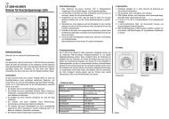
<strong>Möbel</strong>-<strong>Einbaustrahler</strong> /<br />
-<strong>Aufbaustrahler</strong><br />
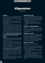
Stromschlaggefahr!<br />
Beauftragen Sie mit der Installation eine Elektro-Fachkraft.<br />
Für Strahler, die nicht gemäß den europäischen Sicherheitsrichtlinien<br />
installiert wurden, entfällt jeder Haftungsanspruch.<br />
Brandgefahr!<br />
Strahler nicht mit wärmedämmenden Stoffen<br />
abdecken.<br />
Mindestabstand zwischen Strahler und<br />
nächstgelegenem angestrahlten Gegenstand<br />
einhalten (siehe Zeichnung).<br />
Seitliche Mindestabstände<br />
einhalten<br />
(siehe Zeichnung). 50 mm 50 mm<br />
Verletzungsgefahr!<br />
Strahler niemals ohne eingebautes Schutzglas verwenden.<br />
Beschädigte Schutzgläser auswechseln.<br />
Achtung!<br />
Strahler ausschließlich mit Kabel HO3VVH2-F 2x0,75 mm<br />
an Transformator anschließen.<br />
Ausschließlich Halogenniederdrucklampen nach<br />
IEC 598 (EN60598) verwenden. Die Lampen<br />
müssen für den Betrieb in offenen Leuchten<br />
zugelassen sein. Technische Daten: max.<br />
10 W / 12 V / Sockel G4.<br />
Schutzklasse 3 – Niedervolt 12 V.<br />
Sicherheitstransformator nach EN 61558, elektronischen<br />
Konverter nach EN 61347 oder eine<br />
Spannungsquelle nach DIN VDE 0100, Teil 410<br />
verwenden. Für den Anschluss unbedingt Anleitung<br />
des verwendeten Gerätes beachten.<br />
Die Strahler ist zur Montage auf oder in <strong>Möbel</strong>n<br />
geeignet, die aus Werkstoffen mit unbekannten<br />
Entfl ammungseigenschaften bestehen. Strahler<br />
nur nach unten strahlend montieren.<br />
VDE-geprüft, CE-konform mit den zutreffenden<br />
europäischen Richtlinien.<br />
Montage<br />
Stromschlaggefahr!<br />
Vor der Installation Spannung abschalten. Sicherstellen,<br />
dass der Spannung nicht versehentlich wieder eingeschaltet<br />
werden kann.<br />
Strahler ohne Anschlussklemme. Für den Anschluss können<br />
Hinweise von Fachpersonen erforderlich sein.<br />
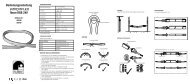
Bei <strong>Aufbaustrahler</strong>n eine separate Anschlussdose mit Anschlussklemme<br />
verwenden (siehe Abb. 1; nicht im Lieferumfang<br />
enthalten).<br />
1. <strong>Einbaustrahler</strong>: Loch an Montageort sägen 60 mm<br />
(Durchmesser siehe Zeichnung).<br />
<strong>Aufbaustrahler</strong>: Aufbauhalterung am<br />
Montage ort festschrauben.<br />
2. Transformator nach dessen Anleitung montieren. An die<br />
Eingangsseite 230-V-Leitung, an die Ausgangsseite 12-V-<br />
Leitung anschließen.<br />
3. Strahler und Transformator mit Anschlussklemme verbinden.<br />
4. Strahler in das ausgesägte Loch bzw. in den Aufbauring<br />
einsetzen.<br />
Lampen- / Schutzglas-Wechsel<br />
Stromschlaggefahr!<br />
Vor Lampen- oder Schutzglaswechsel immer Spannung<br />
abschalten.<br />
Achtung!<br />
Halogenlampe und Innenfl ächen des Refl ektors nicht mit<br />
bloßen Fingern anfassen. Durch Fettrückstände wird die<br />
Lebensdauer der Lampe erheblich eingeschränkt. Fusselfreies<br />
Tuch verwenden.<br />
<strong>Aufbaustrahler</strong> (Abb. 1) / <strong>Einbaustrahler</strong> (Abb. 2)<br />
• Nur <strong>Aufbaustrahler</strong>: Strahler nach unten aus dem Aufbauring<br />
herausziehen.<br />
1. Ring entgegen dem Uhrzeigersinn drehen (Bajonettverschluss)<br />
und abnehmen.<br />
2. Schutzglas wird an drei Punkten gehalten; vorsichtig herausnehmen.<br />
3. Lampe aus Sockel herausziehen.<br />
4. Neue Lampe einstecken.<br />
5. Schutzglas wieder einsetzen.<br />
6. Oberen Ring mit Aussparungen auf Nasen setzen und im<br />
Uhrzeigersinn festdrehen.<br />
Schwenkbarer <strong>Einbaustrahler</strong> (Abb. 3)<br />
1. Kunststoffring an der Naht nach innen drücken und herausnehmen.<br />
2. Schutzglas wird an drei Punkten gehalten; vorsichtig herausnehmen.<br />
3. Lampe aus Sockel herausziehen.<br />
4. Neue Lampe einstecken.<br />
5. Schutzglas wieder einsetzen.<br />
6. Kunststoffring zusammendrücken und wieder einsetzen.<br />
Abb. 1 Abb. 2 Abb. 3 (RU-05-05 / Redaktion: ZINDEL AG, www.zindel.de)<br />
rutec Licht GmbH & Co. KG<br />
Tel. (0 42 42) 95 65-0<br />
Fax (0 42 42) 95 65-25<br />
E-Mail: info@rutec.de<br />
http://www.rutec.de<br />
Carl-Zeiss-Str. 15<br />
28857 Syke<br />
Postfach 1437<br />
28848 Syke
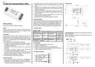
Furniture recessed /<br />
Furniture surface<br />
downlight<br />
Danger of electrocution!<br />
Be sure to have a professional electrician complete installation.<br />
There is no warranty coverage for any downlights<br />
installed without observing European safety directives.<br />
Fire hazard!<br />
Do not cover downlight with heat-insulating<br />
materials.<br />
Ensure that minimum clearance between<br />
the downlight and the nearest object<br />
which it is shining on is maintained (see<br />
drawing).<br />
Ensure that minimum<br />
clearance is also<br />
maintained on each 50 mm 50 mm<br />
side (see drawing).<br />
Danger of injury!<br />
Never use downlight without installed protective glass.<br />
Replace any damaged protective glass.<br />
Caution!<br />
Only connect downlight to a transformer using<br />
HO3VVH2-F 2x 0.75 mm cable.<br />
Use only low-pressure halogen lamps which<br />
comply with IEC 598 (EN 60598). The lamps<br />
must be permissible for use as exposed lamps.<br />
Technical specifi cations: max. 10 W / 12 V /<br />
G4 base.<br />
Protection class 3 – Low voltage 12 V.<br />
Use an isolating transformer complying with EN<br />
61558, electronic step-down convertor complying<br />
with EN 61347 or a voltage source complying<br />
with DIN VDE 0100, Part 410. Be sure to<br />
observe the instructions for installation of the<br />
device being used.<br />
The downlights are designed for surfacemounted<br />
or recessed installation in furniture<br />
which are built using materials having unknown<br />
ignition properties. Only install downlights so that<br />
they shine downwards.<br />
VDE-tested, CE compliant with the pertinent<br />
European standards.<br />
Installation<br />
Danger of electrocution!<br />
Switch off voltage prior to installation. Ensure that voltage<br />
cannot be accidentally switched on again.<br />
Downlights without terminal clamp. Instructions from<br />
professionally trained technicians may be necessary for<br />
making the connection.<br />
Use a separate terminal box with terminal clamp for furniture<br />
surface downlight (see Fig. 1; not included in delivery).<br />
1. Furniture recessed downlights: Saw a hole 60 mm<br />
at the installation location (see drawing for<br />
diameter).<br />
Furniture surface downlight: Screw mount<br />
into place at installation location.<br />
2. Install transformer based on the supplied instructions.<br />
Connect the 230V cable to the input side and connect the<br />
12-V cable to the output side.<br />
3. Connect downlights and transformer using the terminal<br />
clamp.<br />
4. Insert downlights in the sawed out hole or the mount fi xture.<br />
Changing lamps / protective glass<br />
Danger of electrocution!<br />
Always disconnect voltage before changing lamps or<br />
protective glass.<br />
Caution!<br />
Never touch halogen lamps or the inner surfaces of the<br />
refl ector with your bare hands. Fatty residue will<br />
considerably shorten the service life of the lamp. Use a<br />
lint-free cloth.<br />
Furniture surface downlight (Fig. 1) / Furniture recessed<br />
downlight (Fig. 2)<br />
• Only for furniture surface downlight: Pull the downlight<br />
downwards out of the mount fi xture.<br />
1. Turn the fi xture anticlockwise (quarter-turn fastener) and<br />
remove it.<br />
2. The protective glass must be held at three points; remove<br />
carefully.<br />
3. Take the lamp out of the socket.<br />
4. Insert a new lamp.<br />
5. Put the protective glass back in.<br />
6. Place the upper fi xture with the notches on the rounded<br />
tabs and tighten fi rmly by turning clockwise.<br />
Moveable downlight (Fig. 3)<br />
1. Press the plastic ring inwards on the seam and pull the<br />
plastic ring out.<br />
2. The protective glass is held at three points; carefully<br />
remove.<br />
3. Take the lamp out of the socket.<br />
4. Insert a new lamp.<br />
5. Put the protective glass back in.<br />
6. Press the plastic ring together and put it back into place.<br />
Fig. 1 Fig. 2 Fig. 3 (RU-05-05 / Edited by: ZINDEL AG, www.zindel.de)<br />
rutec Licht GmbH & Co. KG<br />
Phone: +49 (0) 42 42 95 65-0<br />
Fax: +49 (0) 42 42 95 65-25<br />
E-mail: info@rutec.de<br />
http://www.rutec.de<br />
Carl-Zeiss-Str. 15<br />
28857 Syke,<br />
Germany<br />
PO Box 1437<br />
28848 Syke,<br />
Germany