AlphaCom E - Zenitel
AlphaCom E - Zenitel
AlphaCom E - Zenitel

You also want an ePaper? Increase the reach of your titles
YUMPU automatically turns print PDFs into web optimized ePapers that Google loves.
Revised May 2009<br />
STENTOFON <strong>AlphaCom</strong> E (IP)<br />
Security Communications System<br />
A & E GUIDE SPECIFICATIONS<br />
PART I: GENERAL<br />
1.1. WORK INCLUDED<br />
A. Furnish and install a complete microprocessor controlled, "duplex" voice communication system as<br />
described herein and shown on the plans. The system shall include a digital central exchange and all<br />
necessary boards, power supplies, master control stations, substations, receptacles, special<br />
mounting boxes, loudspeakers terminal boards, cable, connectors, and accessories for a complete<br />
operational communication system.<br />
B. Scope of work shall include the on-site SECURITY COMMUNICATION SYSTEMS, including all<br />
intercoms, with access to audio paging, the telephone system, CCTV video switchers, alarm systems<br />
and access control security systems as shown on the plans.<br />
1.2. CONTRACT DOCUMENTS<br />
(Note to specifier: Indicate exact scope of work)<br />
A. All equipment and work specified in this section shall comply with all the General Conditions of the<br />
specifications, contract documents, and drawings as indicated.<br />
1.3. RELATED WORK<br />
A. Systems shall be installed by a qualified Security Communications Contractor, who shall coordinate<br />
all work with other contractors and trades.<br />
B. All necessary conduit, raceways, pull boxes, standard boxes, (and special boxes provided by<br />
intercom manufacturer), shall be installed by the electrical contractor.<br />
C. Installation of the communication systems shall be coordinated with the installation of other related<br />
systems such as: C.C.T.V video switching, audio paging, access control, two-way radio, alarm and<br />
telephone systems.<br />
1.4. QUALITY ASSURANCE<br />
(Note to specifier: Indicate other related systems)<br />
A. Installation shall comply with all applicable codes.<br />
B. All equipment shall be new, in current production, and the standard products of a manufacturer of<br />
intercom equipment. Manufacturer shall be certified as complying with the standards of ISO-9001 for<br />
quality control. The central exchange shall meet standards and be certified with a CE label as<br />
conforming to rigid EMC requirements for electromagnetic emissions, immunity and harmonics.<br />
STENTOFON/<strong>Zenitel</strong> Group - 6119 Connecticut Ave. – Kansas City, MO 64120 – 816/231-7200 – 800/654-3140 – Fax: 816/231-7203 – www.zenitelusa.com<br />
- 1 -
Revised May 2009<br />
C. Manufacturer shall guarantee availability of parts, for a minimum of (_7_) years from date of<br />
shipment.<br />
D. If required, manufacturer shall be able to demonstrate features, functions, operating characteristics<br />
and clarity of sound to owner.<br />
E. System shall be installed by a factory authorized communications contractor with technicians<br />
specifically trained on this system.<br />
F. On-site maintenance and repair service shall be available locally and within (_4_) hours of notification<br />
for emergency conditions.<br />
G. System shall allow remote programming. Manufacturer shall have the ability to access and make<br />
changes to the system via IP connectivity.<br />
1.5. WARRANTY<br />
A. System shall include a factory warranty that equipment is free from defects in design, material,<br />
manufacturing and operation.<br />
B. Factory warranty period shall be for 36 months from date of shipment.<br />
C. Installing communications contractor shall guarantee the equipment, wire, cable, and installation for<br />
12 months from date of acceptance.<br />
1.6. SUBMITTALS<br />
A. Shall include an equipment list, and data sheets, system description and block diagrams on<br />
equipment to be furnished.<br />
B. Shall include all data necessary to evaluate design, function, quality, and configuration of proposed<br />
equipment and system(s).<br />
STENTOFON/<strong>Zenitel</strong> Group - 6119 Connecticut Ave. – Kansas City, MO 64120 – 816/231-7200 – 800/654-3140 – Fax: 816/231-7203 – www.zenitelusa.com<br />
- 2 -
Revised May 2009<br />
PART II: PRODUCTS<br />
2.1. ACCEPTABLE MANUFACTURERS<br />
A. The system as described herein is based on the STENTOFON ® ALPHACOM EVOLUTION (E-Series)<br />
intercom system manufactured by <strong>Zenitel</strong> USA, Kansas City, Missouri. The ALPHACOM system<br />
meets requirements of the specifications and shall be considered as the acceptable Base Bid.<br />
B. Substitutions must meet requirements of Prior Approval, as outlined in the contract documents.<br />
Substitutions that meet Prior Approval requirements must be listed as alternates by addendum, and<br />
shall be shown separately on the bid forms. Consideration will be based on ability to comply with all<br />
aspects of the specifications, the desired functional operation, quality, reliability, design, size, and<br />
appearance of the equipment and the support capabilities of the manufacturer.<br />
2.2. SYSTEM DESCRIPTION<br />
A. The purpose of the SECURITY COMMUNICATION SYSTEM shall be to provide fast “duplex,”<br />
(hands-free at both ends) voice communication as required to provide instant intercommunications<br />
for employees and visitors, emergency paging and signaling, alarm distribution and audio program<br />
distribution. System shall assist with personnel safety, facility security, security systems integration,<br />
operational efficiency and maintenance functions.<br />
B. The system shall be a microprocessor controlled system running embedded real time Linux, fully<br />
"digital", PC programmable, central switching exchange type using individual (2) twisted pair cable<br />
from the exchange to each station. The system shall be capable of automatic “duplex,” hands-free<br />
operation, without the use of handsets, at both the initiating and receiving station, and each station<br />
shall include a condenser microphone and preamplifier. The exchange shall include 2 Ethernet IP<br />
ports which can support protocols IP v4-IP v6, TCP, UDP, Telnet, FTP, NTP, HTTP 1.1, Syslog,<br />
SNMP v2c, SIP, RTP, RTCP, VoIP AlphaNet and 2 serial data ports, RS-232, RS-422 and RS485<br />
type, both input and output, for direct transfer of call processing functions to and from other<br />
<strong>AlphaCom</strong> and <strong>AlphaCom</strong> Evolution (E-Series) exchanges as well as to external microprocessor<br />
controlled equipment such as access control, CCTV switchers, remote control boards and audio<br />
amplifiers. The exchange shall support the mix of IP and traditional stations as desired. The<br />
exchange shall support SIP protocol to allow for interfacing to VoIP telephones and or systems and<br />
equipment. The system shall provide special features such as the capability of redundancy via IP,<br />
wideband audio (7kHz), built in firewall, integrated web & SIP server as well as low latency switching.<br />
The exchange shall allow for remote programming, logging and maintenance via IP using AlphaPro<br />
as well as additional maintenance and statistical information via IP using web browser to interface to<br />
AlphaWeb.<br />
C. System capacity shall include a modular central exchange cabinet(s) for__________ wired stations<br />
and or ___________ IP stations and _____speech channels. System shall be expandable by adding<br />
plug-in boards, analog stations, IP stations and software licenses and modules to approximately<br />
140,208 stations. The system shall be expandable to AlphaNet operation with remote sites, using<br />
transparent dialing between remote modules.<br />
(Note to specifier: indicate size and capacity of exchange(s)<br />
D. The scope of the system shall include all features and functions described herein and the equipment<br />
shown on the plans. System shall be capable of adding optional features, equipment and interfaces<br />
listed in the specifications, even if not initially included or shown on the plans.<br />
STENTOFON/<strong>Zenitel</strong> Group - 6119 Connecticut Ave. – Kansas City, MO 64120 – 816/231-7200 – 800/654-3140 – Fax: 816/231-7203 – www.zenitelusa.com<br />
- 3 -
Revised May 2009<br />
E. A complete operational system shall be provided. The system functions in public areas such as<br />
elevators, lobbies and parking areas shall comply with ADA requirements.<br />
2.3. SYSTEM CONFIGURATION<br />
A. The central exchange(s), power supplies, batteries, interfaces, page adapters, accessories, and main<br />
distribution board, shall be located in an appropriate secure data processing room, separate from the<br />
telephone equipment room (as shown on the plans).<br />
B. The central exchanges(s) may or shall be configured in AlphaNet configuration and connected via IP<br />
to customers LAN/WAN or internet and be able to be connected in such a matter to create a single<br />
system that can consists of up to 254 <strong>AlphaCom</strong> E system nodes. All necessary data and audio<br />
routing between <strong>AlphaCom</strong> E exchanges shall be via IP and only require the necessary AlphaNet<br />
VoIP software licenses based on the system design. No additional hardware boards or proprietary<br />
black boxes will be necessary to do the networking via IP between <strong>AlphaCom</strong> E exchanges.<br />
C. System shall consist of duplex master stations with direct access buttons, with or without handsets,<br />
and with or without LCD displays, as indicated on the plans. Each master shall be capable of calling<br />
all other stations in the system unless specifically blocked or restricted through programming. System<br />
shall be capable of having both traditional and IP based stations along with SIP stations to meet the<br />
needs of the system design.<br />
D. Security control room masters, and all other master stations shall be desk, flush or surface wall<br />
mounted, or rack mounted as shown on the plans.<br />
E. Substations shall be flush or surface mounted, tamper and weather resistant where needed and<br />
located as required for direct access calling to control room masters, as shown on the plans. The<br />
elevator company shall install elevator car substations.<br />
F. System shall include a "supervisor's" display type master control station at or near the central<br />
exchange to function as a system maintenance and fault indication station.<br />
G. All features and functions shall be programmed on site with a standard PC via IP.<br />
(Note to specifier: Indicate project requirements)<br />
2.4. STANDARD SYSTEM FEATURES<br />
A. MASTER CALLS. A call shall be placed from any master station to any other station in the system,<br />
unless specifically blocked, by dialing the appropriate number of the desired station, or using one of<br />
the direct access buttons. Either party can cancel call by pressing the (C) button.<br />
B. SUBSTATION CALLS. Each substation shall be programmed to call a specific master station(s).<br />
Pressing button on substation shall provide call request verification by blinking LED on station and<br />
giving voice message (with optional voice board). A substation “call-request” call shall be identified on<br />
a display master, with text message, or flash an associated LED and sound a unique tone on a CRM<br />
type control room master.<br />
STENTOFON/<strong>Zenitel</strong> Group - 6119 Connecticut Ave. – Kansas City, MO 64120 – 816/231-7200 – 800/654-3140 – Fax: 816/231-7203 – www.zenitelusa.com<br />
- 4 -
Revised May 2009<br />
C. DIRECT ACCESS BUTTONS. All desk master stations shall include (10) direct access buttons,<br />
programmed for direct access calling, to allow single button speed dialing of other stations, features<br />
or telephone lines. Station user shall easily program direct access buttons at any time. Control room<br />
masters (CRMIV) shall have button modules available in (48) direct access button size with each<br />
CRMIV capable of up to 96 direct access buttons. Dual Display Master Stations (7007) shall be<br />
capable of up to 90 direct access buttons.<br />
D. ALL-CALL. All master stations shall be able to initiate an all-call page to all other stations in the<br />
system. It shall be possible to remove stations, through programming, from receiving all-call and<br />
restrict any station from initiating an all-call. Selected stations shall receive all-call announcements at<br />
full volume, regardless of station volume setting.<br />
E. GROUP-CALL. All master stations shall be able to initiate selective paging to predetermined groups<br />
of stations in the system. Ability to initiate group call shall be restricted to designated stations. A<br />
station may be programmed for membership in several groups. It shall be possible to program up to<br />
100 groups. There shall be no limitations to the number of stations in any group. It shall be possible to<br />
program up to eight adjacent stations out of a group call so as to eliminate audio feedback. The<br />
system shall be able to send out several group calls simultaneously. With up to 4 levels of priority.<br />
Each group shall be able to program one of 4 call announce chime tones.<br />
F. OVERHEAD PAGING. All master stations shall be able to dial or direct access into one, or more,<br />
voice paging system(s) for zoned and/or department paging over amplified speakers, unless<br />
specifically restricted through programming.<br />
G. AUTOMATIC SEARCH FEATURE. Each station shall have a pre-programmed list of actions that can<br />
automatically take place when their station is called but they are either busy, private, absent or<br />
unattended call request. System shall allow call to be automatically rerouted to another station, call<br />
request, group call etc. Each station can have up to 3 different search call numbers.<br />
H. REPLY FEATURE. A person hearing a page or group call shall be able to begin an immediate normal<br />
hands free conversation with the person who initiated the page, by simply pressing an answer code,<br />
99, on any convenient master station in the group. System shall allow multiple page/reply functions<br />
simultaneously. The waiting time shall be programmable.<br />
I. DUPLEX/MANUAL OPERATION. Once call connection is established, normal conversation shall take<br />
place in the “duplex” mode, whereby each person may talk “hands-free.” Each master shall have a<br />
manual “M” button that when used shall control the direction of the conversation (press to talk,<br />
release to listen). Momentarily depressing "M" button shall restore duplex mode.<br />
J. REMOTE CONTROL FUNCTIONS. Each station port in the exchange shall include (1 RCO (Remote<br />
Control Output) to be freely used for control of external equipment. <strong>AlphaCom</strong> Relay Board 99702<br />
required. See Options.<br />
K. VOLUME CONTROLS. The volume of each station shall be adjustable by programming the<br />
appropriate subscriber board in the exchange, either from the station or from PC programming. In<br />
addition, each master shall have an adjustable slide-switch volume control. Adjustments shall allow a<br />
total range of: (-14 dB to +16 dB). Outgoing volume shall be automatically increased by +6 dB when<br />
using the M key for press-to-talk.<br />
L. TONE SIGNALS. All features and functions such as: off hook, call connection; busy; call forward; all<br />
call; group call; etc., shall be accompanied or preceded by a distinguishable tone. All/Group Call tone<br />
signals shall be programmable, and tones shall be harmonic and undistorted. It shall be possible to<br />
customize and change the length and frequency of All/Group tones.<br />
STENTOFON/<strong>Zenitel</strong> Group - 6119 Connecticut Ave. – Kansas City, MO 64120 – 816/231-7200 – 800/654-3140 – Fax: 816/231-7203 – www.zenitelusa.com<br />
- 5 -
Revised May 2009<br />
M. MICROPHONE MUTE. During a conversation, a person shall be able to momentarily block the<br />
microphone on any master by holding down one button (the "0" key).<br />
N. CALL HOLD, INQUIRY & TRANSFER. Once a call is connected, it shall be possible to place the call<br />
on "hold" by pressing one button (digit #2), dialing and conversing with a third party, switching back<br />
and forth or transferring the call by pressing one button (#3).<br />
O. STANDARD CONFERENCE. It shall be possible to establish and/or join a conference by dialing a<br />
four-digit code. It shall be possible to include any number or all stations in a conference. The system<br />
shall be capable of 50 conferences. Voice control shall be manual, (press-to-talk, release-to-listen). In<br />
a standard conference, intercom and paging announcements shall temporarily interrupt the<br />
conference. One person at a time shall talk in an individual conference. Stations can be programmed<br />
with the ability to override and take control of talking into or speaking into the conference.<br />
P. PRE-SET GROUP CONFERENCE. It shall be possible to set up a group conference by simply dialing<br />
a two-digit code, then a group number followed by the conference number. System shall allow up to<br />
50 conference groups. Dialing the pre-set group conference number shall include all members of the<br />
group, and all members of the group shall be able to hear whoever is talking. Each group member<br />
shall be able to speak to the group by holding down the [M] button on his master. It shall be possible<br />
to have a pre-set conference automatically activated by a remote alarm contact. One person at a time<br />
shall talk in an individual conference. Certain stations can be programmed with the ability to override<br />
and take control of talking into or feeding the conference.<br />
Q. OPEN DUPLEX CONFERENCE. It shall be possible to set up an open duplex conference by simply<br />
dialing a four-digit code. It shall be possible to have 20 different conferences. Upon dialing the code<br />
the station will start ringing, by lifting the handset you will enter the conference. By placing handset<br />
back on hook you will leave the conference. If you wish to rejoin the open duplex conference you<br />
simply dial the four-digit code. It shall be possible to start a preset open duplex conference to include<br />
a preset group of stations. It shall also be possible to program DAK Keys on stations to allow for<br />
single button dialing to enter conference and also start a preset conference. The number of<br />
participants in an open duplex conference is typically 4 stations, but by programming an open duplex<br />
conference can have more stations if desired.<br />
R. PRIORITY AND CLASS OF SERVICE. System shall have 4 levels of priority to allow or deny access<br />
to features, such as voice or pocket paging, all-call, group-calls, preset conferences, tie-lines,<br />
telephone lines, special interfaces, groups of stations and text display of alarm messages. System<br />
shall include 16 classes of service which shall allow the ability to customize features/functions<br />
available to stations.<br />
S. DO-NOT-DISTURB. All master stations shall be equipped with a privacy/open switch to permit any<br />
user to put his station in the "privacy" mode. When in the privacy mode, an incoming call shall sound<br />
a unique "privacy ring tone" at both the initiating station and station being called. Call may be<br />
answered by pressing the "M" button. It shall be possible to program selected stations with "Privacy<br />
Override", whereby calls will be heard even if stations are in the privacy mode.<br />
T. STATION NUMBERING. System shall have a true flexible numbering plan feature, whereby any<br />
number from “0” to “999999” may be assigned to stations or feature codes. Dialing between remote<br />
exchanges shall be transparent. Shall be factory programmed with an “autoload” numbering plan of<br />
up to 650 separate numbers that may be changed on-site as required. It shall be possible to change<br />
numbers any time through programming, with access codes, without any rewiring.<br />
STENTOFON/<strong>Zenitel</strong> Group - 6119 Connecticut Ave. – Kansas City, MO 64120 – 816/231-7200 – 800/654-3140 – Fax: 816/231-7203 – www.zenitelusa.com<br />
- 6 -
Revised May 2009<br />
U. MUSIC DISTRIBUTION. System shall allow up to 6 channels of music to be distributed to all stations.<br />
Each master may select a desired channel by simply dialing a three-digit code. Music shall be<br />
interrupted during intercom calls and return automatically upon completion of the call. System shall<br />
also include a “channel step” function. Thirty-two additional channels shall be available through<br />
optional boards. Note: Standard for <strong>AlphaCom</strong> E7 is two channels. Optional board 9301 APC Filter<br />
Connection Package must be used for <strong>AlphaCom</strong> E26.<br />
(Note to specifier: Indicate if music distribution is required for system.)<br />
V. INFORMATION CHANNEL. System shall allow one or more audio channels to be programmed to<br />
distribute audio information that is pertinent to the operation of the facility. Channel shall be accessed<br />
and operate as described for music distribution.<br />
W. REMOTE SET UP OF PROGRAMS. It shall be possible to individually program stations, or groups of<br />
stations to receive a channel from a remote master control station.<br />
X. TEXT MESSAGES. The system shall allow multiple alpha/numeric text messages to be stored in<br />
queue on each master. The sequence of display shall be based on the priority of each message.<br />
System shall include (9) absent, (9) functional and (3) alarm messages.<br />
Y. TECHNICAL ALARMS. It shall be possible to activate a preset (16) character text message on a<br />
selected display master, group of masters or activate an audio message on the information channel,<br />
from remote alarm contacts. Each message can be customized and set with a priority level through<br />
programming. The system shall include (6) inputs for technical alarms. Note: Standard for <strong>AlphaCom</strong><br />
E7 is two inputs. Optional board 9301 APC Filter Connection Package must be used for <strong>AlphaCom</strong><br />
E26 & E20’s.<br />
(Note to specifier: Indicate if music distribution is required for system.)<br />
Z. AUDIO ALERT OF TEXT MESSAGE. System shall allow (4) distinct types of audible alert tones to<br />
sound at the master, when messages are activated. Shall also allow connection of external alarm<br />
indicators (lamps, buzzers or bells) to sound for high priority messages in noisy environments.<br />
AA. CALL REQUESTS TO MULTIPLE MASTERS. It shall be possible to program up to (20) masters to<br />
simultaneously receive and display text message call requests from substations. When the calls are<br />
answered at one master, the messages shall be deleted from all other masters. It shall also be<br />
possible if receiving a call request with a certain high priority level to alert receiving station(s) by a<br />
private ringing tone.<br />
BB. TRANSFER OF CALL REQUESTS. It shall be possible to transfer call requests from substations<br />
(while allowing standard calls) to different masters by simply dialing a (4) digit transfer code plus the<br />
number of the master or group of masters that will receive the transferred calls.<br />
CC. TRANSFER OF STANDARD CALLS. It shall be possible to redirect (Call Forward) "all" calls to<br />
another master, a pager number, telephone number, or group number simply by dialing a two-digit<br />
code 71, plus the redirected number. When in the "transferred" mode, only the station selected to<br />
receive the diverted calls shall be able to call or transfer calls to the forwarded station. It shall also be<br />
possible to redirect calls while at the receiving station (Follow me) by dialing a two-digit code 72 plus<br />
the number of the forwarded station. The system shall be able to simultaneously handle up to (100)<br />
call forward commands.<br />
STENTOFON/<strong>Zenitel</strong> Group - 6119 Connecticut Ave. – Kansas City, MO 64120 – 816/231-7200 – 800/654-3140 – Fax: 816/231-7203 – www.zenitelusa.com<br />
- 7 -
Revised May 2009<br />
DD. “CAMP-ON” BUSY. The system shall include ability to call a busy station, or feature, hear a busy tone<br />
(reduced in volume after 5 seconds), wait for a preset time and automatically connect when the called<br />
station or feature is free. Upon connection, both parties shall hear the normal “connection tone.”<br />
Number of “camp-on” calls in the system shall be unlimited.<br />
EE. TEXT CALL BACK MESSAGE. If the calling party does not wish to remain “camped-on,” it shall be<br />
possible to place the call in memory and display a callback message on the called party's station by<br />
dialing an additional digit [8]. The message shall be registered on the display. It shall be possible to<br />
leave up to 9 pre-set text messages on the display of the called station. The number of “call-back<br />
messages” on any one station, or in the whole system, shall be unlimited.<br />
FF. VOICE CALL-BACK MESSAGE. It shall be possible to leave a "pre-set" audio voice message, by<br />
dialing a voice message code 7 on the initiating intercom station. The audio message shall be played<br />
back at the receiving station by dialing two digits 70. Voice messages shall require 9304 ASVP board<br />
in the exchange (see options).<br />
GG. GROUP HUNT. The system shall allow programming of multiple "Hunt" groups, whereby calls to a<br />
group number will search and connect to the first available station in the group. The feature may be<br />
programmed to have a rotational or fixed start point. Feature shall allow substation calls to be<br />
directed to a primary master but if it is busy, search for an available master in the group. Shall allow<br />
automatic transfer on busy.<br />
HH. CALL REQUEST TRANSFER “PRESET.” Stations shall be allowed to automatically divert call<br />
request calls to a pre-selected station or group of stations simply by dialing a pre-set code [7870],<br />
then the station number or group number.<br />
II.<br />
JJ.<br />
SOFTWARE PROTECTION. All programmable information, including customer on-site changes, shall<br />
be retained in FLASH memory. In addition, it shall be possible to store the program on a PC using<br />
AlphaPro and also be able to download via AlphaWeb the contents of the FLASH memory as a file for<br />
troubleshooting.<br />
EMERGENCY ALARM CALLS. Selected stations shall be able to initiate priority alarm calls to groups<br />
of stations in the system. Alarm calls shall override all conversations in progress, override station<br />
volume settings, and be heard even if handset is off-hook on desk master stations. Stations can be<br />
exempt from receiving the emergency calls. In addition, it shall be possible to initiate an alarm call<br />
from external equipment and give an automatic voice message.<br />
KK. WAKE UP REMINDER CALLS. The system shall allow (200) separate automatic date and time calls<br />
that will cause individual stations to ring at preset times. This wake up time is entered at the selected<br />
station itself. The duration and number of rings shall be programmable. After initiation, dialing a digit<br />
or lifting the handset shall cancel the ring.<br />
LL.<br />
FAULT/ALARM LOGGING. System shall archive via Syslog file fault conditions within the system<br />
(faulty boards, wiring or software), and external alarm conditions input through the intercom system<br />
(prints time and source of alarm) as well as call logging between intercom stations for the entire<br />
system. It shall also be possible to view via AlphaWeb the Syslog file to inspect the contents of the<br />
file. Using an OEM Syslog viewer shall allow for faults/alarm logging and call logging events to be<br />
sent to remote/external IP address for remote monitoring of the system and also the possibility to<br />
send these events via Syslog viewer to an email address.<br />
STENTOFON/<strong>Zenitel</strong> Group - 6119 Connecticut Ave. – Kansas City, MO 64120 – 816/231-7200 – 800/654-3140 – Fax: 816/231-7203 – www.zenitelusa.com<br />
- 8 -
Revised May 2009<br />
MM. ALARM OVERIDE. System shall allow priority calls and voice alarm messages to override standard<br />
intercom calls and come through speaker at full volume, even when handset is in use, privacy switch<br />
on and volume set low.<br />
NN. TONE TEST. System shall have the capability to do a tone test of entire system. This tone test shall<br />
test the speaker and microphone circuits of all standard stations. This test can be performed<br />
automatically everyday at a certain time or can be manually started to provide a system evaluation for<br />
troubleshooting purposes. The results of the tone test are sent to Syslog file and are saved so results<br />
can be looked at a later time that is convenient via AlphaWeb.<br />
OO. HOTLINE CALL. System shall have the ability from any master station to perform a hotline call. This<br />
hotline call is performed by lifting the handset on a master station, which in turn will place a call to a<br />
station or feature that is programmable per station in 5 seconds. Default timer of 5 seconds is<br />
programmable, however this is a system wide timer for all stations.<br />
PP. EVENT HANDLING. Programming of custom scripts allows for custom software functions or features<br />
that are not provided in the basic system. These special features can include actions such as ASCII<br />
data outputs strings to external computers for interfacing to CCTV or card access or specific events<br />
related to transfers, call requests to multiple stations in multiple exchanges simultaneously and many<br />
other non standard features that a customer desires that are unique to or needed for their intercom<br />
system.<br />
QQ. SIP INTERFACE. This interface shall provide the ability for VoIP telephones or telephone systems<br />
which support SIP protocol to interface and register to the <strong>AlphaCom</strong> E-series exchange. VoIP<br />
telephone can be a single IP telephone device or can be a soft phone client running on a PC. This<br />
interface allows for point to point calling between any intercom station and SIP telephone devices with<br />
call number and text shown on both ends of the call. Requires #9643-XXX SIP license(s) which is<br />
dependent on the number of SIP users required. IP SIP capable phone by others, consult <strong>Zenitel</strong> for<br />
recommended models that have been tested for use with the <strong>AlphaCom</strong> E system.<br />
2.5. SYSTEM OPERATION<br />
(Note to specifier: Indicate if SIP Protocol is required for system.)<br />
A. MASTER-TO MASTER CALLS. All masters shall be able to call all other masters individually, point to<br />
point, unless blocked through programming, by simply touch dialing a 1-6 digit number, or by using<br />
direct access buttons. Once dialed, both stations shall be able to converse "hands free". All standard<br />
features listed shall be available to all masters.<br />
B. CALL FROM SECURITY SUBSTATION TO CRM MASTER. A call request shall be initiated from a<br />
substation by activating an alarm button, or the call-in button on the substation. The call request shall<br />
indicate to the calling party with a flashing green LED (and an audible call acknowledgment voice<br />
message) to comply with ADA (see options). It shall be possible to also start an external strobe light<br />
(see options). This call request shall be annunciated at the CRMIV Control Room Master station as<br />
follows:<br />
1. The LCD will show you have received a call request from a station.<br />
2. A rapidly repeating tone signal sounds. Call request shall be answered at the CRMIV by pressing<br />
appropriate direct access button preprogrammed to answer all call requests from stations.<br />
3. When call is answered the following shall occur:<br />
a. A connection tone is heard at both the CRM and the calling station.<br />
STENTOFON/<strong>Zenitel</strong> Group - 6119 Connecticut Ave. – Kansas City, MO 64120 – 816/231-7200 – 800/654-3140 – Fax: 816/231-7203 – www.zenitelusa.com<br />
- 9 -
Revised May 2009<br />
b. The flashing green LED illuminates "solid" on the appropriate button if direct dial unit (D48) is<br />
used.<br />
c. The Number and Text of the station that is connected appears in the LCD.<br />
d. An in-use LED illuminates on the calling substation.<br />
e. Clear, two-way communication shall take place.<br />
f. Other calls from substations to the CRM station shall each flash their appropriate direct access<br />
button LED if direct dial unit (D48) is used and sound the call-in tone.<br />
C. CALL FROM A CRM STATION TO ANY OTHER STATION. A call shall be placed from a CRMIV<br />
station to any other station in the system by simply dialing the station number on the digit keypad.<br />
LCD on the CRMIV station shall indicate the number and text of the called station. When calling any<br />
other master station, “duplex” hands-free communication shall be possible between the two stations.<br />
When calling an elevator car, or other security substation, the press-to-talk button shall be used to<br />
control the conversation, if needed.<br />
D. GROUP CALL FROM A CRM STATION. A group call shall be initiated at a CRMIV by dialing the<br />
number assigned to preprogrammed group of stations. This shall sound an alert tone and allow<br />
paging to all stations in the group. There shall be no limitation to the quantity of stations in a group.<br />
Group calls shall have priority over other conversations in progress.<br />
E. PROGRAMMING BUTTONS ON THE CRM STATION. Direct access buttons on the CRMIV master<br />
station shall be easily programmed and changed by the station user. Once programmed, the button<br />
assignments shall remain in memory. This feature is valid if CRMIV is equipped with D48 button<br />
modules.<br />
(Note to specifier: Describe other desired operations)<br />
STENTOFON/<strong>Zenitel</strong> Group - 6119 Connecticut Ave. – Kansas City, MO 64120 – 816/231-7200 – 800/654-3140 – Fax: 816/231-7203 – www.zenitelusa.com<br />
- 10 -
Revised May 2009<br />
2.6. EQUIPMENT AND PRODUCTS<br />
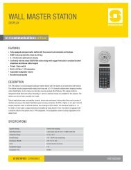
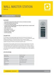
A. STANDARD DESK MASTER. Master shall include the following controls: dialing buttons 0-9; Manual<br />
“M,” button for speech control and other functions; cancel “C” button; privacy slide switch and variable<br />
volume control. Shall include 10 direct access buttons. Shall include a 3", 63 ohm, 1.6 watt speaker<br />
with a sensitivity 88 dB, mounted in an acoustic baffle. Shall include an electret condenser<br />
microphone with 100/300 mV output and sensitivity of -65 dB @1 kHz. Shall include a preamplifier<br />
with a 600 ohm output impedance, and greater than 40 dB signal to noise ratio. Frequency response<br />
of input and output shall be 300 to 10,000 Hz. Master shall be in a modern gray and black plastic<br />
housing, suitable for desk mounting, and have a six foot cord and plug. Shall be Stentofon #70362.<br />
70362<br />
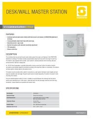
B. DESK MASTER WITH HANDSET. Master shall include the following controls: dialing buttons 0-9;<br />
Manual “M,” button for speech control and other functions; cancel “C” button; privacy slide switch and<br />
variable volume control. Shall include 10 direct access buttons. Shall include a 3", 63 ohm, 1.6 watt<br />
speaker with a sensitivity 88 dB, mounted in an acoustic baffle. Shall include an electret condenser<br />
microphone with 100/300 mV output and sensitivity of -65 dB @1 kHz. Shall include a preamplifier<br />
with 600 ohm output impedance, and greater than 40 dB signal to noise ratio. Frequency response of<br />
input and output shall be 300 to 10,000 Hz. Master shall be in a modern gray and black plastic<br />
housing, suitable for desk mounting, and have a six foot cord and plug with addition of a lightweight<br />
handset for confidential conversations. Color shall be black and gray. Shall be Stentofon #70342.<br />
70342<br />
C. WALL MOUNT STANDARD MASTER. Shall function exactly like a standard desk master but with all<br />
controls, speaker and microphone mounted on an extruded aluminum face plate, suitable for wall<br />
mounting. Shall include a sensitive condenser microphone and a 3" round, 63 ohm speaker with a 5<br />
ounce magnet. Finish shall be anodized aluminum. Mounts on #6020 flush or #6031 surface backbox.<br />
Shall be Stentofon #7040 and #7042 or #7045US.<br />
7040 7042 7045US<br />
STENTOFON/<strong>Zenitel</strong> Group - 6119 Connecticut Ave. – Kansas City, MO 64120 – 816/231-7200 – 800/654-3140 – Fax: 816/231-7203 – www.zenitelusa.com<br />
- 11 -
Revised May 2009<br />
D. OPERATING ROOM MASTER. Designed for hospital operating rooms. Master shall include a<br />
standard 0-9 keypad, manual “M” button, “C’ cancel button and LED call placed indicator. Shall<br />
include a sensitive condenser microphone and a 3" round, 63 ohm and 1.6 watt speaker display. The<br />
70366 Model shall have (4) programmable direct access buttons and LCD display. Shall have a Mylar<br />
covering for wipe-down sterilization. Mounts on #6020 flush or #6031 surface backbox. Size: 11" H x<br />
4.9" W x 2.6" D; Microphone: 100/300 mV output, -65 dB @ 1 kHz sensitivity; Speaker: 3" round, 63<br />
ohm, 1.6 watt, 88 dB sensitivity; Frequency: Voice range of 300-5,000 Hz; Mounts on #6020 flush<br />
wall box or #6031 surface box. Shall be Stentofon #60366 or #70366.<br />
60366 70366<br />
E. DESK DISPLAY MASTER. Master shall include a standard 0-9 keypad, manual “M” button, “C’<br />
cancel button, privacy/open slide switch, LED call placed indicator, variable volume control, (10)<br />
programmable direct access buttons and a 2 1/2" x 1/2", and a 16 character LCD alphanumeric<br />
display. Shall include a 3", 63 ohm 1.6 watt speaker with a 5 ounce magnet mounted in an acoustic<br />
baffle. Shall include an electric condenser microphone with a 100/300 mV output and sensitivity of -65<br />
dB @ 1 kHz. Shall include preamplifier with 1000 ohm output impedance and frequency range of 300<br />
to 10,000 Hz. Housing shall be ABS plastic finished suitable for desk or surface wall mounting.<br />
Dimension shall not exceed 3" H x 7" W x 7" D. Shall be Stentofon #7071 (Black).<br />
7071<br />
F. DISPLAY MASTER WITH HANDSET. Shall be identical to the 7071 Display Master, with addition of a<br />
handset, coiled cord and magnetic hook-switch. Shall be Stentofon #7072 or #7070 (Black).<br />
7072 7070<br />
STENTOFON/<strong>Zenitel</strong> Group - 6119 Connecticut Ave. – Kansas City, MO 64120 – 816/231-7200 – 800/654-3140 – Fax: 816/231-7203 – www.zenitelusa.com<br />
- 12 -
Revised May 2009<br />
G. DUAL DISPLAY MASTER. Master shall include a 10 direct access keys (DAK) keypad, divided into 9<br />
pages with information text for each DAK on a 5-8 character display. The station dialing keys shall<br />
have letters to be used for search facility in the intercom directory and display text editing. The station<br />
shall have 4 specific navigation keys for quick access to system menus and directory entries. Status<br />
information, guidance and menus are shown on a large 4 line graphic display. Frequency response<br />
of input and output shall be 300 to 7,000 Hz. Housing shall be ABS plastic finished suitable for desk<br />
mounting. Dimension shall not exceed 2.8" H x 5.5" W x 10.6" D. Shall be Stentofon #7007 (Black).<br />
7007 with/without gooseneck<br />
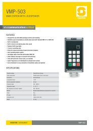
H. LIGHT INDUSTRIAL MASTER STATION. The light industrial master station shall be splash proof and<br />
designed for humid, dirty and outdoor conditions. The exterior casing shall be comprised of a flame<br />
and chip resistant Bayblend plastic with a UV cured, chemical resistant PVC front panel. This station<br />
shall have a red LED indicator for incoming calls and station in use indication. This station shall have<br />
an IP54 classification. Temperature Range: 0° to +50°C (+32°F to +122°F; Humidity Range: 10% -<br />
85% RH ; Dimensions: 4.9” x 9.5” x 2.5”; Sound Pressure at 1m from internal speaker: 66 db (0.5<br />
mm cable x 100 m, 8.0V on subscriber board, 1 kHz); Max. loudspeaker output - external speaker:<br />
1.5W (20 Ohm) 10W (8 Ohm) w/power amplifier; Frequency Range: 500-5,000 Hz (+ 8 dB) Gland<br />
Diameter: 1 x PG9, 1 x PG11; Shall be Stentofon #7080.<br />
7080<br />
I. NOISE CANCELLING INDUSTRIAL MASTER STATION. This industrial master station shall be<br />
weather resistant designed for humid/dirty conditions. Station shall operate in an ambient temperature<br />
range from -20oC to +50oC (-4oF to +122oF) and have an IP65 classification. The exterior shall be<br />
comprised of a chip-resistant orange Makrolon with a folio keyboard on the front. Station shall have a<br />
red LED indicator for incoming calls and station in use indication. Temperature Range: -20° C to +50°<br />
C (-4° F to +122° F); Humidity Range:10% - 85% RH; Dimensions: 6.24” x 9.36” x 5.34”; Max<br />
Loudspeaker Output: 1.5 W (20 Ohm) 10W (8 Ohm) with power amplifier; Frequency Range: 500-<br />
5,000 Hz (+ 8 dB); Gland Diameter: 2 x PG9; Shall be Stentofon #7082<br />
7082<br />
STENTOFON/<strong>Zenitel</strong> Group - 6119 Connecticut Ave. – Kansas City, MO 64120 – 816/231-7200 – 800/654-3140 – Fax: 816/231-7203 – www.zenitelusa.com<br />
- 13 -
Revised May 2009<br />
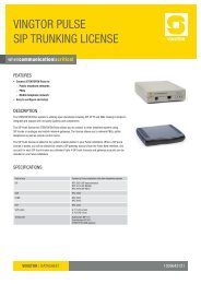
J. CONTROL ROOM MASTER (CRM-IV). Compact desk top console master shall include a 3" speaker,<br />
condenser microphone with preamplifier and automatic sensitivity adjustment, handset with coiled<br />
cord, dial keypad with manual and cancel button, privacy switch, optional programmable direct<br />
access buttons (modules of 48 buttons, with a maximum of two modules), (4) function buttons and a 4<br />
line 20 character alphanumeric, backlit LCD display. Shall allow up to (100) call requests in queue<br />
with (256) priority levels, and allow multiple parallel masters with transfer of command. Shall operate<br />
with only (3) pair twisted #22 gauge wire. Shall be Stentofon #7006102.<br />
7006102<br />
K. CONTROL ROOM MASTER. This advanced control room master features a large 4 x 20 character<br />
alphanumeric LCD display with backlight. This station shall have a full dialing keypad, 10<br />
programmable single touch keys, answer-next-in-queue key, handset, sensitive electret microphone<br />
and a powerful 1W loudspeaker. The station shall have full loudspeaking conversation with automatic<br />
switching of the speech direction. This station shall be able to manually override the automatic<br />
speech switching for a push-to-talk operation. Handset is optional order part # 92497 (Desk) #92495<br />
(Rack). Temperature Range: 0° C +40° C (+32° F to +104° F); Dimensions: 14” x 7” x 3” (Desk) 5 ¼”<br />
x 19” (Rack); Finish: Black; Loudspeaker Output: 1 W (63 Ohm) Frequency Range: 300-5,000 Hz.<br />
Shall operate with only (3) pair twisted #22 gauge wire. Shall be the Stentofon #7053R (Rack) or<br />
#7053D (Desk).<br />
7053 Rack Mount 7053 Desk Mount<br />
STENTOFON/<strong>Zenitel</strong> Group - 6119 Connecticut Ave. – Kansas City, MO 64120 – 816/231-7200 – 800/654-3140 – Fax: 816/231-7203 – www.zenitelusa.com<br />
- 14 -
Revised May 2009<br />
L. STAINLESS STEEL SUBSTATION (OUTDOOR/INDOOR). Shall be a tamper resistant, electronic<br />
substation with one (1) stainless steel call request push button, a 2.5", 45 ohm speaker, an electret<br />
condenser microphone with preamplifier mounted on a 11 gauge, #304 Stainless Steel face plate.<br />
The call button shall be programmed to call a specific master. The electronic board shall be encased<br />
in epoxy and have built in transient suppression and plate shall include a rubberized gasket. Shall<br />
mount on a standard (2) gang deep electrical back box, box provided by others. 6291 series isn’t<br />
recommend for outdoor installations, but if installed outside installer must drill weep holes in backbox.<br />
Shall be Stentofon #6291 or #6291RM (Optional Red Call Button).<br />
6291 (6291RM - with red mushroom button)<br />
M. STAINLESS STEEL SUBSTATION (OUTDOOR/INDOOR). Shall be a tamper resistant, electronic<br />
substation with one (1) or two (2) stainless steel call request push button(2), a 2.5", 45 ohm speaker,<br />
an electret condenser microphone with preamplifier mounted on a 11 gauge, #304 Stainless Steel<br />
face plate. The call button shall be programmed to call a specific master. The electronic board shall<br />
be encased in epoxy and have built in transient suppression and plate shall include a rubberized<br />
gasket. Shall mount on a standard (3) gang deep electrical back box, box provided by others. 6294<br />
series isn’t recommend for outdoor installations, but if installed outside installer must drill weep holes<br />
in backbox. Shall be Stentofon #6294-1 or #6294-2. Optional #6294RM (Optional Red Call Button,<br />
not shown).<br />
6294 (6294-2 with two button option)<br />
N. EXTERIOR TAMPER-RESISTANT SUBSTATION. This station shall be tamper resistant with one<br />
1.5” red mushroom button. The station shall be mounted on a 1/4" thick aluminum plate designed to<br />
withstand extreme abuse. Moisture resistant speaker and microphone shall be mounted behind two<br />
offset grills, milled into aluminum block to prevent damage from foreign material or water. The<br />
electronic board shall be encased in epoxy and have built in transient suppression and plate shall<br />
include a rubberized gasket. The station shall mount on a #6297 flush, #6298 surface or #62991 cast<br />
weatherproof backbox. If installed outside installer must drill weep holes in backbox. Shall be<br />
Stentofon #62927. Also available in dual button version #62922-7 where top button is silver and<br />
bottom button is red.<br />
62927<br />
STENTOFON/<strong>Zenitel</strong> Group - 6119 Connecticut Ave. – Kansas City, MO 64120 – 816/231-7200 – 800/654-3140 – Fax: 816/231-7203 – www.zenitelusa.com<br />
- 15 -
Revised May 2009<br />
O. HANDSET SUBSTATION. This station shall be a durable master station with handset designed to<br />
automatically place a call when the handset is picked up. By software programming you shall have<br />
the ability to either have a 10 button substation or unit will call a single location by lifting the handset<br />
off hook. This station shall include a red call placed LED. This station shall mount on #6020 flush or<br />
#6031 surface backbox as required.; Faceplate: 1/8” (.125) aluminum finished in ultrasonic grey<br />
paint; Size: 11” H x 4.9” W x 4” D (280 x 125 x 102 mm); Shall be Stentofon #7045US.<br />
7045US<br />
P. ELEVATOR SUBSTATION. The station shall be functional equivalent of a #6294 series substation,<br />
without faceplate. It shall be designed to mount behind appropriate panel provided by elevator<br />
company. Kit, model 1063 shall consist of an electronic preamplifier board, with necessary screw<br />
terminals, a 4" 45 ohm speaker and condenser microphone. Finish shall be black epoxy. When<br />
mounted on a sub plate shall be Stentofon model #1064. Call-in button shall be provided by elevator<br />
company.<br />
1064<br />
Q. SECURITY/EMERGENCY SUBSTATION. This station shall have an 11 gauge stainless steel<br />
faceplate with a 3" weather resistant speaker, protected electret microphone, high intensity 1/2" LED<br />
and a large red mushroom call button. Substation shall operate from -10°F to +120°F. Shall include<br />
circuitry for a strobe control board. Shall mount on a 1041 (Stainless Steel Back box as shown<br />
below), 1042 (Rolled Steel Back box-Yellow) or standard stanchions and wall units provided by<br />
Stentofon. If installed outside installer must drill weep holes in backbox. Shall be Stentofon #62927-9.<br />
62927-9 in backbox<br />
STENTOFON/<strong>Zenitel</strong> Group - 6119 Connecticut Ave. – Kansas City, MO 64120 – 816/231-7200 – 800/654-3140 – Fax: 816/231-7203 – www.zenitelusa.com<br />
- 16 -
Revised May 2009<br />
R. IP DESK MASTER STATION. Desk master station for use in offices and control rooms. Station<br />
features a large high contrast display with backlight which allows important information about<br />
connections to be shown. The 80010 is equipped with 10 DAK keys that provide single touch access<br />
to stations, group calls, etc and handset for confidential conversations. It connects directly to IP<br />
network making it easy to deploy anywhere at any distance, and has an integrated web server for<br />
easy configuration, monitoring and remote automatic software updates. Station provides wideband<br />
audio. Connection must be to a PoE switch. Shall be Stentofon # 80010 IP Desk Master w/handset or<br />
#80000 IP Desk Master.<br />
80010 80000<br />
S. IP OR MASTER. Master station for use in operating and clean rooms that require chemical resistant<br />
and anti-bacterial front surface for easy cleaning. Station features a large high contrast display with<br />
backlight and up to 8 lines with 20 characters as well as the added feature of lighting behind each key<br />
that provides excellent readability in locations where lighting can be a problem. Station connects<br />
directly to IP network making it easy to deploy anywhere at any distance. Station has integrated web<br />
server for easy configuration, monitoring and remote a automatic software updates are built in<br />
features. Station provides wideband audio and may be powered locally or connected to a POE<br />
switch. Station can be mounted in flush 80987 backbox. Optional handset unit 80971 is available as<br />
an option. Shall be Stentofon 80150 IP OR Master.<br />
80150<br />
STENTOFON/<strong>Zenitel</strong> Group - 6119 Connecticut Ave. – Kansas City, MO 64120 – 816/231-7200 – 800/654-3140 – Fax: 816/231-7203 – www.zenitelusa.com<br />
- 17 -
Revised May 2009<br />
T. IP FLUSH MASTER. Flush master station with display is a general purpose intercom station Intended<br />
for use where a desktop station is impractical. Station features a large high contrast display with<br />
backlight which allows important information about connections to be shown very clearly. Station is<br />
equipped with 4 DAK keys that provide single-touch access to stations and features. Station connects<br />
directly to IP network making it easy to deploy anywhere at any distance. Station has integrated web<br />
server for easy configuration, monitoring and remote automatic software updates are built in features.<br />
Station provides wideband audio and may be powered locally or connected to a POE switch. Station<br />
can be mounted in flush 80987 backbox. Optional handset unit 80971 is available as well as optional<br />
gooseneck microphone 80975. Shall be Stentofon 80310 IP FLUSH MASTER<br />
80310<br />
U. IP INDOOR TAMPER RESISTANT SUBSTATION. Shall be a tamper resistant, electronic substation<br />
with one (1) stainless steel call request push button, a 2.5", 45 ohm speaker, an electret condenser<br />
microphone with IP substation board on a 11 gauge, #304 Stainless Steel face plate. The call button<br />
shall be programmed to call a specific master or feature. The IP substation shall be equipped with<br />
dual IP ports for possible daisy chaining of IP stations or devices, integrated web server for<br />
programming, wideband audio (7kHz), dry relay contact for door opening or strobe control and line<br />
monitoring as standard features and mounting plate shall include a rubberized gasket. Shall mount on<br />
a standard (3) gang deep electrical back box, box provided by others. IP6294-1 isn’t recommended<br />
for outdoor installations, but if installed outside installer must drill weep holes in backbox. Shall be<br />
Stentofon #IP6294-1. Optional #IP6294RM (Optional Red Call Button), not shown.<br />
IP6294-1<br />
STENTOFON/<strong>Zenitel</strong> Group - 6119 Connecticut Ave. – Kansas City, MO 64120 – 816/231-7200 – 800/654-3140 – Fax: 816/231-7203 – www.zenitelusa.com<br />
- 18 -
Revised May 2009<br />
V. IP EXERIOR TAMPER RESISTANT SUBSTATION. This station shall be tamper resistant with one<br />
1.5” red mushroom button. The station shall be mounted on a 1/4" thick aluminum plate designed to<br />
withstand extreme abuse. Moisture resistant speaker and microphone shall be mounted behind two<br />
offset grills, milled into aluminum block to prevent damage from foreign material or water. The IP<br />
substation shall be equipped with dual IP ports for possible daisy chaining of IP stations or devices,<br />
integrated web server for programming, wideband audio (7kHz), dry relay contact for door opening or<br />
strobe control and line monitoring as standard features. The station shall mount on a #6297 flush,<br />
#6298 surface or #62991 weatherproof backbox. If installed outside installer must drill weep holes in<br />
backbox. Shall be Stentofon #IP62927.<br />
IP62927<br />
W. IP SECURITY/EMERGENCY SUBSTATION. This station shall have an 11 gauge stainless steel<br />
faceplate with a 3" weather resistant speaker, protected electret microphone, high intensity 1/2" LED<br />
and a large red mushroom call button. Substation shall operate from -10°F to +120°F. The IP<br />
substation shall be equipped with dual IP ports for possible daisy chaining of IP stations or devices,<br />
integrated web server for programming, wideband audio (7kHz), dry relay contact for door opening or<br />
strobe control and line monitoring as standard features. Shall mount on a 1041 (Stainless Steel Back<br />
box as shown below), 1042 (Rolled Steel Back box-Yellow) or 1600 series stanchions and wall units<br />
provided by Stentofon. If installed outside installer must drill weep holes in backbox. Shall be<br />
Stentofon #IP62927-9.<br />
IP62927-9 in backbox<br />
STENTOFON/<strong>Zenitel</strong> Group - 6119 Connecticut Ave. – Kansas City, MO 64120 – 816/231-7200 – 800/654-3140 – Fax: 816/231-7203 – www.zenitelusa.com<br />
- 19 -
Revised May 2009<br />
X. IP VANDAL RESISTANT IP SUBSTATION. This station shall have a 2mm stainless steel faceplate<br />
and shall be equipped with dual IP ports for possible daisy chaining of IP stations or devices,<br />
integrated web server for programming, wideband audio (7kHz), dry relay contact for door opening or<br />
strobe control and line monitoring as standard features. Station shall be equipped with a one call<br />
button. Shall flush mount in 80981 backbox or surface mount in 80980 backbox. Shall be Stentofon<br />
#IP80411<br />
IP80411<br />
Y. IP VANDAL RESISTANT IP SUBSTATION. This station shall be have a 2mm stainless steel Faceplate<br />
and shall be equipped with dual IP ports for possible daisy chaining of IP stations or devices, integrated<br />
web server for programming, wideband audio (7kHz), dry relay contact for door opening or strobe<br />
control and line monitoring as standard features. Station shall be equipped with a red raised red call<br />
button. Station shown be mounted vertically in 3-gang electrical flush or surface mount back box for<br />
proper installation. 3-gang electrical back box to be provided by others. Shall be Stentofon #IP80510<br />
IP80510<br />
Z. IP PAGE ADAPTER. This page adapter shall be IP based and have much the same features as IP<br />
substations such as dual IP ports, integrated web server for programming, dry relay contact for<br />
possible muting of music on PA amplifier along with line monitoring. Output shall be balanced 600<br />
ohm, 0Db for connection to PA amplifer and speakers to allow for paging of internal or external areas<br />
over IP to local or remote sites as required. IP Page Adapter shall be enclosed in a box to allow for<br />
easy mounting. Shall be Stentofon #IP1078 Page Adapter<br />
STENTOFON/<strong>Zenitel</strong> Group - 6119 Connecticut Ave. – Kansas City, MO 64120 – 816/231-7200 – 800/654-3140 – Fax: 816/231-7203 – www.zenitelusa.com<br />
- 20 -
Revised May 2009<br />
AA. CAMPUS EMERGENCY SIGNALLING UNIT. Unit shall include a 50 watt constantly glowing blue<br />
identification luminaries, a small 7 watt fluorescent to illuminate the substation and an extremely<br />
bright 1.5 million candle power blue flash strobe. Lamps shall have blue prismatic Lexan lenses with<br />
clear UV protected polycarbonate outer lenses. Unit shall be a 10 gauge stainless steel wall or pole<br />
mount weather proof housing that is 42" high by 12" wide with silk screened "emergency" signs. Shall<br />
be Stentofon #1600 series units. Order unit Security/Emergency Substation 62927-9 or IP62927-9.<br />
1600 1601 1602 1603<br />
BB. CENTRAL EXCHANGE. The central exchange shall provide all control, logic, signaling, “duplex”<br />
switching amplification, power and all operating features listed throughout this specification. All<br />
circuitry and components shall be arranged on slide-in printed circuit boards that are 100 percent<br />
solid-state, employing latest “state-of-the-art” design. Crossbar, relay, or electro-mechanical switching<br />
of any type, will not be acceptable.<br />
Expansion to ultimate cabinet capacity shall require only the addition of "Hot Plug in/out" type<br />
subscriber boards for analog wired stations or IP stations with the necessary software licenses.<br />
Station capacity of the exchange shall be increased by (6) and speech paths by ( 1 ), each time a<br />
single subscriber board for analog wired stations is inserted. All subscriber boards shall be identical<br />
and interchangeable. Malfunction of one subscriber board shall not affect more than six stations.<br />
Malfunction of one wire to a subscriber board shall not affect more than one station. Basic exchange<br />
shall have capacity for (23) subscriber boards, expandable to (92) boards. No additional hardware<br />
boards or proprietary black boxes will be necessary to do the networking via IP between <strong>AlphaCom</strong> E<br />
exchanges to create a single system of up to 254 nodes with a total stations capacity including wired<br />
analog stations and IP stations to the maximum of 140,208 stations in total.<br />
The exchange shall support the mix of IP and traditional stations as desired. The exchange shall<br />
support SIP protocol to allow for interfacing to VoIP telephones and or systems and equipment. The<br />
system shall provide special features such as the capability of redundancy via IP, wideband audio<br />
(7kHz), built in firewall, integrated web & SIP server as well as low latency switching. The exchange<br />
shall allow for remote programming, logging and maintenance via IP using AlphaPro as well as<br />
additional maintenance and statistical information via IP using web browser to interface to AlphaWeb.<br />
STENTOFON/<strong>Zenitel</strong> Group - 6119 Connecticut Ave. – Kansas City, MO 64120 – 816/231-7200 – 800/654-3140 – Fax: 816/231-7203 – www.zenitelusa.com<br />
- 21 -
Revised May 2009<br />
Exchange shall provide (_6_) Remote Control Outputs Signals (RCO's) per subscriber board.<br />
Exchange shall have capacity for simultaneous conversations equal to the number of speech<br />
channels installed. There shall be (1) speech channel for every (6) subscribers. System shall assign<br />
speech channels in absolute rotation, and all stations shall have access to all speech channels.<br />
Malfunction of one speech channel shall not affect operation of the system. Every speech channel<br />
shall include “compression” circuits to automatically control and limit sound volume during<br />
conversation. Compression circuits shall limit audio distortion and clipping.<br />
The intercom exchange shall include a custom-made software program, stored in FLASH memory,<br />
specifically designed for the system. Programming software (AlphaPro) shall operate on a PC with<br />
Windows, and include a menu for standard features and directory numbers, which may be entered by<br />
one operation. AlphaPro software shall provide unlimited flexible numbering and programmable<br />
features. Microprocessor shall include (2) Ethernet IP ports and 2 serial data ports to allow direct<br />
transfer of call processing information, to and from other microprocessor controlled equipment.<br />
It shall be possible to reprogram the exchange, at the exchange location or remotely through IP, and<br />
the programming shall take effect immediately. All programmable information shall be protected<br />
against power failure and reset, and maintained in flash memory. Flash memory shall be located on<br />
the processor board. It shall be possible to export via AlphaPro the user information as well as<br />
AlphaNet audio and data links and open using Microsoft Office Excel. Load sharing, closely regulated<br />
power supplies shall power exchange. System shall easily allow for redundancy by adding a power<br />
supply to the exchange.<br />
Exchange shall comply with EMC standards EN55022 for electromagnetic emissions, and EN50082<br />
for immunity. System shall include self-diagnostic circuitry and alarms for electronic supervision of<br />
boards and wiring.<br />
Audio power output to each station shall be adjustable from 1-1.5 watts of audio at an impedance of<br />
20 ohms. Frequency response for both input and output shall be a smooth curve through the voice<br />
range of 200 - 10,000 Hz on intercom, and 200 - 15,000 Hz on audio program channel. Crosstalk<br />
shall be less than -80 dB @ 1000 Hz, and S/N ratio shall be >80 dB during conversation. Loop<br />
resistance requirements for each station shall be 240 ohms. Traffic capacity shall allow each user<br />
99% chance of connection, at 0.05 Erlang traffic, at all cabinet capacities. If temporarily blocked,<br />
system shall allow automatic and immediate connection when free. Central exchange shall include<br />
all necessary boards, hardware, software, and accessories to support features and functions<br />
described herein. Shall be Stentofon <strong>AlphaCom</strong> Evolution Series.<br />
<strong>AlphaCom</strong> E26<br />
<strong>AlphaCom</strong> E7<br />
(Note to specifier: Indicate exact model number of central exchange)<br />
STENTOFON/<strong>Zenitel</strong> Group - 6119 Connecticut Ave. – Kansas City, MO 64120 – 816/231-7200 – 800/654-3140 – Fax: 816/231-7203 – www.zenitelusa.com<br />
- 22 -
Revised May 2009<br />
2.7. OPTIONS (Available with additional equipment)<br />
(Note to specifier: Indicate options required)<br />
A. SIP GATEWAY TELEPHONE INTERFACE. System shall include an interface to allow telephone calls<br />
to be directed in, and out, of the system for two-way communication between intercom stations and<br />
remote telephones via IP using SIP protocol. Selected master stations shall be able to dial an access<br />
code [0], receive PABX or Central Office dial tone, and dial any unrestricted telephone number and<br />
vice versa. Requires SIP trunking license 9642-xxx and license is dependent on how many telephone<br />
lines used. Shall be Stentofon MP-114 SIP Gateway.<br />
B. DYNAMIC MICROPHONE PREAMPLIFIER BOARD. Shall provide calling and two-way<br />
communication through same loudspeaker. Shall include relay control and adjustments for in/out<br />
volume. Shall be Stentofon #1078.<br />
C. STROBE CONTROL RELAY BOARD. Shall be mounted in security substations that have an<br />
associated strobe light. Shall provide necessary contacts to turn on flashing strobe when intercom call<br />
button is depressed and program to place a call request call and when the call is answered. Strobe<br />
shall turn off when intercom conversation is canceled. Shall be Stentofon #9689-2.<br />
D. REMOTE IN/OUT CONTROL (RIO). Electronic board shall be included where ancillary devices need<br />
to be operated through relay contacts from the intercom system (outputs), and/or external alarm<br />
conditions need to be displayed as text or voice message on LCD intercom masters. Devices like<br />
bells, lights, CCTV cameras, electric door releases and amplifiers and other devices may be turned<br />
“on” or “off” by actions created by programming. Unit shall be equipped with 8 contact inputs<br />
(Standard) and up to 18 contact outputs (When equipped with optional 99702 Relay Board (6<br />
contacts per board). It shall be possible to have multiple outputs per station. Shall be Stentofon<br />
#99705.<br />
E. STORED VOICE MESSAGES. System shall allow digitally stored voice messages to be automatically<br />
transmitted to selected stations, or all stations. Shall be microprocessor controlled to store up to 60<br />
minutes of speech messages, and allow simultaneous play back of up to 8 messages. Shall include<br />
(9) pre-recorded voice help, (9) absence and (3) alarm messages standard to selected stations. Shall<br />
provide call request verification to initiator of the call. The prerecorded voice messages shall be<br />
natural sounding, high quality with 16 kHz sampling rate. A Call Acknowledge message to elevator<br />
car substations shall meet A.D.A requirements. Customized alarm messages shall be available from<br />
the manufacturer. Message board shall be Stentofon #9304 AVSP.<br />
F. PAGE ADAPTOR. System shall include an interface to allow the Stentofon <strong>AlphaCom</strong> intercom<br />
system to be connected to an overhead paging system. Adapter shall include a relay to control or<br />
mute music in an amplifier and shall have a transformer-isolated output of 600 ohms, up to 1 volt. The<br />
adapter shall be accessed by dialing the station number assigned to the page adapter or pressing a<br />
direct access button. The page adaptor is required for each zone or page amplifier to be accessed.<br />
Shall be housed in a black, ABS plastic box with mounting flange and cover. Shall be Stentofon<br />
#1078. Optional Mounting via #63212 card cage.<br />
STENTOFON/<strong>Zenitel</strong> Group - 6119 Connecticut Ave. – Kansas City, MO 64120 – 816/231-7200 – 800/654-3140 – Fax: 816/231-7203 – www.zenitelusa.com<br />
- 23 -
Revised May 2009<br />
G. AUTOMATIC SOUND DETECTION ALARM BOARD. The system shall include the necessary<br />
number of sound detection relay boards to monitor the audio level in areas such as elevators,<br />
selected stairwells and some areas of the parking garage. Each intercom substation that is monitored<br />
shall be connected to an individual detection board. Each board shall include (6) controls for manual<br />
adjustments of ambient conditions in each area. Each board shall also allow automatic compensation<br />
for changes to ambient conditions over a specific time period. Dynamic range shall be over 40 dB,<br />
with timing adjustments from 1 - 33 seconds. BOARD. Shall be Stentofon #SDR-115 mounted in<br />
card cage series. SDR-DR XX – XX equals number of board positions to multiples of 5 up to 25 slots<br />
per card cage.<br />
(Note to specifier: indicate which stations require sound detection)<br />
H. VOICE RECORDER BOARD. System shall include a (6) circuit electronic buffer board with 600 ohm<br />
output to match audio recording machines. Shall provide interface to record conversations of six<br />
different pairs of intercom stations. Shall be housed in box with cover. Shall be Stentofon #1082C<br />
VRB Unit<br />
I. ATLB TELEPHONE LINE BOARD. This board shall provide the ability to connect standard DTMF<br />
telephones to <strong>AlphaCom</strong> to act as stations. The board provides 12 telephone connections and 1<br />
voice-switched speech channel. The board also provides 6 remote control outputs signals (RCO’s).<br />
Each telephone connects to ATLB board with standard 2-wire connection. Any station connected to<br />
the telephone board can be included in an open duplex conference. Shall be Stentofon #9104.<br />
J. FIBER COUPLER MODULES. These boards shall allow any 4-wire intercom station, master or<br />
substation to be connected to <strong>AlphaCom</strong> exchange using 2 multi-mode fibers per station. These<br />
modules shall maintain system and station supervision. The fiber modules will support LCD and non-<br />
LCD master stations along with substations. Fiber modules shall be wall or rack mounted. Shall be<br />
STENTOFON #92860M (Exchange Module) and #92860F (Field Module). LCD stations require fiber<br />
couplers #92860MD (Exchange Module) and #92860FD (Field Module).<br />
K. REMOTE CONTROL RELAY BOARD. This board shall provide 6 dry relay contacts which shall be<br />
programmable from AlphaPro software and triggered by events such as door/gate openings, CCTV<br />
control and strobe control. Shall be Stentofon #99702<br />
2.8. ALPHACOM SOFTWARE LICENSES<br />
A. ALPHACOM ALPHANET & MULTI-MODULE VOIP LICENSE. This software license makes it<br />
possible to establish audio communication between <strong>AlphaCom</strong> E exchanges that are connected in an<br />
IP configuration. Each <strong>AlphaCom</strong> E exchange will require a software license. Software license shall<br />
be part number 9640-xxx where xxx is determined depending on the design scope of the system on a<br />
node by node basis.<br />
(Note to specifier: Indicate if 9640-xxx license(s) are required)<br />
B. ALPHACOM IP STATION LICENSE. This software license makes it possible to connect and register<br />
IP stations (masters & substations) via IP to an <strong>AlphaCom</strong> E exchange. Once IP station is registered<br />
it can then place intercom calls just like traditional copper wired stations. Depending on the number<br />
of IP station(s) that are required for the job then multiples of IP station license 9641-006 will be<br />
required. Software license shall be part number 9641-006 which is good for registering 6 IP stations.<br />
(Note to specifier: Indicate if 9641-006 license(s) are required)<br />
STENTOFON/<strong>Zenitel</strong> Group - 6119 Connecticut Ave. – Kansas City, MO 64120 – 816/231-7200 – 800/654-3140 – Fax: 816/231-7203 – www.zenitelusa.com<br />
- 24 -
Revised May 2009<br />
C. ALPHACOM SIP TRUNKING LICENSE. This software license makes it possible to connect<br />
<strong>AlphaCom</strong> E to VOIP IP Phone systems or traditional PBX that aren’t IP capable if combined and<br />
used with a MP-114 or MP-118 SIP Gateway. SIP trunking gives a seamless integration between the<br />
<strong>AlphaCom</strong> E and other telecom systems supporting SIP which allows for advanced functions.<br />
Software license shall be part number 9642-xxx where is xxx is determined depending on the design<br />
scope of the system.<br />
(Note to specifier: Indicate if 9642-xxx license(s) are required)<br />
D. ALPHACOM SIP STATION LICENSE. This software license makes it possible to connect and register<br />
SIP based phones via IP with the <strong>AlphaCom</strong> E system. Once the SIP based phone is registered it<br />
can then place and receive intercom calls must like a traditional intercom station. Depending on the<br />
number of SIP phones that are required for the job then multiples of the 9643-006 will be required.<br />
Software license shall be 9643-006 which will allow 6 SIP phones to register.<br />
(Note to specifier: Indicate if 9643-006 license(s) are required)<br />
E. ALPHACOM OPC LICENSE. This software license makes it possible to connect and register details<br />
regarding events occurring in the <strong>AlphaCom</strong> E intercom system to external OPC based management<br />
system. Using this software license greatly reduces the need to write specific interface protocol as<br />
OPC is an industry standard based on OPC and Microsoft .Net. Software license shall be 964990X<br />
where x is determined by how many stations you wish to monitor.<br />
STENTOFON/<strong>Zenitel</strong> Group - 6119 Connecticut Ave. – Kansas City, MO 64120 – 816/231-7200 – 800/654-3140 – Fax: 816/231-7203 – www.zenitelusa.com<br />
- 25 -
Revised May 2009<br />
PART III: EXECUTION<br />
3.1. INSTALLATION<br />
A. Shall be installed by qualified technicians who have been factory trained and certified.<br />
B. Wiring shall be uniform and in accordance with national electric codes and manufacturers’<br />
instructions.<br />
C. Equipment shall be firmly secured, plumb, and level.<br />
D. All splices shall be in easily accessible junction boxes or on terminal boards.<br />
E. All cable runs at the main terminal board and in all junction boxes shall be tagged and identified.<br />
F. Coordinate all work with other effected trades and contractors.<br />
3.2. SYSTEM INITIALIZING AND PROGRAMMING<br />
A. System shall include all software necessary for system configuration.<br />
B. System shall be turned on and adjustments made to meet requirements of specifications and on-site<br />
conditions.<br />
C. System shall be programmed to function as specified.<br />
D. Directory numbers, feature codes, and special programming shall be documented, printed and made<br />
available to owner.<br />
3.3. SYSTEM TEST PROCEDURES<br />
A. System shall be completely tested to assure that the exchange and all components, stations,<br />
speakers, and accessories are hooked-up and in working order.<br />
B. System shall be pre-tested by contractor and certified to function in accordance with plans and<br />
specifications.<br />
C. System shall be tested in presence of owner's representative.<br />
3.4. OWNER INSTRUCTIONS<br />
A. Installation contractor shall conduct up to (4) hours of instruction in use and operation of the system<br />
to designated owner representatives, within (30) days of system acceptance. Owner will print and<br />
distribute directory number plan to users.<br />
B. Installation contractor shall conduct up to (4) hours of technical training, in programming,<br />
troubleshooting, and service of the system, to designated owner representatives within (90) days of<br />
system acceptance.<br />
C. Manufacturer shall conduct periodic technical training seminars and make them available to those<br />
responsible for on-going maintenance of the system.<br />
STENTOFON/<strong>Zenitel</strong> Group - 6119 Connecticut Ave. – Kansas City, MO 64120 – 816/231-7200 – 800/654-3140 – Fax: 816/231-7203 – www.zenitelusa.com<br />
- 26 -
Revised May 2009<br />
3.5. ON-SITE SPARES<br />
A. The following items shall be included in the system package and turned over to owner within (30)<br />
days of system acceptance.<br />
1. (1) Central exchange spare parts kit.<br />
2. (1) Desk master Station.<br />
3. (1) Tamper resistant security substation.<br />
4. (1) Wall master station.<br />
3.6. MANUALS AND DRAWINGS<br />
(Note to specifier: Indicate exact items required)<br />
A. Contractor shall provide owner with (2) copies of standard factory prepared operation, installation and<br />
maintenance manuals. Manuals shall include typical wiring diagrams.<br />
B. Contractor shall provide owner with (2) copies of any risers, layouts, and special wiring diagrams<br />
showing any changes to standard drawings, if required on project.<br />
STENTOFON/<strong>Zenitel</strong> Group - 6119 Connecticut Ave. – Kansas City, MO 64120 – 816/231-7200 – 800/654-3140 – Fax: 816/231-7203 – www.zenitelusa.com<br />
- 27 -