Reporter No. 62, April 2010, English (PDF 2.17 MB) - Leica ...
Reporter No. 62, April 2010, English (PDF 2.17 MB) - Leica ...
Reporter No. 62, April 2010, English (PDF 2.17 MB) - Leica ...

Create successful ePaper yourself
Turn your PDF publications into a flip-book with our unique Google optimized e-Paper software.
<strong>62</strong><br />
The Global Magazine of <strong>Leica</strong> Geosystems
Editorial<br />
Dear Readers,<br />
Changes – be them of social, political, economic or<br />
even personal nature – are an integral part of our life.<br />
<strong>Leica</strong> Geosystems has undergone many changes during<br />
its 200 years of existence. This was partly due to<br />
economic reasons – our environment changed, and<br />
so did we. But of the same importance, fundamental<br />
changes to our company have been fueled through<br />
new technologies. These have enabled us to evolve<br />
and develop innovations and new systems that have<br />
not only shaped our company but have influenced<br />
the whole industry.<br />
CONTENTS<br />
03<br />
06<br />
08<br />
10<br />
12<br />
14<br />
16<br />
19<br />
20<br />
Track Monitoring in Real-Time<br />
via the Web<br />
Straight Up to the Sky<br />
Reclaiming Efficency<br />
3D Laser Scanning<br />
Reduces Risks<br />
Precision Concrete<br />
for 300 km/h Trains<br />
Searching for<br />
Bombs Under Water<br />
Gateway to Korea<br />
Adventure Surveying<br />
on Mont Blanc<br />
Accurate, Enriched<br />
Data at Lower Cost<br />
Changes are an important part of the evolutionary<br />
cycle and influence every part of our daily lives.<br />
But change is only successful if one remains true to<br />
23<br />
The <strong>Leica</strong> Lino Family:<br />
Everything Level<br />
themselves. <strong>Leica</strong> Geosystems did so, even as the<br />
company has continued to innovate, enlarge its customer<br />
base, and establish itself in many new mar-<br />
23<br />
2009 <strong>Leica</strong> Geosystems HDS<br />
Worldwide User Conference<br />
kets – e.g., offering solutions for the construction<br />
industry, for machine control and for laser scanning.<br />
On occasion of Bauma, the construction machinery<br />
exhibition in Munich, in this edition of the “<strong>Reporter</strong>”<br />
we have laid a strong focus on the construction and<br />
engineering business, although we have tried to<br />
give you an impression on the broadness of <strong>Leica</strong><br />
Geosystems’ applications spectrum.<br />
Changes held <strong>Leica</strong> Geosystems also for me personally.<br />
When I joined the company 15 years ago as a<br />
surveying engineer, I wouldn’t have thought that I<br />
could say ‘Enjoy reading the new <strong>Reporter</strong>!’ to you as<br />
the new CEO. Thus, in the name of <strong>Leica</strong> Geosystems,<br />
I am pleased to invite you to visit our booth at Bauma<br />
(Hall A3, Booth 141/232) from 19 to 25 <strong>April</strong>!<br />
Juergen Dold<br />
CEO <strong>Leica</strong> Geosystems<br />
Imprint<br />
<strong>Reporter</strong>: Customer Magazine of <strong>Leica</strong> Geosystems<br />
Published by: <strong>Leica</strong> Geosystems AG, CH-9435 Heerbrugg<br />
Editorial Office: <strong>Leica</strong> Geosystems AG,<br />
9435 Heerbrugg, Switzerland, Phone +41 71 727 34 08,<br />
reporter@leica-geosystems.com<br />
Contents responsible: Alessandra Doëll<br />
(Director Communications)<br />
Editor: Agnes Zeiner, Konrad Saal<br />
Publication details: The <strong>Reporter</strong> is published in <strong>English</strong>,<br />
German, French, and Spanish, twice a year.<br />
Reprints and translations, including excerpts, are subject to<br />
the editor’s prior permission in writing.<br />
© <strong>Leica</strong> Geosystems AG, Heerbrugg (Switzerland),<br />
March <strong>2010</strong>. Printed in Switzerland<br />
2 | <strong>Reporter</strong>
Track Monitoring<br />
in Real-Time via<br />
the Web<br />
by Markus Prechtl<br />
To reduce traffic through town, the local authority<br />
for the German town of Traunstein decided<br />
to build a bypass road starting in spring 2009<br />
and including a new tunnel under the Munich –<br />
Salzburg railway line. The track owner, Deutsche<br />
Bahn AG (DB), stipulated continuous monitoring<br />
of the stretch of rail affected by the tunneling<br />
operations. Lead consultant Bernd Gebauer<br />
GmbH decided to install a track position monitoring<br />
system and engaged consulting engineers<br />
ing Traunreut GmbH for the task. The system of<br />
freely combinable measurement sensors from<br />
<strong>Leica</strong> Geosystems in conjunction with the <strong>Leica</strong><br />
GeoMoS or GeoMoS Web monitoring software<br />
proved to be perfectly suited to this task.<br />
The strict conditions imposed by DB required the<br />
monitoring system to meet very high demands. The<br />
installed tilt sensors had to ensure a measuring accuracy<br />
of ± 0.3 mm/m, while an accuracy of ± 1.0 mm<br />
was required for total station measurements. Reliability<br />
of the system is very important, particularly<br />
with regard to storage and security of the measured<br />
data. One of the precautions taken by ing Traunreut<br />
was therefore to install a fallback system for<br />
data transfer via UMTS, in addition to the fixed data<br />
>><br />
The Global Magazine of <strong>Leica</strong> Geosystems | 3
lines (DSL), to safeguard data transfer in the event of<br />
a failure. Another requirement was that the measuring<br />
system must have an independent power supply<br />
capable of bridging short-term outages. If the specified<br />
tolerances are exceeded, the system alerts the<br />
DB track manager by text message. In addition, there<br />
is also an optional notification by land-line.<br />
Data Retrieval with <strong>Leica</strong> GeoMoS Web<br />
The engineers are able to display and analyze the captured<br />
monitoring data over the Internet using Geo-<br />
MoS Web. The GeoMoS Monitor module uploads measured<br />
data to the GeoMoS Web server via FTP. There<br />
the data can be individually configured and displayed<br />
graphically. Users with appropriate access codes can<br />
then access the information via web. The use of the<br />
<strong>Leica</strong> Geosystems host service (“Software as a Service”)<br />
minimizes or even eliminates costs for hardware,<br />
software, and IT. New features are always made<br />
immediately available to all users and do not require<br />
any further installation on the customer's computer,<br />
while the encrypted web service looks after the secure<br />
transfer of data over the Internet. The customer gains<br />
access to the graphics on GeoMoS Web from a login<br />
screen. Once logged in, he can analyze the data, e.g.<br />
by changing the time frame or extracting the results<br />
from one or more points or sensors. By installing a<br />
high-resolution webcam ing Traunreut offers customers<br />
the additional benefit of a quick overview of the<br />
actual site conditions through GeoMoS Web.<br />
Changes in Track Position<br />
With GeoMoS Web, the client can get information<br />
about current changes in track position at any time<br />
during the works. Some of the larger movements<br />
were observed in particular during tunnel shield driving<br />
in Phase 2. On two occasions it was necessary to<br />
carry out track rectification after a depression with a<br />
vertical displacement of up to 25 mm appeared in a<br />
length of track. Since the start of track monitoring,<br />
the track has settled up to 5 cm. However, not just<br />
tracks are affected: movements were also observed<br />
in the overhead line masts. A tilt of almost 7 mm/m<br />
developed in a mast foundation, which translated into<br />
a displacement of the overhead line of 3 to 4 cm and<br />
meant that the position of the overhead line on the<br />
southern mast had to be corrected. All settlements<br />
were detected at an early stage by the monitoring<br />
system. This allowed appropriate early corrective<br />
measures to be implemented before reaching a stage<br />
where notification of the track maintenance manager<br />
would have been necessary – which would have triggered<br />
an expensive temporary closure of that complete<br />
section. Instead, corrective work could be carried<br />
out between trains or required only a temporary<br />
closure of the track in one direction.<br />
4 | <strong>Reporter</strong>
The longitudinal profile shows the settlement<br />
of the railroad embankment.<br />
Test Phase with <strong>Leica</strong> TM30<br />
The ing Traunreut engineers have used two <strong>Leica</strong><br />
TCA1800 total stations for monitoring since the<br />
beginning of the project. These traditional monitoring<br />
instruments impressed the engineers with their<br />
robustness and reliability. To prepare for future monitoring<br />
projects with similar or higher requirements, ing<br />
Traunreut decided to test the new <strong>Leica</strong> TM30 monitoring<br />
sensor in this role. After completion of the first<br />
monitoring phase, one of the TCA1800s was replaced<br />
by a <strong>Leica</strong> TM30. The new model remained in operation<br />
throughout the entire second monitoring phase,<br />
during which time it made a big impression, measuring<br />
almost silently with its new piezo drive capable of high-<br />
er rotation speeds, whilst achieving improved accuracy<br />
over a longer range. It also offers two very useful<br />
functions in TargetView and TargetCapture. Using<br />
TargetView, the instrument can select the correct<br />
prism from several others in the immediate vicinity.<br />
The TargetCapture function stores a digital image of<br />
the field of view for target-point documentation purposes.<br />
This not only allows the causes of obstructed<br />
visibility, such as mist, to be identified, it can also<br />
be combined with a webcam. Compared with the<br />
TCA1800, in the same time the <strong>Leica</strong> TM30 measured<br />
twice as many points with a higher accuracy.<br />
Conclusion<br />
This project shows yet again how important and<br />
worthwhile a monitoring system is for site supervision.<br />
The measurement and analysis of track deformation,<br />
including fast reactions to the changes, would not<br />
have been possible without such a system. Damage<br />
to existing infrastructure, and possibly to passengers<br />
and site staff, could have had grave consequences.<br />
About the Author:<br />
Markus Prechtl is a surveying engineer working for ing<br />
Traunreut GmbH.<br />
The Global Magazine of <strong>Leica</strong> Geosystems | 5
Straight Up<br />
to the Sky<br />
by André Ribeiro<br />
When complete, the iconic 1 World Trade Center<br />
(WTC) in New York City, familiarly known as the<br />
“Freedom Tower,” will soar 1,776 feet (541 m)<br />
into the air to become the tallest building in the<br />
United States. To make sure this architectural<br />
landmark rises straight and true, DCM Erectors<br />
will rely on an innovative structural monitoring<br />
system and positioning technology patented by<br />
<strong>Leica</strong> Geosystems, that is uniquely designed to<br />
precisely position very tall structures along the<br />
design centerline.<br />
The monitoring system, called the Core Wall Survey<br />
System (CWSS), is able to track the vertical positioning<br />
of the tower’s beams and walls during construction<br />
to within a few centimeters of the intended<br />
design, even as the structure moves due to variable<br />
winds, a shifting foundation, thermal effects from<br />
the sun’s radiation, or crane loads. The CWSS continuous<br />
monitoring system comprises a tightly networked<br />
combination of positioning technology tools<br />
that includes a <strong>Leica</strong> GPS GRX1200 Pro high performance<br />
GNSS reference receiver with AT504 GPS<br />
choke ring antennas, <strong>Leica</strong> GPS1200 data collector,<br />
<strong>Leica</strong> TPS 1200 total stations and a series of <strong>Leica</strong><br />
NIVEL200 dual-axis inclinometers.<br />
In the case of the WTC project, the <strong>Leica</strong> GPS<br />
GRX1200-based continuously operating reference<br />
station, part of the <strong>Leica</strong> SmartNet network, will<br />
create a precise ground control network around the<br />
WTC construction site. Next, the DCM Erectors survey<br />
team will attach a tilt-able 360-degree reflector<br />
to the bottom of each of three GPS antennas. The<br />
antenna/reflector combinations will be strategically<br />
mounted on the structure’s steel frames. Once the<br />
antennas are in place, ground-based GPS rovers will<br />
be used to locate active ground control marks and<br />
position total stations during construction. The total<br />
stations, clamped onto columns at floor-level stake-<br />
6 | <strong>Reporter</strong>
out, will be used to measure the horizontal and vertical<br />
directions and the slope distance of any point<br />
or object on the structure. Stakeout and QA/QC will<br />
be performed directly within a 3D CAD model using<br />
<strong>Leica</strong> fieldPro mobile CAD software.<br />
Finally, precise <strong>Leica</strong> Nivel200 inclinometers will be<br />
installed on the core shear walls as the walls are<br />
constructed. Aligned with the structure’s coordinate<br />
system, these inclinometers measure the tilt variation<br />
of the structure’s main axis.<br />
To date, construction crews have installed all 24<br />
70-ton, 60-foot-high jumbo perimeter columns for<br />
1 World Trade Center as well as the structural steel<br />
to bring the building to 105 feet above street level.<br />
Within the next few years, this USD 3.1 billion,<br />
2.6-million-squarefoot (240,000 m²) architectural<br />
landmark is scheduled to soar a symbolic 1,776 feet<br />
(541 m) skyward to become America's tallest building<br />
– and <strong>Leica</strong> Geosystems is honored to provide<br />
groundbreaking positioning technologies to accurately<br />
guide every step of the way.<br />
Using this interconnected CWSS monitoring solution,<br />
the DCM Erectors survey team will be able to monitor<br />
the installation of the columns and shear walls at<br />
each floor for vertical accuracy, even as the structure<br />
moves during construction. The construction crews<br />
also look to the survey team to guarantee elevator<br />
vertical shaft accuracy and to monitor building<br />
compression and compensate as construction progresses.<br />
About the author:<br />
André Ribeiro is Director of Marketing<br />
at <strong>Leica</strong> Geosystems Inc., <strong>No</strong>rcross/USA.<br />
The Global Magazine of <strong>Leica</strong> Geosystems | 7
Reclaiming<br />
Efficency<br />
by Daniel C. Brown<br />
How many surveyors are needed to stay ahead<br />
of 75 to 100 construction workers building a<br />
USD 100 million wastewater treatment and reclamation<br />
plant addition Using traditional total<br />
stations and data collectors, such a project<br />
would normally require four or five people to<br />
handle the construction survey work. However,<br />
new-generation surveying equipment enabled<br />
field engineer John Simms to complete all of the<br />
work by himself.<br />
The expansion site occupies 15 acres (6 ha). Construction<br />
will include four new secondary clarifiers,<br />
each 140 feet (43 m) in dia-meter; four new aeration<br />
basins, typically 95 feet by 185 feet (29 x 56 m); a<br />
new reactivated sludge pump station; a switchgear<br />
station; a new blower building; an electrical building;<br />
an electrical building transformer pad; inlet structures;<br />
and other buildings.<br />
To manage the project, field engineer John Simms<br />
used a newly acquired <strong>Leica</strong> PowerTracker robotic<br />
total station with automatic target recognition capa-<br />
8 | <strong>Reporter</strong>
ilities, a <strong>Leica</strong> PowerAntenna GNSS receiver, a <strong>Leica</strong><br />
MCP 950C data collector and various accessories.<br />
“We have easily paid for the system on just this project<br />
because we did not have to pay a full surveying<br />
crew,” Simms says.<br />
The GNSS receiver uses Bluetooth connectivity for<br />
wireless communication to the data collector, and<br />
it processes GLONASS signals as well as GPS for<br />
improved satellite coverage. Simms used a <strong>Leica</strong> GPS<br />
base station (part of the public <strong>Leica</strong> Spider Network<br />
in the region) owned by the water reclamation district<br />
overseeing the project.<br />
A Flexible Setup<br />
A substantial part of John Simms’ work on this project<br />
involved collecting as-built observations of existing<br />
treatment plant works. However, he also used a combination<br />
of the GNSS equipment and robotic total station<br />
to give earthmoving crews cut and fill information<br />
for rough grading and to take measurements in duct<br />
banks. According to Simms, the flexibility of the <strong>Leica</strong><br />
Geosystems system enabled him to connect the prism<br />
for the total station, the data collector, and the GNSS<br />
antenna onto the survey rod all at once. By mounting<br />
the <strong>Leica</strong> PowerAntenna on top of the 360-degree<br />
prism, Simms could simply select which equipment he<br />
wanted to use. For example, if he was staking out<br />
building corners with the robotic total station and a<br />
construction crew had an urgent need for an as-built<br />
of a pipe in another corner of the site, Simms could<br />
quickly do the as-built with the GNSS system and then<br />
return to his task of staking out the building - all with<br />
the same integrated equipment.<br />
When construction crews were ready to excavate for<br />
a new building, Simms gave them the building lines,<br />
the bottom of footers and the cuts and fills for rough<br />
grade. He gave the crews offsets and a cut sheet with<br />
an AutoCAD drawing. On lath stakes, he marked the<br />
point identification, the distance of offset, the point<br />
number, and the elevation of the established point.<br />
New-generation surveying equipment enabled<br />
field engineer John Simms to complete all of the<br />
work by himself.<br />
other,” Simms says. “And it has an automatic correction<br />
for temperature and barometric pressure. I really<br />
like that. Collecting as-builts with the GNSS system is<br />
also quick and easy: I was able to do the work myself,<br />
check the work myself, and I was able to turn it in to<br />
the engineers,” Simms completes.<br />
It’s a far cry from the way such projects used to be<br />
handled. The increased efficiency is undoubtedly saving<br />
both time and money for the contractor, and it’s<br />
allowing John Simms to stay on the cutting edge.<br />
In his AutoCAD drawing, he selected the four building<br />
corners and the bottom of the footer elevation and<br />
downloaded the points from the software into his<br />
data collector, which contained a localization file (the<br />
northing, easting and elevation control points used<br />
to lay out the plan). He then went to the field to lay<br />
out the building. “It [the <strong>Leica</strong> Geosystems total station]<br />
takes two shots and compares them to each<br />
About the author:<br />
Daniel C. Brown is the owner of TechniComm,<br />
a communications business based in Des Plaines,<br />
Illinois/USA.<br />
The Global Magazine of <strong>Leica</strong> Geosystems | 9
© The Seattle Public Library<br />
3D Laser Scanning<br />
Reduces Risks<br />
by Geoff Jacobs<br />
In construction, there’s a big premium on identifying<br />
and fixing potential field problems early<br />
– well before a crane is lowering something critical<br />
into place and the ugly discovery is made that<br />
things don’t fit or something’s in the way. Such<br />
problems can be especially costly on projects<br />
involving complex structures. For one contractor<br />
however, this type of risk has been sharply<br />
reduced thanks to <strong>Leica</strong> Geosystems High-<br />
Definition Surveying (HDS) 3D laser scanners<br />
and software and the way the contractor<br />
takes advantage of them. In fact, Hoffman Construction,<br />
a US-based $1 billion/yr contractor,<br />
has been successfully minimizing project risks<br />
and achieving additional project benefits with<br />
HDS since 2003.<br />
Hoffman’s first risk-reduction project using HDS took<br />
advantage of a <strong>Leica</strong> HDS2500 scanner and Cyclone<br />
software for an 11-story library project in Seattle. It<br />
featured over 11,000 m² of glass panels. The complex<br />
supporting structure needed to be accurately<br />
as-built for Hoffman’s curtain wall contractor, Seele<br />
(Gersthofen, Germany), to pre-fabricate the complex<br />
panel geometries. Using their HDS tools to create the<br />
needed as-builts, panel installation went smoothly.<br />
Since then, Hoffman has continuously expanded its<br />
use of laser scanning, upgrading their HDS capabilities<br />
along the way.<br />
Re-purposing an Office Building<br />
As part of a project to re-purpose a 14-story office<br />
building into a Marriott hotel in Portland, Hoffman<br />
used their new <strong>Leica</strong> ScanStation scanner and<br />
Cyclone software to conduct flatness studies of each<br />
floor and to provide structural data to the design<br />
team. Using <strong>Leica</strong> Cyclone software, scan data was<br />
modeled and attributed, separating out the floor,<br />
walls, and columns. This analysis uncovered a couple<br />
of places with up to 3” (76 mm) column grid offset<br />
from one floor to the next. Dale Stenning, Operations<br />
Manager for Hoffman, told attendees at the<br />
2009 <strong>Leica</strong> Geosystems HDS Worldwide User Conference,<br />
“Had we not noticed the column offset early,<br />
we would have had a huge problem later on when it<br />
was finally discovered.”<br />
10 | <strong>Reporter</strong>
Later, after the original façade was removed, Hoffman<br />
used their <strong>Leica</strong> ScanStation to survey the<br />
floor’s slab edges for the new façade’s panel contractor.<br />
Original panel designs were based on uniformly<br />
flat floor/curb edges, but the High-Definition<br />
Survey revealed very irregular geometry. Collaborating<br />
with the panel contractor, a decision was made<br />
to build up new curb elevations. These were then<br />
scanned with HDS and new shop drawings were provided<br />
to the panel contractor. The result: another<br />
smooth installation.<br />
A Record Before Concrete<br />
is Poured and More …<br />
Hoffman has also used HDS to capture the location<br />
of rebar on post-tensioned decks before concrete<br />
is poured. Should the need arise later, the building<br />
owner will know exactly where the rebar is without<br />
using costly, destructive methods to locate it.<br />
Earthworks has been another application where<br />
Hoffman has benefited from laser scanning. For<br />
example, on a 36-acre sewer treatment project site,<br />
significant quantities of earth had to be moved several<br />
times. As a check for proper invoicing, once each<br />
month Hoffman used their <strong>Leica</strong> ScanStation scanner<br />
and Cyclone software to quickly calculate accurate<br />
volumes. In the process, Hoffman also provided accurate<br />
surface models that aided the sub-contractor in<br />
grade staking and cut & fill lines.<br />
Today, Hoffman uses HDS on virtually every “shored<br />
excavation” to check for excavation movement and<br />
to ensure a good fit of the shored excavation with<br />
the building structure to be placed in it. Potential fit<br />
problems and clashes, such as with re-bar in the footing<br />
or other protrusions, can be detected beforehand<br />
by placing a 3D Revit model of a new building into the<br />
as-built model of the shored excavation. Scanning<br />
shored excavation only requires two scanner setups<br />
above the excavation, plus it doesn’t interfere with<br />
ongoing construction and it’s safer than sending a<br />
survey crew down into the pit. The detailed construction<br />
record of the shored excavation is also a valuable<br />
archive.<br />
Facility Modifications and BIM Updates<br />
High-Definition Surveying also proved ideal for a USD<br />
100 million remodel of a complex baggage handling<br />
facility at Portland airport. Accurate as-builts enabled<br />
better remodel design, which reduced project risk.<br />
This project, like others, involved virtual BIM (Building<br />
Information Modeling) for collaborative design and<br />
coordination. Since reality diverges from virtual models,<br />
Hoffman uses laser scanning as an additional<br />
“reality layer” for the BIM model. Together, these<br />
represent a valuable lifecycle management tool.<br />
About the author:<br />
Geoff Jacobs is Senior Vice President, Strategic<br />
Marketing, <strong>Leica</strong> Geosystems, Inc.<br />
“It’s all about risk<br />
and managing it more<br />
effectively than we<br />
could in the past.”<br />
Dale Stenning, Operations Manager,<br />
Hoffman Construction<br />
The Global Magazine of <strong>Leica</strong> Geosystems | 11
© DBAG/Kniestedt<br />
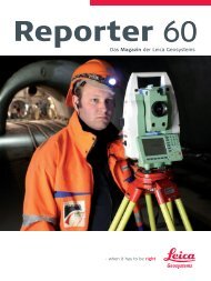
Precision Concrete<br />
for 300 km/h Trains<br />
by Konrad Saal<br />
Modern railway infrastructure often presents<br />
technical challenges for developers and builders<br />
alike, since high-speed railway tracks have<br />
to withstand enormous forces and vibrations.<br />
This also applies to the 123 km section between<br />
Erfurt and Leipzig/Halle, which forms part of the<br />
new Intercity Express (ICE) link between Munich<br />
and Berlin. Deutsche Bahn AG customers will<br />
eventually be travelling along this stretch at<br />
speeds of up to 300 km/h (190 mph), completing<br />
their journeys to or from the German capital<br />
in four rather than the current six hours.<br />
The ICE will travel over six major bridges and<br />
through three tunnels, the longest being the<br />
twin-tube Finne Tunnel with a length of almost<br />
seven kilometers. The precise control of the<br />
concrete paver that provided the bed for the<br />
subsequent track construction through the tunnel<br />
was accomplished with total stations and<br />
the 3D machine control system PaveSmart 3D<br />
from <strong>Leica</strong> Geosystems.<br />
The required accuracy for the concrete substructure<br />
in the tunnel tubes, on which the slab track would later<br />
be installed, was ± 1 cm. The paver’s specified daily<br />
output was about 120 m per day. Gerhard Baumgartner,<br />
site manager responsible for the invert concrete<br />
and who has already had earlier positive experiences<br />
with <strong>Leica</strong> Geosystems 3D control systems says: “With<br />
<strong>Leica</strong> PaveSmart 3D, Scanlaser GmbH, the German<br />
distribution partner for <strong>Leica</strong> Geosystems machine<br />
control systems, offered the only system available on<br />
the market capable of supporting Gomaco as well as<br />
Wirtgen pavers. In the planning stage we were considering<br />
both manufacturers as suppliers. PaveSmart<br />
3D is able to access the manufacturer’s 3D interface<br />
on the machine.” <strong>Leica</strong> PaveSmart 3D supports<br />
“Plug & Pave” and therefore offers the advantage of<br />
being able to communicate with the paver’s interface<br />
using a simple cable connection, rather than having<br />
to install complex hydraulics. This also saves valuable<br />
time when setting up the system. Work on the trial<br />
length of invert concrete was started within just one<br />
day of installation.<br />
“The Scanlaser specialists were on site with the surveying<br />
engineers from Angermeier Ingenieure GmbH<br />
as the machine was being set up and together they<br />
ensured a smooth and reliable start to the invert<br />
concreting works,” confirms Baumgartner. Anger-<br />
12 | <strong>Reporter</strong>
meier Ingenieure had already used its <strong>Leica</strong> TPS1800<br />
total stations to support the driving of the Finne<br />
Tunnel. Consequently, there was no need for data<br />
conversion when preparing the paver control data.<br />
<strong>No</strong> Stringlines through the Tunnel<br />
3D machine control reduces the costs and complexity<br />
of two-sided stringline installation and maintenance.<br />
Baumgartner appreciates the systems’ advantages:<br />
“Stringlines would have had to be drilled inside<br />
the tunnel and would have considerably restricted<br />
machine and truck freedom of movement. By using<br />
the 3D control system and the <strong>Leica</strong> TPS1800 total<br />
stations for machine positioning, it was possible to<br />
completely dispense with the commonly used stringlines<br />
in the tunnel.”<br />
The Finne Tunnel project would hardly have been<br />
possible with stringlines: normally, trucks delivering<br />
material to the concrete slip form paver reverse<br />
along the tunnel. The longer the distance, the more<br />
difficult and time-consuming the journey becomes.<br />
Driving in forward and turning the vehicles around<br />
conventionally in the tunnel once they reached the<br />
paver was out of the question due to its narrowness.<br />
The solution was the installation of a turntable, which<br />
allowed the trucks to drive in forwards. An excavator<br />
was then able to distribute the tipped material evenly<br />
in front of the slipform paver. Stringlines would constantly<br />
have been damaged or destroyed. The construction<br />
site management estimates that removing<br />
the need for stringlines saved between EUR 10,000<br />
– 20,000 on the costs of materials and installation.<br />
Objectives and Requirements Exceeded<br />
Since its initial installation at the beginning of<br />
<strong>No</strong>vember 2009 there has not been a single system<br />
failure. Control measurements confirm that the surface<br />
of the installed concrete has always been within<br />
the specified height tolerances. “The achieved vertical<br />
accuracy of ± 3 mm has by far outperformed the<br />
required accuracy of max. ± 1 cm,” report both Gerhard<br />
Baumgartner and the surveying engineers from<br />
Angermeier Ingenieure GmbH. Higher productivity is<br />
a further advantage of 3D control: the installation<br />
speed of the concrete invert was around 10 per cent<br />
higher than the required speed of 120 m/day.<br />
Finne Tunnel<br />
The Finne Tunnel is being constructed for Deutsche<br />
Bahn AG by a consortium comprising Wayss & Freytag<br />
Ingenieurbau AG, Max Bögl Bauunternehmung GmbH<br />
Co. KG, and Porr Technobau und Umwelt GmbH.<br />
The two tunnels were driven at the same time<br />
using shield tunnel boring machines with continuous<br />
installation of tubbing segments as a single-shell<br />
tunnel lining. Some 48,000 tubbing ring segments<br />
were manufactured on site in a specially set up tubbing<br />
segment production facility. The two tubes<br />
each have a diameter of approximately 10 meters.<br />
The profile and the formwork through which the<br />
concrete slips “as if cast in one pour” during paving<br />
is shaped to form side shoulders and a drainage<br />
channel. The advantage of this process is that the<br />
drainage elements and shoulders do not have to be<br />
built separately, increasing the stability of the entire<br />
construction.<br />
Other tunnel works to date include 16 cross passages<br />
for rescue routes and technical galleries driven<br />
using the New Austrian Tunneling Method (NATM).<br />
In a separate step after the concrete invert, the paver<br />
will be driven through the tunnel again to form a<br />
walkway on one side and a cable duct chamber on<br />
the other using conventional techniques.<br />
About the Author:<br />
Konrad Saal is a surveying engineer and Marketing<br />
Communications Manager with <strong>Leica</strong> Geosystems in<br />
Heerbrugg, Switzerland.<br />
More information about the entire project at:<br />
www.vde8.de<br />
The Global Magazine of <strong>Leica</strong> Geosystems | 13
Searching for<br />
Bombs Under Water<br />
by Alexander Gerber<br />
An estimated 7,000 bombs were dropped on<br />
Dresden during the Second World War. While<br />
most of them brought death and destruction,<br />
many still lie underground or in the Elbe river<br />
– without having detonated – and continue to<br />
pose a danger to construction projects even<br />
today, some 65 years later. Matthäi used the<br />
state-of-the-art <strong>Leica</strong> RedLine series satellitebased<br />
machine control system to search for<br />
undetonated Second World War bombs on and<br />
around the site for the new Waldschlösschen<br />
bridge over the Elbe.<br />
The Matthäi Group, a construction contractor with<br />
headquarters in Verden, Germany, specializes in<br />
earthworks, civil and structural engineering. The<br />
firm's hydraulic engineering department was restructured<br />
some years ago under the leadership of Dipl.-<br />
Ing. Jörn Adameit and has since then completed many<br />
successful projects on Europe's inland waterways.<br />
During the construction of the new bridge, the contract<br />
for the unusual task of searching the Elbe deposits<br />
for bombs was awarded to Berlin-based Heinrich<br />
Hirdes Kampfmittelräumung GmbH, supported by the<br />
state-of-the-art satellite-based dredging expertise<br />
provided by the hydraulic engineering department at<br />
Matthäi Bauunternehmung GmbH & Co. KG, Verden.<br />
Prior to construction, the river was scanned with<br />
probes that captured the positions of any detected<br />
metal objects to centimeter accuracy, measured their<br />
depths using echo sound, and plotted the findings in<br />
a digital model. This model was passed to Matthäi for<br />
the underwater excavation works. At about 60 locations<br />
the munitions divers then had to verify whether<br />
the detected objects were in fact dangerous legacies<br />
of the war or not.<br />
Markus Gehring, responsible for positioning and<br />
excavator engineering, as well as for the creation of<br />
the hydraulic engineering department’s data model,<br />
has already fitted out five excavators with the <strong>Leica</strong><br />
RedLine series GNSS positioning system. These systems<br />
were acquired from <strong>Leica</strong> Geosystems machine<br />
control sales and service partner Scanlaser GmbH:<br />
14 | <strong>Reporter</strong>
“We have been using this system for more than a<br />
year in all conditions. It is a reliable, modular system<br />
that offers me great flexibility, either as a reference<br />
station on site or, as for this hydraulic engineering<br />
job, on the machine.” Each excavator is equipped<br />
with two <strong>Leica</strong> MNA1202GG antennas and <strong>Leica</strong><br />
PowerBox GNSS receivers, which calculate positions<br />
from satellite data and transmit this information to<br />
the machine controls.<br />
This two-antenna solution has proved ideal for working<br />
underwater, as directional information is automatically<br />
obtained and the bucket position is recognized<br />
even on moving platforms such as here on<br />
the pontoon. The excavator driver always knows the<br />
current 3D position in real time. This data is compared<br />
with the positions of the objects in question<br />
recorded on the location drawing. Instead of a bucket,<br />
the excavator is fitted with a caisson in which the<br />
munitions divers, protected from the current, can<br />
be lowered to the location to be investigated – precisely,<br />
thanks to the GNSS data. “We receive the correction<br />
data for accurate positioning by radio from<br />
the reference station or by dialing into the reference<br />
service,” explains Markus Gehring. This allows the<br />
divers to be submerged up to three meters into the<br />
Elbe at the locations of the detected metal objects<br />
with centimeter accuracy.<br />
“The detonation of a bomb during the construction<br />
work for the new Waldschlösschen bridge would be<br />
a catastrophe. Thank goodness, so far the metal<br />
objects we have found have been nothing more than<br />
steel scrap,” says Martin Kralicek, Matthäi's site manager.<br />
A perfectly functioning system and good service<br />
are crucial for such a dangerous mission. “The<br />
excellent, comprehensive service was one of the reasons<br />
for selecting the <strong>Leica</strong> RedLine system and for<br />
working with Scanlaser.”<br />
About the author:<br />
Alexander Gerber is a Sales Engineer at <strong>Leica</strong><br />
Geosystems’ German machine control distribution<br />
partner Scanlaser GmbH.<br />
The Global Magazine of <strong>Leica</strong> Geosystems | 15
Gateway to Korea<br />
by Joël van Cranenbroeck<br />
The Yeong-Jong New Airport Highway Bridge, a<br />
steel, double deck, box-girder suspension bridge,<br />
links Incheon International Airport to Seoul city<br />
as a real gateway to Korea. It is the world’s first<br />
3D self-anchored suspension bridge servicing a<br />
highway on the upper/lower decks and a railway<br />
on the lower deck. The bridge crosses the<br />
sea between Yeong-Jong island and Incheon city<br />
and lies between Kyeongseo-dong (Changdo)<br />
and Unbuk-dong (Yeong-Jong island) of Incheon<br />
city on the Yellow Sea. <strong>Leica</strong> Geosystems was<br />
invited by the New Airport Highway Company<br />
to perform a load test with GNSS RTK technology.<br />
Equipment and software completed the<br />
test smoothly, achieving impressive accuracies<br />
in the range of 1 cm. This load test convincingly<br />
vindicated the superiority of GNSS based bridge<br />
monitoring. After the test the upgrade and<br />
modification of the structural health monitoring<br />
system was completed using a GNSS monitoring<br />
system from <strong>Leica</strong> Geosystems that focuses<br />
on monitoring the girder geometry and the displacement<br />
of the bridge towers.<br />
With <strong>Leica</strong> Geosystems GNSS RTK technology, the<br />
geometric structure of the bridge can be monitored<br />
in real-time and in all weather conditions. The threedimensional<br />
displacement of towers, main span, and<br />
suspension cables can be measured directly. All of this<br />
characteristic information reflecting bridge health can<br />
be combined with structural models to analyze the<br />
internal forces affecting the static and dynamic load<br />
components of the bridge.<br />
The reliability of bridge health monitoring and evaluation<br />
can be increased and the risk of potential damage<br />
to the bridge structure minimized. GNSS monitoring<br />
can considerably improve the efficiency and effective-<br />
16 | <strong>Reporter</strong>
Monitoring Equipment<br />
and Software<br />
Hardware<br />
2 <strong>Leica</strong> AT504 GG choke ring antennas<br />
2 <strong>Leica</strong> GRX1200 GG Pro reference station receivers<br />
10 <strong>Leica</strong> GMX902 GG monitoring receivers<br />
10 <strong>Leica</strong> AX1202 GG antennas<br />
Software<br />
<strong>Leica</strong> GNSS Spider GNSS reference network<br />
controlling and operating software<br />
<strong>Leica</strong> GNSS QC GNSS Quality Control<br />
and Monitoring software<br />
3rd party analysis software<br />
ness of maintenance work by providing vital information<br />
to management and decision makers for bridge<br />
traffic and structural safety. With the ongoing development<br />
and improvement of GNSS hardware, processing<br />
algorithms, and software <strong>Leica</strong> Geosystems’<br />
GNSS monitoring systems will be used ever more<br />
widely for the monitoring of infrastructure such as<br />
bridges, buildings, and other structures in the future.<br />
Meanwhile, the Yeong-Jong bridges’ structural health<br />
monitoring system plays an active role in the promotion<br />
and development of digital and intelligent bridge<br />
engineering.<br />
The GNSS bridge deformation monitoring system<br />
consists of GNSS sensors; seismic and temperature<br />
sensors; dual-axis inclinations sensors; communication<br />
links; and processing, management, and analysis<br />
software. All these components form an integrated<br />
system. When designing the system, the environmental<br />
situation was considered to be the predominant<br />
source of error. Multipath is caused by signals<br />
arriving at the antenna which have been reflected<br />
by nearby metal objects, ground, or water surfaces.<br />
The occurrence of this is different at each measuring<br />
site and therefore cannot be eliminated by differential<br />
techniques. At the reference station sites,<br />
a suitable location of the antenna was selected to<br />
mitigate such reflections. The <strong>Leica</strong> AT504 GG choke<br />
ring geodetic GNSS antenna helps reduce multipath<br />
effects. Several more GNSS receivers and antennas<br />
were installed (see box) to monitor bridge health. They<br />
are all connected to <strong>Leica</strong> GNSS Spider software and<br />
<strong>Leica</strong> GNSS QC for advanced coordinate analysis of the<br />
entire system.<br />
Two GNSS reference stations were established in stable<br />
areas. As the start point of each baseline, it is vital<br />
that the reference stations have precise coordinates<br />
within the local coordinate system. One reference station<br />
was installed on the roof of the Bridge Monitoring<br />
Center, the other at the west side of the bridge. To<br />
visualize the deflection and its impact on the bridge,<br />
another 10 GNSS monitoring points were installed.<br />
These were placed on the two bridge towers; the<br />
maximum flexibility point of the main span; the 1/9,<br />
2/9, 4/9, 8/9, and 9/9 points of the bridge; and on<br />
the cable. <strong>No</strong>w, using the transformation parameters<br />
provided by the owner, the system provides threedimensional<br />
dynamic displacement results within the<br />
bridge coordinate system.<br />
>><br />
The Global Magazine of <strong>Leica</strong> Geosystems | 17
<strong>Leica</strong> GNSS Spider also provides an interface for third<br />
party analysis software via the serial and TCP/IP ports.<br />
Any analysis software that uses standard NMEA format<br />
can be used. With real time bridge coordinates,<br />
the analysis software can display a dynamic view of<br />
the distortion curve, store data, and execute statistical<br />
analysis and messaging in real time. Moreover,<br />
<strong>Leica</strong> GNSS QC quality control and analysis software<br />
can be used to do a comprehensive review of the<br />
results. It proved to be an indispensable tool for<br />
checking data and results in the design and operational<br />
stages.<br />
20 Hz measurement rate, the bridge monitoring system<br />
is able to detect high frequency vibrations. To<br />
enhance overall reliability and stability, and according<br />
to the recommendations made by <strong>Leica</strong> Geosystems,<br />
the Yeong-Jong bridge monitoring system has two reference<br />
stations. <strong>Leica</strong> GNSS Spider supports multiple<br />
reference stations to enable redundant checks. If the<br />
communication to one reference station breaks down,<br />
the other reference station can be used as a backup<br />
for processing any combination of baselines. <strong>Leica</strong><br />
GNSS Spider can process observations from both L1<br />
single-frequency and L1+L2 dual-frequency GNSS<br />
receivers. Thus a single-frequency GNSS receiver can<br />
also be used for the bridge monitoring application in a<br />
low motion mode.<br />
The installation of the GNSS monitoring system was<br />
realized by <strong>Leica</strong> Geosystems Korea. The integration<br />
of the system into the structural health monitoring<br />
solution that includes more than 250 other sensors<br />
was carried out by BT Engineering South Korea.<br />
Monitoring display for analysis.<br />
<strong>Leica</strong> GNSS Spider – the link between the<br />
sensors and the monitoring system<br />
Communication requirements are greatly simplified<br />
through <strong>Leica</strong> GNSS Spiders’ centralized RTK concept.<br />
Receiver equipment can be remotely controlled and<br />
monitored, and the status of the entire monitoring<br />
system can be obtained at anytime. Operating at a<br />
About the Author:<br />
Joël van Cranenbroeck is Business Development Manager<br />
for Geodetic Monitoring at <strong>Leica</strong> Geosystems AG,<br />
Heerbrugg, Switzerland. He has led the development<br />
of hardware and software solutions for GNSS Network<br />
RTK for <strong>Leica</strong> Geosystems since 2001 and has made<br />
some significant contributions in Geodetic Monitoring<br />
development and applications such as the method<br />
statement for aligning along vertical high rise structures<br />
(Burj Dubai).<br />
The Yeong-Jong Bridge<br />
The construction of the Yeong-Jong bridge began<br />
in December 1993. The bridge was completed and<br />
opened to traffic in <strong>No</strong>vember 2000. The total length<br />
of the bridge and main span of the suspension bridge<br />
is 4,420 m and 550 m, respectively. The bridge is 35 m<br />
wide and has 49 piers. The east and west towers are<br />
107 m high. The bridge is divided into three parts:<br />
suspension bridge (550 m), steel truss (2,250 m), and<br />
steel deck (1,<strong>62</strong>0 m).<br />
The Bridge Monitoring Center was built at the east<br />
side of the bridge (New Airport Highway office) and<br />
equipped with a fiber optic communication system,<br />
closed circuit television, information management<br />
system, message sign system, emergency call system,<br />
broadcast system, etc.<br />
18 | <strong>Reporter</strong>
Adventure<br />
Surveying<br />
on Mont Blanc<br />
by Hélène Leplomb and Farouk Kadded<br />
Every two years, the chartered land surveyors<br />
of Haute-Savoie and <strong>Leica</strong> Geosystems measure<br />
the elevation of Mont Blanc, the roof of Europe,<br />
the famous mountain straddling the Franco-Italian<br />
border.<br />
The aims of these technical and human expeditions<br />
are to provide the general public with an unusual<br />
insight into the profession of the chartered land surveyor,<br />
to test the reliability and precision of <strong>Leica</strong><br />
Geosystems’ GNSS in difficult conditions, and to<br />
contribute to helping the scientific community provide<br />
answers to questions concerning variations in<br />
climate. Measuring the summit of Mont Blanc on a<br />
regular basis provides glaciologists, geographers,<br />
nivologists (snow experts), and meteorologists with<br />
data on the variations of a glacier at its source.<br />
With the GNSS measurements taken in September<br />
2009 at the summit under the supervision of Farouk<br />
Kadded, Product Manager at <strong>Leica</strong> Geosystems in<br />
France, it is possible to determine the mountains'<br />
elevation and to create a 3D model of the ice sheet.<br />
The 5 th measurement expedition to this superb<br />
experimentation site confirmed once more the reliability<br />
and robustness of the <strong>Leica</strong> SmartRover realtime<br />
GNSS receiver, which provided measurements<br />
to within one centimeter in the harsh conditions of<br />
high altitude and freezing temperatures. The <strong>Leica</strong><br />
Geoystems team was hardly surprised since this was<br />
the 4 th <strong>Leica</strong> Geosystems instrument to be subjected<br />
to such extreme conditions, following in the footsteps<br />
of the <strong>Leica</strong> GPS500 in 2001 and 2003, the<br />
<strong>Leica</strong> GPS1200 in 2005, and the <strong>Leica</strong> SmartStation<br />
in 2007.<br />
The Global Magazine of <strong>Leica</strong> Geosystems | 19
Accurate, Enriched<br />
Data at Lower Cost<br />
by Ann Hovland<br />
When the CH2M HILL survey team set out to<br />
map the City of Woodburn, Oregon’s 1,500 sewer<br />
manholes, the challenge was to gather and<br />
organize a varied group of data with a limited<br />
budget. For each manhole the client wanted:<br />
the pipe invert elevation; pipe size and type;<br />
documentation of condition; amount of debris;<br />
and photos. A traditional approach would have<br />
generated an inordinate number of notes that<br />
would have been difficult to organize and deliver<br />
within budget. After considering various<br />
products, the team chose <strong>Leica</strong> MobileMatriX<br />
on ArcGIS, a survey software that provided the<br />
team with geographic information system (GIS)<br />
capabilities and survey-grade accuracy in the<br />
field. The field integration of GIS enabled the<br />
team to complete all fieldwork 16 days ahead<br />
of schedule and 25 % under budget even while<br />
using MobileMatriX for the first time.<br />
Woodburn’s wastewater collection and transmission<br />
system had been under continual expansion since it<br />
was implemented. There was concern about localized<br />
areas and the City needed to evaluate the long-term<br />
condition and capacity of its collection and transmission<br />
system. In order to make sound investment decisions,<br />
the City needed a map of its system. Existing<br />
data about the collection system was stored in<br />
two separate systems and was known to be inaccurate<br />
and incomplete. The goals for mapping were:<br />
consolidate system asset data into a single GIS database<br />
and dramatically improve the accuracy of the<br />
spatial data.<br />
“While brainstorming a possible approach, we had<br />
the usual discussion about cost verses accuracy,” said<br />
20 | <strong>Reporter</strong>
1,500 manholes in 45 days<br />
The City of Woodburn’s decision to let the CH2M HILL<br />
survey team try a new approach to mapping its manholes<br />
yielded more accurate data, delivered within<br />
less time, and for less money than expected. The<br />
team’s original project plan allowed for 61 field days.<br />
Once the crew was in the field, progress increased<br />
exponentially as experience and confidence with <strong>Leica</strong><br />
MobileMatriX picked up. The crew estimated that it<br />
spent 25 % less time per manhole, and surveyed 170 %<br />
more manholes per day, than planned. They finished<br />
all fieldwork within 45 days, 25 % under budget. “We<br />
took a chance with having to learn and use new software<br />
on a job that needed a quick turn around, but<br />
that risk paid off in the end,” said Adam Casalegno.<br />
Tony Brooks, PLS, survey and mapping manager at<br />
CH2M HILL. “We talked about what competitors might<br />
propose. Many would likely suggest low-cost options<br />
that could not achieve the requested accuracies. Others<br />
would probably fulfill accuracy requirements and<br />
blow the budget. We wondered how we might find the<br />
middle ground.” The team was well aware of the fact<br />
that the most challenging aspect of the project was<br />
data integration. Successful integration of existing<br />
data and data integrity was crucial to project success<br />
because initial data acquisition and ongoing maintenance<br />
would otherwise become a time-consuming<br />
process. The team began to discuss the possibilities<br />
offered by a mobile GIS approach.<br />
With <strong>Leica</strong> MobileMatriX, the team estimated it<br />
could significantly reduce the workflow and costs by<br />
going directly from point collection to end product in<br />
one step. CH2M HILL rolled the dice and decided to<br />
propose an integrated GIS/survey approach to meet<br />
the client’s accuracy and budget requirements. The<br />
gamble paid off and the City had all of its data needs<br />
fulfilled, with money left over for additional survey<br />
tasks.<br />
Short Learning Curve with little Downtime<br />
To run the MobileMatriX software, the team needed a<br />
field-compatible computer, i.e. it needed to be rugged<br />
and minimize sunlight glare on the screen display. For<br />
these reasons, the team opted to use “electronic tablets”<br />
instead of laptops; the tablets also offered touch<br />
screen capability. CH2M HILL purchased an Xplorer<br />
tablet from Xplorer Technologies and loaded ArcGIS<br />
Version 9.2 and <strong>Leica</strong> MobileMatriX Version 3.0 onto<br />
it. The tablet had Bluetooth technology which could<br />
wirelessly send data back and forth between the <strong>Leica</strong><br />
GPS1200 and <strong>Leica</strong> TPS1200 instruments. The Xplorer<br />
tablet was purchased with an internal cell modem for<br />
Internet access to ORGN, the Oregon Real Time GPS<br />
Network, and the office network.<br />
The use of <strong>Leica</strong><br />
MobileMatriX for data<br />
acqusition and management<br />
of the waste water system<br />
saved CH2M HILL valuable<br />
time and money, as the<br />
survey data was directly<br />
integrated into the GIS.<br />
Once all the gear was assembled, the crew needed to<br />
learn how to use it. They contacted <strong>Leica</strong> Geosystems,<br />
who assigned a technician to the job of bringing<br />
>><br />
The Global Magazine of <strong>Leica</strong> Geosystems | 21
everyone up to speed. After a week of long phone<br />
calls and some trial and error, the tablets (and operators)<br />
were running smoothly. ”Like any new software,<br />
<strong>Leica</strong> MobileMatriX took some time to learn, but<br />
with help from <strong>Leica</strong> Geosystems technicians, the<br />
team was able pick it up quickly without much down<br />
time,” said Adam Casalegno, survey technician at<br />
CH2M HILL.<br />
Once in the field, with a GIS background of the sewer<br />
system at their fingertips, surveyors were able to<br />
quickly locate the manholes. The field crew collected<br />
the data and transferred it onto the portable tablet PC<br />
via <strong>Leica</strong> MobileMatriX, which linked data to the CH2M<br />
HILL office network version of the City’s functioning<br />
GIS database. The crew could work independent of<br />
the City’s database for long periods, then synchronize<br />
the office database with the updated field database<br />
later when a connection to the CH2M HILL office<br />
server could be made. Data changes were then transferred<br />
and integrated with the central database using<br />
the ArcGIS check-in process. This approach enabled<br />
the crew to manipulate, update, and add survey-grade<br />
information and synchronize it with office data in the<br />
field rather than having to upload data to a survey<br />
program and clean it up later. This reduced data cleanup<br />
time by approximately 70 %.<br />
Integrated Approach Streamlines Workflow<br />
Using the integrated survey/GIS approach the crew cut<br />
the number of workflow steps in half, and all clean up<br />
of data could be done in the field after each manhole<br />
was measured. <strong>Leica</strong> MobileMatriX provided full functionality<br />
for field crews to finish work in the field. The<br />
background maps, combined with the immediate map<br />
display and labeling of field measurements, enabled<br />
immediate feedback on the accuracy of measurements.<br />
<strong>No</strong> expensive re-measuring was required. The<br />
complete map could be finished in the field, including<br />
symbols, legends, and north arrows.<br />
About the Author:<br />
Ann Hovland, is a writer at CH2M HILL, a global leader<br />
in full-service engineering, consulting, construction,<br />
and operations.<br />
22 | <strong>Reporter</strong>
The <strong>Leica</strong> Lino Family:<br />
Everything Level and Perfectly Plumb<br />
The introduction of the <strong>Leica</strong> Lino 2 in 2007 set a<br />
new standard for cross line lasers, and in the same<br />
year received the Red Dot Product Design Award.<br />
Craftsmen appreciate the <strong>Leica</strong> Lino 2 because of its<br />
outstanding optics and the proven quality. Encouraged<br />
by this success, <strong>Leica</strong> Geosystems has created a<br />
comprehensive product palette around these handy<br />
tools and has recently expanded it with three point<br />
and line lasers that optimally cover all areas of application.<br />
The new <strong>Leica</strong> Lino P3, Lino P5, and Lino L2P5<br />
perfect all aligning, plumbing, and leveling tasks.<br />
The <strong>Leica</strong> Lino L2P5 combines all the advantages into<br />
one compact instrument. The five laser dots, exactly<br />
aligned at right angles to one another, simplify plumbing,<br />
setting out, and transfer of measured points.<br />
All <strong>Leica</strong> Lino point and line lasers project millimeteraccurate<br />
lines and/or dots, and automatically level<br />
themselves to compensate for minor angular misalignments<br />
of up to ± 4°. A comprehensive range of<br />
original accessories augments the standard product<br />
package.<br />
Function P3 P5 L2 L2P5<br />
Plumbing up and down X X X<br />
Setting out right angles X X<br />
Horizontal leveling X X X X<br />
Vertical alignment X X<br />
Vertical and horizontal alignment X X<br />
Aligning at an angle X X<br />
2009 <strong>Leica</strong> Geosystems HDS Worldwide<br />
User Conference: A Great Success<br />
<strong>Leica</strong> Geosystems 7 th annual worldwide user conference<br />
for users of its High-Definition Surveying<br />
(HDS) laser scanning products was held 26-28<br />
October 2009, in San Ramon, California. Despite the<br />
global recession, more than 250 participants from<br />
20 countries attended, a strong symbol of continued<br />
high interest in 3D laser scanning.<br />
The next HDS Worldwide User Conference is planned<br />
for 25-27 Oct <strong>2010</strong> in San Ramon. Find out more at<br />
www.leica-geosystems.com/hds.<br />
The conference featured 38 presentations, including<br />
a keynote by Dr. Dieter Fritsch, Director of the<br />
Institute for Photogrammetry and Remote Sensing,<br />
University of Stuttgart. Many presentations were by<br />
users describing their latest HDS applications, workflows,<br />
and marketing techniques in civil, buildings/<br />
BIM, plant, forensics, heritage, and mobile scanning<br />
markets. <strong>Leica</strong> Geosystems’ Dr. Greg Walsh gave an<br />
insightful presentation on the new, compact, “all-inone”<br />
laser scanner <strong>Leica</strong> ScanStation C10.<br />
The Global Magazine of <strong>Leica</strong> Geosystems | 23
www.leica-geosystems.com<br />
Australia<br />
CR Kennedy & Company Pty Ltd.<br />
Melbourne<br />
Phone +61 3 9823 1555<br />
Fax +61 3 9827 7216<br />
France<br />
<strong>Leica</strong> Geosystems Sarl<br />
Le Pecq Cedex<br />
Phone +33 1 30 09 17 00<br />
Fax +33 1 30 09 17 01<br />
Netherlands<br />
<strong>Leica</strong> Geosystems B.V.<br />
Wateringen<br />
Phone +31 88 001 80 00<br />
Fax +31 88 001 80 88<br />
Sweden<br />
<strong>Leica</strong> Geosystems AB<br />
Sollentuna<br />
Phone +46 8 <strong>62</strong>5 30 00<br />
Fax +46 8 <strong>62</strong>5 30 10<br />
Austria<br />
<strong>Leica</strong> Geosystems Austria GmbH<br />
Vienna<br />
Phone +43 1 981 22 0<br />
Fax +43 1 981 22 50<br />
Germany<br />
<strong>Leica</strong> Geosystems GmbH Vertrieb<br />
Munich<br />
Phone + 49 89 14 98 10 0<br />
Fax + 49 89 14 98 10 33<br />
<strong>No</strong>rway<br />
<strong>Leica</strong> Geosystems AS<br />
Oslo<br />
Phone +47 22 88 60 80<br />
Fax +47 22 88 60 81<br />
Switzerland<br />
<strong>Leica</strong> Geosystems AG<br />
Glattbrugg<br />
Phone +41 44 809 3311<br />
Fax +41 44 810 7937<br />
Belgium<br />
<strong>Leica</strong> Geosystems NV<br />
Diegem<br />
Phone +32 2 2090700<br />
Fax +32 2 2090701<br />
Hungary<br />
<strong>Leica</strong> Geosystems Hungary Kft.<br />
Budapest<br />
Phone +36 1 814 3420<br />
Fax +36 1 814 3423<br />
Poland<br />
<strong>Leica</strong> Geosystems Sp. z o.o.<br />
Warsaw<br />
Phone +48 22 338 15 00<br />
Fax +48 22 338 15 22<br />
United Kingdom<br />
<strong>Leica</strong> Geosystems Ltd.<br />
Milton Keynes<br />
Phone +44 1908 256 500<br />
Fax +44 1908 256 509<br />
Brazil<br />
Comercial e Importadora WILD Ltda.<br />
São Paulo<br />
Phone +55 11 3142 8866<br />
Fax +55 11 3142 8886<br />
India<br />
Elcome Technologies Private Ltd.<br />
Gurgaon (Haryana)<br />
Phone +91 124 4122222<br />
Fax +91 124 4122200<br />
Portugal<br />
<strong>Leica</strong> Geosystems, Lda.<br />
Moscavide<br />
Phone +351 214 480 930<br />
Fax +351 214 480 931<br />
UAE<br />
<strong>Leica</strong> Geosystems c/o Hexagon<br />
Dubai<br />
Phone +971 4 299 5513<br />
Fax +971 4 299 1966<br />
Canada<br />
<strong>Leica</strong> Geosystems Ltd.<br />
Willowdale<br />
Phone +1 416 497 2460<br />
Fax +1 416 497 8516<br />
Italy<br />
<strong>Leica</strong> Geosystems S.p.A.<br />
Cornegliano Laudense<br />
Phone + 39 0371 69731<br />
Fax + 39 0371 697333<br />
Russia<br />
<strong>Leica</strong> Geosystems OOO<br />
Moscow<br />
Phone +7 95 234 5560<br />
Fax +7 95 234 2536<br />
USA<br />
<strong>Leica</strong> Geosystems Inc.<br />
<strong>No</strong>rcross<br />
Phone +1 770 326 9500<br />
Fax +1 770 447 0710<br />
China P.R.<br />
<strong>Leica</strong> Geosystems AG,<br />
Representative Office Beijing<br />
Phone +86 10 8569 1818<br />
Fax +86 10 8525 1836<br />
Japan<br />
<strong>Leica</strong> Geosystems K.K.<br />
Tokyo<br />
Phone +81 3 5940 3011<br />
Fax +81 3 5940 3012<br />
Singapore<br />
<strong>Leica</strong> Geosystems Techn. Pte. Ltd.<br />
Singapore<br />
Phone +65 6511 6511<br />
Fax +65 6511 6500<br />
Denmark<br />
<strong>Leica</strong> Geosystems A/S<br />
Herlev<br />
Phone +45 44 54 02 02<br />
Fax +45 44 45 02 22<br />
Korea (Republic of)<br />
<strong>Leica</strong> Geosystems KK<br />
Seoul<br />
Phone +82 2 598 1919<br />
Fax +82 2 598 9686<br />
South Africa<br />
Hexagon Geosystems Pty.Ltd.<br />
Douglasdale<br />
Phone +27 1146 77082<br />
Fax +27 1146 53710<br />
Finland<br />
<strong>Leica</strong> Nilomark OY<br />
Espoo<br />
Phone +358 9 6153 555<br />
Fax +358 9 5022 398<br />
Mexico<br />
<strong>Leica</strong> Geosystems S.A. de C.V.<br />
Mexico D.F.<br />
Phone +525 563 5011<br />
Fax +525 611 3243<br />
Spain<br />
<strong>Leica</strong> Geosystems, S.L.<br />
Barcelona<br />
Phone +34 934 949 440<br />
Fax +34 934 949 442<br />
Illustrations, descriptions, and technical data are not binding. All rights reserved. Printed in Switzerland.<br />
Copyright <strong>Leica</strong> Geosystems AG, Heerbrugg, Switzerland, <strong>2010</strong>. 741803en – III.10 – RVA<br />
Head Office<br />
<strong>Leica</strong> Geosystems AG<br />
Heinrich-Wild-Strasse<br />
CH-9435 Heerbrugg<br />
Phone +41 71 727 31 31<br />
Fax +41 71 727 46 74<br />
www.leica-geosystems.com