Hammerfall® DSP System Multiface
Hammerfall® DSP System Multiface
Hammerfall® DSP System Multiface

You also want an ePaper? Increase the reach of your titles
YUMPU automatically turns print PDFs into web optimized ePapers that Google loves.
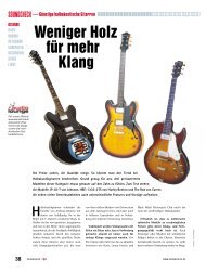
Use this unique moment and have a look at the internal design of the <strong>Multiface</strong>. On the right<br />
side of the lower printed circuit board (PCB) you can see the two switching power supplies.<br />
They generate both 5 Volts (for the digital circuitry) and ±13 Volts (for the analog circuitry) from<br />
nearly every possible input voltage. In the center you'll see the heart of the <strong>Multiface</strong>, the Xilinx<br />
FPGA. The analog circuitry and DA-converter for the headphone output is located on the right<br />
from the FPGA. Left from the FPGA two Low Jitter PLLs can be seen. On the outer left side<br />
you'll find 16 capacitors of the analog outputs and a 50-pin flat cable connector. The flat cable<br />
connects lower and upper board, the latter being the analog board, which is mounted downunder<br />
at the cover.<br />
The analog board is covered from a thin metalized shield, preventing noise from digital circuitry<br />
and flat cable being coupled into analog inputs and outputs. The shield is flexible and can be<br />
bended up, so that the view onto the analog board gets free.<br />
But now back to the jumper settings.<br />
6. Bend the flexible shield carefully upwards. You'll now see the analog board with its 16<br />
jumpers for level settings.<br />
7. The jumpers controlling the sensitivity of the inputs are located directly behind each TRS<br />
input jack. They allow three different settings: Left (middle plus left pin), right (middle plus right<br />
pin), and without jumper. If the device is still placed with the front panel to the front, then Left<br />
means +4 dBu (factory default), right means Lo Gain, and without jumper means –10 dBV.<br />
8. The jumpers controlling the output level are located on the other side of the board, and are<br />
placed in pairs. The jumper more near to the center of the board is the one of the even channel<br />
(2/4/6/8). Again three settings are possible: Left (middle plus left pin), right (middle plus right<br />
pin), and without jumper. If the device is still placed with the front panel to the front, then Left<br />
means +4 dBu (factory default), right means Lo Gain, and without jumper means –10 dBV.<br />
A drawing showing the jumper position for each level setting is found on the left side<br />
(underneath the flat cable) on the analog board.<br />
To prevent the loss of jumpers in –10 dBV mode, we recommend not to remove them<br />
completely, but to mount them at the outside of the jumper (no connection to the center<br />
pin).<br />
Now you are ready to re-assemble the <strong>Multiface</strong>.<br />
9. Turn the cover to the left and move it back over the <strong>Multiface</strong>.<br />
Take care that the flat cable has the same accurate shape as when opening it. Else the flat<br />
cable will cause mechanical problems while re-assembling!<br />
10. Move the cover so that it is placed 2 centimeters (1 inch) above the housing. Tilt the cover<br />
so that the jacks point to the holes in the rear panel. Carefully slide the jacks into the holes by<br />
moving the cover away from you. When inserted completely into the rear panel, the cover can<br />
now be layed down.<br />
11. Re-fit the 6 screws into the cover, and re-fit and tighten both screws of the D-sub jack.<br />
That's it!<br />
User’s Guide H<strong>DSP</strong> <strong>System</strong> <strong>Multiface</strong> © RME 16