Hammerfall® DSP System Multiface
Hammerfall® DSP System Multiface
Hammerfall® DSP System Multiface

Create successful ePaper yourself
Turn your PDF publications into a flip-book with our unique Google optimized e-Paper software.
Buffer Size<br />
The setting ‘Buffer Size’ determines the latency between incoming and outgoing data, as well<br />
as affecting system stability. We recommend selecting the highest value here (8192 samples) -<br />
the board itself will still run comfortably.<br />
Options<br />
'Alt. ASIO Mode' activates a different ASIO callback method. This setting is performed in realtime<br />
and under operation. Therefore it's very easy to check whether this setting results in any<br />
performance advantages. This setting is recommended for Logic (emagic) and Spark (TC).<br />
SPDIF In<br />
Defines the input for the SPDIF signal. 'Coaxial' relates to the phono socket, 'ADAT' to the<br />
optical TOSLINK input.<br />
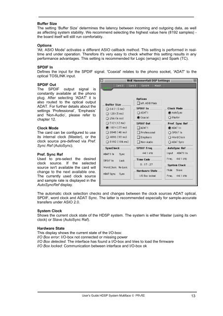
SPDIF Out<br />
The SPDIF output signal is<br />
constantly available at the phono<br />
plug. After selecting 'ADAT' it is<br />
also routed to the optical output<br />
ADAT. For further details about the<br />
settings ‘Professional’, ‘Emphasis’<br />
and ‘Non-Audio’, please refer to<br />
chapter 12.<br />
Clock Mode<br />
The card can be configured to use<br />
its internal clock (Master), or the<br />
clock source pre-defined via Pref.<br />
Sync Ref (AutoSync).<br />
Pref. Sync Ref<br />
Used to pre-select the desired<br />
clock source. If the selected<br />
source isn't available the card will<br />
change to the next available one.<br />
The currently used clock source<br />
and sample rate is displayed in the<br />
AutoSyncRef display.<br />
The automatic clock selection checks and changes between the clock sources ADAT optical,<br />
SPDIF, word clock and ADAT Sync. The latter is recommended especially for sample-accurate<br />
transfers under ASIO 2.0.<br />
<strong>System</strong> Clock<br />
Shows the current clock state of the H<strong>DSP</strong> system. The system is either Master (using its own<br />
clock) or Slave (AutoSync Ref).<br />
Hardware State<br />
This display shows the current state of the I/O-box:<br />
I/O Box error: I/O-box not connected or missing power<br />
I/O Box detected: The interface has found a I/O-box and tries to load the firmware<br />
I/O Box locked: Communication between interface and I/O-box ok<br />
User’s Guide H<strong>DSP</strong> <strong>System</strong> <strong>Multiface</strong> © RME 13