Hammerfall® DSP System Multiface
Hammerfall® DSP System Multiface
Hammerfall® DSP System Multiface

You also want an ePaper? Increase the reach of your titles
YUMPU automatically turns print PDFs into web optimized ePapers that Google loves.
User’s Guide - Macintosh<br />
Hammerfall ® <strong>DSP</strong> <strong>System</strong><br />
<strong>Multiface</strong><br />
The most compact professional multitrack recording system ever!<br />
24 Bit / 96 kHz ��<br />
TotalMix <br />
SyncAlign ® ZLM ® SyncCheck ®<br />
PCI Busmaster Digital I/O <strong>System</strong><br />
PCI and CardBus Interface<br />
2 + 24 Channels Stereo / ADAT Interface<br />
24 Bit / 96 kHz Analog Stereo Monitor<br />
ADAT Sync In
Contents<br />
1 Introduction............................................................ 3<br />
2 Package Contents .................................................. 3<br />
3 <strong>System</strong> Requirements............................................ 3<br />
4 Brief Description and Characteristics................... 4<br />
5 Technical Specifications<br />
5.1 Digital.................................................................... 4<br />
5.2 Analog................................................................... 4<br />
5.3 Transfer Modes: Resolution/Bits per Sample......... 5<br />
5.4 Power supply......................................................... 5<br />
6 Hardware Installation<br />
6.1 PCI Interface......................................................... 6<br />
6.2 CardBus Card........................................................ 6<br />
7 Software Installation .............................................. 7<br />
8 Operation and Usage<br />
8.1 Connections .......................................................... 9<br />
8.2 Recording Digital ................................................. 10<br />
8.3 Recording Analog ................................................ 10<br />
8.4 Analog Inputs ...................................................... 11<br />
8.5 Analog Outputs.................................................... 11<br />
9 Configuring the <strong>Multiface</strong><br />
9.1 General Information............................................. 12<br />
9.2 Clock Modes - Synchronization............................ 14<br />
9.3 Changing the Jumper Settings............................. 15<br />
10 Word Clock<br />
10.1 Technical Description and Usage....................... 17<br />
10.2 Cables and Termination..................................... 17<br />
10.3 General Operation ............................................. 18<br />
11 Using more than one Hammerfall <strong>DSP</strong> ............... 18<br />
12 Special Characteristics of the SPDIF Output...... 18<br />
13 Operation under ASIO 2.0<br />
13.1 General ............................................................. 19<br />
13.2 Performance...................................................... 19<br />
13.3 Synchronization................................................. 20<br />
13.4 Known Problems................................................ 20<br />
14 TotalMix: Routing and Monitoring<br />
14.1 Elements of the Surface .................................... 21<br />
14.2 Tour de TotalMix ............................................... 22<br />
14.3 Submix View ..................................................... 23<br />
14.4 Mute and Solo ................................................... 23<br />
14.5 Hotkeys ............................................................. 23<br />
14.6 Quick Access Panel........................................... 24<br />
14.7 Presets .............................................................. 25<br />
14.8 Level Meter ....................................................... 26<br />
15 Notes on Laptops and CardBus .......................... 27<br />
16 Hotline - Troubleshooting<br />
16.1 General ............................................................. 28<br />
16.2 Installation......................................................... 29<br />
17 Software and Hardware Compatibility ................ 29<br />
18 Accessories .......................................................... 30<br />
19 TECH INFO ........................................................... 31<br />
20 Warranty ............................................................... 32<br />
21 Appendix............................................................... 32<br />
22 Diagrams<br />
22.1 Block Diagram <strong>Multiface</strong>.................................... 33<br />
22.2 ADAT Track Routing, ASIO 96 kHz ................... 34<br />
22.3 Block Diagram TotalMix .................................... 35<br />
23 CE / FCC Compliance........................................... 36<br />
User’s Guide H<strong>DSP</strong> <strong>System</strong> <strong>Multiface</strong> © RME 2
1. Introduction<br />
Thank you for choosing the Hammerfall <strong>DSP</strong>. This unique audio system is capable of<br />
transferring digital audio data directly to a computer from practically any device equipped with<br />
a digital audio interface, be it S/PDIF, AES/EBU or ADAT optical. The numerous unique<br />
features and well thought-out configuration dialog puts the Hammerfall <strong>DSP</strong> at the very top of<br />
the range of digital audio interface cards.<br />
The package includes drivers for Windows 98/2000/XP and MacOS. An ALSA driver for Linux<br />
is planned to be available soon (see chapter 7).<br />
Our high-performance philosophy guarantees maximum system performance by executing all<br />
functions directly in hardware and not in the driver (i.e. the CPU).<br />
2. Package Contents<br />
Please check that your Hammerfall <strong>DSP</strong> <strong>System</strong>s package contains each of the following:<br />
PCI Interface:<br />
• PCI card H<strong>DSP</strong><br />
• Quick Info guide<br />
• RME Driver CD<br />
• Cable IEEE1394, 4.5 m (15 ft)<br />
• Internal cable (3 pin)<br />
CardBus Interface:<br />
• CardBus card<br />
• Quick Info guide<br />
• RME Driver CD<br />
• Cable CardBus to IEEE1394, 4.5 m (15 ft)<br />
• 12 V car cable<br />
• Battery cable<br />
• Power supply 12 V / 1.25 A and power cord<br />
<strong>Multiface</strong>:<br />
• I/O-box <strong>Multiface</strong><br />
• Quick Info guide<br />
• RME Driver CD<br />
• 1 optical cable (TOSLINK), 2 m (6.6 ft)<br />
3. <strong>System</strong> Requirements<br />
• MacOS 8.6 or greater. G3 300 MHz recommended<br />
• PCI Interface: a free PCI rev. 2.1 Busmaster slot<br />
• CardBus Interface: a free PCMCIA Slot type II, CardBus-compatible<br />
Note: Information on compatibility and performance of notebooks/laptops is included in RMEs<br />
Tech Infos about notebooks, H<strong>DSP</strong> <strong>System</strong> – Notebook Basics and Tests.<br />
User’s Guide H<strong>DSP</strong> <strong>System</strong> <strong>Multiface</strong> © RME 3
4. Brief Description and Characteristics<br />
• Hammerfall design: 0% (zero!) CPU load, even using all 26 ASIO channels<br />
• All settings can be changed in real-time<br />
• Enhanced mixed mode: ADAT In, S/PDIF In, and all outputs can be used simultaneously<br />
• 8 available buffer sizes/latencies: 1.5 / 3 / 6 / 12 / 23 / 46 / 93 / 186 ms<br />
• Sample Split technology for 4 channel, 96 kHz/24-bit record/playback via ADAT optical<br />
• Slave and master clock modes<br />
• Automatic and intelligent master/slave clock control<br />
• Unsurpassed Bitclock PLL (audio synchronization) in ADAT mode<br />
• Word clock input and output<br />
• ADAT Sync in (9-pin D-type) for sample-accurate transfer<br />
• Zero Latency Monitoring: Hardware bypass per track, controlled by Punch in/out<br />
• Enhanced ZLM for latency-free submixes and perfect ASIO Direct Monitoring<br />
• SyncAlign guarantees sample aligned and never swapping channels<br />
• SyncCheck tests and reports the synchronization status of input signals<br />
• 1 x MIDI I/O, 16 channels high-speed MIDI<br />
• 1 x Analog Line/headphone output, separate output for independent submix<br />
• DIGICheck <strong>DSP</strong>: Level meter in hardware, peak- and RMS calculation<br />
• TotalMix: 720 channel mixer with 40 bit internal resolution<br />
5. Technical Specifications<br />
5.1 Digital<br />
• Super Low Jitter Design: < 3 ns word clock PLL, < 2 ns ADAT PLL, < 1 ns internal<br />
• Internal sample rates: 32 / 44.1 / 48 / 88.2 / 96 kHz<br />
• Supported sample rats through word clock: 27 kHz - 103 kHz<br />
• Internal resolution: 24 Bit<br />
• Input PLL ensures zero dropout, even at more than 40 ns jitter<br />
• Bitclock PLL for trouble-free varispeed operation in ADAT mode<br />
• High-sensitivity input stage (< 0.2 Vss input level)<br />
• Output voltage 0.8V (consumer mode, phono) or 2.3V (professional mode)<br />
• Phono input and output ground-free transformer coupled<br />
• Connectors: optical (TOSLINK), phono, BNC<br />
• Clocks: ADAT Sync In, word clock I/O<br />
• Formats: SPDIF (Consumer and Professional), ADAT optical<br />
5.2 Analog<br />
Stereo Monitor Output<br />
• Analog output level +8 dBu @ 0 dBFS<br />
• Dynamic range: 108 dB (RMS unweighted, unmuted), 112 dBA<br />
• THD+N: -100 dB / 0.001%<br />
• Frequency response DA, -0.1 dB: 20 Hz - 20.8 kHz (sf 44,1 kHz)<br />
• Frequency response DA, -0.5 dB: 10 Hz - 44 kHz (sf 96 kHz)<br />
• Sample rates playback: 32 / 44.1 / 48 / 64 / 88.2 / 96 kHz and variable (word clock)<br />
• Ouput impedance: 75 Ohm<br />
• Channel separation: > 110 dB<br />
User’s Guide H<strong>DSP</strong> <strong>System</strong> <strong>Multiface</strong> © RME 4
AD<br />
• Resolution AD: 24 Bit<br />
• Signal to Noise ratio: 101 dB RMS unweighted, 106 dBA<br />
• THD: < -107 dB, < 0.00045 %<br />
• THD+N: < -96 dB, < 0.0016 %<br />
• Crosstalk: > 120 dB<br />
• Analog headroom prior to AD conversion: 13 dB<br />
• Frequency response AD @ 44.1 kHz, -0.5 dB: 5 Hz - 20.7 kHz<br />
• Frequency response AD @ 96 kHz, -0.5 dB: 5 Hz - 32 kHz<br />
• Input Line: 1/4" TRS jack, servo balanced<br />
• Input impedance Line: > 5 kOhm<br />
• Input sensitivity through jumper: Lo Gain, +4 dBu, -10 dBV<br />
• Input level for 0 dBFS @ Lo Gain: +19 dBu<br />
• Input level for 0 dBFS @ +4 dBu: +13 dBu<br />
• Input level for 0 dBFS @ -10 dBV: +2 dBV<br />
DA<br />
• Resolution DA: 24 Bit<br />
• Signal to Noise ratio: 108 dB RMS unweighted, 111 dBA (unmuted)<br />
• THD: < - 98 dB, < 0.0013 %<br />
• THD+N: < -91 dB, < 0.002 %<br />
• Crosstalk: > 100 dB<br />
• Maximum output level DA: +19 dBu<br />
• Frequency response DA @ 44.1 kHz, -0.5 dB: 5 Hz – 20.9 kHz<br />
• Frequency response DA @ 96 kHz, -0.5 dB: 5 Hz - 35 kHz<br />
• Output Line: 1/4" TRS jack, servo balanced<br />
• Output impedance Line: 47 Ohm<br />
• Output level through jumper: Hi Gain, +4 dBu, -10 dBV<br />
• Output level at 0 dBFS @ Hi Gain: +19 dBu<br />
• Output level at 0 dBFS @ +4 dBu: +13 dBu<br />
• Output level at 0 dBFS @ -10 dBV: +2 dBV<br />
5.3 Transfer Modes: Resolution / Bits per Sample<br />
• 32 bit, 4 byte (stereo 8 byte)<br />
This format is compatible with 16-bit and 20-bit. Resolutions below 24-bit are handled by the<br />
audio application. The card works internally with 32-bit data, but audio data transfer is limited to<br />
24-bits.<br />
5.4 Power supply<br />
• The CardBus card does not provide power to the attached I/O-box. Therefore a hi-tech<br />
switching power supply is included<br />
• The PCI card operates as power supply for the attached I/O-box<br />
The <strong>Multiface</strong> draws a high startup current of more than 2.5 A during initialisation. Current at 12<br />
Volt operating voltage: unloaded 500 mA (6 Watts), loaded 760 mA (9 Watts). Supply voltage<br />
range DC 7 V – 38 V, AC 7 V – 27 V.<br />
User’s Guide H<strong>DSP</strong> <strong>System</strong> <strong>Multiface</strong> © RME 5
6. Hardware Installation<br />
6.1 PCI Interface<br />
Before installing the PCI card, please make sure the computer is switched off and the<br />
power cable is disconnected from the mains supply. Inserting or removing a PCI card while<br />
the computer is in operation can cause irreparable damage to both motherboard and card!<br />
1. Disconnect the power cord and all other cables from the computer.<br />
2. Remove the computer's housing. Further information on how to do this can be obtained<br />
from your computer´s instruction manual.<br />
3. Important: Before removing the card from its protective bag, discharge any static in your<br />
body by touching the metal chassis of the PC.<br />
4. Insert the PCI card firmly into a free PCI slot, press and fasten the screw.<br />
5. Replace the computer's housing.<br />
6. Reconnect all cables including the power cord.<br />
7. Connect PCI interface and <strong>Multiface</strong> using the supplied cable (IEEE1394). This is a<br />
standard Firewire cable (6-pin).<br />
6.2 CardBus Card<br />
Before inserting the CardBus card make sure the complete H<strong>DSP</strong> system is ready for<br />
operation!<br />
1. Connect the CardBus card with the <strong>Multiface</strong> using the supplied cable.<br />
2. Insert the CardBus card with the Hammer logo up into a PCMCIA slot.<br />
3. Plug the power jack of the supplied switching power supply into the connector labeled AUX,<br />
on the rear of the <strong>Multiface</strong>.<br />
4. Connect power cord to power supply, plug into AC outlet. The green LED of the power<br />
supply and the red LED of the <strong>Multiface</strong> will light up.<br />
5. Switch on the notebook and boot the operating system.<br />
The small 15-pin connector of the CardBus card is coded. Only the supplied special cable<br />
can be plugged in, and only when the metal sleeve is up. Any kind of violence when<br />
plugging in and out can cause damage to the CardBus card.<br />
User’s Guide H<strong>DSP</strong> <strong>System</strong> <strong>Multiface</strong> © RME 6
7. Software Installation<br />
First fit the card (see 6. Hardware Installation), then switch on the computer and install the<br />
drivers from the RME Driver CD. The driver files are located on the CD in the folder<br />
'Hammerfall <strong>DSP</strong>'.<br />
In case a newer driver version was downloaded from the RME website double-click the<br />
'madsp_x.sit' archive to decompress it into separate files (using 'Aladin Stuffit Expander').<br />
If you already installed an older version of the driver first make sure to remove all old files.<br />
To do so open the 'Extensions' folder which is inside your '<strong>System</strong>' folder. Remove the file<br />
'Hammerfall <strong>DSP</strong> Driver'. Also remove 'Hammerfall <strong>DSP</strong> Settings' from the directory where it<br />
was copied to. Remove the 'Hammerfall <strong>DSP</strong> ASIO' driver file from any 'ASIO Drivers' folder.<br />
After unstuffing the archive the driver files are found in folders. The name of the folders tell<br />
where to copy the files! The driver installation is done manually in 5 steps:<br />
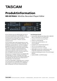
1. Drag the file Hammerfall <strong>DSP</strong><br />
Driver from 'into <strong>System</strong> folder'<br />
into the <strong>System</strong> folder. It will be<br />
installed automatically into the<br />
'Extension' folder. Confirm the<br />
system's message to complete<br />
the installation. Now the driver<br />
file should be found in the<br />
'Extension' folder, see example to<br />
the right.<br />
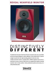
2. Copy the files Hammerfall <strong>DSP</strong> Settings,<br />
Hammerfall <strong>DSP</strong> ASIO and Hammerfall <strong>DSP</strong><br />
ASIO 96 kHz from 'into ASIO Drivers folder' into all<br />
'ASIO Drivers' folders found on your computer. As<br />
every ASIO software has its own ASIO Drivers<br />
folder, the files most propably have to be copied<br />
several times.<br />
Configuration of the Hammerfall <strong>DSP</strong> is done through the Settings dialog, which can be called<br />
from within any ASIO compatible software (for example Audio/<strong>System</strong>/ASIO Control Panel). To<br />
be able to call up the Settings dialog at any time we recommend to create an Alias on the<br />
desktop. To create an Alias select 'Hammerfall <strong>DSP</strong> Settings' with the mouse cursor, press and<br />
hold the Apple and Alt keys on your keyboard, and drag 'Hammerfall <strong>DSP</strong> Settings' to the<br />
desired location.<br />
User’s Guide H<strong>DSP</strong> <strong>System</strong> <strong>Multiface</strong> © RME 7
3. Copy the complete sub-folder Hammerfall <strong>DSP</strong>, found in the folder 'into Preferences folder',<br />
to the system folder 'Preferences'. This way the files related to the H<strong>DSP</strong> system reside in their<br />
own folder, without cluttering the Preferences folder. Additionally deleting those files is much<br />
easier in case of a driver update. Hammerfall <strong>DSP</strong> contains 10 files:<br />
default.mix: Default settings for TotalMix<br />
default.vol: Default settings for Digiface/<strong>Multiface</strong>, as long as TotalMix isn't started<br />
preset1.mix to preset8.mix: Presets for the H<strong>DSP</strong> mixer<br />
4. The file Hammerfall <strong>DSP</strong> TotalMix can be copied to any place. When started the H<strong>DSP</strong><br />
mixer comes up and allows you to configure the digital real-time mixer of the <strong>Multiface</strong>.<br />
TotalMix requires Carbon Library 1.1, which is part of the operating system since MacOS<br />
9.1. After installation of Carbon Library 1.1 TotalMix can even be run on older systems<br />
(down to 8.6).<br />
5. Using the MIDI port of the <strong>Multiface</strong> requires an installed OMS (Open Music <strong>System</strong>) from<br />
Opcode. The latest version 2.3.8 can be downloaded for free at<br />
http://www.opcode.com<br />
After the installation of OMS, copy the file H<strong>DSP</strong>_OMSDriver, found in the folder 'into OMS<br />
Folder folder', into the system folder 'OMS Folder'.<br />
To finish installation reboot the computer.<br />
After re-boot the MIDI driver is installed, but not yet activated. To activate it create a new OMS<br />
Studio setup. Using 'Search' the MIDI driver of the <strong>Multiface</strong> should be found and added to the<br />
list. Now it can be activated.<br />
Linux/Unix<br />
An ALSA driver for Linux/Unix is planned to be available soon. Further information on ALSA is<br />
available at<br />
http://www.alsa-project.org<br />
User’s Guide H<strong>DSP</strong> <strong>System</strong> <strong>Multiface</strong> © RME 8
8. Operation and Usage<br />
8.1 Connections<br />
The front of the I/O-box <strong>Multiface</strong> has the MIDI input and output, the analog stereo output of<br />
the digital mixer, and several status LEDs:<br />
MIDI State indicates sent or received data for the MIDI port<br />
Input State indicates a valid input signal separately for each input. RME’s exclusive<br />
SyncCheck shows through a blinking LED, which of the input signals is locked, but not in sync<br />
to the others. See chapter 9.2, Clock Modes - Synchronisation.<br />
The red HOST LED lights up when the power supply or the computer is switched on, thus<br />
signalling the presence of operating voltage. At the same time it operates as Error LED, in case<br />
the I/O-box wasn’t initialised, or the connection to the interface has been interrupted (Error,<br />
cable not connected etc.).<br />
Phones is a low impedance line output of highest quality, which can produce a sufficient<br />
volume undistorted even when used with headphones.<br />
The back of the <strong>Multiface</strong> has the 8 analog inputs and outputs, the power supply connector<br />
AUX (only needed in CardBus operation), and all digital inputs and outputs:<br />
ADAT I/O (TOSLINK), 1 to 3. The ADAT1 I/O can also be used for optical SPDIF, if this mode<br />
is selected in the Settings dialog.<br />
SPDIF I/O coaxial (phono)<br />
Word clock I/O (BNC)<br />
ADAT Sync In (D-sub 9-pin)<br />
The SPDIF inputs are selected via the Settings dialog (started by clicking on the hammer<br />
symbol in the system tray). The H<strong>DSP</strong> system accepts the commonly used digital audio<br />
formats, SPDIF as well as AES/EBU. Channel status and copy protection are ignored.<br />
In SPDIF mode, identical signals are available at both the optical and the coaxial outputs. An<br />
obvious use for this would be simply connecting two devices, i.e. using the H<strong>DSP</strong> as a splitter<br />
(distribution 1 on 2).<br />
To receive signals in AES/EBU format,<br />
an adapter cable is required. Pins 2 and 3<br />
of a XLR plug are connected individually<br />
to the two pins of a phono plug. The<br />
cable shielding is only connected to pin 1<br />
of the XLR - not to the phono plug.<br />
The ground-free design using transformers for digital inputs and outputs enables trouble-free<br />
connection even to AES/EBU devices, and perfect hum rejection.<br />
User’s Guide H<strong>DSP</strong> <strong>System</strong> <strong>Multiface</strong> © RME 9
8.2 Recording Digital<br />
Unlike analog soundcards which produce empty wave files (or noise) when no input signal is<br />
present, digital I/O cards always need a valid input signal to start recording.<br />
To take this into account, RME has included two unique features in the Hammerfall <strong>DSP</strong><br />
system: a comprehensive I/O signal status display (showing sample frequency, lock and sync<br />
status) in the Settings dialog, and status LEDs for each input.<br />
The sample frequency shown in the Settings dialog (see chapter 9, screenshot Settings) is<br />
useful as a quick display of the current configuration (the board itself and all connected external<br />
equipment). If no sample frequency is recognized, it will read ‘No Lock’.<br />
With this configuring any suitable audio application for digital recording is simple. After<br />
selecting the required input, Hammerfall <strong>DSP</strong> displays the current sample frequency. This<br />
parameter can then be changed in the application’s audio attributes (or similar) dialogue.<br />
It often makes sense to monitor the input signal or send it directly to the output. This can be<br />
done at zero latency using TotalMix (see chapter 14).<br />
For an automated real-time monitoring function the H<strong>DSP</strong> <strong>System</strong> supports ASIO Direct<br />
Monitoring (ADM) in ASIO 2.0. When 'ASIO Direct Monitoring' has been switched on the input<br />
signal is routed in real-time to the output whenever Record is started.<br />
8.3 Recording analog<br />
For recordings via the analog inputs the corresponding record channels have to be chosen.<br />
Apart from the internal jumpers which set the basic operating level, the <strong>Multiface</strong> has no means<br />
to change the input level. This would make no sense for the digital inputs, but also for the<br />
analog inputs one can do without it. It doesn't matter if the <strong>Multiface</strong> is operated at a mixing<br />
desk or a multichannel Mic preamp, in either case the level can be controlled directly at the<br />
source to match the <strong>Multiface</strong>'s sensitivity perfectly.<br />
The input sensitivity of the analog inputs can be changed through internal jumpers to meet the<br />
most often used studio levels, see next chapter.<br />
User’s Guide H<strong>DSP</strong> <strong>System</strong> <strong>Multiface</strong> © RME 10
8.4 Analog Inputs<br />
The <strong>Multiface</strong> provides 8 balanced Line inputs via 1/4" TRS (stereo) jacks. The electronic input<br />
stage is built in a servo balanced design which handles monaural and stereo jacks correctly.<br />
When used unbalanced it automatically corrects the gain by 6 dB.<br />
When using unbalanced cables with stereo TRS jacks, the 'ring' contact of the cable's jack<br />
should be connected to pin 1 (ground). Otherwise noise may occur, caused by the<br />
unconnected negative input of the balanced input.<br />
One of the main issues when working with an AD-converter is to maintain the full dynamic<br />
range within the best operating level. Therefore the <strong>Multiface</strong> includes internal jumpers which<br />
allow a perfect adaptation for all 8 channels seperately to the three most often used studio<br />
levels.<br />
The 'standardized' studio levels do not result in a (often desired) full scale level, but take some<br />
additional digital headroom into consideration. The amount of headroom is different in different<br />
standards and again differently implemented by different manufacturers. Because of this we<br />
decided to define the levels of the <strong>Multiface</strong> in a most compatible way.<br />
Reference 0 dBFS @ Headroom<br />
Lo Gain +19 dBu 15 dB<br />
+4 dBu +13 dBu 9 dB<br />
-10 dBV +2 dBV 12 dB<br />
The device ships with +4 dBu as factory default. The according headroom meets the latest<br />
EBU recommendations for Broadcast usage. At -10 dBV 12 to 15 dB headroom are common<br />
practice, each mixing desk operating at -10 dBV is able to send and receive much higher<br />
levels. Lo Gain allows to work with high levels, best suited for professional users who prefer to<br />
work balanced and at highest levels.<br />
Information on how to change the jumpers can be found in chapter 9.3.<br />
8.5 Analog Outputs<br />
The 8 short circuit protected, low impedance and servo balanced line outputs are available as<br />
(stereo) 1/4" TRS jacks. The electronic output stage is built in a servo balanced design which<br />
handles monaural and stereo jacks correctly. When used unbalanced it automatically corrects<br />
the gain by 6 dB.<br />
To maintain an optimum level for devices connected to the analog outputs, the <strong>Multiface</strong><br />
includes internal jumpers which allow to change the level of all 8 outputs separately. As with<br />
the analog inputs the analog output levels are defined to maintain a problem-free operation<br />
with most other devices. The table shown above is alos valid for the analog outputs. The<br />
device ships with +4 dBu as factory default.<br />
Information on how to change the jumpers can be found in chapter 9.3.<br />
User’s Guide H<strong>DSP</strong> <strong>System</strong> <strong>Multiface</strong> © RME 11
9. Configuring the Digiface<br />
9.1 General Information<br />
Configuring the H<strong>DSP</strong> system is done using its own settings dialog, the program Hammerfall<br />
<strong>DSP</strong> Settings.<br />
The Hammerfall <strong>DSP</strong>’s hardware offers a number of helpful, well thought-of practical functions<br />
and options which affect how the card operates - it can be configured to suit many different<br />
requirements. The following is available in the 'Settings' dialog:<br />
• Input selection<br />
• Output mode<br />
• Output channel status<br />
• Synchronization behaviour<br />
• Input and output status display<br />
• Time code display<br />
Any changes made in the Settings<br />
dialog are applied immediately -<br />
confirmation (e.g. by clicking on<br />
OK or exiting the dialog) is not<br />
required. However, settings should<br />
not be changed during playback or<br />
record if it can be avoided, as this<br />
can cause unwanted noises. Also,<br />
please note that even in 'Stop'<br />
mode, several programs keep the<br />
recording and playback devices<br />
open, which means that any new<br />
settings might not be applied<br />
immediately.<br />
The status displays at the bottom<br />
of the dialog box give the user<br />
precise information about the current status of the system, and the status of all signals.<br />
‘SyncCheck’ indicates whether there is a valid signal for each input (‘Lock’ or ‘No Lock’), or if<br />
there is a valid and synchronous signal (‘Sync’). The ‘AutoSync Ref’ display shows the input<br />
and frequency of the current sync source.<br />
'Time Code' displays time information received from the I/O-box ADAT Sync port. This is<br />
convenient for checking whether the system is running in time with the transmitting device (e.g.<br />
ADAT).<br />
User’s Guide H<strong>DSP</strong> <strong>System</strong> <strong>Multiface</strong> © RME 12
Buffer Size<br />
The setting ‘Buffer Size’ determines the latency between incoming and outgoing data, as well<br />
as affecting system stability. We recommend selecting the highest value here (8192 samples) -<br />
the board itself will still run comfortably.<br />
Options<br />
'Alt. ASIO Mode' activates a different ASIO callback method. This setting is performed in realtime<br />
and under operation. Therefore it's very easy to check whether this setting results in any<br />
performance advantages. This setting is recommended for Logic (emagic) and Spark (TC).<br />
SPDIF In<br />
Defines the input for the SPDIF signal. 'Coaxial' relates to the phono socket, 'ADAT' to the<br />
optical TOSLINK input.<br />
SPDIF Out<br />
The SPDIF output signal is<br />
constantly available at the phono<br />
plug. After selecting 'ADAT' it is<br />
also routed to the optical output<br />
ADAT. For further details about the<br />
settings ‘Professional’, ‘Emphasis’<br />
and ‘Non-Audio’, please refer to<br />
chapter 12.<br />
Clock Mode<br />
The card can be configured to use<br />
its internal clock (Master), or the<br />
clock source pre-defined via Pref.<br />
Sync Ref (AutoSync).<br />
Pref. Sync Ref<br />
Used to pre-select the desired<br />
clock source. If the selected<br />
source isn't available the card will<br />
change to the next available one.<br />
The currently used clock source<br />
and sample rate is displayed in the<br />
AutoSyncRef display.<br />
The automatic clock selection checks and changes between the clock sources ADAT optical,<br />
SPDIF, word clock and ADAT Sync. The latter is recommended especially for sample-accurate<br />
transfers under ASIO 2.0.<br />
<strong>System</strong> Clock<br />
Shows the current clock state of the H<strong>DSP</strong> system. The system is either Master (using its own<br />
clock) or Slave (AutoSync Ref).<br />
Hardware State<br />
This display shows the current state of the I/O-box:<br />
I/O Box error: I/O-box not connected or missing power<br />
I/O Box detected: The interface has found a I/O-box and tries to load the firmware<br />
I/O Box locked: Communication between interface and I/O-box ok<br />
User’s Guide H<strong>DSP</strong> <strong>System</strong> <strong>Multiface</strong> © RME 13
9.2 Clock Modes - Synchronization<br />
In the digital world, all devices are either the ‘Master’ (clock source) or a ‘Slave’ synchronized<br />
to the master. Whenever several devices are linked within a system, there must always be a<br />
single master clock. The Hammerfall <strong>DSP</strong>’s intelligent clock control is very user-friendly, being<br />
able to switch between clock modes automatically. Selecting 'AutoSync' will activate this mode.<br />
In AutoSync mode, the system constantly scans all digital inputs for a valid signal. If this signal<br />
corresponds with the current playback sample rate, the card switches from the internal quartz<br />
(AutoSync Ref displays 'Master') to a clock generated from the input signal (AutoSync Ref<br />
displays 'Slave'). This allows on-the-fly recording, even during playback, without having to<br />
synchronize the card to the input signal first. It also allows immediate playback at any sample<br />
rate without having to reconfigure the card.<br />
AutoSync guarantees that normal record and record-while-play will always work correctly. In<br />
certain cases however, e.g. when the inputs and outputs of a DAT machine are connected<br />
directly to the Hammerfall <strong>DSP</strong>, AutoSync may cause feedback in the digital carrier, so<br />
synchronization breaks down. To remedy this, switch the H<strong>DSP</strong>’s clock mode over to 'Master'.<br />
Remember that a digital system can only have one master! If the H<strong>DSP</strong>’s clock mode is set<br />
to 'Master', all other devices must be set to ‘Slave’.<br />
The ADAT optical input in the Hammerfall <strong>DSP</strong> as well as the SPDIF input will work<br />
simultaneously. Because there is no input selector however, the H<strong>DSP</strong> has to be told which of<br />
the signals is the sync reference (a<br />
digital device can only be clocked<br />
from a single source). This is why<br />
the system has been equipped<br />
with automatic clock source<br />
selection, which adopts the first<br />
available input with a valid digital<br />
signal as the clock reference input.<br />
The input currently used as sync<br />
reference is shown in the<br />
AutoSync Ref status field, together<br />
with its sample frequency.<br />
Via Pref. Sync Ref (preferred<br />
synchronization reference) a<br />
preferred input can be defined. As<br />
long as the card sees a valid signal<br />
there, this input will be designated<br />
as the sync source, otherwise the<br />
other inputs will be scanned in<br />
turn. If none of the inputs are<br />
receiving a valid signal, the card<br />
automatically switches clock mode<br />
to ‘Master’.<br />
To cope with some situations which may arise in studio practice, setting ‘Pref Sync Ref’ is<br />
essential. One example: An ADAT recorder is connected to the ADAT input (ADAT immediately<br />
becomes the sync source) and a CD player is connected to the SPDIF input. Try recording a<br />
few samples from the CD and you will be disappointed. Few CD players can be synchronized.<br />
The samples will inevitably be corrupted, because the signal from the CD player is read with<br />
the (wrong) clock from the ADAT i.e. out of sync. In this case, 'Pref Sync Ref' should be<br />
temporarily set to SPDIF.<br />
User’s Guide H<strong>DSP</strong> <strong>System</strong> <strong>Multiface</strong> © RME 14
If several digital devices are to be used simultaneously in a system, they not only have to<br />
operate with the same sample frequency but also be synchronous with each other. This is why<br />
digital systems always need a single device defined as ‘master’, which sends the same clock<br />
signal to all the other (‘slave’) devices. RME’s exclusive SyncCheck technology (first<br />
implemented in the Hammerfall) enables an easy to use check and display of the current clock<br />
status. The ‘SyncCheck’ field indicates whether no signal (‘No Lock’), a valid signal (‘Lock’) or a<br />
valid and synchronous signal (‘Sync’) is present at each of the digital clock source inputs. The<br />
‘AutoSync Ref’ display shows the current sync source and the measured frequency.<br />
In practice, SyncCheck provides the user with an easy way of checking whether all digital<br />
devices connected to the system are properly configured. With SyncCheck, finally anyone can<br />
master this common source of error, previously one of the most complex issues in the digital<br />
studio world.<br />
Thanks to its AutoSync technique and lightning fast PLLs, the H<strong>DSP</strong> is not only capable of<br />
handling standard frequencies, but also any sample rate between 25 and 105 kHz. Even the<br />
word clock input, which most users will use in varispeed operation, allows any frequency<br />
between 25 kHz and 103 kHz.<br />
At 88.2 or 96 kHz: If one of the ADAT inputs has been selected in ‘Pref Sync Ref’, the sample<br />
frequency shown in the ‘SPDIF In’ field differs from the one shown in ‘AutoSync Ref’. The card<br />
automatically switches to its Sample Split mode here, because ADAT optical inputs and outputs<br />
are only specified up to 48 kHz. Data from/to a single input/output is spread over two channels,<br />
the internal frequency stays at 44.1 or 48 kHz. In such cases, the ADAT sample frequency is<br />
only half the SPDIF frequency.<br />
9.3 Changing the Jumper Settings<br />
The <strong>Multiface</strong> has internal jumpers, which allow to change input sensitivity and output level per<br />
channel. More information on these settings can be found in chapter 8.5 and 8.6.<br />
Please note that those jumpers are not thought of to be changed every day. They should be<br />
changed when the unit is operated for the first time, so that it matches the Studio's operating<br />
level. Else only change them if it is really neccessary. The factory default +4 dBu will in most<br />
cases offer perfect results.<br />
To change the jumper settings the <strong>Multiface</strong> must be opened. If you feel unsecure to do so<br />
please consult a technician and let him show you how to do it. Else please follow the<br />
instructions below step by step.<br />
1. Remove all jacks and cables from the <strong>Multiface</strong>.<br />
2. Loosen and remove both screws of the ADAT Sync D-sub socket.<br />
3. Use a screwdriver (Phillips 1) to remove the 6 screws on the cover of the <strong>Multiface</strong>, so that<br />
the cover can be taken off.<br />
4. Put the device so that the front panel is in front of you. Lift the cover at the front by about<br />
one centimeter (0.5 inch). Then pull the cover slowly about 2 centimeter (1 inch) in your<br />
direction. When doing so the TRS jacks and the D-Sub socket will slide out of the rear panel.<br />
The cover is now freed from the rest of the housing and can be turned to the right.<br />
User’s Guide H<strong>DSP</strong> <strong>System</strong> <strong>Multiface</strong> © RME 15
Use this unique moment and have a look at the internal design of the <strong>Multiface</strong>. On the right<br />
side of the lower printed circuit board (PCB) you can see the two switching power supplies.<br />
They generate both 5 Volts (for the digital circuitry) and ±13 Volts (for the analog circuitry) from<br />
nearly every possible input voltage. In the center you'll see the heart of the <strong>Multiface</strong>, the Xilinx<br />
FPGA. The analog circuitry and DA-converter for the headphone output is located on the right<br />
from the FPGA. Left from the FPGA two Low Jitter PLLs can be seen. On the outer left side<br />
you'll find 16 capacitors of the analog outputs and a 50-pin flat cable connector. The flat cable<br />
connects lower and upper board, the latter being the analog board, which is mounted downunder<br />
at the cover.<br />
The analog board is covered from a thin metalized shield, preventing noise from digital circuitry<br />
and flat cable being coupled into analog inputs and outputs. The shield is flexible and can be<br />
bended up, so that the view onto the analog board gets free.<br />
But now back to the jumper settings.<br />
6. Bend the flexible shield carefully upwards. You'll now see the analog board with its 16<br />
jumpers for level settings.<br />
7. The jumpers controlling the sensitivity of the inputs are located directly behind each TRS<br />
input jack. They allow three different settings: Left (middle plus left pin), right (middle plus right<br />
pin), and without jumper. If the device is still placed with the front panel to the front, then Left<br />
means +4 dBu (factory default), right means Lo Gain, and without jumper means –10 dBV.<br />
8. The jumpers controlling the output level are located on the other side of the board, and are<br />
placed in pairs. The jumper more near to the center of the board is the one of the even channel<br />
(2/4/6/8). Again three settings are possible: Left (middle plus left pin), right (middle plus right<br />
pin), and without jumper. If the device is still placed with the front panel to the front, then Left<br />
means +4 dBu (factory default), right means Lo Gain, and without jumper means –10 dBV.<br />
A drawing showing the jumper position for each level setting is found on the left side<br />
(underneath the flat cable) on the analog board.<br />
To prevent the loss of jumpers in –10 dBV mode, we recommend not to remove them<br />
completely, but to mount them at the outside of the jumper (no connection to the center<br />
pin).<br />
Now you are ready to re-assemble the <strong>Multiface</strong>.<br />
9. Turn the cover to the left and move it back over the <strong>Multiface</strong>.<br />
Take care that the flat cable has the same accurate shape as when opening it. Else the flat<br />
cable will cause mechanical problems while re-assembling!<br />
10. Move the cover so that it is placed 2 centimeters (1 inch) above the housing. Tilt the cover<br />
so that the jacks point to the holes in the rear panel. Carefully slide the jacks into the holes by<br />
moving the cover away from you. When inserted completely into the rear panel, the cover can<br />
now be layed down.<br />
11. Re-fit the 6 screws into the cover, and re-fit and tighten both screws of the D-sub jack.<br />
That's it!<br />
User’s Guide H<strong>DSP</strong> <strong>System</strong> <strong>Multiface</strong> © RME 16
10. Word Clock<br />
10.1 Technical Description and Usage<br />
Correct interpretation of digital audio data is dependent upon a definite sample frequency.<br />
Signals can only be correctly processed or transferred between devices if these all share the<br />
same clock, otherwise digital signals are misinterpreted, causing distortion, clicks/crackle and<br />
even dropouts.<br />
AES/EBU, SPDIF and ADAT are self-clocking, so an additional line for word clock could be<br />
considered redundant. In practice however, using several devices at the same time can cause<br />
problems. For example, if devices are connected in a loop without there being a defined<br />
‘master’ device, self-clocking may break down. Besides, the clocks of all devices must be<br />
synchronized from a single source. Devices without SPDIF inputs (typically playback devices<br />
such as CD players) cannot be synchronized via self-clocking.<br />
In digital studios, synchronization requirements can be met by connecting all devices to a<br />
central sync source. For instance, the master device could be a mixing desk, sending a<br />
reference signal - word clock - to all other devices. However, this will only work if all the other<br />
devices have word clock inputs (e.g. some professional CD players) allowing them to run as<br />
slaves. This being the case, all devices will receive the same clock signal, so there is no<br />
fundamental reason for sync problems when they are connected together.<br />
10.2 Cables and Termination<br />
Word clock signals are usually distributed in the form of a network, split with BNC T-adapters<br />
and terminated with resistors. We recommend using off-the-shelf BNC cables to connect all<br />
devices, as this type of cable is used for most computer networks. You will find all the<br />
necessary components (T-adapters, terminators, cables) in most electronics and/or computer<br />
stores.<br />
To avoid voltage loss and reflections, both the cable itself and the terminating resistor should<br />
have an impedance of 75 Ohm. If the voltage is too low, synchronization will fail. High<br />
frequency reflection effects can cause both jitter and sync failure.<br />
In practice, the situation has improved in recent years. The relatively low frequency of word<br />
clock signals is not a problem for modern electronic circuits. Because of the higher voltage,<br />
word clock networks are often more stable and reliable if cables are not terminated at all. Also,<br />
75 Ohm cable is almost impossible to find these days. 50 Ohm cable is standard - this will also<br />
work as long as the termination resistors are 75 Ohm.<br />
The word clock input of the Hammerfall <strong>DSP</strong> is a high-impedance type ensuring maximum<br />
flexibility, and is therefore not terminated. If normal termination is necessary (e.g. because<br />
Hammerfall <strong>DSP</strong> is the last device in the chain), simply connect a T-adapter to its BNC input<br />
jack, connect the cable supplying the word clock signal to one arm of the T-adapter and<br />
terminate the other with a 75 Ohm resistor (as a short BNC plug).<br />
In case Hammerfall <strong>DSP</strong> resides within a chain of devices receiving word clock, plug a Tadapter<br />
into Hammerfall <strong>DSP</strong>’s BNC input jack and the cable supplying the word clock signal to<br />
one end of the adapter (as above), but connect the free end to the next device in the chain via<br />
a further BNC cable. The last device in the chain should be terminated using another T-adapter<br />
and a terminator plug as described in the previous paragraph.<br />
User’s Guide H<strong>DSP</strong> <strong>System</strong> <strong>Multiface</strong> © RME 17
10.3 General Operation<br />
The green ‘Lock’ LED (Input State) will light up when the input sees a valid word clock signal.<br />
Selecting ‘Word Clock’ in the ‘Clock Mode’ field will switch clock control over to the word clock<br />
signal. As soon as there is a valid signal at the BNC jack, 'AutoSync Ref' will display 'Word'.<br />
This message has the same function as the green ‘Lock’ LED, but appears on the monitor, i.e.<br />
the user can check immediately whether a valid word clock signal is present and is currently<br />
being used.<br />
The word clock output as well as all ADAT ports only works in Single Speed mode. At 96<br />
kHz, the word clock output will therefore be a 48 kHz signal.<br />
11. Using more than one Hammerfall <strong>DSP</strong><br />
The current drivers support multiple interfaces and any combination of I/O-boxes. Please note<br />
that only one ADAT Sync can be used (of course). Additional all systems must be in sync i.e.<br />
have to receive valid sync information (either via wordclock or using AutoSync).<br />
12. Special Characteristics of the SPDIF Output<br />
Apart from the audio data itself, digital signals in SPDIF or AES/EBU format have a header<br />
containing channel status information. False channel status is a common cause of malfunction.<br />
The Hammerfall <strong>DSP</strong> ignores the received header and creates a totally new one for the output<br />
signal.<br />
Note that in record or monitor modes, set emphasis bits will disappear. Recordings<br />
originally done with emphasis should always be played back with the emphasis bit set!<br />
This can be done by selecting the 'Emphasis' switch in the Settings dialogue ('SPDIF Out'). This<br />
setting is updated immediately, even during playback. The Hammerfall <strong>DSP</strong>’s new output<br />
header is optimized for largest compatibility with other digital devices:<br />
• 32 kHz, 44.1 kHz, 48 kHz, 88.2 kHz or 96 kHz, depending on the current sample rate<br />
• Audio use, Non-Audio<br />
• No Copyright, Copy Permitted<br />
• Format Consumer or Professional<br />
• Category General, Generation not indicated<br />
• 2-channel, No Emphasis or 50/15 µs<br />
• Aux bits Audio Use<br />
Professional AES/EBU equipment can be connected to the Hammerfall <strong>DSP</strong> thanks to the<br />
transformer-balanced coaxial outputs, and the ‘Professional’ format option with doubled output<br />
voltage. Output cables should have the same pinout as those used for input (see section 8.1<br />
‘Connections’), but with a male XLR plug instead of a female one.<br />
Note that most consumer-orientated equipment (with optical or phono SPDIF inputs) will<br />
only accept signals in ‘Consumer’ format!<br />
The audio bit in the header can be set to 'Non-Audio'. This is necessary when Dolby AC-3<br />
encoded data is sent to external decoders (surround-sound receivers, television sets etc. with<br />
AC-3 digital inputs), as these decoders would otherwise not recognize the data as AC-3.<br />
User’s Guide H<strong>DSP</strong> <strong>System</strong> <strong>Multiface</strong> © RME 18
13. Operation under ASIO 2.0<br />
13.1 General<br />
We will use Steinberg’s Cubase VST as an example throughout this chapter. All information<br />
provided can easily be adopted to other programs.<br />
Start the ASIO software and<br />
select ‘<strong>System</strong>’ from the<br />
Audio menu. Select 'ASIO<br />
Hammerfall <strong>DSP</strong>' as the<br />
audio I/O device. The 'ASIO<br />
system control' button opens<br />
the H<strong>DSP</strong>’s Settings dialog<br />
(see chapter 9,<br />
Configuration).<br />
Hammerfall <strong>DSP</strong> also allows<br />
simultaneous record and<br />
playback of SPDIF audio<br />
data together with record and<br />
playback in ADAT format.<br />
Please note that the external<br />
SPDIF devices have to be<br />
running in sync, otherwise<br />
recordings will be corrupted.<br />
Hammerfall <strong>DSP</strong> supports 'ASIO Direct Monitoring' (ADM). Please note that at this time<br />
Cubase, Nuendo and Logic do not support ADM correctly. Bugfixes should be available soon.<br />
For an operation at 88.2 and 96 kHz sample rate the device 'ASIO Hammerfall <strong>DSP</strong> 96 kHz'<br />
has to be chosen. When the sample frequency is set to 88.2 or 96 kHz, this driver operates the<br />
ADAT optical input and output in Sample Split mode, so the number of available channels is<br />
reduced from 8 to 4.<br />
13.2 Performance<br />
The 'Audio Performance' settings are especially important. Firstly, the number of channels<br />
should be changed from 8 to 18 so that all the Hammerfall <strong>DSP</strong>’s inputs can be accessed.<br />
A very common problem is insufficient hard disk performance.<br />
If the first track is missing while recording multiple<br />
tracks, or the error message ‘Audio: Record Error’ appears,<br />
the disk sub-system is too slow i.e. it is unable to write the<br />
audio data to the disk quickly enough. The problem can<br />
almost always be remedied by changing ‘Disk Block Buffer<br />
Size’ from the default 64kB to 256kB.<br />
This is especially true if you want to record more than 12<br />
tracks at the same time. 26 tracks are only possible after<br />
changing ‘Disk Block Buffer Size’ to 256kB (depending on your computer). Please note that<br />
these parameters are only updated after clicking on ‘Apply’.<br />
User’s Guide H<strong>DSP</strong> <strong>System</strong> <strong>Multiface</strong> © RME 19
The heyday of (expensive) SCSI hard disks in high-speed audio workstations is over. Today’s<br />
cheap high-capacity EIDE disks allow continuous transfer rates of well over 10 MB per second.<br />
In practical terms, this is more than enough to record up to 24 simultaneous tracks using<br />
Cubase and Hammerfall!<br />
The Buffer Size value in Hammerfall <strong>DSP</strong>’s Settings dialog determines the latency (in this case<br />
the delay) between the audio application and the H<strong>DSP</strong> as well as general system stability. The<br />
higher the value, the more tracks can be recorded and played back simultaneously and the<br />
longer the system takes to react. At the given maximum of about 0.2 seconds, you will not<br />
notice much delay at all - the system will still respond quickly and smoothly.<br />
Present systems are unable to use the 1.5 ms mode without audible clicks. Current PCs can<br />
handle 3 ms. For optimum reliability we recommend setting the highest latency possible.<br />
13.3 Synchronization<br />
To achieve sample-accuracy<br />
between the ADAT recorder<br />
and Hammerfall <strong>DSP</strong> while<br />
running Cubase, connect the<br />
ADAT sync output with the 9pin<br />
D-type sync input of the<br />
H<strong>DSP</strong>. The ‘Time Code’ field<br />
in the Settings dialogue should<br />
now show the same position as<br />
the ADAT recorder.<br />
Double-clicking on the Sync<br />
button in Cubase’s transport<br />
panel will open the<br />
‘Synchronization’ dialog.<br />
Select ASIO 2.0 as the<br />
timecode base (under Sync Source), confirm the dialog with ‘OK’, then activate Sync mode by<br />
(single) clicking on the Sync button.<br />
If synchronization is not working i.e. Cubase does not respond when the ADAT is set to ‘Play’,<br />
please try the following:<br />
• Check the cables<br />
• Switch Sync off and on again (in Cubase’s transport panel)<br />
• Select ‘Reset Devices’ from the Options menu.<br />
• Switch on the ADAT recorder(s) before starting Cubase<br />
• Use the BRC as Master and send its word clock to all other devices<br />
• Use the Clock Mode ADAT Sync<br />
13.4 Known Problems<br />
In case the used computer has no sufficient CPU-power and/or sufficient PCI-bus transfer<br />
rates, then drop outs, crackling and noise will appear. We also recommend to deactivate all<br />
PlugIns to verify that these are not the reason for such effects.<br />
Another common source of trouble is incorrect synchronization. ASIO does not support<br />
asynchronous operation, which means that the input and output signals must not only have the<br />
same sample frequency, but they must also be in sync. All devices connected to the<br />
Hammerfall <strong>DSP</strong> must be properly configured for Full Duplex operation. As long as SyncCheck<br />
(in the Settings dialog) only displays 'Lock' instead of 'Sync', the devices have not been set up<br />
properly!<br />
User’s Guide H<strong>DSP</strong> <strong>System</strong> <strong>Multiface</strong> © RME 20
14. TotalMix: Routing and Monitoring<br />
The Hammerfall <strong>DSP</strong> system includes a powerful digital real-time mixer. RME’s unique<br />
TotalMix technology allows for nearly unlimited mixing and routing with all inputs and playback<br />
channels simultaneously.<br />
Here are some typical applications for TotalMix:<br />
• setting up delay-free submixes (headphone mixes)<br />
• unlimited routing of inputs and outputs (free utilisation, patchbay function)<br />
• distributing signals to several outputs at a time<br />
• simultaneous playback of different programs over only one stereo channel<br />
• mixing of the input signal to the playback signal (complete ASIO Direct Monitoring)<br />
• integration of external devices (effects etc). in real-time<br />
• mixdown of three ADAT inputs to one (realizing two additional inputs)<br />
On page 35 you’ll find a block diagram of the TotalMix mixer of the <strong>Multiface</strong>. It can help to<br />
understand the basic signal flow and routing. It shows that the record signal always stays unaltered,<br />
but can be passed on as often as desired, even with different levels. The level meter of<br />
inputs and playback channels are connected pre-fader (due to the enormous routing<br />
capabilities). The level meters of the hardware’s outputs are connected post-fader.<br />
To call up the mixer start the program Hammerfall <strong>DSP</strong> TotalMix.<br />
14.1 Elements of the Surface<br />
The visible design of the mixer is mainly determined by the architecture of the H<strong>DSP</strong> system:<br />
• Upper row: hardware inputs. The level shown is that of the input signal, i. e. Fader<br />
independent. Per fader and routing window, any input channel can be routed and mixed to<br />
any hardware output (third row).<br />
• Middle row: playback channels (playback tracks of the software). Per fader and routing<br />
window, any playback channel can be routed and mixed to any hardware output (third row).<br />
• Lower row: hardware outputs. Because they refer to the output of a subgroup, the level can<br />
only be attenuated here (in order to avoid overloads), routing is not possible. This row has<br />
two additional channels, the analog outputs.<br />
Every single channel has various elements:<br />
Input and playback channels each have a mute and solo button.<br />
Below each there is the panpot, realized as indicator bar (L/R) in order to save space.<br />
In the window below this, the present level is displayed in RMS or Peak, being<br />
updated about every half a second. Overs are indicated here by an additional red dot.<br />
Then comes the fader with a levelmeter. The meter shows both peak values (zero<br />
attack, 1 sample is enough for displaying full scale) by means of a yellow line and<br />
mathematically correct RMS values by means of a green bar. The RMS display has a<br />
relatively slow time constant, so that it shows the average loudness quite well.<br />
Below the fader, the current gain and panorama values are shown.<br />
The white area shows the channel name, the black area shows the current routing<br />
target.<br />
User’s Guide H<strong>DSP</strong> <strong>System</strong> <strong>Multiface</strong> © RME 21
14.2 Tour de TotalMix<br />
In the following chapters we will explain all functions of the surface step by step. Starting up<br />
TotalMix, the last settings are recalled automatically. When executing the application for the<br />
first time, a default file is loaded, sending all playback tracks 1:1 to the corresponding hardware<br />
outputs with 0 dB gain. The faders in the upper row are set to maximum attenuation (called<br />
m.a. in the following), so there is no monitoring of the input channels.<br />
We will now create a small submix for the analog headphone output. Please start a multitrack<br />
playback and connect your headphones to the headphone output. In playback channel 1<br />
(labeled 'Out 1'), click onto the routing window below the label. A list pops up, showing a<br />
checkmark in front of 'AN 1+2'. Click onto 'Analog'. The list disappears, the routing window no<br />
longer shows 'AN 1+2', but 'Analog'. Now move the fader with the mouse. As soon as the fader<br />
value is unequal m.a., the present state is being stored and routing is activated. Move the fader<br />
button to around 0 dB. The present gain value is displayed below the fader in green letters. In<br />
the lower row, on channels 27 and 28 (AN.L. and AN.R.), you can also see the level of what<br />
you are hearing in the phones. The level meter of the hardware output shows the outgoing<br />
level. Click into the area above the fader and drag the mouse in order to set the panorama, in<br />
this case the routing between channels 27 and 28. The present pan value is also being<br />
displayed below the fader.<br />
Please carry out the same steps for 'Out 2' now, in order to route it to<br />
the headphone output as well.<br />
Often signals are stereo, i. e. a pair of two channels. It is therefore<br />
helpful to be able to make the routing settings for two channels at<br />
once. Press the Ctrl-key and click into the routing window of 'Out 3'<br />
with the key pressed. The routing list pops up with a checkmark at<br />
'AN 3+4'. Click onto 'Analog'. Now, channel 4 has already been set<br />
to 'Analog' as well.<br />
When you want to set the fader to exactly 0 dB, this can be difficult,<br />
depending on the mouse configuration. Move the fader close to the<br />
0 position and now press the Shift-key. This activates the fine-mode,<br />
which stretches the mouse movements by a factor of 8. In this<br />
mode, a gain setting accurate to 0.1 dB is no problem at all.<br />
Please set 'Out 4' to a gain of around -20 dB and the pan close to<br />
center. Now click onto the routing window. You'll now see two<br />
checkmarks, one at 'AN 3+4', the other one at 'Analog'. Click onto<br />
'SPDIF'. The window disappears, fader and panpot jump to their<br />
initial values, the signal can now be routed to the SPDIF output. You<br />
can continue, until all entries have got a checkmark, i. e. you can<br />
send the signal to all outputs simultaneously. This is one of several<br />
differences to the Cubase mixer, which does not allow for multiple<br />
selections.<br />
You will certainly have noticed that the headphone mix has not<br />
changed, while you were routing the channel to other outputs and<br />
setting different gain values. With all analogue and most digital mixing desks, the fader setting<br />
would affect the level for every routed bus - not so for TotalMix. TotalMix allows for setting all<br />
fader values individually. Therefore the faders and the panpots jump to the appropriate setting<br />
as soon as another routing is chosen.<br />
The checkmarks are un-checked by moving the fader to m.a. This setting deactivates the<br />
routing...why route if there is no level? Click onto 'AN 3+4' in the routing window, pull the fader<br />
down, open the routing window again - the checkmark is gone.<br />
User’s Guide H<strong>DSP</strong> <strong>System</strong> <strong>Multiface</strong> © RME 22
14.3 Submix View<br />
Such a wide range of possibilities make it difficult to maintain the overview. Because practically<br />
all hardware outputs can be used for different submixes, as shown. And when opening the<br />
routing windows you might see an army of checkmarks, but you don't get an overwiev, i.e., how<br />
the signals come together and where. This problem is removed by the view mode 'Submix'. In<br />
this mode, all routing windows jump to the routing pair just being selected. So you can then see<br />
immediately, which channels, which fader and pan settings make a submix (for example<br />
'Analog').<br />
At the same time the Submix View simplifies setting up the mixer, as all channels can be set<br />
simultaneously to the same routing destination with just one click.<br />
14.4 Mute and Solo<br />
Mute works pre-fader, thus mutes all active routings of the channel. As soon as any Mute<br />
button is pressed, the Master Mute button lights up in the quick access area. It can switch all<br />
selected mutes off and on again. You can comfortably make mute groups to activate and<br />
deactivate this way.<br />
The same holds true for the Solo and the Master Solo buttons. Solo is working as a solo-inplace.<br />
As soon as one Solo button is pressed, all other Mute buttons are activated and light up.<br />
But TotalMix would not be an Intelligent Audio Solution, if it didn't behave as you'd expect from<br />
a mixing console. If you, for instance, mute 'Out 1' to 'Out 4' and press Solo for 'Out 5', of<br />
course all Mute buttons will light up. If you deactivate Solo, the Mute buttons for 'Out 1' to 'Out<br />
4' light up as before. And if you chose Solo for a channel of this Mute group, mute will be<br />
deactivated, but immediately activated again, if Solo is released.<br />
14.5 Hotkeys<br />
TotalMix knows only a few, but very effective key combinations, that make setting the mixer up<br />
considerably easier and faster. The Shift-key for the fine-mode for faders and panpots has<br />
already been mentioned. But the Ctrl-key can do far more than changing the routing pairwise:<br />
• Clicking anywhere into the fader area with the Ctrl-key pressed, sets the fader to 0 dB, -6<br />
dB for the hardware outputs.<br />
• Clicking anywhere into the pan area with the Ctrl-key pressed, sets the panorama to <br />
meaning 'Center'.<br />
The faders can also be moved pairwise, corresponding to the basic stereo pairs. This can be<br />
achieved by pressing the Alt-key and is especially comfortable when setting the SPDIF and<br />
analogue output level. Even the Panoramas can be operated with Alt, from stereo through<br />
mono to inversed channels. At the same time, TotalMix also supports combinations of these<br />
keys. If you press Ctrl and Alt at the same time, clicking with the mouse makes the faders jump<br />
to 0 dB pairwise, and they can be set pairwise by Shift-Alt in fine-mode.<br />
Also very useful: the faders have two mouse areas. The first area is the fader button, which can<br />
be grabbed at any place without changing the position. This avoids unwanted changes when<br />
clicking onto it. The second area is the whole fader setting area. Clicking into this area makes<br />
the fader jump to the mouse at once. If you want to set several faders to m.a. for instance, it is<br />
sufficient to click onto the lower end of the fader path. Which happens pairwise with the Alt-key<br />
pressed.<br />
User’s Guide H<strong>DSP</strong> <strong>System</strong> <strong>Multiface</strong> © RME 23
Using the hotkeys I, O and P the complete row each of Input, Playback and Output channels<br />
can be toggled between visible and invisible. Hotkey S switches Submix view on/off. Those<br />
four hotkeys have the same functionality as the buttons in the View section of the Quick Access<br />
Panel. The Level Meter Setup dialog can be opened by pressing the key L.<br />
Further hotkeys are available to control the configuration of the Level Meter (see chapter 14.8):<br />
Key 4 or 6: Display range 40 or 60 dB<br />
Key E or R: Numerical display showing Peak or RMS<br />
Key 0 or 3: RMS display absolute or relative to 0 dBFS<br />
14.6 The Quick Access Panel<br />
This section includes additional options, further improving the handling of TotalMix. The Master<br />
button for Mute and Solo has already been described, they allow for group-based working with<br />
these functions.<br />
In the View section the single rows can be made visible or invisible. If the inputs are not<br />
needed for a pristine playback mix, the whole upper row falls out of the picture after a click on<br />
the input button. If the hardware outputs don't interest you either, the surface can thus be<br />
reduced to the playback channels to save space. All combinations are possible.<br />
Submix sets all routing windows to the same selection as described before. Deactivating<br />
Submix automatically recalls the previous view.<br />
The mixer can also be made smaller horizontally, and, scrolled. TotalMix can be made<br />
substantially smaller and space-saving on the desktop/screen, if you have to have to monitor or<br />
set only a few channels or level meters.<br />
The Presets are one of the mightiest and most useful features of TotalMix.<br />
Behind the eight buttons, eight files are hidden (see next chapter). These contain<br />
the complete mixer state. Just try it: all faders and other settings follow the<br />
changing of preset(s) in real-time, just by a single mouse click. The Save button<br />
allows for storing the present settings in the present preset. You can change<br />
back and forth between a signal distribution, complete input monitoring, a stereo<br />
and mono mix, and various submixes without any problem.<br />
Also here, RME's love for details can be seen. If any parameter is being altered<br />
after loading a preset (e. g. moving a fader), the preset display flashes in order<br />
to announce that something was changed, still showing, which state the present<br />
mix is based on.<br />
If no preset button is lit, another preset had been loaded via the File menu and<br />
'Open file'. Mixer settings can of course be saved the usual way, and with long<br />
file names.<br />
Up to three Hammerfall <strong>DSP</strong> systems can be used simultaneously. The Card buttons switch<br />
between the systems. <strong>System</strong>s, because card 1 can be a <strong>Multiface</strong>, but card 2 can also be a<br />
Digiface.<br />
The number of ADAT channels is reduced to half automatically when chosing double speed<br />
operation (88.2 or 96 kHz). The display is adjusted accordingly, and all fader settings remain<br />
stored (even the invisible ones).<br />
User’s Guide H<strong>DSP</strong> <strong>System</strong> <strong>Multiface</strong> © RME 24
14.7 Presets<br />
During the driver installation 8 factory presets are copied to the preferences folder (inside the<br />
folder 'Hammerfall <strong>DSP</strong>'). Those files are named preset1.mix to preset8.mix, and will be used<br />
when clicking on the 8 Preset buttons in the Quick Access Panel.<br />
But TotalMix will read those files only at first usage. As soon as one of the Presets is saved,<br />
TotalMix writes a new file and adds the number of the currently used system (Card 1, 2 or 3).<br />
The files preset1.mix thus changes to preset11.mix, if Card 1 was active. This method offers<br />
two major advantages:<br />
• Presets modified by the user will not be overwritten when reinstalling or updating the driver<br />
• The factory presets remain unchanged, and can be reloaded anytime using the menu,<br />
Files/Open<br />
The 8 factory presets offer not only a useful functionality for TotalMix, but also a pretty good<br />
base to modify them to your personal needs.<br />
Preset1.mix<br />
Description: All channels routed 1:1, playback monitoring via headphone out<br />
Details: All inputs maximum attenuation (m.a.). All playback channels 0 dB, routet to the same<br />
output. All output channels 0 dB, phones -6 dB. Submix of all inputs and outputs to the analog<br />
output (Phones), with input faders set to m.a., playback to 0 dB. All channels prepared for all<br />
routings to left/right panning. Level display set to RMS -3 dB.<br />
Note: This preset is Default, offering the standard functionality of a I/O-card.<br />
Preset2.mix<br />
Description: All channels routed 1:1, input and playback monitoring via Phones. As Preset 1,<br />
plus submix of all inputs (0 dB) on Phones.<br />
Preset3.mix<br />
Description: All channels 1:1, input and playback monitoring via Phones and outputs. As Preset<br />
2, but all inputs set to 0 dB (1:1 pass through).<br />
Preset4.mix<br />
Description: All channels 1:1, playback monitoring via Phones and outputs. As Preset 3, but all<br />
inputs muted.<br />
Preset5.mix<br />
Description: All faders m.a. As Preset 1, but all outputs m.a.<br />
Preset6.mix<br />
Description: Submix on SPDIF at -6 dB. As Preset 1, plus submix of all playbacks on SPDIF.<br />
View Submix SPDIF active.<br />
Preset7.mix<br />
Description: Submix on SPDIF at -6 dB. As Preset 6, but submix of all inputs and outputs on<br />
SPDIF. View Submix SPDIF active.<br />
Preset8.mix<br />
Description: Panic. As Preset 4, but also playback muted (no output signal)<br />
User’s Guide H<strong>DSP</strong> <strong>System</strong> <strong>Multiface</strong> © RME 25
14.8 Level Meter<br />
Having set a new standard with the level meters of DIGICheck, Hammerfall <strong>DSP</strong> goes even<br />
further: The calculation of the Peak, RMS and Over is realized in hardware, in order to be<br />
capable of using them independent of the software in use, and to significantly reduce the CPU<br />
load.<br />
The level meters integrated in TotalMix - considering their size - cannot be compared with the<br />
H<strong>DSP</strong> Meter Bridge (available later). Nevertheless they already include many useful functions.<br />
Peak and RMS is displayed for every channel. 'Level Meter Setup' (Menu Options) or direct<br />
keyboard entry (hotkeys) makes various options available:<br />
• Display range 40 or 60 dB (hotkey 4 or 6)<br />
• Release time of the Peak display (Fast/Medium/Slow)<br />
• Numerical display selectable either Peak or RMS (Hotkey E or R)<br />
• Number of consecutive samples for Overload display (1 to 15)<br />
• RMS display absolute or relative to 0 dBFS (Hotkey 3 or 0)<br />
The latter is a point often overlooked, but nonetheless<br />
important. RMS shows 3 dB less for sine signals. This<br />
is mathematically correct, but not very reasonable for<br />
a level meter. Therefore, we had corrected<br />
DIGICheck's RMS display by 3 dB, a full scale sine<br />
signal shows both 0 dBFS Peak and RMS. This<br />
setting also yields directly readable signal-to-noise<br />
values, while other applications might show a value 3<br />
dB better than actual (because the reference is not 0<br />
dB, but -3 dB).<br />
The value displayed in the text field is independent of<br />
the setting 40/60 dB, it represents the full 24 bit range<br />
of the RMS measurement, thus making possible a<br />
SNR measurement 'RMS unweighted', which you<br />
would otherwise need extremely expensive<br />
measurement devices for. An ADI-8 DS connected to<br />
the Digiface will therefore show around -113 dB on all<br />
8 channels.<br />
This level display will constantly bring the reduced dynamic range of your equipment, maybe of<br />
the whole studio, in front of your eyes. Nice to have everything 24 bit - but still noise and hum<br />
everywhere in the range around -90 dB or worse... sorry, but this is hard reality. The up-side<br />
about it is that TotalMix allows for constantly monitoring the signal quality without effort. Thus it<br />
can be a valuable tool for sound optimization and error removal in the studio.<br />
Measuring SNR (Signal to Noise) requires to press R (for RMS) and 0 (for referring to 0<br />
dBFS, a full scale signal). The text display will then show the same value as an expensive<br />
measurement system, when measuring ‘RMS unweighted’.<br />
Note: There is no RMS calculation for the third row, the physical outputs. Therefore these green<br />
bars show the peak value.<br />
User’s Guide H<strong>DSP</strong> <strong>System</strong> <strong>Multiface</strong> © RME 26
15. Notes on using Laptops and CardBus<br />
The H<strong>DSP</strong> system uses the notebook’s PCMCIA type II port as CardBus interface. Compared<br />
to a PC-Card, which only has access to the outdated ISA-bus, CardBus is a 32 bit PCI<br />
interface. When inserting the CardBus card it usually is detected automatically by the notebook<br />
hardware and then by the MacOS. An icon labeled 'Hammerfall <strong>DSP</strong>' will appear on the<br />
desktop.<br />
Like with a desktop computer it is not possible to remove a PCI device while in operation. First<br />
the operating system has to receive a 'removal request’, then the device has to be stopped.<br />
This procedure prooves to be very simple on the MacOS: just drag the<br />
'Hammerfall <strong>DSP</strong>' icon in the trash can. The MacOS internally de-installs<br />
the CardBus card and switches off power (the red Host LED begins to<br />
blink). The card can now be pulled out of the PCMCIA slot.<br />
The Hammerfall <strong>DSP</strong> <strong>System</strong> was tested thoroughly on several notebooks by RME. We did not<br />
find any compatibility problems with older G3 Powerbooks or the latest Titanium. The<br />
performance was good and allowed to use latencies down to 1.5 ms.<br />
The mobile operation of the H<strong>DSP</strong> system can cause problems. Explanations and solutions on<br />
digital noise, ground loops, headphone operation and Line Out wiring, power supplies and the<br />
mobile operation with battery can be found in the Tech Info H<strong>DSP</strong> <strong>System</strong>: Notebook Basics -<br />
The Audio Notebook in Practise.<br />
The hardware of a notebook differs in many points from that of a desktop computer –<br />
sometimes…Detailed information on all components, from CPU to the display, can be found in<br />
the Tech Info H<strong>DSP</strong> <strong>System</strong>: Notebook Basics – Notebook Hardware. Although this Tech Info<br />
speaks about IBM-compatible machines it is still interesting even for the MacOS user.<br />
User’s Guide H<strong>DSP</strong> <strong>System</strong> <strong>Multiface</strong> © RME 27
16. Hotline - Troubleshooting<br />
16.1 General<br />
The newest information can always be found on our website www.rme-audio.com, section<br />
MacOS, Hammerfall <strong>DSP</strong> Support.<br />
The ADAT timecode is not in sync<br />
• The tape is formatted to 48 kHz, but played back at 44.1 kHz (Pitch). This 'Blackface'<br />
problem cannot be solved in a satisfactory way.<br />
ADAT timecode is running, but Cubase does not start 'Play' automatically<br />
• The input displayed in ‘Sync Ref’ is not in sync mode. Sync mode is essential, because<br />
ADAT’s so-called time code is really a sample position, and is therefore only valid for<br />
synchronous audio data.<br />
• Sync is displayed (referring to the card’s clock), but the incoming data is not in sync with the<br />
sample position received at the ADAT Sync In. Then Cubase does not start. Remedy: Set<br />
‘Pref. Sync Ref’ to the input corresponding to the received ADAT Sync signal.<br />
• Sync mode wasn't activated (button in the transport panel), or ASIO 2.0 has not been<br />
chosen as the SMPTE sync source.<br />
The input signal cannot be monitored in real-time<br />
• ASIO Direct Monitoring has not been enabled, and/or monitoring has been globally disabled.<br />
The 8 ADAT channels do not appear at the output<br />
• The optical output has been switched to SPDIF. Nevertheless you can use the 8<br />
corresponding playback tracks, by using TotalMix and mixing/routing them to other physical<br />
outputs.<br />
Playback works, but record doesn’t:<br />
• Check that there is a valid signal at the input. If so, the current sample frequency is<br />
displayed in the Settings dialog.<br />
• Check whether the Hammerfall <strong>DSP</strong> has been selected as recording device in the audio<br />
application.<br />
• Check whether the sample frequency set in the audio application (‘Recording properties’ or<br />
similar) matches the input signal.<br />
• Check that cables/devices have not been connected in a closed loop. If so, set the<br />
systems’s clock mode to ‘Master’.<br />
Crackle during record or playback:<br />
• Increase the number and size of buffers in the ‘Settings’ dialog or in the application.<br />
• Try different cables (coaxial or optical) to rule out any defects here.<br />
• Check that cables/devices have not been connected in a closed loop. If so, set the system’s<br />
clock mode to ‘Master’.<br />
• Increase the buffer size of the hard disk cache.<br />
The performance with emagic's Logic is poor<br />
• Ensure that 'Alt.ASIO Mode' is checked (RME DIGI Settings, Options). This setting can be<br />
changed on the fly.<br />
User’s Guide H<strong>DSP</strong> <strong>System</strong> <strong>Multiface</strong> © RME 28
Digital Performer and Logic crash when used at 96 kHz<br />
• This problem (missing reset for changed number of channels in Double Speed operation) is<br />
solved by the special ASIO driver 'Hammerfall <strong>DSP</strong> ASIO 96 kHz'. Select this driver within<br />
the corresponding program when working in 88.2 and 96 kHz.<br />
16.2 Installation<br />
The dialog 'New hardware component found’ does not appear:<br />
• Check whether the CardBus card is completely inserted into the PCMCIA slot, or the PCI<br />
interface is correctly inserted in the PCI slot.<br />
The card and drivers have been installed correctly, but playback does not work:<br />
• Check whether the Hammerfall <strong>DSP</strong> has been selected as current ASIO device.<br />
The following symptoms are typical for PCI related problems:<br />
• When booting the control panels are displayed too big, or spread across the whole screen<br />
• Software or OS crash as soon as the card is used<br />
These problems were reported with older computers (prior to G3). They can be solved in most<br />
cases by simply using a different slot, or by exchanging slots with other PCI cards (like SCSI<br />
controllers or graphics cards).<br />
17. Software and Hardware Compatibility<br />
Hammerfall <strong>DSP</strong> is fully compatible with PCI bus version 2.1.<br />
The Hammerfall series is compatible to all major ASIO applications, like Cubase VST, emagic<br />
Logic, Opcode Studio Vision PRO, Prosoniq SonicWORX, TC SPARK, Peak from Bias, Motu<br />
Digital Performer, Max/MSP from Cycling '74 and Super Collider.<br />
As far as we are aware, the Hammerfall <strong>DSP</strong> digital inputs and outputs are fully compatible<br />
with all devices with SPDIF or AES/EBU interfaces.<br />
User’s Guide H<strong>DSP</strong> <strong>System</strong> <strong>Multiface</strong> © RME 29
18. Accessories<br />
RME offers several optional components, further increasing the flexibility and usability of the<br />
H<strong>DSP</strong> system. Additionally parts of the H<strong>DSP</strong> system, like the special CardBus cable and the<br />
switching power supply, are available seperately.<br />
Part Number Description<br />
36000 19“, 1UH Universal rack holder<br />
This 19" rack holder has holes for Digiface and <strong>Multiface</strong>. Two units can be installed side by<br />
side in any combination. The rack holder also includes holes for nearly all 19" half-rack units<br />
from other manufacturers.<br />
36001 Firewire cable IEE1394 6M/6M, 1 m (3.3 ft)<br />
36002 Firewire cable IEE1394 6M/6M, 3 m (9.9 ft)<br />
36005 Firewire cable IEE1394 6M/6M, 5 m (16.4 ft)<br />
36010 Firewire cable IEE1394 6M/6M, 10 m (32.8 ft)<br />
Firewire cable for the H<strong>DSP</strong> system, both sides 6-pin male. Cable longer than 16 ft is not<br />
allowed for Firewire, therfore hard to get in computer shops. However the H<strong>DSP</strong> system can<br />
operates flawlessly even with a cable length of up to 50ft (15 m).<br />
36081 RME Firewire cable for CardBus 15/6M, 5 m (16.4 ft)<br />
Special cable 15-pin close Lan coded to 6-pin male, for RME CardBus card.<br />
36003 Optical cable, Toslink, 0.5 m (1.5 ft)<br />
36004 Optical cable, Toslink, 1 m (3.3 ft)<br />
36006 Optical cable, Toslink, 2 m (6.6 ft)<br />
36007 Optical cable, Toslink, 3 m (9.9 ft)<br />
36008 Optical cable, Toslink, 5 m (16.4 ft)<br />
36009 Optical cable, Toslink, 10 m (32.8 ft)<br />
Standard lightpipe with TOSLINK connectors, RME approved quality.<br />
36011 RME FW Repeater for Digiface/<strong>Multiface</strong> 6F/6F<br />
Active receiver/transmitter to extend the cable length of the H<strong>DSP</strong> system. Can not be used as<br />
Firewire repeater! Using two Repeaters and 10 m Firewire cables, up to 30 m (100 ft) can be<br />
realized between interface and I/O box. Switchable ground lift is also available, to avoid ground<br />
loops and disturbances due to different power sources.<br />
37011 Power supply for H<strong>DSP</strong> CardBus card<br />
Robust and light weigth switching power supply, 100V-240V AC, 12V 1.25 A DC. Also<br />
neccessary when operating the Repeater in ground lift mode, cause Digiface and <strong>Multiface</strong> will<br />
no longer be powered from the computer (the PCI interface).<br />
User’s Guide H<strong>DSP</strong> <strong>System</strong> <strong>Multiface</strong> © RME 30
19. TECH INFO<br />
Not all information to and around our products fit in a manual. Therefore RME offers a lot more<br />
and detailed information in the Tech Infos. The very latest Tech Infos can be found on our<br />
website, section News & Infos, or the directory \rmeaudio.web\techinfo on the RME Driver<br />
CD. These are some of the currently available Tech Infos:<br />
Synchronization II (DIGI96 series)<br />
Digital audio synchronization - technical background and pitfalls.<br />
Installation problems<br />
Problem descriptions and solutions.<br />
Information on driver updates<br />
Lists all changes in the drivers.<br />
Configuring Logic, Samplitude and Cubase for the DIGI32/96 series<br />
Configuring Cakewalk and SAWPlus32 for the DIGI32/96 series<br />
Step by step instructions.<br />
DIGICheck: Analysis, tests and measurements with the DIGI96 series<br />
A description of DIGICheck, including technical basics.<br />
ADI-8 Inside<br />
Technical information about the RME ADI-8 (24-bit AD/DA converter).<br />
H<strong>DSP</strong> <strong>System</strong>: Notebook Basics - Notebook Hardware<br />
H<strong>DSP</strong> <strong>System</strong>: Notebook Basics - The Audio Notebook in Practice<br />
H<strong>DSP</strong> <strong>System</strong>: Notebook Basics - Background Knowledge and Tuning<br />
H<strong>DSP</strong> <strong>System</strong>: Notebook Tests - Compatibility and Performance<br />
Many background information on laptops. Tests of notebooks<br />
H<strong>DSP</strong> <strong>System</strong>: TotalMix - Hardware and Technology<br />
H<strong>DSP</strong> <strong>System</strong>: TotalMix - Software, features, operation<br />
The digital mixer of the Hammerfall <strong>DSP</strong> in theory and practise<br />
User’s Guide H<strong>DSP</strong> <strong>System</strong> <strong>Multiface</strong> © RME 31
20. Warranty<br />
Each individual Hammerfall <strong>DSP</strong> undergoes comprehensive quality control and a complete test<br />
in a PC environment at RME before shipping. This may cause very slight signs of wear (if it<br />
looks like it was used one time before - it was). The usage of high grade components allows us<br />
to offer a full two year warranty. We accept a copy of the sales receipt as valid warranty<br />
legitimation.<br />
RME’s replacement service within this period is handled by the retailer. If you suspect that your<br />
card is faulty, please contact your local retailer. The warranty does not cover damage caused<br />
by improper installation or maltreatment - replacement or repair in such cases can only be<br />
carried out at the owner’s expense.<br />
RME does not accept claims for damages of any kind, especially consequential damage.<br />
Liability is limited to the value of the Hammerfall <strong>DSP</strong>. The general terms of business drawn up<br />
by Synthax OHG apply at all times.<br />
21. Appendix<br />
RME news, driver updates and further product information are available on our website:<br />
http://www.rme-audio.com<br />
If you prefer to read the information off-line, you can load a complete copy of the RME website<br />
from the RME Driver CD (in the \rmeaudio.web directory) into your browser.<br />
Trademarks<br />
All trademarks, registered or otherwise, are the property of their respective owners. RME,<br />
DIGI96, SyncAlign, ZLM and Hammerfall are registered trademarks of RME Intelligent Audio<br />
Solutions. DIGICheck, SyncCheck, TotalMix and TMS are trademarks of RME Intelligent Audio<br />
Solutions. Alesis and ADAT are registered trademarks of Alesis Corp. ADAT optical is a<br />
trademark of Alesis Corp. Microsoft, Windows, Windows 98/2000 are registered trademarks or<br />
trademarks of Microsoft Corp. Apple and MacOS are registered trademarks of Apple Computer<br />
Inc. Steinberg, Cubase and VST are registered trademarks of Steinberg Media Technologies<br />
AG. ASIO is a trademark of Steinberg Media Technologies AG. emagic and Logic Audio are<br />
registered trademarks of emagic Soft- und Hardware GmbH. Pentium is a registered trademark<br />
of Intel Corp.<br />
Copyright © Matthias Carstens, 3/2002. Version 1.2<br />
Current driver version: 2.10<br />
Although the contents of this User’s Guide have been thoroughly checked for errors, RME can not guarantee that it is correct<br />
throughout. RME does not accept responsibility for any misleading or incorrect information within this guide. Lending or<br />
copying any part of the guide or the RME Driver CD, or any commercial exploitation of these media without express written<br />
permission from RME Intelligent Audio Solutions is prohibited. RME reserves the right to change specifications at any time<br />
without notice.<br />
User’s Guide H<strong>DSP</strong> <strong>System</strong> <strong>Multiface</strong> © RME 32
22. Diagrams<br />
22.1 Block Diagram <strong>Multiface</strong><br />
User’s Guide H<strong>DSP</strong> <strong>System</strong> <strong>Multiface</strong> © RME 33
22.2 ADAT Track Routing, ASIO at 96 kHz<br />
This diagram shows the signal paths in ASIO double speed mode (88.2 / 96 kHz). The devices<br />
available under ASIO have been implemented according to the hardware. Signal routing is<br />
identical for record and playback.<br />
Device: The device name in the audio application SR: Sample Rate<br />
Device name code: Channel in ASIO host, interface, <strong>Multiface</strong>, card number<br />
User’s Guide H<strong>DSP</strong> <strong>System</strong> <strong>Multiface</strong> © RME 34
22.3 Block diagram TotalMix<br />
This diagram shows the signal flow inside the TotalMix mixer of the Digiface. It shall clarify the<br />
following function:<br />
• The input signal of the hardware (ADAT/SPDIF In) is always directly fed through to the<br />
recording software. At the same time it can be routed to all 28 hardware outputs (ADAT/<br />
SPDIF/ Analog), even to all of them simultaneously.<br />
User’s Guide H<strong>DSP</strong> <strong>System</strong> <strong>Multiface</strong> © RME 35
23. CE and FCC Compliance Statements<br />
CE<br />
This device has been tested and found to comply with the EN55022 class B and EN50082-1<br />
norms for digital devices, according to the European Council directive on counterpart laws in<br />
the member states relating to electromagnetic compatibility (EMVG).<br />
FCC<br />
This device has been tested and found to comply with the requirements listed in FCC<br />
Regulations, part 15 for Class ‘B’ digital devices. Compliance with these requirements provides<br />
a reasonable level of assurance that your use of this product in a residential environment will<br />
not result in harmful interference with other electronic devices.<br />
This equipment generates radio frequencies and, if not installed and used according to the<br />
instructions in the User’s Guide may cause interference harmful to the operation of other<br />
electronic devices.<br />
Compliance with FCC regulations does not guarantee that interference will not occur in all<br />
installations. If this product is found to be the source of interference, which can be determined<br />
by turning the unit off and on again, please try to eliminate the problem by using one of the<br />
following measures:<br />
• Relocate either this product or the device that is being affected by the interference<br />
• Use power outlets on different branch circuits, or install AC line filters<br />
• Contact your local retailer or any qualified radio and television engineer<br />
When connecting external devices to this product, compliance to limits for a Class ‘B’ device<br />
requires the use of shielded cables.<br />
FCC compliance statement: Tested to comply with FCC standards for home or office use.<br />
User’s Guide H<strong>DSP</strong> <strong>System</strong> <strong>Multiface</strong> © RME 36