HGP-SIV Volume meter - Brunata
HGP-SIV Volume meter - Brunata
HGP-SIV Volume meter - Brunata

You also want an ePaper? Increase the reach of your titles
YUMPU automatically turns print PDFs into web optimized ePapers that Google loves.
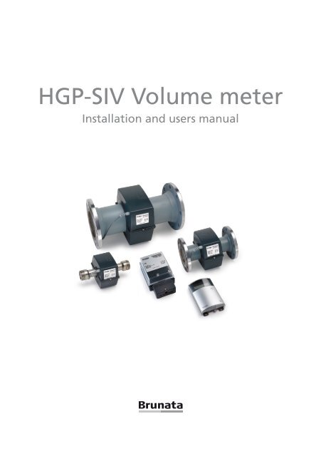
<strong>HGP</strong>-<strong>SIV</strong> <strong>Volume</strong> <strong>meter</strong><br />
Installation and users manual
Please read this before installation<br />
This manual is intended for skilled personal having a formal knowledge to water <strong>meter</strong>s.<br />
The <strong>Brunata</strong> <strong>HGP</strong>-<strong>SIV</strong> volume <strong>meter</strong> must only be used and installed as described in<br />
the manual.<br />
The working data of the <strong>meter</strong> are shown on the label of the <strong>meter</strong>. For further information<br />
we refer to the data sheet.<br />
INPORTANT: Seals and void labels must not be removed or damaged. This will infringe<br />
the warranty of the <strong>meter</strong>.<br />
The <strong>meter</strong> contains of following parts:<br />
1. Flow sensor<br />
2. Flow electronic unit<br />
3. Display unit<br />
4. Signal cable between flow electronics and display unit<br />
5. Installation and users manual<br />
When unpacking the <strong>meter</strong>, please check that all parts are enclosed. The serial<br />
numbers of the flow sensor and the electronic units must be identical, since the parts<br />
are calibrated. The serial number is also programmed into the memory of the <strong>meter</strong>,<br />
please refer to display functions later in this manual.<br />
Versions and ordering code<br />
x: Flow of the <strong>meter</strong><br />
(q p<br />
)in m 3 /h<br />
yy: Connection size:<br />
- 39 = G2B 300 mm<br />
- 40 = DN40 300 mm<br />
- 50 = DN50 270 mm<br />
- 65 = DN65 300 mm<br />
- 80 = DN80 300 mm<br />
- 100 = DN100 360 mm<br />
- 125 = DN125 360 mm<br />
- 150 = DN150 500 mm<br />
z: Menu/display:<br />
174: Standard version with<br />
peak values<br />
178: Tariff <strong>meter</strong><br />
107: Without display<br />
<strong>HGP</strong>-<strong>SIV</strong>x-yy-17z/ABCDE<br />
A: Power supply:<br />
1: 230 VAC<br />
2: 24 VAC<br />
B: Display backlight:<br />
B: with /-: without<br />
C: Programmed for external<br />
<strong>meter</strong>s: 0, 1 or 2<br />
D: Communication module:<br />
M-Bus / LonWorks / RS232 /<br />
- none<br />
E: Nos. of accounting periods:<br />
0 / 6 / 12 / 24<br />
2
Installation<br />
Preparation for installation<br />
Please note that the installation must be done in such a way that it meets the requirements<br />
for internal fitting, distances that have to be respected, etc. Straight pipe sections<br />
before or after the <strong>meter</strong> are not required.<br />
It is recommended that stop valves are fitted before and after the <strong>meter</strong> to<br />
make it easier to remove and reinstall the <strong>meter</strong> if service and verification are<br />
required. To ensure that there are no foreign bodies in the pipe section, it is recommended<br />
that the pipes are flushed through before the <strong>meter</strong> is installed. A<br />
adapter pipe can be used for this purpose. After installation, the valves should<br />
be opened in the order which provides correct flow through the <strong>meter</strong>.<br />
The HG-<strong>meter</strong> has been approved for installation in industrial areas, but it is recommended<br />
that installation close to components that may cause strong electromagnetic<br />
interference is avoided.<br />
Installation of the flow sensor<br />
The flowsensor is installed with the arrow in the flow direction. The flow sensor can be<br />
installed in any direction (vertically, horizontally etc), only the flow sensor must always be<br />
filled with water when running.<br />
Do not insulate the housing of the flow sensor.<br />
Fitting and connection of flow electronic unit, fig. 1<br />
Place the flow electronic unit on an even surface with 3 screws. All connections to the<br />
<strong>meter</strong> must be fitted before mains voltage is connected.<br />
The connection cable from the Flow Sensor is inserted into the socket marked Flow<br />
Head [8] in fig. 1. Note the locking system and how the cable exits the box. To dismantle<br />
the plug, use a small screwdriver to lift the lock. Never shorten nor lengthen the cables<br />
for the flowsensor. If the cable must be rolled up, the dia<strong>meter</strong> of the roll should<br />
at least be 30 cm.<br />
The power supply cable (230 or 24 V) is inserted through the strain relief, which must<br />
be tightened before tightening the terminal connections [1] in fig. 1.<br />
Signal cable to display unit are installed in terminals A1, A2, B1 and B2, [11] in fig. 1.<br />
3
Fitting and connection of display unit, fig 2<br />
Place the display unit on an even surface with 3 screws. All connections to the <strong>meter</strong><br />
must be fitted before mains voltage is connected.<br />
The connecting cable from flow electronic unit is connected to plug M57, see fig 4.<br />
The other cables that need to be connected are led through rubber membrane and<br />
bypass and connected with their respective terminals. Pulse inputs are connected with<br />
terminal [9] and [10], and the remote reading with terminal [5] and [6]. A small screwdriver<br />
or the like can be used to perforate the rubber membrane.<br />
The power supply cable for 230 Volt (possibly 24 Volt) is led through the rubber<br />
membrane and connected with terminal [4] in fig.1, then the strain relief is tightened<br />
moderately. Earth connection is not required.<br />
4
NINGSKLEMMER<br />
Connecting terminals<br />
Flow electronic unit<br />
24 V AC)<br />
ængde<br />
abel<br />
isplayenhed *<br />
ndstikskort *<br />
Fig. 1 Connecting <br />
terminals <strong>HGP</strong> flow electronics<br />
<br />
<br />
No. Indication Connection<br />
1. 230V AC Power (24VAC is possible)<br />
2. Not on <strong>HGP</strong>-<strong>SIV</strong><br />
3. Not on <strong>HGP</strong>-<strong>SIV</strong><br />
4. Not on <strong>HGP</strong>-<strong>SIV</strong><br />
5. Not on <strong>HGP</strong>-<strong>SIV</strong><br />
<br />
<br />
på <strong>HGP</strong>-<strong>SIV</strong><br />
varme rør (rød)<br />
kolde rør (blå)<br />
an være 24VAC)<br />
r datakommunikation, M-Bus, Lon eller RS232<br />
r datakommunikation, M-Bus, Lon eller RS232<br />
pulsudgang, volumen<br />
<br />
<br />
<br />
<br />
6. VOL +/- Pulse out, water volume<br />
7. Not on <strong>HGP</strong>-<strong>SIV</strong><br />
8. FLOW HEAD Stik til flowsensorkabel<br />
9. Not on <strong>HGP</strong>-<strong>SIV</strong><br />
10. Not on <strong>HGP</strong>-<strong>SIV</strong><br />
11. A1,A2,B1,B2 Cable connection to Display unit *<br />
12. HF-plug Connection to insertion module *<br />
* see next page<br />
<br />
<br />
<br />
<br />
<br />
<br />
<br />
<br />
<br />
<br />
5
Ledningsförbindelser och anslutningsklämmer<br />
Displayenhet Display unit<br />
1<br />
13<br />
12<br />
11<br />
10<br />
9<br />
2 3 4<br />
5 6 7 8<br />
NR. MÄRKNING ANSLUTNING Fig. 2 Connecting terminals <strong>HGP</strong>-<strong>SIV</strong> Display Unit<br />
1 FLÖDESSENSOR .. 4-polig, skärmad stickkontakt till flödessensorkabel<br />
PULSVÄRDEN:<br />
2 HIGH No. TEMP. Indication ........... Temperatursensor, Installation varma rör (röd)<br />
3 LOW TEMP............. Temperatursensor, kalla rör (blå)<br />
Mätarens volymp<br />
4 230 VAC.................. 1 FLOWSENSOR Strömspänning 4 legged (Kan vara shielded 24 VAC) plug for flow sensor cable är beroende av<br />
5 A1 B1. ................... 1. Anslutning av datakommunikation, M-Bus, Lon eller RS232 mätarens storlek.<br />
2 HIGH TEMP. Not used on volume <strong>meter</strong><br />
6 A2 B2. ................... 2. Anslutning av datakommunikation, M-Bus, Lon eller RS232 Framgår av<br />
7 - VOL. 3+................... LOW TEMP. Öppen kollektor Not pulsutgång, used on volume volym <strong>meter</strong><br />
typmärket.<br />
8 - ENERGI +. ............ Öppen kollektor pulsutgång, energi<br />
4 230 VAC. Power (24VAC is possible)<br />
Energipuls har<br />
9 - AUX2 +. ................ Extern pulsingång från t ex elmätare<br />
samma värde som<br />
10 - AUX1 5+. ................ A1 B1. Extern pulsingång 1. Installation från t ex of kallvattenmätare<br />
datacommunication, MBus, Lon or RS232 sista siffran i<br />
11 Kontakter 1 & 2 ....... Kontakter för tillkoppling av intern +5 V till AUX- ingångarna<br />
displayen.<br />
12 0 V +5<br />
6<br />
V. ................<br />
A2 B2.<br />
Genemsam<br />
2.<br />
noll<br />
Installation<br />
och +5 V<br />
of<br />
DC<br />
datacommunication,<br />
utgång<br />
MBus or Lon<br />
Har t ex MWh-display<br />
13 M52. ........................ 7 - VOL. +. Stickkontakt Open för datakommunikationskort, collector pulse out, volume M-Bus, pulse Lon eller is shown RS232 on siffror display<br />
efter kommat, ä<br />
8 - ENERGI +. Not used on volume <strong>meter</strong><br />
Pulsutgångar 9 för - AUX2 volym +. och energi Ext. incoming pulse from f.inst. electricity <strong>meter</strong><br />
Pulsutgångens optokopplare strömförsörjs via belastningsmotstånd R, som dimensioneras enl. tabell<br />
10 - AUX1 +. Ext. incoming pulse from f.inst. cold water <strong>meter</strong><br />
11 Switches 1&2 Switches for connection of internal +5V to AUX terminals<br />
Inställning av extern<br />
+Vmax<br />
<br />
5.1<br />
28 V<br />
Motstånd R<br />
strömförsörjning 12 0V +5V. R Common VV<br />
Imax 20 mA<br />
5mA<br />
zero and +5V DC exit<br />
(från mätare: 5 VDC)<br />
Von max 1,5 V<br />
13 M52. Connector for data communication module, MBus, Lon<br />
+V R för I=5 mA<br />
ton=toff=140 ms är standardinställning<br />
Pulsperiod or T= RS232<br />
ton + toff = 280 ms.<br />
5 700 <br />
+<br />
+Voff<br />
10 1,7 k<br />
15 Values 2,7 of k pulse<br />
20 3,7 k<br />
Von toff ton<br />
24 <strong>Volume</strong> GND (0V)<br />
4,5<br />
pulse<br />
k<br />
HGG-<strong>SIV</strong>-<strong>meter</strong> pulse value depends on Fig. size 2 Anslutningsexempel of the <strong>meter</strong>. Please för consult<br />
Pulsperioder från 40 till 1560 ms kan förekomma<br />
volympulsutgång med intern 5 V<br />
28 the type<br />
5,3<br />
sign.<br />
k<br />
försörjning<br />
6
af forbindelsesledning mellem flowelektronik og displayenhed<br />
ation skal der være slukket for netspændingen til såvel flowelektronikken som displayenheden.<br />
egel er <strong>HGP</strong>-<strong>SIV</strong> Connecting måleren cable leveret som en komplet enhed,<br />
modulet <strong>HGP</strong>-HF-SD-conv. monteret i <strong>HGP</strong> flowmåleren.<br />
konverterer<br />
Before<br />
hurtigpuls<br />
installation,<br />
signalet<br />
the<br />
fra flowmåleren<br />
mains voltage<br />
til et<br />
to<br />
hurtigder<br />
kan anvendes electronics af displayenhed.<br />
as well as to the display unit must be<br />
the flow<br />
turned off.<br />
odulet leveret<br />
If the<br />
som<br />
<strong>HGP</strong><br />
løst<br />
<strong>SIV</strong><br />
tilbehør<br />
<strong>meter</strong><br />
(se<br />
is delivered<br />
fig 3) gøres<br />
as<br />
følgende:<br />
a complete unit<br />
t monteres<br />
the<br />
på<br />
insertion<br />
stikket i måleren,<br />
module<br />
se<br />
is already<br />
tegning.<br />
installed<br />
Sørg for,<br />
in<br />
at<br />
the<br />
alle<br />
<strong>HGP</strong><br />
ads i stikket. Den nye skillebøjle monteres i kassen i stedet<br />
flow <strong>meter</strong>. The insertion module transforms the<br />
terende, og det 2-polede stik monteres på M12 i måleren.<br />
fast pulse signal from the flow <strong>meter</strong> into a fast<br />
pulse signal usable for the display unit.<br />
Fig. <br />
3 Insertion module with<br />
division clamp<br />
If the insertion module comes as a separate item<br />
the following guidelines must be observed: The insertion module is mounted on<br />
the connector M52, see drawing. Pay attention when mounting the insertion module<br />
and make sure that all pins are placed correctly in the connector. The enclosed<br />
division clamp is installed instead of the existing one and finally the 2-poled<br />
connector is mounted.<br />
<strong>HGP</strong> electronics<br />
M57<br />
1<br />
n mellem <strong>HGP</strong> flowelektronik og displayenhed sker ved anvendelse af det medfølgende 4-leder<br />
rbindes i flowelektronikkens terminaler A1, A2, B1 og B2 som vist i fig 4. Det hvide stik monteres<br />
i displayenheden, og ledning og gummimembran <strong>HGP</strong> HP-SD Conv. trykkes på plads i aflastningen.<br />
M57 USB<br />
<br />
<br />
M12<br />
inaler Ledningsfarve, tegning Ledningsfarve<br />
1<br />
M57-stik (<strong>HGP</strong>-<strong>SIV</strong>) Signal<br />
A1 A2<br />
B1 B2<br />
Rød Rød 5 +5V<br />
Sort Sort 1 GND<br />
Gul Gul 4 Data<br />
Grøn Grøn 2 Clock<br />
ing af måleren<br />
<strong>HGP</strong> HP-SD Conv.<br />
g tilsluttes til begge enheder, og måleren vil straks begynde at registrere, hvis 1 der Blacker vandflow.<br />
Green<br />
er ikke skade, såfremt der ikke er vand på anlægget, men kan, hvis flowsensoren ikke er helt<br />
Yellow<br />
gistrere et tilfældigt flow.<br />
1<br />
Red<br />
Red<br />
M12<br />
Black<br />
odulet er der i øverste højre hjørne to lysdioder til indikation af signal. Grøn diode indikerer mod-<br />
Yellow<br />
nal fra <strong>HGP</strong>, og når der er flow,<br />
Green<br />
A1 blinker A2 dioden. Hvis den ikke blinker, kan det skyldes manglen-<br />
B1 B2<br />
at stikket er faldet af eller er vendt forkert.<br />
M57<br />
dikerer at der sendes data til Beregningsenheden. Den blinker for hvert 1,6 sekund, og hvis den<br />
undersøges det om stikket på M57 er korrekt monteret, samt forbindelserne A1, A2, B1, B2 er i<br />
ema og skitser.<br />
7<br />
er tilsluttet, og der løber vand gennem flowsensoren blinker en firkant i display i takt med vand-
Connection between the <strong>HGP</strong> flow electronics and the display unit takes place using<br />
the enclosed 4-poled cable which is connected in the terminals A1, A2, B1 and B2 of<br />
the flow electronics as shown on the drawing. The white connector is mounted on connector<br />
M57 of the display unit and the cable and rubber membrane are pressed to fit<br />
at the strain relief.<br />
<strong>HGP</strong><br />
terminals<br />
Wire colour<br />
M57 pin no.<br />
(<strong>HGP</strong>-<strong>SIV</strong>)<br />
Signal<br />
A1 Red 5 +5V<br />
A2 Black 1 GND<br />
B1 Yellow 4 Data<br />
B2 Green 2 Clock<br />
Putting the <strong>meter</strong> into operation<br />
Mains voltage is connected to both units and the <strong>meter</strong>s starts registration at once. The<br />
<strong>meter</strong> does not sustain damage if there is no water in the system, but it may register a<br />
random flow in case the flow sensor is not completely filled with water.<br />
In the upper right corner of the PCB are two lightemitting diodes (LEDs) for indication<br />
of signals. The green LED indicates received flow signal from <strong>HGP</strong> an when you have<br />
flow the LED flashes. If it does not flash it could be due to lack of flow, the connector<br />
has fallen out or has been reversed.<br />
The red LED indicates that data is being sent to the calculation unit. It flashes every 1.6<br />
seconds and if it does not flash it is advised to check if the connector M57 is installed<br />
correctly and that the connections A1, A2, B1 and B2 are working correctly. See table<br />
and drawings.<br />
When the <strong>meter</strong> is connected and water is running through the flow sensor a square in<br />
the display is flashing concurrently with the water pulses.<br />
Attention: The <strong>meter</strong>’s counter cannot be zeroed after delivery.<br />
8
Specification of Output Pulses:<br />
Pulse output for volume and energy<br />
The open collector pulse out is power supplied with load resistance R, whic<br />
The open collector pulse out is power supplied with load resistance R, which is dimensioned<br />
according to table<br />
table below.<br />
below.<br />
Setting of external + V − 5.1 V<br />
voltage supply R =<br />
5mA<br />
(from <strong>meter</strong>: 5 VDC) <br />
+V R for I=5 mA <br />
5 700 Ω Ω<br />
<br />
10 1,7 k Ω Ω <br />
15 2,7 k Ω Ω <br />
<br />
20 3,7 k Ω Ω<br />
Ω<br />
24 4,5 k Ω<br />
lied with load resistance R, which is dimensioned Ω according to<br />
28 5,3 k Ω<br />
<br />
<br />
<br />
<br />
<br />
<br />
<br />
<br />
<br />
<br />
<br />
<br />
<br />
V5.1<br />
<br />
<br />
<br />
<br />
<br />
<br />
<br />
Insertion og communication module<br />
A communication module RS262, M-Bus or LON is plugged into the display<br />
nected to the terminals A1+B1 and A2+B2, [5] and [6] in fig 2.<br />
+<br />
Connection of external <strong>meter</strong>s with pulse outlet<br />
NB only valid for <strong>meter</strong>s, which has been programmed for connection<br />
The <strong>meter</strong> accepts active as well as passive signal source. The most comm<br />
<br />
which are connected to the terminals AUX 1 or AUX 2 and the switch in pos<br />
Fig. 5 Example of connection for volume pulse output with internal 5V<br />
fig. 6. <br />
<br />
Insertion og<br />
Connection<br />
communication<br />
of <strong>meter</strong>s<br />
module<br />
with active signal source is done as illustrated in pictu<br />
position OFF.<br />
A communication module RS262, M-Bus or LON is plugged into the display unit, and<br />
the signal cable Each is connected of the 2 input to the AUX1 terminals and A1+B1 AUX2 and can A2+B2. be set separately. Please note th<br />
r LON is plugged into the display unit, and the signal cable is con-<br />
Connection of external <strong>meter</strong>s with pulse outlet<br />
, [5] and [6] in fig 2.<br />
(only valid for <strong>meter</strong>s, which has been programmed for connection of external <strong>meter</strong>s)<br />
The <strong>meter</strong> accepts active as well as passive signal source. The most common is passive<br />
<br />
signal source, which are connected to the terminals AUX 1 or AUX 2 and the switch in<br />
pulse outlet<br />
position ON as shown in picture B, fig. 6.<br />
n programmed for connection of external <strong>meter</strong>s.<br />
e signal source. Connection The of most <strong>meter</strong>s common with active is signal passive source signal is done source, as illustrated in picture B, fig. 6 <br />
with the switch in position OFF.<br />
1 or AUX 2 and the switch in position ON as shown in picture B,<br />
<br />
Each of the 2 input AUX1 and AUX2 can be set separately. Please note the polarity, <br />
<br />
see fig. 6.<br />
<br />
<br />
urce is done as illustrated in picture B, fig. 6 with the switch in<br />
<br />
e set separately. Please note the polarity, see fig. 6.<br />
9
Connection of <strong>meter</strong>s with active signal source is done as illustrated in picture B, fig. 6 with the switch in<br />
position OFF.<br />
Each of the 2 input AUX1 and AUX2 can be set separately. Please note the polarity, see fig. 6.<br />
<br />
+V on<br />
<br />
GND (0V)<br />
<br />
<br />
<br />
Input-specifikation<br />
<br />
<br />
+ -<br />
Minus<br />
Von<br />
V<br />
>2,5 V<br />
on<br />
>2,5 V<br />
Voff 50 ms<br />
<br />
A. Aktiv signalkälla B. Passiv signalkälla<br />
<br />
Kontakter 1 & 2: OFF<br />
Kontakter 1 & 2: ON Fig. 3 Anslutning av externa mätare<br />
Galvaniskt A. Active åtskilt signal source B. Potential-free Ej galvaniskt switch-connection<br />
åtskilt<br />
<br />
Switch 1 & 2: OFF<br />
Switch 1 & 2: ON<br />
Galvanic separated NOT galvanic separated<br />
<br />
Sealing<br />
Vesterlundvej 14 DK-2730 Herlev Denmark Tel:+45 7777 7000 Fax: +45 7777 7001<br />
E-mail: brunata@brunata.com Internet: www.brunata.com<br />
<br />
V off t on t off<br />
Fig. 6 Connection of external <strong>meter</strong>s<br />
The flow electronic unit is from the factory sealed through the transparent lid and<br />
the screw allowing access to the terminals. After mounting and connecting the unit the<br />
black lid is screwed on and the unit can be sealed using sealing wire and a seal.<br />
The display unit is sealed electronically when delivered. The box is closed and sealed<br />
with <strong>Brunata</strong> special seal made of plastic, which is pushed into the narrow hole on the<br />
bottom of the box. The seal can be removed with a screwdriver. The broken piece of<br />
the seal is to be pushed into the box with the screwdriver and hereafter the box can be<br />
opened. Alternatively the box can be closed with the enclosed screw and sealed with<br />
thread through the hole next to the screw for the lid.<br />
<br />
energi-IV-BV-DK4/08.05.2006 Copyright © <strong>Brunata</strong> a/s 2006 Sida 4<br />
<strong>Brunata</strong> a/s • Kapplöpningsg. 14 • Box 5066 • S-250 05 Helsingborg • Sverige • Tel:+46 (0)42-13 37 59<br />
Fax: +46 (0)42-18 74 65 • E-mail: brunata@brunata.se • Internet: www.brunata.se<br />
10
Operating manual<br />
perating the <strong>meter</strong><br />
he menu of The the <strong>meter</strong> menu is of structured the <strong>meter</strong> in is 3-4 structured menus, and in 3-4 you navigate menus, and from you one navigate display to from another one using display the<br />
ush button on to another display using unit. the The push following button illustration the shows display the unit. standard The following menu structure illustration a <strong>Brunata</strong> shows<br />
G volume <strong>meter</strong> the standard menu structure on a <strong>Brunata</strong> HG volume <strong>meter</strong><br />
3)<br />
<br />
<br />
<br />
<br />
<br />
<br />
<br />
1)<br />
1)<br />
4)<br />
<br />
<br />
<br />
<br />
<br />
<br />
<br />
<br />
<br />
<br />
<br />
<br />
<br />
<br />
2)<br />
<br />
<br />
<br />
<br />
<br />
<br />
1)<br />
1)<br />
2)<br />
<br />
<br />
<br />
<br />
<br />
<br />
<br />
<br />
<br />
<br />
<br />
<br />
<br />
<br />
<br />
<br />
<br />
<br />
<br />
<br />
2)<br />
4)<br />
<br />
<br />
<br />
<br />
<br />
<br />
<br />
<br />
<br />
<br />
<br />
<br />
<br />
<br />
<br />
<br />
<br />
<br />
<br />
<br />
Remarks<br />
1) Only in <strong>meter</strong> programmed for pulse input from external <strong>meter</strong>s<br />
emarks 2) Only in <strong>meter</strong> type -178 programmed for tariff functions<br />
1) Only 3) in <strong>meter</strong> File menu programmed is included for pulse only if input <strong>meter</strong> from is external programmed <strong>meter</strong>s for storage of data<br />
2) Only 4) in <strong>meter</strong> Only in programmed <strong>meter</strong> programmed for remote for reading remote reading<br />
3) Only in <strong>meter</strong> type -178 programmed for tariff functions<br />
4) File menu is included only if <strong>meter</strong> is programmed for storage of data<br />
11
Operating the <strong>meter</strong><br />
Introduction<br />
The <strong>meter</strong> is operated using the push button on the<br />
front of the electronic unit. Pressing once you step<br />
down in the actual menu you are in. By pressing<br />
the button in a few seconds, you can step from one<br />
menu to the next.<br />
Except for the User Menu the No. of the actual<br />
menu is shown in the display.<br />
Push<br />
button<br />
In case the <strong>meter</strong> is delivered with Storage Menu, the <strong>meter</strong> read itself and stores data<br />
as default on the 1st each month or at an optional selected date, see the order confirmation<br />
or consult the Service Menu. Until the first date occur the menu will be empty,<br />
displaying _ _._ _._ _._ _<br />
Peak values are registered in the period from the 1st in actual month. Values are reset<br />
(zeroed) at each turn of the month.<br />
With <strong>meter</strong>s supplied with module for remote reading, the user himself in the User<br />
Menu can check the time where the <strong>meter</strong> has been read. The communication address<br />
of the <strong>meter</strong> appears in the Service Menu.<br />
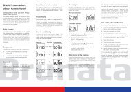
Normal operation – User menu<br />
By pushing the button once you will see the accumulated volume in the display (m3).<br />
If the <strong>meter</strong> is sup-plied with display light, pushing the button activates this function.<br />
Pushing once again the display will change to different pictures (see illustration).<br />
When the pushbutton has not been activated for approx. 1 minute the display will automatically<br />
return to accumulated volume (m3) and the light (if delivered) will turn off.<br />
Advanced operation – all menus<br />
When holding down the button for a short while, the display will change from one<br />
menu to the next. The menu reached is indicated in the upper part of the display (except<br />
Menu 1). The order of the menus is there-fore: [none], 2 ,3 and 4.<br />
When you reach the needed menu, release the pushbutton and the menu is now activated.<br />
By pushing once the different display pictures will show (as mentioned above).<br />
Display pictures containing peak flow will automatically alternate between peak value<br />
and date/time of regis-tration.<br />
For <strong>meter</strong>s delivered with tariff function the consumption is displayed in Tariff volume<br />
$, according to the criteria’s selected. The selected criteria can be seen in the service<br />
menu.<br />
12
Stored data menu<br />
If the <strong>meter</strong> is programmed for storage of data, in menu 3 you find data stored for 24<br />
accounting periods, and you can step through the different periods by pressing the button<br />
quickly twice. The date and time when the data has been stored is shown as first<br />
display in each accounting period. The first period showed are the most recent. You<br />
can step through the information stored by pressing the button once. By pressing the<br />
button quickly twice you step to the next period, and after having reached the latest<br />
reading (register 24) you will again see the most recent readings.<br />
Information and error codes<br />
Should an error occur in the <strong>meter</strong>, the display will be flashing ”Error” followed by one<br />
of following error codes:<br />
1. Interruption of power supply. The information is logged in the error register, and<br />
not showed in the display.<br />
2. Not used for volume <strong>meter</strong>s<br />
3. Not used for volume <strong>meter</strong>s<br />
4. Not used for volume <strong>meter</strong>s<br />
5. Low voltage in back-up battery [V Bat<br />
< V Treshold<br />
].<br />
6. Short circuit of magnet coil in the flowsensor [Coil current exceeds limit value for<br />
more than 8 sec].<br />
7. Error in the programming of the <strong>meter</strong> [RAM not initialised].<br />
8. Not used for volume <strong>meter</strong>s<br />
9. Wrong time/date in the <strong>meter</strong> (see Service Menu) – clock must be adjusted.<br />
In case of error the <strong>meter</strong> automatically will registers when (date and time) the error has<br />
occurred and also the accumulated error time.<br />
When two errors occur at the same time, both codes are shown. Example: Error code 71<br />
indicates error in the programming, and interruption of power supply.<br />
At code no. 6 the error message is shown in the display as long as the error occurs. The<br />
hours with error are registered in the register for Accumulated error hours. If the power<br />
supply is terminated, the time without power is registered in the error hours register.<br />
At code 5, 7 and 9 the error message is shown in the display as long as the error occurs,<br />
but will not be reg-istered in the register for Accumulated error hours.<br />
By interruption of the power supply the display will be blank. When the power is reestablished<br />
the <strong>meter</strong> will immediately start registering again.<br />
By error code 5, low battery-supply, the <strong>meter</strong> will continue the normal registration as<br />
long as it is powered but the battery must be replaced as soon as possible.<br />
13
By error code 9, the <strong>meter</strong> has been without power supply, and battery-supply. The <strong>meter</strong><br />
will continue the normal registration when power is restored, but the internal clock<br />
should be adjusted. Please contact nears <strong>Brunata</strong> service department.<br />
In case of questions, you are always welcome to contact your local <strong>Brunata</strong> service<br />
department, or send an e-mail to service@brunata.dk.<br />
14
Notes<br />
15
Notes<br />
<strong>Brunata</strong> a/s · Vesterlundvej 14 · DK-2730 Herlev · tel. +45 77 77 70 00<br />
fax +45 77 77 70 01 · www.brunata.com · brunata@brunata.com<br />
UK-QB 10.1487/30.05.2008<br />
16