Air Traffic Management Concept Baseline Definition - The Boeing ...
Air Traffic Management Concept Baseline Definition - The Boeing ...
Air Traffic Management Concept Baseline Definition - The Boeing ...

Create successful ePaper yourself
Turn your PDF publications into a flip-book with our unique Google optimized e-Paper software.
• Sector-level flow planning<br />
Each level has a certain planning time horizon and range of possible planning actions, as<br />
will be discussed in detail in Section 3.2.4 and 3.2.5.<br />
3.2.3 Levels of Plan Execution in the System<br />
Flight and flow plans in the system are executed through a number of functions, the<br />
primary ones being:<br />
• <strong>Air</strong>craft guidance and navigation<br />
• Separation assurance<br />
• <strong>Air</strong>craft on-board collision avoidance<br />
<strong>The</strong> execution functions are discussed in detail in 3.2.4 and 6.<br />
3.2.4 Functional Structure<br />
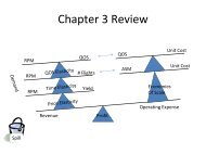
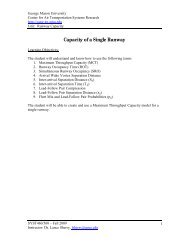
Figure 3.2 shows the functional structure of the air traffic management system in terms of<br />
functions directly affecting the process that links real-time traffic demand with actual flight<br />
through NAS airspace.<br />
Weather<br />
Flight<br />
Planning<br />
Filed<br />
Flight<br />
Plans<br />
Flight<br />
Schedule<br />
Schedule of<br />
Capacities<br />
National<br />
Flow<br />
Planning<br />
hrs - day<br />
Planning<br />
Approved<br />
Flight<br />
Plans Facility<br />
Flow<br />
Planning<br />
hrs<br />
Planned<br />
Flow<br />
Rates<br />
Desired<br />
Sector<br />
Loads<br />
Sector<br />
<strong>Traffic</strong><br />
Planning<br />
5-20 min<br />
Clearance<br />
Requests<br />
Approved<br />
Handoffs<br />
Negotiate<br />
Handoffs<br />
Sector<br />
<strong>Traffic</strong><br />
Control<br />
5 min<br />
Clearance<br />
Requests<br />
Execution<br />
AOC<br />
Vectors<br />
<strong>Air</strong>craft <strong>Air</strong>craft State<br />
Guidance and<br />
Clearances Navigation<br />
< 5 min<br />
<strong>Traffic</strong><br />
Sensor<br />
<strong>Air</strong>line CFMU TMU D-side R-side<br />
Real State<br />
Plan/Intent<br />
Measurement<br />
Requests<br />
AC State<br />
Sensor<br />
Pilot<br />
Other <strong>Air</strong>craft<br />
States<br />
Efficiency<br />
Throughput<br />
Safety<br />
Increasing Criticality Level<br />
Figure 3.2 <strong>Air</strong> <strong>Traffic</strong> <strong>Management</strong> System Functional Structure<br />
<strong>The</strong> diagram in Figure 3.2 illustrates the processes and information flow that make up the<br />
traffic planning and separation assurance functions of the system. Figure 3.2 is only one of<br />
many possible cross sections through a very large and complex system and hides a<br />
considerable amount of detail, but is conceptually valid and useful to serve this discussion<br />
of system safety, capacity and efficiency . It is also important to note that Figure 3.2 is an<br />
29