Air Traffic Management Concept Baseline Definition - The Boeing ...
Air Traffic Management Concept Baseline Definition - The Boeing ... Air Traffic Management Concept Baseline Definition - The Boeing ...
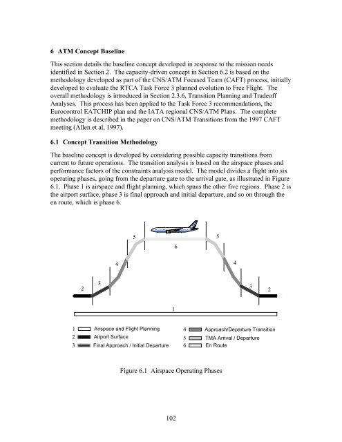
6 ATM Concept Baseline This section details the baseline concept developed in response to the mission needs identified in Section 2. The capacity-driven concept in Section 6.2 is based on the methodology developed as part of the CNS/ATM Focused Team (CAFT) process, initially developed to evaluate the RTCA Task Force 3 planned evolution to Free Flight. The overall methodology is introduced in Section 2.3.6, Transition Planning and Tradeoff Analyses. This process has been applied to the Task Force 3 recommendations, the Eurocontrol EATCHIP plan and the IATA regional CNS/ATM Plans. The complete methodology is described in the paper on CNS/ATM Transitions from the 1997 CAFT meeting (Allen et al, 1997). 6.1 Concept Transition Methodology The baseline concept is developed by considering possible capacity transitions from current to future operations. The transition analysis is based on the airspace phases and performance factors of the constraints analysis model. The model divides a flight into six operating phases, going from the departure gate to the arrival gate, as illustrated in Figure 6.1. Phase 1 is airspace and flight planning, which spans the other five regions. Phase 2 is the airport surface, phase 3 is final approach and initial departure, and so on through the en route, which is phase 6. 5 6 5 4 4 3 2 3 2 1 1 Airspace and Flight Planning 4 Approach/Departure Transition 2 Airport Surface 5 TMA Arrival / Departure 3 Final Approach / Initial Departure 6 En Route Figure 6.1 Airspace Operating Phases 102
Constraints modeling can be performed for system safety, capacity, efficiency or productivity measures. The methodology allows examination of the technical and human performance factors which potentially affect the airspace region. The final approach and initial departure phases include the runway and refer to a phase in which air traffic control interventions are minimal due to the nature of the aircraft operation. The approach transition phase is operated differently depending on available technology and traffic density. In busy airports this is generally where air traffic controllers vector aircraft to merge traffic into properly spaced streams for final approach and landing, while in low density operations it might be a single waypoint transition to the next region. The Terminal Maneuvering Area (TMA) arrival/departure phase is generally operated through published SID and STAR procedures. The en route phase encompasses the remainder of the flight, including published transitions from SID to cruise and from cruise to STAR. En route operations vary greatly by location, anywhere from oceanic procedural control to dense traffic in radar controlled airspace. The differences in operation can be characterized by levels of performance for the CNS components, as well as by air traffic control automation support, topography, traffic flow patterns, airspace availability and so on. En Route TMA Arrival/Departure Planning AIRSIDE CAPACITY/EFFICIENCY FACTORS Approach Transition Airport Surface Gate Final Approach/ Initial Departure Taxiway Apron Final Approach Initial Departure CONDITION: LOCATION: Figure 6.2 Capacity and Efficiency as a Function of Airspace Operating Phases Using the six operating phases above, Figure 6.2 provides a graphical illustration of how the capacity and efficiency of operations are aggregated across the various operating phases. Overall system capacity and efficiency are complex functions of the type of 103
- Page 63 and 64: arbitrating wherever intents confli
- Page 65 and 66: aircraft-to-aircraft separation res
- Page 67 and 68: 5 Available and Emerging Technology
- Page 69 and 70: function of all the ICPs of element
- Page 71 and 72: A key concept in the definition of
- Page 73 and 74: contrast, the older radars have azi
- Page 75 and 76: Broadcast (ADS-B), V6.0). Individua
- Page 77 and 78: is needed to develop cockpit displa
- Page 79 and 80: ATC Voice Procedures Waypoint Repor
- Page 81 and 82: CPC = Controller Pilot Communicatio
- Page 83 and 84: TWDL = Two-Way Data Link CPDLC = Co
- Page 85 and 86: the ATN ADS specification. This wil
- Page 87 and 88: The airlines and the FAA have recen
- Page 89 and 90: menu associated with the airport of
- Page 91 and 92: 8.0 NM 4.0 NM POPP PLMN 14.0 NM 30.
- Page 93 and 94: The near future will probably see a
- Page 95 and 96: ASR/SSR Radar Terminal Automation S
- Page 97 and 98: ASR/SSR Radar Mosaic Based (Host) T
- Page 99 and 100: Another group of users which can be
- Page 101 and 102: and human factor elements in all fo
- Page 103 and 104: ASOS AWOS TDWR NEXRAD Surface Upper
- Page 105 and 106: sets as legitimate atmospheric data
- Page 107 and 108: AWIPS/WFO- Advanced WARP Analysis P
- Page 109 and 110: longer-term domestic and internatio
- Page 111 and 112: example, the ceiling and visibility
- Page 113: WARP TWIP ITWS CWIN Information Dis
- Page 117 and 118: Figure 6.4 shows a template for ill
- Page 119 and 120: National Level. Improved Traffic Fl
- Page 121 and 122: of flight plan management and mediu
- Page 123 and 124: The component of the spacing buffer
- Page 125 and 126: 6.2.5 NAS Surface Figure 6.9 shows
- Page 127 and 128: trades involved in this step will r
- Page 129 and 130: exchange of traffic rights.” (Don
- Page 131 and 132: above, the agency’s organizationa
- Page 133 and 134: concepts under consideration for th
- Page 135 and 136: 1.2.4. A coordinated traffic flow p
- Page 137 and 138: Concepts Requirements Trades Evalua
- Page 139 and 140: 2. Intent: The research area identi
- Page 141 and 142: Acknowledgments The Boeing team wor
- Page 143 and 144: Eurocontrol (1996), Meeting Europe
- Page 145 and 146: Schadt, J and Rockel, B. (1996),
- Page 147 and 148: Warren, A.W. (1994), “A New Metho
- Page 149 and 150: Table A-1 Communication Application
- Page 151 and 152: Table A-3 Communication Media Techn
- Page 153 and 154: A.2 Navigation The navigation techn
- Page 155 and 156: Table A-5 Navigation Processors Pro
- Page 157 and 158: standardized as VDL Mode-4. Both sy
- Page 159 and 160: Table A-6 Surveillance Inventory Su
- Page 161 and 162: Appendix B. Global Scenario Issue T
- Page 163 and 164: Issue # 2: Some Limitations of Futu
6 ATM <strong>Concept</strong> <strong>Baseline</strong><br />
This section details the baseline concept developed in response to the mission needs<br />
identified in Section 2. <strong>The</strong> capacity-driven concept in Section 6.2 is based on the<br />
methodology developed as part of the CNS/ATM Focused Team (CAFT) process, initially<br />
developed to evaluate the RTCA Task Force 3 planned evolution to Free Flight. <strong>The</strong><br />
overall methodology is introduced in Section 2.3.6, Transition Planning and Tradeoff<br />
Analyses. This process has been applied to the Task Force 3 recommendations, the<br />
Eurocontrol EATCHIP plan and the IATA regional CNS/ATM Plans. <strong>The</strong> complete<br />
methodology is described in the paper on CNS/ATM Transitions from the 1997 CAFT<br />
meeting (Allen et al, 1997).<br />
6.1 <strong>Concept</strong> Transition Methodology<br />
<strong>The</strong> baseline concept is developed by considering possible capacity transitions from<br />
current to future operations. <strong>The</strong> transition analysis is based on the airspace phases and<br />
performance factors of the constraints analysis model. <strong>The</strong> model divides a flight into six<br />
operating phases, going from the departure gate to the arrival gate, as illustrated in Figure<br />
6.1. Phase 1 is airspace and flight planning, which spans the other five regions. Phase 2 is<br />
the airport surface, phase 3 is final approach and initial departure, and so on through the<br />
en route, which is phase 6.<br />
5<br />
6<br />
5<br />
4<br />
4<br />
3<br />
2 3<br />
2<br />
1<br />
1 <strong>Air</strong>space and Flight Planning 4 Approach/Departure Transition<br />
2 <strong>Air</strong>port Surface<br />
5 TMA Arrival / Departure<br />
3 Final Approach / Initial Departure 6 En Route<br />
Figure 6.1 <strong>Air</strong>space Operating Phases<br />
102


