Diagnostics and testing of rotating electrical machines - DNV Kema
Diagnostics and testing of rotating electrical machines - DNV Kema
Diagnostics and testing of rotating electrical machines - DNV Kema

You also want an ePaper? Increase the reach of your titles
YUMPU automatically turns print PDFs into web optimized ePapers that Google loves.
<strong>DNV</strong> KEMA sERVING THE ENERGy INDusTRy<br />
Non-destructive <strong>testing</strong> & plant diagnostics<br />
<strong>Diagnostics</strong> <strong>and</strong> <strong>testing</strong> <strong>of</strong><br />
<strong>rotating</strong> <strong>electrical</strong> <strong>machines</strong><br />
PREPARE<br />
AND<br />
PREVENT
02<br />
ENERGY<br />
Non-destructive <strong>testing</strong> & plant diagnostics<br />
PREPARE AND PREVENT<br />
<strong>Diagnostics</strong> <strong>and</strong> <strong>testing</strong> <strong>of</strong> <strong>rotating</strong> <strong>electrical</strong> <strong>machines</strong><br />
Rotating <strong>machines</strong> are <strong>of</strong> vital importance to many business processes. As the dem<strong>and</strong> for energy continues to grow,<br />
operational continuity is increasingly important. The failure <strong>of</strong> <strong>rotating</strong> machinery used in energy production, waste<br />
processing <strong>and</strong> other industrial processes not only has financial <strong>and</strong> operational consequences for the owners, but in<br />
many cases also has implications for the community at large. <strong>DNV</strong> KEMA Energy & Sustainability possesses enormous<br />
specialist expertise, which is made available to help clients keep their vital processes running.<br />
Responsible use <strong>of</strong> aging <strong>machines</strong><br />
Being vital to many industrial processes, <strong>rotating</strong> <strong>machines</strong> are<br />
designed to operate reliably for years on end. However, as time<br />
goes by, attention inevitably is focused on the condition <strong>of</strong> aging<br />
<strong>machines</strong> <strong>and</strong> how much longer they can be expected to go on<br />
providing problem-free service. With a wide range <strong>of</strong> diagnostic<br />
techniques at its disposal, <strong>DNV</strong> KEMA can help you minimize<br />
the operating <strong>and</strong> financial cost <strong>of</strong> finding answers. Our advice<br />
will enable you to identify the most cost-effective <strong>and</strong> responsible<br />
maintenance strategy <strong>and</strong> operational approach, now <strong>and</strong> in the<br />
future.<br />
The need to manage costs makes it sensible to consider whether<br />
<strong>rotating</strong> <strong>machines</strong> can remain in service longer without undue<br />
outage risk or excessive expenditure on maintenance.<br />
After all, the serviceability <strong>of</strong> a component depends not only on<br />
its age, but also on the way it is operated <strong>and</strong> maintained, <strong>and</strong><br />
what has happened to it in the past.<br />
<strong>DNV</strong> KEMA can provide answers to the questions that you are<br />
liable to face, such as:<br />
■■<br />
What condition is our machinery actually in<br />
■■<br />
Can we make even better use <strong>of</strong> our <strong>rotating</strong> machinery<br />
■■<br />
How much longer can our machinery remain in service<br />
■■<br />
Can we reasonably postpone capital expenditure<br />
■■<br />
Is it worthwhile repairing our machinery, or should we replace it<br />
■■<br />
How big a risk would we be taking if we took no action yet<br />
■■<br />
What was the cause <strong>of</strong> the damage our machine has<br />
unexpectedly suffered, <strong>and</strong> who is responsible
Non-destructive <strong>testing</strong> & plant diagnostics<br />
ENERGY 03<br />
It is not always easy to give answers to such questions. A <strong>rotating</strong><br />
machine is, after all, merely part <strong>of</strong> a large <strong>and</strong> complex process.<br />
It is expected to simply go on doing its job, <strong>and</strong> analyzing its<br />
condition is not part <strong>of</strong> your core activities. Although most<br />
companies that operate <strong>rotating</strong> machinery are reasonably<br />
knowledgeable about the working <strong>of</strong> their assets, precise<br />
condition determination <strong>and</strong> residual service life assessment are<br />
the work <strong>of</strong> specialists. Specialists for whom the <strong>testing</strong> <strong>and</strong><br />
inspection <strong>of</strong> machinery are everyday tasks <strong>and</strong> who have an<br />
armory <strong>of</strong> diagnostic techniques at their disposal. Specialists<br />
who bring many years <strong>of</strong> experience to the diagnosis <strong>of</strong> your<br />
installation <strong>and</strong> who are able to consider your machinery from<br />
an impartial perspective.<br />
Specialists that <strong>DNV</strong> KEMA can deploy on your behalf. At <strong>DNV</strong><br />
KEMA, we have the knowledge, the methodological expertise<br />
<strong>and</strong> tools to provide you with the backup <strong>and</strong> support that you<br />
need to maximize operational efficiency <strong>and</strong> reliability. Now <strong>and</strong><br />
in the future.<br />
Design<br />
<strong>DNV</strong> KEMA can help you to obtain exactly the right machine for<br />
your company or process. A supplier is responsible for delivering<br />
products <strong>and</strong> services that meet your specified requirements.<br />
It is therefore important that you specify your requirements<br />
accurately. Well-formulated <strong>DNV</strong> KEMA (S-)specifications<br />
provide a basis for the assessment <strong>of</strong> a supplier’s design. Good<br />
specifications are the starting point for a sound design, which<br />
is essential for obtaining a machine that performs optimally<br />
throughout its service life.<br />
Manufacture<br />
During manufacture, a number <strong>of</strong> topics are <strong>of</strong> particular<br />
importance: the selection <strong>of</strong> materials <strong>and</strong> the actual process<br />
<strong>of</strong> manufacture <strong>and</strong> the mechanisms with which you, as the<br />
(prospective) owner, can obtain assurance regarding the<br />
quality <strong>of</strong> the finished machine. <strong>DNV</strong> KEMA can support you<br />
during manufacture by providing ongoing quality control, by<br />
witnessing the acceptance tests at the factory <strong>and</strong> on site, <strong>and</strong> by<br />
supervising the commissioning.
04<br />
ENERGY<br />
Non-destructive <strong>testing</strong> & plant diagnostics<br />
■■<br />
Quality control: checking the manufacturing process by<br />
inspection <strong>and</strong> <strong>testing</strong>. Various components are tested during<br />
manufacture. The manufacturer’s progress, quality assurance<br />
measures <strong>and</strong> results are also assessed.<br />
■■<br />
Tests (FAT <strong>and</strong> SAT): <strong>DNV</strong> KEMA performs its own tests or<br />
witnesses <strong>testing</strong> by others to check conformance to the design<br />
specifications. During factory acceptance <strong>testing</strong> (FAT), type<br />
tests <strong>and</strong> routine tests are performed to verify that the <strong>rotating</strong><br />
machine has been built in accordance with the specifications.<br />
During site acceptance <strong>testing</strong> (SAT), the quality <strong>of</strong> the<br />
delivered installation is checked to ascertain whether it fullfils<br />
the applicable requirements.<br />
■■<br />
Commissioning: once all the separate components have been<br />
installed <strong>and</strong> tested, <strong>DNV</strong> KEMA will witness <strong>and</strong> assess <strong>testing</strong><br />
<strong>of</strong> the complete installation under various normal <strong>and</strong>/or<br />
extreme operating scenarios, defined by consultation.<br />
From design to decommissioning<br />
The life cycle <strong>of</strong> any machine may be divided into the following phases:<br />
■■<br />
Design<br />
■■<br />
Manufacture<br />
■■<br />
Operation<br />
■■<br />
Conservation<br />
■■<br />
Decommissioning<br />
Operations<br />
Our approach to condition assessment <strong>and</strong> residual service life<br />
forecasting has several elements, which together provide an<br />
accurate picture <strong>of</strong> the machine as a whole. First there is the<br />
actual inspection <strong>and</strong> <strong>testing</strong>. These activities are followed by<br />
the interpretation <strong>of</strong> measured data <strong>and</strong> analysis <strong>of</strong> the existing<br />
situation. Interpretation <strong>and</strong> analysis yield an overview <strong>of</strong> the<br />
condition <strong>of</strong> the machine <strong>and</strong> its likely residual service life.<br />
Finally, there is failure analysis. In the event <strong>of</strong> unexpected<br />
problems, destructive <strong>testing</strong> <strong>of</strong> the failed component can be<br />
undertaken to ascertain the cause. As well as providing you<br />
with insight into the condition <strong>and</strong> residual service life <strong>of</strong> your<br />
machinery, we can advise you regarding the most cost-effective<br />
repair, maintenance <strong>and</strong> operating strategy. We can indicate<br />
whether it is best to take a machine out <strong>of</strong> service straight away,<br />
to make provision for replacement, or to continue running the<br />
machine normally. The diagnostic techniques that we use are<br />
selected to minimize the need to dismantle <strong>rotating</strong> machinery.<br />
Dismantling is a costly <strong>and</strong> time-consuming business, which<br />
introduces risk; as such it should be avoided except where<br />
strictly necessary.<br />
<strong>DNV</strong> KEMA uses four primary techniques for condition<br />
assessment <strong>and</strong> residual service life forecasting:<br />
■■<br />
Endoscopy: a visual inspection technique that enables the<br />
examination <strong>of</strong> areas that cannot be viewed with the naked eye<br />
■■<br />
Dielectric <strong>testing</strong>: a technique for assessing the <strong>electrical</strong><br />
insulation <strong>of</strong> <strong>rotating</strong> machinery components
Non-destructive <strong>testing</strong> & plant diagnostics<br />
ENERGY 05<br />
■■<br />
Mechanical engineering inspections: non-destructive <strong>testing</strong><br />
that yields information about the mechanical condition <strong>of</strong><br />
a machine<br />
■■<br />
Failure analysis: analysis with a view to identifying <strong>and</strong><br />
describing the causes <strong>and</strong> mechanisms <strong>of</strong> failure<br />
Decommissioning<br />
When a <strong>rotating</strong> machine reaches the end <strong>of</strong> its economic<br />
<strong>and</strong> technical service life, we can advise you about its<br />
decommissioning. If your installation no longer fullfils the<br />
applicable requirements, it may well require decontamination.<br />
This involves the disposal <strong>of</strong> harmful substances, such as<br />
asbestos, oil <strong>and</strong> heavy metals. The decontamination <strong>of</strong><br />
hazardous materials is specialist work. <strong>DNV</strong> KEMA has the<br />
expertise <strong>and</strong> the pr<strong>of</strong>essional personnel required to oversee<br />
decontamination activities <strong>and</strong> verify compliance with the<br />
applicable regulations.<br />
<strong>DNV</strong> KEMA is not associated with any supplier. Moreover, <strong>DNV</strong><br />
KEMA has decades <strong>of</strong> experience in the diagnostic analysis<br />
<strong>and</strong> condition assessment <strong>of</strong> <strong>rotating</strong> machinery. We also have<br />
our own certified laboratories. <strong>DNV</strong> KEMA is a reliable <strong>and</strong><br />
independent provider <strong>of</strong> technical <strong>and</strong> operational services, as<br />
well as inspection, <strong>testing</strong> <strong>and</strong> certification services. We have<br />
the expertise, facilities, technology <strong>and</strong> experience to answer<br />
all your questions about the condition <strong>and</strong> residual service life<br />
<strong>of</strong> your installation. If you wish, we can also provide you with<br />
decision-making support <strong>and</strong> advise you on the implementation<br />
<strong>of</strong> appropriate measures.<br />
<strong>DNV</strong> KEMA <strong>of</strong>fers the following services<br />
■■<br />
Advice<br />
■■<br />
Inspection<br />
■■<br />
Quality control<br />
■■<br />
<strong>Diagnostics</strong><br />
■■<br />
Failure analysis<br />
■ ■ (non-)destructive <strong>testing</strong>
06<br />
ENERGY<br />
Non-destructive <strong>testing</strong> & plant diagnostics<br />
<strong>DNV</strong> KEMA, your partner in<br />
<strong>rotating</strong> machinery<br />
Valuable knowledge with practical applications<br />
Systems are becoming increasingly complex. Generators are large <strong>and</strong> applied materials <strong>and</strong> techniques sophisticated.<br />
Electricity is generated in a generator, thus being the component <strong>and</strong> source <strong>of</strong> all pleasant things in life, hence, the<br />
source <strong>of</strong> today’s prosperity. So no one wants to think <strong>of</strong> the situation when the generator fails to produce electricity.<br />
General<br />
The generator is one <strong>of</strong> the most crucial parts <strong>of</strong> a nuclear, fossil<br />
or industrial plant. It is therefore <strong>of</strong> major importance that<br />
the generator is always in a perfect condition. They have been<br />
designed to operate for years without any problems. However,<br />
when time passes by, condition deteriorates <strong>and</strong> the chance <strong>of</strong><br />
failure increases <strong>and</strong> forced outages are not always avoidable.<br />
<strong>DNV</strong> KEMA <strong>of</strong>fers a broad range <strong>of</strong> cutting-edge techniques<br />
which can be performed within the shortest possible timeframe<br />
against minimum costs.<br />
Our services include<br />
■■<br />
Retaining ring inspections<br />
■■<br />
Bump <strong>testing</strong><br />
■■<br />
Honing <strong>and</strong> boresonics examinations<br />
The results provide insight in the most cost-effective <strong>and</strong><br />
accountable approach for operation <strong>and</strong> maintenance <strong>of</strong> the<br />
generator, now <strong>and</strong> in the future.<br />
Independent <strong>and</strong> reliable failure services<br />
It never rains, but it pours. This well-known saying is true for<br />
failures in complex industrial installations, which is why it is vital<br />
to find the answers to three important questions: what caused the<br />
failure, might it happen again, <strong>and</strong> how can this be prevented<br />
These questions lead to other more detailed questions like: has<br />
there been an accident, is it a structural fault, or is it due to<br />
negligence during the installation’s daily operation<br />
Once failure has occurred, it is already too late. The remaining<br />
possibility is to evaluate. Many problems have their cause in the<br />
design phase.
Non-destructive <strong>testing</strong> & plant diagnostics<br />
ENERGY 07<br />
<strong>DNV</strong> KEMA begins with the analysis <strong>of</strong> both the failure <strong>and</strong> the<br />
generator itself, its mechanical <strong>and</strong> <strong>electrical</strong> properties. Apart<br />
from failure analysis in the laboratory, investigations take place<br />
on site, which might involve visual examinations, <strong>electrical</strong> or<br />
non-destructive <strong>testing</strong>. To prevent failure in the future, we might<br />
recommend changes in design, operation <strong>and</strong> maintenance. In<br />
the course <strong>of</strong> their investigations, our experts make use <strong>of</strong> every<br />
available tool <strong>and</strong> technique, including inspections, diagnosis,<br />
database references <strong>and</strong> procedural <strong>and</strong> ethical assessment. We<br />
have our own world-renowned test laboratories at our disposal,<br />
equipped with the most advanced equipment.<br />
Visual inspections <strong>and</strong> quality assurance<br />
Problems can be prevented by means <strong>of</strong> effective quality<br />
control. It is advisable to keep a close check on quality during<br />
manufacture, repairs or construction work. <strong>DNV</strong> KEMA has over<br />
decades <strong>of</strong> experience in the technical inspection <strong>of</strong> electricity<br />
generating units, transmission systems <strong>and</strong> substations. Over the<br />
years, the <strong>DNV</strong> KEMA inspectors have gained extensive know-how<br />
concerning potential bottlenecks in the design, production <strong>and</strong><br />
repair processes. It is possible to anticipate such bottlenecks by<br />
means <strong>of</strong> an adequate inspection program.<br />
Inspections can be made during the manufacture <strong>of</strong> new<br />
components, during maintenance stops or failures at operating<br />
installations.<br />
Besides registering defects, our inspector will suggest solutions,<br />
giving you access to all <strong>of</strong> <strong>DNV</strong> KEMA’s <strong>testing</strong> <strong>and</strong> calculation<br />
facilities <strong>and</strong> any other expertise you might require, for example<br />
the<br />
insulating quality <strong>and</strong> our knowledge <strong>of</strong> materials, composites,<br />
plastics <strong>and</strong> paint. We can carry out non-destructive tests, failure<br />
analysis, fitness for purpose analysis <strong>and</strong> remaining lifetime<br />
assessments.<br />
In order to maintain the knowledge <strong>and</strong> expertise which we have<br />
gained over the years, a team <strong>of</strong> <strong>DNV</strong> KEMA’s experts are united<br />
in a so-called knowledge platform called CentRoM, which is the<br />
central organization for <strong>rotating</strong> machinery.<br />
We usually use a well-considered approved action plan, but our<br />
inspectors will base their recommendations on your approach <strong>and</strong><br />
plans, giving you an individual custom-made service.<br />
Your benefits<br />
■■<br />
By preventing failures, no loss <strong>of</strong> production & no repair bills<br />
■■<br />
Database with info gathered over 40 years <strong>of</strong> experience in failure<br />
analysis<br />
■■<br />
Independent organization with objective test results recognized<br />
worldwide<br />
■■<br />
Clear insight in capabilities & limitations <strong>of</strong> materials & products<br />
■■<br />
Highly qualified staff ensures valuable support in identifying & solving<br />
your technical problem
08 ENERGY Non-destructive <strong>testing</strong> & plant diagnostics<br />
Rotor dynamics <strong>and</strong><br />
electromagnetic fields<br />
A powerful but dangerous combination<br />
A rotor is exposed to a complex spectrum <strong>of</strong> forces <strong>of</strong> both<br />
mechanical origin (rotation) <strong>and</strong> <strong>electrical</strong> origin (electromagnetic<br />
fields). Furthermore, a rotor is an assembly <strong>of</strong> numerous<br />
components that have to operate in perfect balance <strong>and</strong> fully<br />
insulated from one another. The main components <strong>of</strong> a turbo<br />
generator rotor are:<br />
■■<br />
Rotor body<br />
■■<br />
Windings<br />
■■<br />
End winding retaining rings<br />
■■<br />
Rotating rectifier<br />
at very high speed (typically 3,000/3,600 rpm). Furthermore,<br />
although the rotor experiences great mechanical stress <strong>and</strong> high<br />
temperatures (in some cases up to 300°F/150°C) while<br />
subjected to <strong>electrical</strong> voltage <strong>and</strong> current, it is expected to<br />
function in this manner for years without failure.<br />
Each component has its own particular properties <strong>and</strong> therefore<br />
requires specialist <strong>testing</strong> <strong>and</strong> analysis.<br />
The generator rotor<br />
The rotor can be visualized as a large <strong>rotating</strong> electromagnet<br />
with north <strong>and</strong> south poles. The generator rotor represents<br />
an excellent combination <strong>of</strong> <strong>electrical</strong>, mechanical <strong>and</strong><br />
manufacturing skills in which the field coils are well insulated,<br />
supported <strong>and</strong> ventilated in a compound structure <strong>rotating</strong>
Non-destructive <strong>testing</strong> & plant diagnostics<br />
ENERGY 09<br />
The three design constraints limiting the size <strong>and</strong> life <strong>of</strong> generator<br />
rotors are temperature, mechanical force <strong>and</strong> <strong>electrical</strong> insulation.<br />
Degradation <strong>of</strong> the generator field can be caused by a number<br />
<strong>of</strong> factors, including a breakdown in insulation due to time <strong>and</strong><br />
temperature <strong>and</strong> mechanical wear. To underst<strong>and</strong> the intricacies<br />
<strong>of</strong> the field winding design, we must remember that the basic<br />
function <strong>of</strong> the rotor is to produce a magnetic field <strong>of</strong> the size <strong>and</strong><br />
shape necessary to induce the desired output voltage in the stator.<br />
The winding <strong>and</strong> components should be designed to require little<br />
maintenance during the 30 or more years <strong>of</strong> expected operation,<br />
which is the typical lifetime for a base-loaded power station.<br />
Rewinds may be more frequent under extreme conditions such as<br />
an open ventilated gas turbine generator in a dirty environment,<br />
or frequent start/stops or load cycling. As a generator rotor ages,<br />
its insulation can be affected by temperature, mechanical<br />
wear <strong>and</strong> operating incidents. Rotor forging <strong>and</strong> other rotor<br />
components are also at risk. The most common problems<br />
occurring with generator rotors are shorted winding turns <strong>and</strong><br />
breakdown in groundwall insulation.<br />
Rotating diode bridge assembly<br />
There are two types <strong>of</strong> excitation systems which can be employed<br />
for generators, the brushless excitation system <strong>and</strong> the static<br />
excitation system. With the brushless excitation system the exciter<br />
consists <strong>of</strong> two basic component assemblies, the exciter stationary<br />
field assembly <strong>and</strong> the exciter rotor comprising the <strong>rotating</strong><br />
exciter armature <strong>and</strong> a <strong>rotating</strong> rectifier bridge assembly.<br />
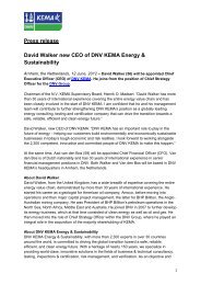
A turbo generator rotor mainly<br />
consists <strong>of</strong> the following components<br />
■■<br />
Rotor body<br />
■■<br />
Windings<br />
■■<br />
End winding retaining rings<br />
■■<br />
Rotating rectifier
10 ENERGY Non-destructive <strong>testing</strong> & plant diagnostics<br />
The poles <strong>of</strong> the stationary field assembly are excited by an<br />
auxiliary winding in the generator stator via a voltage regulator.<br />
Optionally, the supply can also be provided by a pilot exciter. The<br />
three-phase current generated in the <strong>rotating</strong> armature <strong>of</strong> the<br />
main exciter is rectified via <strong>rotating</strong> diodes <strong>and</strong> conducted to the<br />
rotor winding <strong>of</strong> the turbogenerator via copper conductors in the<br />
shaft center. Basically, the diodes convert the alternating current<br />
output <strong>of</strong> the exciter generator to direct current, which is then<br />
fed to the rotor winding <strong>of</strong> the generator.<br />
<strong>DNV</strong> KEMA performs visual inspections with regard to the<br />
functioning <strong>of</strong> these <strong>rotating</strong> diodes. With a static excitation<br />
system the rotor field current to the <strong>rotating</strong> field winding <strong>of</strong><br />
the generator is supplied via slippings.<br />
The conductor bundle consists <strong>of</strong> a number <strong>of</strong> single conductors<br />
ranging from a few numbers in very small motors to more than<br />
200 in large turbine type generators. Depending on the type<br />
<strong>of</strong> machine <strong>and</strong> rated voltage <strong>and</strong> current the conductors are<br />
connected in series or in parallel. These conductors have to be<br />
insulated due to the different voltages. This insulation is stressed,<br />
but mainly by temperature <strong>and</strong> voltage transients. A challenge<br />
on its own is the part <strong>of</strong> the winding that is outside the core: the<br />
end windings. The sole function <strong>of</strong> these windings is to guide the<br />
current from the conductors in one slot to those in another slot.<br />
Stators<br />
The stator <strong>of</strong> a 3-phase <strong>rotating</strong> <strong>electrical</strong> machine, regardless<br />
whether it is synchronous or asynchronous, is the most expensive<br />
part <strong>of</strong> the machine. Here the energy <strong>of</strong> the magnetic field is<br />
transferred in <strong>electrical</strong> energy or vice versa. Phyiscally, the largest<br />
part <strong>of</strong> the stator is the core that carries the magnetic flux <strong>and</strong><br />
also holds the windings. Within these windings the conductor<br />
bundles carry the electric current that flows due to the voltage<br />
induced by the magnetic flux. The main insulation in between<br />
the conductor bundle <strong>and</strong> the core has to deal with dielectric<br />
stress, temperatrue, different thermal expansion <strong>of</strong> the core <strong>and</strong><br />
the copper in the conductors <strong>and</strong> vibrations, <strong>and</strong> in some cases in<br />
difficult ambient conditions.
Non-destructive <strong>testing</strong> & plant diagnostics<br />
ENERGY 11<br />
Being built up entirely from copper <strong>and</strong> insulation materials,<br />
end windings are complex mechanical constructions that are<br />
especially vulnerable to transient over currents <strong>and</strong> suffer easily<br />
due to vibrations.<br />
Last, but not least, there is insulation material in the core<br />
itself which is necessary to avoid circulating currents between<br />
the core sheets. This material is also stressed, but mainly due<br />
to temperature.<br />
Important questions are the quality during start-up, the<br />
speed <strong>of</strong> aging, the condition at a given moment in time <strong>and</strong><br />
the remaining lifetime from that moment on. A number <strong>of</strong><br />
(diagnostic) tools has been developed to furnish answers to all<br />
these questions.<br />
Generator coolers<br />
The cooling medium at larger generators is hydrogen (H2). The<br />
advantage <strong>of</strong> this gas is its lack <strong>of</strong> viscosity <strong>and</strong> sufficient specific<br />
heat capacity. However, an obvious disadvantage is its inflammable<br />
character. Leaks in these coolers that are built in the generator<br />
housing lead to sudden outages <strong>and</strong> costly repairs. These coolers<br />
should be checked regularly in order to reduce chances <strong>of</strong><br />
leaking. With Eddy Current technology <strong>and</strong> combined visual<br />
inspection this can be performed quite efficiently. There is no<br />
budgetary reason not to check these during generator revisions,<br />
whereas the benefits <strong>of</strong> having early warnings can be large.
12<br />
ENERGY<br />
Non-destructive <strong>testing</strong> & plant diagnostics<br />
Mechanical <strong>testing</strong> <strong>of</strong> rotors<br />
<strong>and</strong> stators<br />
Safe operations with flaw indications<br />
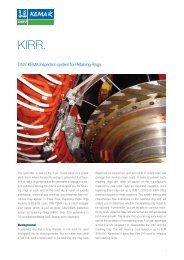
Retaining ring inspections<br />
Replacing retaining rings is quite an expensive operation, it may<br />
even cost up to EUR 1,000,000. The <strong>DNV</strong> KEMA Inspection<br />
system <strong>of</strong> Retaining Rings (KIRR) <strong>of</strong>fers a perfect solution<br />
to these problems. This system detects <strong>and</strong> characterizes flaw<br />
indications in the retaining ring <strong>and</strong> will enable you to determine<br />
whether the retaining ring needs to be replaced. Furthermore,<br />
you will be able to continue monitoring newly detected flaw<br />
indications that are still acceptable to be worked with. This<br />
means that you can regularly keep an eye on the condition <strong>of</strong> the<br />
retaining rings. Initially <strong>DNV</strong> KEMA will try to obtain as much<br />
information as possible about the ring’s geometry <strong>and</strong> the actual<br />
access to the rotor, sometimes there is hardly any information<br />
available. The ring’s geometry is then first measured using an<br />
ultrasonic C-scan mapping technique. Ultrasonic crack detection<br />
is focused on the shrunk connections <strong>and</strong> wall thickness steps.<br />
The ring’s coating is left in place. Geometry <strong>and</strong> flaw data<br />
are then fed into a computer model. The residual life span is<br />
embedded in the analysis.<br />
Bump <strong>testing</strong> <strong>of</strong> stator end windings<br />
With bump <strong>testing</strong> the natural response <strong>of</strong> an end winding is<br />
measured upon excitation with a mechanical impulse (hammer).<br />
The response is fully determined by the properties <strong>and</strong><br />
mechanical structure <strong>of</strong> the stator end winding. This principle is<br />
comparable to the excitation <strong>of</strong> piano strings by their hammers<br />
when vibrating in distinct frequencies <strong>and</strong> thus producing a tone.<br />
A relative simple method when compared with the end winding,<br />
but nevertheless the natural vibration frequencies <strong>of</strong> a complex<br />
part can be measured accurately. An acceleration transducer<br />
is mounted successively on each end winding unter test. The<br />
measured signals are fed into a data analyzer <strong>and</strong> the response<br />
frequencies <strong>and</strong> magnitudes, the so-called Power Spectrum<br />
Density (PSD), is recorded, showing the energy distribution <strong>of</strong><br />
vibrations. An extra acceleration transducer is mounted at the<br />
hammer. The most important frequency range for analysis lies<br />
between 95 <strong>and</strong> 110 Hz. Depending on temperature resonance,<br />
modes can shift slightly during operation. Electromagnetic<br />
forces at the windings have a frequency <strong>of</strong> 100 Hz. When natural<br />
vibrations lie close to 100 Hz, resonance may occur resulting in
Non-destructive <strong>testing</strong> & plant diagnostics<br />
ENERGY 13<br />
high movement <strong>of</strong> the end windings <strong>and</strong> high wear, resulting<br />
in even higher vibration magnitudes et cetera, culminating<br />
in collapse. The frequency spectrum which is measured by its<br />
acceleration transducer lies in the range <strong>of</strong> 20 to 200 Hz <strong>and</strong><br />
delivers the “base spectrum” that is induced in the object under<br />
test. Frequency Response Analysis is used with which the obtained<br />
frequency spectra from the end winding are divided with this base<br />
spectrum, yielding a “normalized” signal.<br />
Wedges<br />
In order to support windings <strong>of</strong> <strong>electrical</strong> <strong>machines</strong> in the slots<br />
<strong>of</strong> rotors or stators, various wedges are used that are capable<br />
<strong>of</strong> withst<strong>and</strong>ing the mechanical <strong>and</strong> <strong>electrical</strong> stresses acting<br />
on the windings during steady state <strong>and</strong> dynamic behavior <strong>of</strong><br />
the machine. In combination with liners, blocks <strong>and</strong> other<br />
materials, they maintain the position <strong>of</strong> slot windings <strong>and</strong> end<br />
windings, without causing heavy stray currents, short-circuit<br />
currents, <strong>and</strong> without vibration <strong>of</strong> the windings. Furthermore,<br />
all these tools are capable <strong>of</strong> withst<strong>and</strong>ing the high temperature<br />
stresses in the machine. It is <strong>of</strong> paramount importance that<br />
the wedges <strong>and</strong> other supporting materials do not loose their<br />
supporting capabilities during service, that these are not subject<br />
to degradation <strong>and</strong> that they remain fixed, without any space for<br />
vibration, noise generation, risk <strong>of</strong> getting loose <strong>and</strong> that under<br />
no circumstances any part may interfere with the rotation <strong>of</strong><br />
the machinery. Any refurbishing <strong>of</strong> the machine shall include<br />
a thorough inspection <strong>and</strong> check <strong>of</strong> all winding supporting<br />
materials.<br />
Generator bore examinations “BoreSonics”<br />
Boresonics encompasses a series <strong>of</strong> operations <strong>and</strong> examinations<br />
conducted on generator rotors with central bores through<br />
their forgings. Lessons are learned from a catastrophic event,<br />
as such is the case for the in-service practice <strong>of</strong> examining the<br />
near surface volume <strong>of</strong> material in generators with central<br />
bores. The honing process serves to remove any oxides that<br />
may have formed that would interfere with subsequent surface<br />
examinations such as visual, magnetic particle or Eddy currents.<br />
It also provides a means to remove a layer <strong>of</strong> material that may<br />
have become embrittled <strong>and</strong> subject to crack initiation. The<br />
process also produces a smooth uniform surface that resists stress<br />
concentrations.<br />
<strong>DNV</strong> KEMA has developed a field transportable horizontal honing<br />
system. This system provides surface preparation on bores from 70<br />
to 250 mm (2.75 – 10 inches) in diameter, <strong>and</strong> bore lengths <strong>of</strong> up<br />
to 13.2 meters (40 feet). The system allows you to let <strong>DNV</strong> KEMA<br />
accomplish a full range <strong>of</strong> tasks associated with the required bore<br />
inspections, like:<br />
■■<br />
Visual examination<br />
■■<br />
Magnetic particle examination<br />
■■<br />
Eddy current examination<br />
■■<br />
Ultrasonic examination<br />
■■<br />
Follow-up services
14<br />
ENERGY<br />
Non-destructive <strong>testing</strong> & plant diagnostics<br />
Electric <strong>testing</strong> <strong>of</strong> rotors<br />
DC-resistance <strong>of</strong> the rotor windings<br />
In order to detect the presence <strong>of</strong> defects in the rotor windings<br />
current path, the DC-resistance <strong>of</strong> the stator windings is determined<br />
by means <strong>of</strong> a DC-current, which is conducted through the rotor<br />
winding in series with a calibrated shunt. The test is normally<br />
performed between the slip rings. The DC-current must be large<br />
enough to enable accurate measurements, but shall not result in<br />
significant thermal effects during the measurement. The voltage<br />
across the shunt <strong>and</strong> the rotor winding is compared. During the<br />
measurements the temperature <strong>of</strong> the winding is recorded.<br />
For evaluation <strong>of</strong> the results a comparison is made with previous<br />
measuring results, such as obtained by the manufacturer in the<br />
factory.<br />
Voltage withst<strong>and</strong> tests<br />
on the rotor windings<br />
Verification <strong>of</strong> the condition <strong>of</strong> the <strong>electrical</strong> coil insulation <strong>of</strong> rotor<br />
windings may be done by Megger <strong>testing</strong> followed by application <strong>of</strong> a<br />
prescribed power frequency voltage for some time. The coil insulation<br />
to earth or to neighbouring coils is tested with short-circuited rotor<br />
windings. Generally the voltage will be less than the level <strong>of</strong> the original<br />
factory acceptance test.<br />
For this purpose the results mostly are corrected to a temperature<br />
<strong>of</strong> 75°C. If the results are deviating from the expected values<br />
the cause should be traced. Any bad connection or defect in the<br />
terminals or (partly) interruption in the windings or leads may<br />
cause large damage to the machine.<br />
Impedance <strong>of</strong> the rotor windings<br />
In order to detect presence <strong>of</strong> defects in the rotor windings<br />
current path, the 50/60 Hz power frequency impedance <strong>of</strong> the<br />
stator windings is determined by means <strong>of</strong> an AC-current, which<br />
is conducted through the rotor winding. Then voltage across the<br />
slip rings is measured. The test is normally performed between<br />
the slip rings. The AC-current must be large enough to enable<br />
accurate measurements but shall not result in significant thermal<br />
effects during the measurement. Subsequently the 50/60 Hz<br />
power frequency impedance <strong>of</strong> the rotor winding was determined.<br />
The accuracy <strong>of</strong> the measurement depends on several factors.<br />
For instance the wave shape <strong>of</strong> the harmonic current may be<br />
crucial. For evaluation <strong>of</strong> the results, a comparison is made with<br />
previous measuring results, such as obtained by the manufacturer<br />
in the factory.
Non-destructive <strong>testing</strong> & plant diagnostics<br />
ENERGY 15<br />
RSO-measurement on the rotor windings<br />
In order to test the performance <strong>of</strong> the rotor windings RSO<br />
(Recurrent Search Oscillogram) measurements are conducted.<br />
For the test a transient signal with respect to the rotor shaft is<br />
injected in each <strong>of</strong> the slip rings. A voltage impulse generator is<br />
connected between one <strong>of</strong> the slip rings in turn <strong>and</strong> the rotor<br />
shaft. The impulse voltage <strong>and</strong> the resulting current are fed into a<br />
transient recorder. The admittance as a function <strong>of</strong> the frequency<br />
will be determined as the twenty-fold logarithmic ratio <strong>of</strong> current<br />
<strong>and</strong> voltage, for each frequency component resulting from the<br />
Fourier transform <strong>and</strong> is expressed in dB. From the resulting<br />
current the admittance can be derived. The admittance <strong>of</strong> the<br />
two branches <strong>of</strong> the rotor winding relative to the rotor shaft will<br />
be measured. The admittance characteristics should show no<br />
difference.<br />
The test is performed with the rotor in st<strong>and</strong>still mode, or<br />
if possible, in running mode, at various speed adjustments.<br />
Additional information about the condition <strong>of</strong> the rotor windings<br />
can be found by comparison <strong>of</strong> the transient behavior <strong>of</strong><br />
symmetrical winding branches, each connected to a slip ring.<br />
Insulation resistance <strong>of</strong> the rotor windings <strong>and</strong><br />
determination <strong>of</strong> the polarization index<br />
To determine the polarization index <strong>and</strong> insulation resistance <strong>of</strong><br />
rotor windings a dedicated test can be performed. The insulation<br />
resistance <strong>of</strong> the rotor windings is measured by means <strong>of</strong> a digital<br />
Megger. During the measurement a DC-voltage <strong>of</strong> approximately<br />
500 V is applied. The measurements are performed as a function<br />
<strong>of</strong> the time after application <strong>of</strong> the voltage. The measurements<br />
are performed on the rotor winding with the other machine<br />
winding earthed, together with the frame <strong>of</strong> the stator.<br />
It is important to register the temperature <strong>of</strong> the winding for the<br />
evaluation <strong>of</strong> the result.<br />
The leakage current that occurs when the winding insulation is<br />
subjected to a DC-voltage is a measure for the condition <strong>of</strong> its<br />
insulation. A distinction can be made here between the timedependent<br />
effects during the charging <strong>of</strong> the winding capacitance<br />
<strong>and</strong> the non-time-dependent effects which occur as a result <strong>of</strong><br />
moisture <strong>and</strong>/or tracking inside or on the surface <strong>of</strong> the winding<br />
insulation. The leakage current is measured at a specified DCvoltage<br />
level by means <strong>of</strong> an insulation resistance meter (Megger).<br />
From the measured insulation resistance as a function <strong>of</strong> the time,<br />
the polarization index is determined. The ratio <strong>of</strong> the insulation<br />
resistance values measured 10 minutes <strong>and</strong> 1 minute after the<br />
application <strong>of</strong> the DC-voltage, is called the polarization index. The<br />
polarization index <strong>and</strong> the insulation time constant are measures<br />
for the evaluation <strong>of</strong> the insulation condition with respect to<br />
cleanliness <strong>and</strong> the presence <strong>of</strong> moisture. The temperature <strong>of</strong> the<br />
winding is <strong>of</strong> importance.<br />
The admittance is presented in curves for the circuit inner slip ring to<br />
shaft (curves inner long <strong>and</strong> inner short) <strong>and</strong> for the circuit outer slip<br />
ring to shaft (curves outer long <strong>and</strong> outer short). The expression short<br />
<strong>and</strong> long relates to the length <strong>of</strong> the applied interconnecting cable wires<br />
between pulse generator <strong>and</strong> rotor. The length <strong>of</strong> the cable wires is <strong>of</strong><br />
minor importance on the measurement. Furthermore, for frequencies up<br />
to 20 kHz, the admittance <strong>of</strong> both circuits is identical.
16<br />
ENERGY Non-destructive <strong>testing</strong> & plant diagnostics<br />
Electric <strong>testing</strong> <strong>of</strong> stators<br />
Reliable operation <strong>of</strong> a generator is highly dependent on the <strong>electrical</strong> <strong>and</strong> mechanical integrity <strong>of</strong> stator winding. Operating<br />
temperature, operating voltage stress <strong>and</strong> thermal-cycle stress cause damage to the stator insulation.<br />
Failure <strong>of</strong> a generator stator conductor due to <strong>electrical</strong> or<br />
mechanical problems will lead to long forced outage <strong>of</strong> the unit<br />
resulting into huge revenue loss. Therefore it is necessary<br />
for judgment <strong>of</strong> insulation deterioration to carry out a<br />
diagnostic test <strong>of</strong> the stator coil.<br />
To evaluate the residual life from experience <strong>and</strong> the<br />
accumulated data, <strong>DNV</strong> KEMA <strong>of</strong>fers a full set <strong>of</strong> diagnostics to<br />
assess the generator stator condition, like:<br />
■■<br />
Insulation resistance<br />
■■<br />
Polarization index<br />
■■<br />
Capacitance <strong>and</strong> dielectric losses<br />
■■<br />
Partial discharge<br />
■■<br />
Voltage tests<br />
Measurement <strong>of</strong> the DC-resistance <strong>of</strong> the<br />
stator windings<br />
In order to detect presence <strong>of</strong> defects in the stator windings<br />
current path, the DC-resistance <strong>of</strong> the rotor windings is<br />
determined by means <strong>of</strong> a DC-current, which is conducted<br />
through the stator winding in series with a calibrated shunt.<br />
The test is normally performed between the slip rings.<br />
The DC-current must be large enough to enable accurate<br />
measurements but shall not result in significant thermal effects<br />
during the measurement. The voltage across the shunt <strong>and</strong><br />
the stator winding is compared. During the measurements the<br />
temperature <strong>of</strong> the winding is recorded.<br />
For evaluation <strong>of</strong> the results a comparison is made with previous<br />
measuring results, such as obtained by the manufacturer in<br />
the factory. For this purpose the results are mostly corrected<br />
to a temperature <strong>of</strong> 75°C. If the results are deviating from the<br />
expected values the cause should be traced. Any bad connection<br />
or defect in the terminals or (partly) interruption in the<br />
windings or leads may cause large damage to the machine.<br />
Insulation resistance <strong>and</strong> polarization index <strong>of</strong><br />
stator windings<br />
To determine the polarization index <strong>and</strong> insulation resistance<br />
<strong>of</strong> stator windings a dedicated test is performed. The insulation<br />
resistance <strong>of</strong> the stator windings is measured by means <strong>of</strong> a<br />
digital Megger. During the measurement a DC-voltage is applied<br />
ranging from 500 – 5000 V. The measurements are performed<br />
as a function <strong>of</strong> the time after application <strong>of</strong> the voltage. The<br />
measurements are performed on the stator winding with the
Non-destructive <strong>testing</strong> & plant diagnostics<br />
ENERGY 17<br />
other machine winding earthed, together with the frame <strong>of</strong> the<br />
rotor. It is important to register the temperature <strong>of</strong> the winding<br />
for the evaluation <strong>of</strong> the result.<br />
A distinction can be made here between the time-dependent<br />
effects during the charging <strong>of</strong> the winding capacitance <strong>and</strong><br />
the non-time-dependent effects which occur as a result <strong>of</strong><br />
moisture <strong>and</strong>/or tracking inside or on the surface <strong>of</strong> the<br />
winding insulation. From the measured insulation resistance as a<br />
function <strong>of</strong> the time, the polarization index is determined. The<br />
ratio <strong>of</strong> the insulation resistance values measured 10 minutes<br />
<strong>and</strong> 1 minute after the application <strong>of</strong> the DC-voltage, is called<br />
the polarization index. The polarization index <strong>and</strong> the<br />
insulation time constant are measures for the evaluation <strong>of</strong> the<br />
insulation condition with respect to cleanliness <strong>and</strong> the presence<br />
<strong>of</strong> moisture. The temperature <strong>of</strong> the winding is <strong>of</strong> importance.<br />
For modern epoxy-resin insulated windings the insulation<br />
resistance should be more than 1000 MΩ at 20˚C <strong>and</strong> the<br />
polarization index PI should be in accordance with the IEEE 43<br />
st<strong>and</strong>ard.<br />
Capacitance <strong>and</strong> dielectric losses (Tan-δ)<br />
Dielectric losses <strong>and</strong> capacitance <strong>of</strong> the winding will increase<br />
with the voltage because voids (gaps) inside the insulation will<br />
be short-circuited as a result <strong>of</strong> occurring partial discharges.<br />
The dielectric losses <strong>of</strong> the insulation represent the relation <strong>of</strong><br />
the resistance to the capacitive impedance. The dielectric losses<br />
depend on temperature <strong>and</strong> frequency. The capacitance <strong>of</strong> the<br />
winding at 0.2U n is <strong>of</strong> vital importance to find out whether major<br />
changes have occurred in the insulation. The capacitance <strong>of</strong><br />
the windings depends on the relative dielectric constant <strong>of</strong> the<br />
insulation. The capacitance is subject <strong>of</strong> voids <strong>and</strong> gaps in the<br />
insulation.<br />
For the purpose <strong>of</strong> these measurements a Schering bridge is<br />
used with a loss-free st<strong>and</strong>ard capacitor. The measurements are<br />
performed as a function <strong>of</strong> the voltage between for example 0.2<br />
<strong>and</strong> 1.0U n in steps <strong>of</strong> 0.1U n.<br />
The measurements can be performed part-wise, mostly per<br />
phase, on the individual parts <strong>of</strong> winding with the other parts<br />
connected to earth <strong>and</strong> to the stator frame. The dielectric<br />
loss angle <strong>of</strong> the insulation <strong>and</strong> the capacitance <strong>of</strong> the stator<br />
windings are determined. The measurement can be done very<br />
accurately <strong>and</strong> reliable.<br />
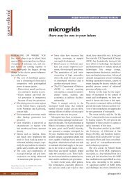
In order to assess the condition <strong>of</strong><br />
the generator stator, <strong>DNV</strong> KEMA <strong>of</strong>fers<br />
a full set <strong>of</strong> diagnostics such as<br />
■■<br />
Insulation resistance<br />
■■<br />
Polarization index<br />
■■<br />
Capacitance <strong>and</strong> dielectric losses<br />
■■<br />
Partial discharge<br />
■■<br />
Voltage tests
18<br />
ENERGY<br />
Non-destructive <strong>testing</strong> & plant diagnostics<br />
From the average value <strong>of</strong> the maximum rise <strong>of</strong> Tan-δ with<br />
voltage, compared with the values obtained during previous<br />
measurements, it can be determined whether the volume <strong>of</strong><br />
air inside the insulation has changed. The relative capacitance<br />
change is a measure for the total air volume which is shortcircuited<br />
by internal partial discharges.<br />
Partial discharges<br />
Partial discharges may occur due to discontinuities in the<br />
insulation. Partial discharges give an indication <strong>of</strong> abnormalities.<br />
It is important to know how the test is performed. The partial<br />
discharge measurements are performed with a multi-channel,<br />
phase-related partial discharge detector. Prior to each test, a<br />
calibration is performed on each side <strong>of</strong> the generator winding<br />
by means <strong>of</strong> an impulse-generator giving a repeating pulse with<br />
known partial discharge intensity. During the partial discharge<br />
measurements the entire winding - from phase connection to<br />
star point - is energized at a certain voltage level with respect to<br />
earth. In practice, when the machine is under normal service<br />
conditions, the voltage is distributed equally along the winding<br />
from the star point <strong>of</strong> the machine to the phase connection.<br />
Different partial discharges:<br />
■■<br />
Slot discharges occur in a slot in the stator between the bar<br />
including its insulation <strong>and</strong> the stator. This can be the result<br />
<strong>of</strong> degradation or damage to the semi-conducting layer on the<br />
surface <strong>of</strong> the bar insulation.<br />
The partial discharges are recorded during a period <strong>of</strong> approximately one<br />
minute at voltage levels <strong>of</strong> 0.6U n <strong>and</strong> 1.0U n at a frequency <strong>of</strong> 50 Hz. Based<br />
on these measurements, graphs can be plotted in which the intensity <strong>of</strong><br />
the partial discharge level is presented as a function <strong>of</strong> the phase angle at<br />
which the discharge occurred. Within these graphs, different intensities are<br />
presented in different colors. The graphs can contribute to the interpretation<br />
<strong>of</strong> the test result, since the shape <strong>of</strong> a partial discharge pattern depends<br />
on the location where the discharges occur. Some <strong>of</strong> the recorded patterns<br />
show an asymmetry between the discharges in the positive <strong>and</strong> negative<br />
half-cycle <strong>of</strong> the voltage sine wave. This is typical for discharges other than<br />
internal discharges, which show a more symmetrical pattern.
Non-destructive <strong>testing</strong> & plant diagnostics ENERGY 19<br />
■■<br />
End winding discharges can occur at the location where the bar<br />
extends out <strong>of</strong> the slot. To prevent partial discharges a corona<br />
protection layer is applied at this location. When this layer is<br />
damaged, partial discharges can occur here.<br />
■■<br />
Internal discharges occur in the insulation around the<br />
conductors, mostly caused by detachment <strong>of</strong> the different<br />
layers in the insulation (delamination). Gaps/voids, originated<br />
during the manufacturing process, can also be the cause for<br />
this type <strong>of</strong> partial discharges.<br />
■■<br />
Bar-to-bar discharges can occur at the end winding between<br />
two bars <strong>of</strong> different phases or between a bar at high-voltage<br />
<strong>and</strong> a neutral bar. In general, this type <strong>of</strong> discharge can occur<br />
between two separate bars next to each other when a too high<br />
voltage difference exists between them resulting in a too high<br />
<strong>electrical</strong> field.<br />
Voltage withst<strong>and</strong> tests on the stator windings<br />
As a further check on the insulation <strong>of</strong> the stator windings, <strong>and</strong><br />
depending partly on the size <strong>of</strong> the generator (or motor), it<br />
may be desirable to perform a voltage test, as well as measuring<br />
the capacity, loss angle <strong>and</strong> partial discharges. The test method,<br />
appropriate voltage strength <strong>and</strong> test duration are preferably<br />
decided on the basis <strong>of</strong> consultation with the user <strong>and</strong><br />
manufacturer.<br />
ElCID test<br />
Defects in inter-laminar insulations <strong>of</strong> stator cores in <strong>rotating</strong><br />
<strong>electrical</strong> <strong>machines</strong> such as generators <strong>and</strong> electro motors cause<br />
fault currents to flow locally in the core, which may result in<br />
local overheating or hot spots in damaged areas. These hot<br />
spots should be detected <strong>and</strong> repaired during routine machine<br />
overhauls. The conventional <strong>testing</strong> method for measuring these<br />
core faults is known as the full ring flux <strong>testing</strong> method. This<br />
methodology requires the core to be excited to near its normal<br />
working flux level for a period <strong>of</strong> time.<br />
An alternative method to detect faults in core inter-lamination<br />
insulation by electromagnetic means was developed in 1978.<br />
Instead <strong>of</strong> the full flux working level, this newer method uses<br />
only a small fraction <strong>of</strong> excitation to generate fault currents<br />
within the core body which are sensed by a pick-up coil. This<br />
provides an accurate indication <strong>of</strong> damaged parts, including<br />
tooth tips <strong>and</strong> slot walls, <strong>and</strong> possible surface damage, without<br />
the normal problems when <strong>testing</strong> with high excitation. This<br />
methodology is called the ELectromagnetic Core Imperfection<br />
Detector (ELCID) <strong>and</strong> is accepted worldwide for reliable <strong>and</strong><br />
safe detection <strong>of</strong> stator core inter-laminar faults.<br />
ELCID operates at only 4% <strong>of</strong> the normal operating flux. This<br />
low flux is generated by a portable, quickly installed excitation<br />
kit. Any imperfection in the core inter-laminar insulation<br />
produces fault currents, which are detected by a Chattock<br />
coil <strong>and</strong> analyzed by the ELCID signal-processing unit. These<br />
Chattock coils are mounted on a Generator Inspection Vehicle<br />
(GIV), which is developed by <strong>DNV</strong> KEMA, in order to perform<br />
the ELCID test without necessity <strong>of</strong> removing the rotor.<br />
Measurement results are digitally stored for analysis <strong>and</strong> report<br />
generation to precisely locate the faults in the stator core.<br />
Future results can be compared to past results for trend analysis.<br />
This GIV is also used when <strong>testing</strong> stator wedges on integrity <strong>and</strong><br />
eventual detachment (tap <strong>testing</strong>). The vehicle is then provided<br />
with equipment for mechanical excitation <strong>of</strong> the wedges <strong>and</strong><br />
detection <strong>of</strong> the impulse response (WTA: Wedge Tightness<br />
Assessment). Cameras are mounted on the GIV in order to<br />
perform various visual inspections.<br />
Key benefits <strong>of</strong> the ELCID test<br />
■■<br />
Tests are repeatable<br />
■■<br />
Immediate test results available for local analysis<br />
■■<br />
Determination <strong>of</strong> exact location <strong>of</strong> defects: on the (sub)surface<br />
or under conductors<br />
■■<br />
Tests with or without windings in place<br />
■■<br />
Allows partial retests <strong>of</strong> a core, results can be merged to obtain<br />
a complete view <strong>of</strong> the core condition<br />
■■<br />
Tests can be performed with the rotor in-situ
N.V. KEMA<br />
Utrechtseweg 310, 6812 AR Arnhem, The Netherl<strong>and</strong>s I Tel: +31 26 356 9111 I Fax: +31 26 443 4025<br />
emea@dnvkema.com I www.dnvkema.com<br />
About <strong>DNV</strong> KEMA Energy & Sustainability<br />
<strong>DNV</strong> KEMA Energy & Sustainability, with more than 2,300 experts in over 30 countries around the world,<br />
is committed to driving the global transition toward a safe, reliable, efficient, <strong>and</strong> clean energy future.<br />
With a heritage <strong>of</strong> nearly 150 years, we specialize in providing world-class, innovative solutions in the fields<br />
<strong>of</strong> business & technical consultancy, <strong>testing</strong>, inspections & certification, risk management, <strong>and</strong> verification.<br />
As an objective <strong>and</strong> impartial knowledge-based company, we advise <strong>and</strong> support organizations along the<br />
energy value chain: producers, suppliers & end-users <strong>of</strong> energy, equipment manufacturers, as well as<br />
government bodies, corporations <strong>and</strong> non-governmental organizations. <strong>DNV</strong> KEMA Energy & Sustainability<br />
is part <strong>of</strong> <strong>DNV</strong>, a global provider <strong>of</strong> services for managing risk with more than 10,000 employees in over<br />
100 countries.<br />
Present around the globe<br />
■■<br />
Management & Operations Consulting<br />
■■<br />
Cleaner Energy Services<br />
■■<br />
Electricity Transmission & Distribution<br />
■■<br />
Sustainable Use Services<br />
■■<br />
Transportation Systems<br />
■■<br />
Gas Consulting & Services<br />
■■<br />
Testing, Inspections & Certification<br />
■■<br />
Accredited Climate Change Services<br />
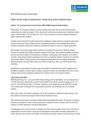
Office locations<br />
■■<br />
Office locations<br />
Agents / Business partners<br />
Agents / Business partners<br />
ETD.12012.E&O.05