column phase selection guide troubleshooting tools ... - Phenomenex
column phase selection guide troubleshooting tools ... - Phenomenex
column phase selection guide troubleshooting tools ... - Phenomenex

Create successful ePaper yourself
Turn your PDF publications into a flip-book with our unique Google optimized e-Paper software.
Polar<br />
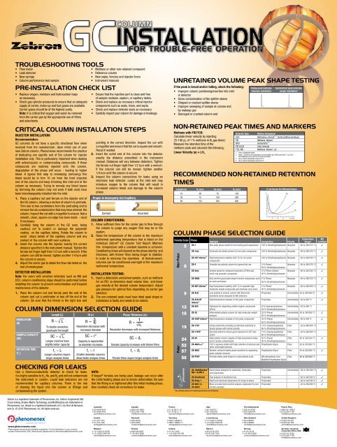
TROUBLESHOOTING TOOLS<br />
• Flow meter<br />
• Leak detector<br />
• New syringe<br />
• Column performance test sample<br />
PRE-INSTALLATION CHECK LIST<br />
• Replace oxygen, moisture and hydrocarbon traps<br />
as necessary.<br />
• Check gas cylinder pressures to ensure that an adequate<br />
supply of carrier, make-up and fuel gases are available.<br />
Carrier gases should be of the highest purity.<br />
Note: It is critical that oxygen and water be removed<br />
from the carrier gas by the appropriate use of filters<br />
and adsorbents.<br />
CRITICAL COLUMN INSTALLATION STEPS<br />
INJECTOR INSTALLATION:<br />
Recommendation:<br />
GC <strong>column</strong>s do not have a specific directional flow when<br />
received from the manufacturer. Upon initial use of your<br />
new Zebron <strong>column</strong>, <strong>Phenomenex</strong> recommends the practice<br />
of dedicating one specific end of the <strong>column</strong> for injector<br />
installation only. This is particularly important when dealing<br />
with active/caustic or contaminating compounds. If these<br />
compounds are routinely injected onto the <strong>column</strong>,<br />
degradation of the <strong>phase</strong> will occur - leading to higher<br />
bleed. A typical first step to remedying (removing) this<br />
bleed would be to trim 10 cm from the front (injector)<br />
end of the <strong>column</strong> and keep trimming this inlet end of the<br />
<strong>column</strong> as necessary. Trying to remedy any bleed issues<br />
by trimming the <strong>column</strong> may not work if both ends have<br />
been interchangeably installed into the inlet.<br />
1. Place a capillary nut and ferrule on the injector end of<br />
the GC <strong>column</strong>, allowing a section of <strong>column</strong> to protrude.<br />
Trim one to two centimeters from the protruding end to<br />
remove ferrule contamination that may have entered the<br />
<strong>column</strong>. Inspect the cut with a magnifier to ensure that a<br />
smooth, clean, square-cut edge has been made - recut<br />
if necessary.<br />
2. Carefully hang the <strong>column</strong> in the GC oven, being<br />
cautious not to scratch or damage the polyimide<br />
coating on the capillary tubing. Rotate the <strong>column</strong> to<br />
avoid sharp bends of the capillary <strong>column</strong> and any<br />
contact of the <strong>column</strong> with oven surfaces.<br />
3. Insert the <strong>column</strong> into the injector exactly the correct<br />
distance specified in the instrument manual. Tighten the<br />
ferrule nut finger-tight then 1/2 turn with a wrench. If the<br />
<strong>column</strong> can still be moved, tighten another 1/4 turn until<br />
the <strong>column</strong> is secure.<br />
4. Adjust the carrier gas to obtain the flow rate listed on the<br />
test chromatogram.<br />
DETECTOR INSTALLATION:<br />
Note: For users with sensitive detectors such as MS and<br />
ECD, <strong>column</strong> conditioning steps should be performed before<br />
installing the <strong>column</strong> to prevent contamination and frequent<br />
maintenance of the detector.<br />
1. Place the <strong>column</strong> nut and ferrule past the end of the<br />
<strong>column</strong> and cut a centimeter or two off the end of the<br />
<strong>column</strong>. Be sure that the ferrule is the right size and<br />
• Methane or other non-retained compound<br />
• Reference <strong>column</strong><br />
• New septa, ferrules and injector liners<br />
• Instrument manuals<br />
• Ensure that the injection port is clean and free<br />
of sample residues, septum, or capillary debris.<br />
• Check and replace as necessary critical injector<br />
components such as seals, liners, and septa.<br />
• Check and replace detector seals as necessary.<br />
• Carefully inspect your <strong>column</strong> for damage or breakage.<br />
pointing in the correct direction. Inspect the cut with<br />
a magnifier and ensure that the cut is square and smooth.<br />
Recut if needed.<br />
2. Insert the outlet end of the <strong>column</strong> into the detector<br />
exactly the distance prescribed in the instrument<br />
manual. Distances will vary between detectors. Tighten<br />
the ferrule nut finger-tight then 1/2 turn with a wrench.<br />
If the <strong>column</strong> can still be moved, tighten another<br />
1/4 turn until the <strong>column</strong> is secure.<br />
3. Inspect the <strong>column</strong> connections for leaks using an<br />
electronic leak detector. Leaks at the inlet end may<br />
introduce oxygen to the <strong>column</strong> that will result in<br />
increased <strong>column</strong> bleed and damage to the <strong>column</strong><br />
<strong>phase</strong>.<br />
Proper & Improperly Cut Capillary<br />
Correct<br />
COLUMN CONDITIONING:<br />
1. Allow sufficient time for the carrier gas to flow through<br />
the <strong>column</strong> to purge any oxygen that may be in the<br />
system.<br />
2. Raise the temperature of the <strong>column</strong> to the maximum<br />
isothermal operating temperature that is listed on the<br />
individual Zebron ® GC Column Test Report. Maintain<br />
this temperature until a constant baseline is achieved.<br />
Conditioning times will depend on the <strong>phase</strong> identity and<br />
thickness, with thicker films taking longer to stabilize.<br />
In order to minimize the downtime of theinstrument,<br />
<strong>column</strong>s can be conditioned overnight at the maximum<br />
isothermal temperature.<br />
INSTALLATION TESTING:<br />
1. Inject a detectable unretained sample, such as methane<br />
for an FID, to determine dead volume time and linear<br />
gas velocity at the desired <strong>column</strong> temperature. Adjust<br />
gas pressure for optimal flow depending on carrier gas<br />
<strong>selection</strong>.<br />
2. The non-retained peak must have ideal peak shape or<br />
installation is faulty and needs to be redone.<br />
COLUMN DIMENSION SELECTION GUIDE<br />
RESOLUTION<br />
(R)<br />
SAMPLE CAPACITY<br />
(SC)<br />
RETENTION TIME<br />
(t r<br />
)<br />
Incorrect<br />
Length (L) ID (r) Phase Thickness (d f )<br />
R ~ √ — L<br />
To double resolution,<br />
quadruple the length<br />
SC ~ √ — L<br />
Longer <strong>column</strong>s have<br />
slightly better capacity<br />
t r ~ L<br />
Longer <strong>column</strong>s require<br />
longer analysis times<br />
CHECKING FOR LEAKS<br />
Use a thermoconductivity detector to check for leaks.<br />
It is highly sensitive to H 2<br />
, He, and N 2<br />
and will not contaminate<br />
the instrument or <strong>column</strong>. Liquid leak indicators are not<br />
recommended for capillary <strong>column</strong>s. There is the risk<br />
of drawing the liquid into the <strong>column</strong> or fittings and<br />
contaminating the system.<br />
R ~ r<br />
Resolution decreases with<br />
increased diameter<br />
SC ~ r 2<br />
Capacity is exponential<br />
as diameter increases<br />
t r ~ r<br />
Smaller diameter <strong>column</strong>s<br />
allow faster analysis times<br />
R ~ 1<br />
√ — d f<br />
Resolution decreases with increased thickness<br />
SC ~ d f<br />
Sample capacity increases with thicker films<br />
t r ~ d f<br />
Thicker films require longer analysis times<br />
NOTE:<br />
If Vespel ® ferrules are being used, leakage can occur after<br />
the initial heating <strong>phase</strong> due to ferrule deformation. Be sure<br />
that the fitting is re-tightened after this initial heating <strong>phase</strong>,<br />
then carefully check all corrections for leaks.<br />
UNRETAINED VOLUME PEAK SHAPE TESTING<br />
If the peak is broad and/or tailing, check the following:<br />
• Improper <strong>column</strong> positioning/insertion into inlet<br />
or detector<br />
• Gross contamination of the splitter sleeve<br />
• Chipped or cracked splitter sleeve<br />
• Improper sweeping of sample at <strong>column</strong> end<br />
by makeup gas<br />
• Damaged or crushed <strong>column</strong> end<br />
NON-RETAINED PEAK TIMES AND MARKERS<br />
Type Marker Compound<br />
Methane with FID/TCD:<br />
Detector<br />
Calculate linear velocity by injecting<br />
ECD<br />
Linear Velocity (u) = L/t o<br />
25-100 μL of 1 % methane in N 2 gas blend.<br />
Measure the retention time of the<br />
FID<br />
NPD<br />
Methane, Butane 1<br />
Acetonitrile 2, 4<br />
PID ELCD<br />
Vinyl chloride<br />
methane peak and calculate the following:<br />
TCD, MS<br />
COLUMN PHASE SELECTION GUIDE<br />
Polarity Scale<br />
5<br />
8<br />
9<br />
13<br />
18<br />
19<br />
24<br />
52<br />
57<br />
58<br />
Temperature MS<br />
Phase<br />
Highlight Composition Polarity Range* Certiftied<br />
ZB-1 Non-polar <strong>phase</strong> suited for true boiling point separations 100 % Dimethylpolysiloxane Nonpolar -60 to 360/370 °C 3<br />
ZB-1ms Extremely low bleed <strong>column</strong> for non-polar compounds 100 % Dimethylpolysiloxane Nonpolar -60 to 360/370 °C 3<br />
ZB-1HT Inferno High temperature stability (430 °C) for non-polar 100 % Dimethylpolysiloxane Nonpolar -60 to 400/430 °C 3<br />
compounds<br />
ZB-5 Versatile low polarity <strong>column</strong> for general lab use 5 %-Phenyl<br />
95 %-Dimethylpolysiloxane<br />
Nonpolar -60 to 360/370 °C 3<br />
ZB-5ms<br />
ZB-5MSi<br />
ZB-5HT Inferno <br />
ZB-XLB<br />
Arylene <strong>phase</strong> for enhanced resolution of PAHs and<br />
multi-ring aromatic compounds<br />
Very inert for good peak shape of active compounds, such<br />
as acids and bases<br />
High temperature stability (430 °C) to separate high<br />
molecular weight compounds and eliminate carry overs<br />
Low polarity si-arylene <strong>column</strong> with bleed and<br />
sensitivity levels designed for MS detectors<br />
5 %-Phenyl Arylene<br />
95 %-Dimethylpolysiloxane<br />
5 %-Phenyl<br />
95 %-Dimethylpolysiloxane<br />
Nonpolar -60 to 325/350 °C 3<br />
Nonpolar -60 to 360/370 °C 3<br />
5 %-Phenyl<br />
95 %-Dimethylpolysiloxane<br />
Nonpolar -60 to 400/430 °C 3<br />
Proprietary Intermediate 30 to 340/360 ºC 3<br />
ZB-XLB-HT High temperature anlaysis of mid-polar compounds Proprietary Intermediate -60 to 400 ºC 3<br />
Inferno <br />
ZB-624<br />
ZB-35<br />
Optimized for separating volatile organic compounds<br />
(VOCs)<br />
Intermediate polarity <strong>column</strong> for high molecular weight<br />
analysis<br />
6 %-Cyanopropylphenyl<br />
94 %-Dimethylpolysiloxane<br />
35 %-Phenyl<br />
65 %-Dimethylpolysiloxane<br />
ZB-35HT Inferno High temperature analysis of mid-polar compounds 35 %-Phenyl<br />
65 %-Dimethylpolysiloxane<br />
ZB-1701<br />
ZB-1701P<br />
ZB-50<br />
ZB-WAXPLUS <br />
ZB-WAX<br />
Unique selectivity providing an alternate selectivity to<br />
phenyl <strong>phase</strong>s with similar polarity<br />
Specially tested to ensure good response for DDT and<br />
endrin<br />
High polarity <strong>column</strong> capable of high-temperature bakeout<br />
to remove contaminants<br />
100 % aqueous stable with high retention of alcohols and<br />
other chlorinated solvents<br />
Bonded, solvent rinsable <strong>phase</strong> excellent for separating<br />
polar complex mixtures<br />
ZB-FFAP Provides better peak shape for underivatized acids Nitroterephthalic Acid<br />
Modified Polyethylene Glycol<br />
ZB- MultiResidue <br />
MR-1 & MR-2<br />
Novel <strong>phase</strong> designed for pesticides, herbicides,<br />
and insecticides<br />
Intermediate -20 to 260 °C<br />
Intermediate 50 to 340/360 °C 3<br />
Intermediate -60 to 400 ºC 3<br />
14 %-Cyanopropylphenyl<br />
86 %-Dimethylpolysiloxane<br />
Polar -20 to 280/300 °C<br />
14 %-Cyanopropylphenyl Polar -20 to 280/300 °C<br />
86 %-Dimethylpolysiloxane<br />
50 %-Phenyl<br />
Polar 40 to 320/340 °C 3<br />
50 %-Dimethylpolysiloxane<br />
Polyethylene Glycol Polar 20 to 250/260 °C<br />
Polyethylene Glycol Polar 40 to 250/260 °C 3<br />
Polar 40 to 250/260 °C<br />
Proprietary Intermediate -60 to 320/340 °C 3<br />
ZB-Bioethanol Fast analysis of bioethanol fuel Proprietary -60 to 340/360 ºC 3<br />
ZB-Drug-1 Rapid and improved separations for drugs of abuse Proprietary -60 to 320/340 ºC 3<br />
ZB-BAC1 &<br />
ZB-BAC2<br />
More accurate blood alcohol analysis, especially for post<br />
mortem samples<br />
Proprietary -20 to 260/280 ºC 3<br />
* See individual <strong>phase</strong>s for detailed specifications and limitations.<br />
Methylene chloride 2, 3 , Dichlorodifluoromethane<br />
Methane, Butane 1 , air<br />
1. From a disposable lighter<br />
2. Place 1-2 drops in an autosampler vial and tightly cap. Shake and inject 1-2 μL from<br />
the headspace of the vial. Do not inject any liquid.<br />
3. Use a <strong>column</strong> temperature above 55 ºC.<br />
4. Use a <strong>column</strong> temperature above 95 ºC.<br />
RECOMMENDED NON-RETAINED RETENTION<br />
TIMES<br />
Length (m) H 2 (sec) He (sec) N 2 (sec)<br />
Non-Polar<br />
15 38 75 150<br />
30 75 150 300<br />
60 150 300 600<br />
Tailing peak indicates<br />
improper installation<br />
Symmetrical peak indicates<br />
proper installation<br />
h (u) Curves for Different Gases<br />
Zebron is a registered trademark of <strong>Phenomenex</strong>, Inc. Inferno, Engineered Self<br />
Cross-linking, Arylene Matrix Technology, and MultiResidue are trademarks of<br />
<strong>Phenomenex</strong>, Inc. Vespel is a registered trademark of E.I. du Pont de Nemours<br />
and Co. © 2010 <strong>Phenomenex</strong>, Inc. All rights reserved.<br />
Australia<br />
t: 02-9428-6444<br />
f: 02-9428-6445<br />
auinfo@phenomenex.com<br />
Canada<br />
t: (800) 543-3681<br />
f: (310) 328-7768<br />
info@phenomenex.com<br />
France<br />
t: 01 30 09 21 10<br />
f: 01 30 09 21 11<br />
franceinfo@phenomenex.com<br />
Italy<br />
t: 051 6327511<br />
f: 051 6327555<br />
italiainfo@phenomenex.com<br />
The Netherlands<br />
t: 030-2418700<br />
f: 030-2383749<br />
nlinfo@phenomenex.com<br />
Puerto Rico<br />
t: (800) 541-HPLC<br />
f: (310) 328-7768<br />
info@phenomenex.com<br />
www.phenomenex.com<br />
<strong>Phenomenex</strong> products are available worldwide. For the distributor in your country,<br />
contact <strong>Phenomenex</strong> USA, International Department at international@phenomenex.com<br />
Austria<br />
t: 01-319-1301<br />
f: 01-319-1300<br />
anfrage@phenomenex.com<br />
Belgium<br />
t: +31 (0)30-2418700<br />
f: +31 (0)30-2383749<br />
beinfo@phenomenex.com<br />
Denmark<br />
t: 4824 8048<br />
f: 4810 6265<br />
nordicinfo@phenomenex.com<br />
Finland<br />
t: (09)4789 0063<br />
f: +45 4810 6265<br />
nordicinfo@phenomenex.com<br />
Germany<br />
t: 06021-58830-0<br />
f: 06021-58830-11<br />
anfrage@phenomenex.com<br />
Ireland<br />
t: 01 247 5405<br />
f: +44 1625-501796<br />
eireinfo@phenomenex.com<br />
Luxembourg<br />
t: +31 (0)30-2418700<br />
f: +31 (0)30-2383749<br />
nlinfo@phenomenex.com<br />
Mexico<br />
t: (55) 5018 3791<br />
f: (310) 328-7768<br />
tecnicomx@phenomenex.com<br />
New Zealand<br />
t: 09-4780951<br />
f: 09-4780952<br />
nzinfo@phenomenex.com<br />
Norway<br />
t: 81 00 20 05<br />
f: +45 4810 6265<br />
nordicinfo@phenomenex.com<br />
United Kingdom<br />
t: 01625-501367<br />
f: 01625-501796<br />
ukinfo@phenomenex.com<br />
All other countries:<br />
Corporate Office USA<br />
t: (310) 212-0555<br />
f: (310) 328-7768<br />
info@phenomenex.com
PEAKS<br />
NO PEAKS<br />
GHOST PEAKS<br />
TAILING PEAKS<br />
BROAD SOLVENT FRONTS<br />
Possible Cause:<br />
System<br />
• Clogged syringe ............................................................<br />
• Leaks ............................................................................<br />
• No carrier gas ...............................................................<br />
• Detector OFF or not lit ...................................................<br />
• Wrong injection port ......................................................<br />
• Clogged inlet sleeve ......................................................<br />
Column<br />
• Broken <strong>column</strong> ..............................................................<br />
• Plugged <strong>column</strong> ............................................................<br />
Possible Cause:<br />
System<br />
• Septum bleed ................................................................<br />
• Carry over .....................................................................<br />
• Dirty inlet ......................................................................<br />
• Contaminated gas .........................................................<br />
• Outgassing from traps ..................................................<br />
• Contaminated gas lines .................................................<br />
Column<br />
• Sample contaminated ...................................................<br />
Sample<br />
• Contaminated sample ...................................................<br />
• Contaminated flush solvent ...........................................<br />
• Possible sample degradation .........................................<br />
Possible Cause:<br />
• Contaminated or active injector liner or <strong>column</strong> ............<br />
• Dead volume due to poorly installed liner or <strong>column</strong> .....<br />
• Ragged <strong>column</strong> end ......................................................<br />
• A bad match between the polarities of stationary .........<br />
<strong>phase</strong> and the solvent<br />
• A cold region in the sample flow path ...........................<br />
• Debris in the liner or <strong>column</strong> .........................................<br />
• Injection takes too long .................................................<br />
• Split ratio is too low .......................................................<br />
• Overloading the inlet ....................................................<br />
• Some types of compounds such as alcoholic ...............<br />
amines and carboxylic acids tend to tail<br />
Possible Cause:<br />
• Bad <strong>column</strong> installation .................................................<br />
• Injector leak ..................................................................<br />
• Injection volume too large .............................................<br />
• Injection temperature too low ........................................<br />
• Split ratio is too low ......................................................<br />
• Column temperature too low .........................................<br />
• Initial <strong>column</strong> temperature too high ................................<br />
for splitless injection<br />
• Purge time too long (splitless injection) .........................<br />
Suggested Remedy:<br />
Clean or replace syringe.<br />
Check injector for leaks. Make sure <strong>column</strong> is properly installed in detector.<br />
Turn on carrier gas.<br />
Ignite or turn on detector. Reduce sample size or gas flows if solvent blew out detector.<br />
Verify correct injection port.<br />
Replace inlet liner.<br />
Inspect <strong>column</strong> and verify flow at <strong>column</strong> outlet.<br />
Cut off 5-10 cm of <strong>column</strong> ends and reinstall <strong>column</strong>. Verify flow at <strong>column</strong> outlet.<br />
Suggested Remedy:<br />
Replace septum with high-temperature, low-bleed septum.<br />
Increase final temperature and hold. Rinse syringe better.<br />
Replace inlet liner.<br />
Replace filters, scrubbers, or service purifiers. Use higher purity gasses.<br />
Replace traps.<br />
Replace or clean gas lines.<br />
Cut 50-100 cm from injector side of <strong>column</strong>. Perform an extended conditioning step. Solvent<br />
rinse <strong>column</strong>. Use glass wool in liner or decrease injection temperature, or replace <strong>column</strong>.<br />
Remake sample with higher purity/fresh solvents and clean glassware.<br />
Replace syringe flush solvent with fresh/pure solvent.<br />
Make new sample. Store samples using proper procedures. Reduce introduction of catalysts<br />
or reactive analytes in sample. Store samples in opaque or dark containers.<br />
Suggested Remedy:<br />
Clean or replace injector liner. Don’t use glass wool in the liner. Solvent rinse or replace<br />
the <strong>column</strong>.<br />
Confirm by injecting inert peak (methane). If it tails, <strong>column</strong> is not properly installed.<br />
Reinstall liner and <strong>column</strong> as necessary.<br />
Score the tubing lightly with a sapphire scribe or a ceramic scoring wafer before breaking it.<br />
Examine the end. If the break is not clean and the end square, cut the <strong>column</strong> again. Point<br />
the end down while breaking it, and reinstall the <strong>column</strong> while installing a nut and ferrule.<br />
This will prevent fragments from entering the <strong>column</strong>.<br />
Change the stationary <strong>phase</strong>. Usually polar analytes tail on non-polar <strong>column</strong>s,<br />
or dirty <strong>column</strong>s.<br />
Remove any cold zones in the flow path.<br />
Clean or replace the liner. Cut 10 cm off the end of the <strong>column</strong> and reinstall it.<br />
Improve injection technique.<br />
Increase split ratio to at least 20:1.<br />
Decrease the sample volume or dilute sample.<br />
Try a more polar <strong>column</strong>. Make a derivative of the sample.<br />
Suggested Remedy:<br />
Reinstall <strong>column</strong>.<br />
Find and fix leak.<br />
Decrease sample size or dilute 1:10.<br />
Increase injection temperature so the entire sample is vaporized “instantly.” An injection<br />
temperature higher than the temperature limit of the <strong>column</strong> will not damage the <strong>column</strong>.<br />
Increase split ratio.<br />
Increase <strong>column</strong> temperature. Use a lower boiling point solvent.<br />
Decrease the initial <strong>column</strong> temperature. Use a less volatile solvent so the initial <strong>column</strong> temperature<br />
is at least 10 °C below the boiling point of the solvent. Use a shorter purge activation time.<br />
Use a shorter purge activation time.<br />
BASELINE<br />
POSSIBLE CAUSES<br />
FOR BASELINE INSTABILITY<br />
SYSTEM<br />
• Leaks, O 2 influx<br />
• Column bleed<br />
• Septum bleed<br />
• Contaminated gases<br />
• Unequilibrated<br />
• Dirty detector<br />
• Dirty inlet<br />
• Improper flow rates<br />
• Pneumatic temperature change<br />
REFERENCE<br />
PARAMETERS UNIT SYMBOLS<br />
Retention Time of<br />
an Unretained Solute<br />
Retention Time,<br />
Measured from the Start<br />
s t o<br />
Adjusted Retention Time s t ’ R = t R - t o<br />
Peak Width<br />
(Base)<br />
Peak Width<br />
(Half Height)<br />
s<br />
s<br />
s<br />
t R<br />
W<br />
W1/2<br />
t o<br />
COLUMN<br />
• Bleed contamination<br />
• Liquid leak detector<br />
contamination<br />
Capacity Factor<br />
–<br />
(Retention Factor)<br />
k = t ’ R<br />
t o<br />
k<br />
Selectivity Factor – 2 t ’<br />
a = =<br />
R2<br />
k 1 t’ R1<br />
t’<br />
Resolution – R2<br />
-<br />
R s = 2<br />
t, R1<br />
( W 1 + W 2<br />
)<br />
Number of Theoretical Plates – N = 5.54<br />
t R t<br />
(W1/2) 2 R<br />
= 16( W ) 2<br />
t’<br />
Number of Effective Plates – R t’<br />
N eff = 5.54 (W1/2) 2 R<br />
= 16 ( W) 2<br />
Column Length cm L<br />
Height Equivalent of a<br />
Theoretical Plate (Plate Height)<br />
cm H =<br />
Effective Plate Height cm H eff =<br />
Linear Velocity of the<br />
Mobile Phase<br />
Pressure Conversions<br />
cm s -1 U =<br />
L<br />
N<br />
L<br />
N eff<br />
L<br />
t o<br />
1 bar = 100 kPa<br />
1 atm = 101.3 kPa<br />
1 psi = 6.9 kPa<br />
SAMPLE<br />
• Carry over<br />
• Depolymerization agents<br />
(HCl, KOH, etc.)<br />
HOW TO<br />
DECREASE<br />
PEAK WIDTH<br />
1. Use a More<br />
Efficient Column<br />
• Packed -<br />
smaller particles, packed<br />
more tightly<br />
• Capillary -<br />
smaller ID, thinner film<br />
2. Optimize Method<br />
Parameters<br />
• See van Deemter<br />
Plots for optimal flow<br />
rates of carrier gases<br />
• Optimize temperature<br />
profiles<br />
3. Reduce Sample Size<br />
• To avoid <strong>column</strong><br />
overloading<br />
4. Reduce Dead<br />
Volume in System<br />
• Follow manufacturer’s<br />
recommended<br />
Installation Instructions<br />
• Eliminate any leaks<br />
• Optimize detector flows<br />
FRONTING PEAKS<br />
SPLIT PEAKS<br />
Possible Cause:<br />
• Column overloading .......................................................<br />
Possible Cause:<br />
• Poor (jerky or erratic) injections .....................................<br />
• Bad <strong>column</strong> installation .................................................<br />
• Fluctuations in <strong>column</strong> temperature ..............................<br />
• Mixed sample solvent for splitless ................................<br />
or on-<strong>column</strong> injections<br />
• When using injection techniques that ............................<br />
require “solvent effect” refocusing such as splitless<br />
injection, the solvent must form a compact, continuous<br />
flooded zone in the <strong>column</strong>. If the solvent does not wet<br />
the stationary <strong>phase</strong> (<strong>column</strong> lining) sufficiently, as<br />
might be the case for methanol used with a nonpolar<br />
stationary <strong>phase</strong>, the solvent flooded zone may be<br />
several meters long and not of uniform thickness. This<br />
will result in broad and distorted peaks because the<br />
solutes will not be refocused into a narrow band near<br />
the beginning of the <strong>column</strong>.<br />
Suggested Remedy:<br />
Reduce the injection volume (increasing sensitivity, if necessary), increase split<br />
ratio, or use a <strong>column</strong> with greater capacity. Columns with larger diameters<br />
or thicker stationary <strong>phase</strong> coatings generally have larger sample capacities;<br />
however, resolution may be reduced.<br />
Suggested Remedy:<br />
Use smooth, steady plunger depression. Use autosampler.<br />
Reinstall <strong>column</strong>.<br />
Repair temperature control system. Calibrate GC oven.<br />
Use single solvent.<br />
Installing a retention gap (5 meters of uncoated<br />
but deactivated <strong>column</strong>) ahead of the chromatographic<br />
<strong>column</strong> may reduce or eliminate this problem.<br />
NON-REPRODUCIBLE RETENTION TIMES<br />
Possible Cause:<br />
System<br />
• Leaks .............................................................<br />
• Erratic flow controller ......................................<br />
• Unstable oven temperature ..............................<br />
• Pneumatic temperature change ......................<br />
• Line pressure change ......................................<br />
• Injection technique ..........................................<br />
Column<br />
• Polarity changing from contamination ..............<br />
• Adsorption .......................................................<br />
Sample<br />
• Concentration solute/stationary .......................<br />
<strong>phase</strong> insolubility<br />
Suggested Remedy:<br />
Check injector for leaks. Make sure <strong>column</strong> is properly installed in detector.<br />
Verify flows. Fix/replace flow controller if necessary.<br />
Calibrate oven. Possibly replace thermocouple.<br />
Redirect oven exhaust. Regulate room temperature.<br />
Install dual stage regulator.<br />
Standardize a reproducible injection technique.<br />
Cut 50-100 cm from injector side of <strong>column</strong>; perform an extended<br />
conditioning step. Solvent rinse <strong>column</strong>. Use glass wool in liner or decrease<br />
injection temperature; or replace <strong>column</strong>.<br />
Increase final temperature in program with hold time. Remove 50-100 cm<br />
from injector side of <strong>column</strong>.<br />
Use retention gap. Change <strong>column</strong> <strong>phase</strong>.<br />
Contact <strong>Phenomenex</strong> to get your<br />
FREE COPY of our GC Troubleshooting Guide<br />
PO52200710_I<br />
Australia<br />
t: 02-9428-6444<br />
f: 02-9428-6445<br />
auinfo@phenomenex.com<br />
Canada<br />
t: (800) 543-3681<br />
f: (310) 328-7768<br />
info@phenomenex.com<br />
France<br />
t: 01 30 09 21 10<br />
f: 01 30 09 21 11<br />
franceinfo@phenomenex.com<br />
Italy<br />
t: 051 6327511<br />
f: 051 6327555<br />
italiainfo@phenomenex.com<br />
The Netherlands<br />
t: 030-2418700<br />
f: 030-2383749<br />
nlinfo@phenomenex.com<br />
Puerto Rico<br />
t: (800) 541-HPLC<br />
f: (310) 328-7768<br />
info@phenomenex.com<br />
www.phenomenex.com<br />
<strong>Phenomenex</strong> products are available worldwide. For the distributor in your country,<br />
contact <strong>Phenomenex</strong> USA, International Department at international@phenomenex.com<br />
Austria<br />
t: 01-319-1301<br />
f: 01-319-1300<br />
anfrage@phenomenex.com<br />
Belgium<br />
t: +31 (0)30-2418700<br />
f: +31 (0)30-2383749<br />
beinfo@phenomenex.com<br />
Denmark<br />
t: 4824 8048<br />
f: 4810 6265<br />
nordicinfo@phenomenex.com<br />
Finland<br />
t: (09)4789 0063<br />
f: +45 4810 6265<br />
nordicinfo@phenomenex.com<br />
Germany<br />
t: 06021-58830-0<br />
f: 06021-58830-11<br />
anfrage@phenomenex.com<br />
Ireland<br />
t: 01 247 5405<br />
f: +44 1625-501796<br />
eireinfo@phenomenex.com<br />
Luxembourg<br />
t: +31 (0)30-2418700<br />
f: +31 (0)30-2383749<br />
nlinfo@phenomenex.com<br />
Mexico<br />
t: (55) 5018 3791<br />
f: (310) 328-7768<br />
tecnicomx@phenomenex.com<br />
New Zealand<br />
t: 09-4780951<br />
f: 09-4780952<br />
nzinfo@phenomenex.com<br />
Norway<br />
t: 81 00 20 05<br />
f: +45 4810 6265<br />
nordicinfo@phenomenex.com<br />
United Kingdom<br />
t: 01625-501367<br />
f: 01625-501796<br />
ukinfo@phenomenex.com<br />
All other countries:<br />
Corporate Office USA<br />
t: (310) 212-0555<br />
f: (310) 328-7768<br />
info@phenomenex.com