Syntron® Vibrators - FMC Technologies
Syntron® Vibrators - FMC Technologies
Syntron® Vibrators - FMC Technologies

You also want an ePaper? Increase the reach of your titles
YUMPU automatically turns print PDFs into web optimized ePapers that Google loves.
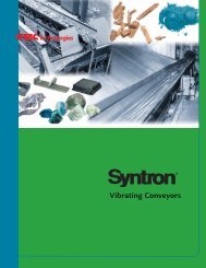
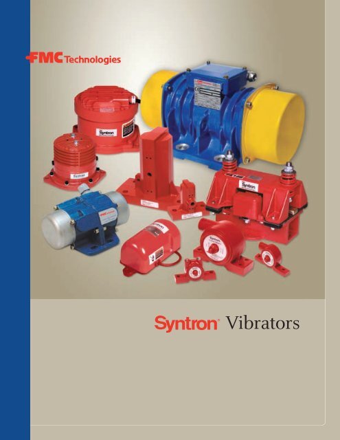
<strong>Vibrators</strong>
table of contents<br />
Syntron ® <strong>Vibrators</strong><br />
3<br />
Electromagnetic <strong>Vibrators</strong><br />
4<br />
Electric Rotary <strong>Vibrators</strong><br />
14<br />
Pneumatic <strong>Vibrators</strong><br />
32<br />
2
Syntron ® <strong>Vibrators</strong><br />
Syntron ® <strong>Vibrators</strong> offer an efficient, cost-effective<br />
means to maintain free flow of product from bins,<br />
hoppers and chutes, with a direct and positive result on<br />
the bottom line. Whether the need is to ensure constant,<br />
uninterrupted material flow, or to eliminate the necessity<br />
for manual manipulation of a bin, hopper or bulk<br />
material, Syntron <strong>Vibrators</strong> increase productivity and<br />
reduce production costs.<br />
Three types of Syntron <strong>Vibrators</strong> — electromagnetic,<br />
rotary electric and pneumatic — provide product flow<br />
solutions for just about any industry, application or<br />
environment. Compact yet mighty, Syntron <strong>Vibrators</strong> are<br />
designed for years of high-performance, trouble-free<br />
continuous or intermittent operation, with the broadest<br />
selection of models and power ranges available.<br />
Syntron Electromagnetic <strong>Vibrators</strong> are ideal<br />
for continuous or intermittent operation. An easily<br />
adjustable control assures optimum and variable<br />
material flow. Dependable Syntron Electromagnetic<br />
<strong>Vibrators</strong> are virtually maintenance-free because the<br />
electromagnetic design eliminates moving parts. Most<br />
models come standard with fully-enclosed dust-tight<br />
and watertight construction.<br />
Syntron Electric Rotary <strong>Vibrators</strong> are motor driven for<br />
reduced noise levels. These rugged vibrators are totally<br />
enclosed for reliable operation in dusty, dirty or moist<br />
environments. Adjustable eccentric weights allow easy<br />
adjustment of force to suit varying applications.<br />
Syntron Pneumatic <strong>Vibrators</strong> can be installed where<br />
electricity is not readily available because they use compressed<br />
air. Two types of pneumatic vibrators, turbine<br />
and piston, are available. Designed to keep operating<br />
noise at a minimum, Syntron Pneumatic Turbine<br />
<strong>Vibrators</strong> are ideal for locations where noise pollution is<br />
undesirable. Vibrator speed is adjusted by simply varying<br />
the air supply. Pneumatic turbine vibrators feature<br />
totally enclosed construction which eliminates concern<br />
over environmental factors such as dust, dirt or moisture.<br />
Syntron ® Electromagnetic <strong>Vibrators</strong><br />
Syntron ® Electric Rotary <strong>Vibrators</strong> by Visam<br />
Syntron ® Pneumatic <strong>Vibrators</strong><br />
Material Handling Solutions<br />
www.fmctechnologies.com/materialhandling<br />
3
Electromagnetic <strong>Vibrators</strong><br />
Syntron ® Electromagnetic <strong>Vibrators</strong><br />
Keep Your Materials Flowing Efficiently and Economically<br />
Syntron ® Electromagnetic<br />
<strong>Vibrators</strong> from <strong>FMC</strong> <strong>Technologies</strong><br />
offer an economical means of maintaining<br />
the flow of bulk materials<br />
from bins, hoppers and chutes. They<br />
come with an easily adjustable control<br />
which provides flexibility and<br />
assures optimum flow for the type of<br />
material being handled. Furthermore,<br />
Syntron Electromagnetic <strong>Vibrators</strong><br />
can be operated continuously or<br />
intermittently depending upon the<br />
specific requirements.<br />
To assure the highest standard of<br />
quality, Syntron Electromagnetic<br />
<strong>Vibrators</strong> are factory tested and<br />
adjusted for optimum performance.<br />
Most models come standard with<br />
totally enclosed, dust-tight and waterproof<br />
construction. Since these<br />
vibrators have no rotating or sliding<br />
parts, they are virtually maintenancefree.<br />
Syntron Electromagnetic <strong>Vibrators</strong><br />
come with the technical expertise of<br />
<strong>FMC</strong> <strong>Technologies</strong>’ application staff,<br />
who have been providing productive<br />
solutions for a wide variety of material<br />
handling problems for more than<br />
80 years. Call <strong>FMC</strong> <strong>Technologies</strong><br />
Application Specialists and request<br />
a data sheet or download one from<br />
our website at www.fmctechnologies.<br />
com/materialhandling. Syntron<br />
Electromagnetic <strong>Vibrators</strong> may also<br />
be ordered online at<br />
www.fmctechnologies.com/material<br />
handling.<br />
Syntron ® Electromagnetic <strong>Vibrators</strong> are available in a wide variety<br />
of sizes and force ratings.<br />
Features and Benefits<br />
■<br />
■<br />
■<br />
■<br />
■<br />
■<br />
■<br />
Electromagnetic design<br />
- No rotating or sliding parts; maintenance-free<br />
- Ideal for continuous or intermittent operation<br />
Adjustable control<br />
- Varies vibration force with simple turn of control knob<br />
Urethane encapsulated magnet assemblies<br />
- Provides protection from moisture and other contaminants<br />
- Prevents wire degradation<br />
Productivity enhancing performance<br />
- No need for manual labor to unclog bins or to<br />
keep material flowing<br />
Simple design, durable, rugged construction<br />
- Safe, reliable performance for years of service<br />
Wide range of sizes<br />
- Accommodates your specific application<br />
Low noise models available<br />
- Quiet, reliable operation<br />
4
Syntron ® model V-41 Electromagnetic<br />
Vibrator installed on a stainless steel bin.<br />
Syntron ® model V-20 Electromagnetic <strong>Vibrators</strong> maintain the<br />
flow of pasta from bins to packaging lines.<br />
This Syntron ® model V-85 Electromagnetic Vibrator is maintaining<br />
flow of dust particulates from the collecting hopper of an electrostatic<br />
precipitator.<br />
Material Handling Solutions<br />
www.fmctechnologies.com/materialhandling<br />
5
Electromagnetic <strong>Vibrators</strong><br />
Syntron ® Electromagnetic Vibrator Models<br />
Syntron ® V-2 and V-4 Electromagnetic <strong>Vibrators</strong> are two of the<br />
smallest industrial vibrators available. These versatile vibrators can be<br />
controlled electrically with a separate control. When these vibrators are<br />
operated without a control, they can be mechanically controlled by<br />
turning an easily accessible adjusting screw. Increased amplitude can be<br />
obtained by using rectified AC power. Flexibility and ease of installation<br />
are common to both models and the Model V-4 is available with a dusttight<br />
case.<br />
Models V-9 and V-20 are compact in size, but at 3600 vpm, they pack<br />
enough vibratory “punch” to excel in a wide range of applications. Each<br />
is available with a separate dust-tight case.<br />
Typical applications for the above models include installations on<br />
small bins, handling lightweight materials, or in counting, sorting or<br />
packaging operations.<br />
Impact and Cushioned Vibrator Compact Models<br />
Models V-50, V-85 and V-180 are “solid” impact vibrators. These units<br />
use a metal striking block to produce positive impact.<br />
Models V-41, V-51, V-86 and V-181 are “cushioned” impact vibrators,<br />
which utilize a rubber striking block to produce positive impact. Their<br />
high power/low noise characteristics make them ideal for use in confined<br />
areas with nearby workers. Physical dimensions and electrical specifications<br />
are identical to the “solid” impact type vibrators. Dust-tight and<br />
waterproof construction are standard for both versions.<br />
Open Models<br />
Models V-75 and V-500 feature a power-packed, solid impact, open-type<br />
design. They are used on difficult, heavy-duty applications. The V-500 is<br />
one of the largest magnetic vibrators available. Both the V-75 and V-500<br />
are available with a separate dust-tight case.<br />
Self-Contained Models<br />
Models V-9 through V-500 require separate controls unless specifically<br />
ordered as self-contained units. Self-contained units include a built-in<br />
rectifier and they always operate at full force. Self-contained units are<br />
recommended only where no force adjustment is required. Models V-41<br />
and V-500 are not available as self-contained units.<br />
V-2 V-4<br />
V-9, V-20<br />
V-41<br />
V-50<br />
V-51<br />
V-75<br />
V-85<br />
V-86<br />
V-180<br />
V-181<br />
V-500<br />
6
Selecting the Proper Syntron ® Electromagnetic Vibrator<br />
The primary consideration in<br />
vibrator selection is the thickness<br />
of the bin or chute wall. Once the<br />
proper vibrator model has been<br />
selected from the Application<br />
Tabulation Table, compare the<br />
capacity in the tapered portion of<br />
the bin with the rated capacity<br />
shown in the table. If the rated<br />
capacity is exceeded, multiple<br />
vibrators may be required, depending<br />
on the material being handled.<br />
Stiffeners used to reinforce the bin<br />
or chute may also affect the selection<br />
or preferred location of the<br />
vibrator. Please contact <strong>FMC</strong><br />
<strong>Technologies</strong> for a copy of our<br />
data sheet and assistance with<br />
selection of appropriate units in<br />
these applications.<br />
Syntron ® model V-20 Electromagnetic Vibrator ensures controlled feed<br />
from hopper to extruder.<br />
Application Tabulation<br />
No. <strong>Vibrators</strong> Needed per<br />
Model Wall Thickness* Capacity in Tapered Portion of Bin/Hopper<br />
V-2 24 ga (0.5 mm) 1 ft 3 (0.03 m 3 )<br />
V-4 22 ga (0.8 mm) 1 ft 3 (0.03 m 3 )<br />
V-9 20 ga (1 mm) 3 ft 3 (0.08 m 3 )<br />
V-20 1 ⁄16 in (1.5 mm) 10 ft 3 (0.28 m 3 )<br />
V-41 1 ⁄8 in (3 mm) 20 ft 3 (0.57 m 3 )<br />
V-51 1 ⁄8 in (3 mm) 30 ft 3 (0.85 m 3 )<br />
V-50 1 ⁄4 in (6 mm) 1 per 5-ton (4.5 metric ton)<br />
V-86 1 ⁄4 in (6 mm) 1 per 5-ton (4.5 metric ton)<br />
V-75 5 ⁄16 in (8 mm) 1 per 20-ton (18.1 metric ton)<br />
V-85 5 ⁄16 in (8 mm) 1 per 20-ton (18.1 metric ton)<br />
V-181 5 ⁄16 in (8 mm) 1 per 30-ton (27.2 metric ton)<br />
V-180 3 ⁄8 in (10 mm) 1 per 50-ton (45.4 metric ton)<br />
V-500 1 in (25 mm) 1 per 100-ton (90.7 metric ton)<br />
* Wall thickness is critical to proper vibrator selection; if in doubt, call <strong>FMC</strong><br />
<strong>Technologies</strong> for assistance.<br />
Material Handling Solutions<br />
7<br />
www.fmctechnologies.com/materialhandling
Electromagnetic <strong>Vibrators</strong><br />
Electromagnetic Vibrator Specifications and Dimensions<br />
V-2<br />
A<br />
Dia<br />
Specifications<br />
Speed (vpm 50 Hz)<br />
Speed (vpm 60 Hz)<br />
B<br />
C<br />
Weight Input Amps Without AC RC Without AC RC<br />
Model lb kg 115V 230V Control Control Control Control Control Control<br />
E<br />
D Dia. 1 Hole<br />
V-2 2 1 /2 1.1 0.3 0.18 6,000 6,000 3,000 7,200 7,200 3,600<br />
V-4<br />
V-4 4 1 /2 2.0 o.9 0.45 6,000 6,000 3,000 7,200 7,200 3,600<br />
Dimensions<br />
A B C D E F<br />
Model in mm in mm in mm in mm in mm in mm<br />
V-2 2 7 /8 73 2 1 /4 57 3 1 /16 78 13 /32 10 2 3 /8 60 -- --<br />
V-4 5 5 /8 143 1 1 /4 32 3 76 3 3 /4 95 17 /32 13 1 /2 13<br />
V-9, V-20<br />
Specifications<br />
Weight Input Amps Speed<br />
Model lb kg 115V 230V 460V (vpm 50 Hz) (vpm 60 Hz)<br />
V-9 9 1 /2 4.3 1.2 0.75 NA 3,000 3,600<br />
V-20 14 6.4 2.0 1.0 0.5 3,000 3,600<br />
Dimensions<br />
A B C D E F G<br />
Model in mm in mm in mm in mm in mm in mm in mm<br />
V-9 10 1 /4 260 9 1 /4 235 8 203 4 1 /4 108 4 1 /16 103 9 /16 14 7 /16 11<br />
V-20 10 1 /4 260 9 1 /4 235 8 203 5 1 /8 130 4 5 /16 110 1 /2 13 7 /16 11<br />
V-41<br />
Specifications<br />
Weight Input Amps Speed<br />
Model lb kg 115V 230V 460V (vpm 50 Hz) (vpm 60 Hz)<br />
V-41 25 11.3 3.5 1.75 0.88 3,000 3,600<br />
Dimensions<br />
A B C D E F G<br />
Model in mm in mm in mm in mm in mm in mm in mm<br />
V-41 6 1 /4 159 6 1 /2 165 7 /16 11 9 3 /8 238 8 1 /4 210 7 3 /8 187 17 /32 13<br />
V-50, V-51<br />
Specifications<br />
Weight Input Amps Speed<br />
Model lb kg 115V 230V 460V (vpm 50 Hz) (vpm 60 Hz)<br />
V-50, V-51 40 18.1 4.5 2.3 1.2 3,000 3,600<br />
8<br />
Dimensions<br />
A B C D E F G<br />
Model in mm in mm in mm in mm in mm in mm in mm<br />
V-50 9 1 /2 241 7 1 /4 184 15 /16 24 10 3 /4 273 9 1 /4 235 9 3 /4 248 11 /16 17<br />
V-51 9 1 /2 241 7 1 /4 184 15 /16 24 10 3 /4 273 9 1 /4 235 9 3 /4 248 11 /16 17<br />
When ordering, specify 50 or 60 Hz operation. Refer to control information, page 10. For other voltage requirements, contact <strong>FMC</strong> <strong>Technologies</strong>.
V-85, V-86<br />
Specifications<br />
Weight Input Amps Speed<br />
Model lb kg 115V 230V 460V (vpm 50 Hz) (vpm 60 Hz)<br />
V-85, V-86 79 35.8 7.0 3.5 1.8 3,000 3,600<br />
Dimensions<br />
A B C D E F G H<br />
Model in mm in mm in mm in mm in mm in mm in mm in mm<br />
V-85 10 7 /16 265 8 3 /4 222 5<br />
/8 16 11 1 /2 292 10 254 10 5 /8 270 7 178 11 /16 17<br />
V-86 10 7 /16 265 8 3 /4 222 5<br />
/8 16 11 1 /2 292 10 254 10 5 /8 270 7 178 11 /16 17<br />
V-180<br />
Specifications<br />
Weight Input Amps Speed<br />
Model lb kg 230V 460V (vpm 50 Hz) (vpm 60 Hz)<br />
V-180, V-181 220 100 12.0 6.0 3,000 3,600<br />
Dimensions<br />
A B C D E F<br />
Model in mm in mm in mm in mm in mm in mm<br />
V-180 15 3 /16 386 11 279 11 /16 17 12 305 15 1 /4 387 13 /16 21<br />
V-181 15 3 /16 386 11 279 11 /16 17 12 305 15 1 /4 387 13 /16 21<br />
V-75<br />
V-41<br />
Specifications<br />
Weight Input Amps Speed<br />
Model lb kg 115V 230V 460V (vpm 50 Hz) (vpm 60 Hz)<br />
V-75 113 51 16.0 8.0 4.0 3,000 3,600<br />
Dimensions<br />
A B C D E F G H J K L<br />
Model in mm in mm in mm in mm in mm in mm in mm in mm in mm in mm in mm<br />
V-75 13 265 10 254 12 3 /8 314 1 /2 13 8 203 11 /16 17 6 1 /2 165 8 208 11 1 /2 292 13 330 3 /4 19<br />
V-500<br />
Specifications<br />
Weight Input Amps Speed<br />
Model lb kg 230V 460V (vpm 50 Hz) (vpm 60 Hz)<br />
V-500 700 318 35.0 17.5 3,000 3,600<br />
Dimensions<br />
A B C D E F G H J<br />
Model in mm in mm in mm in mm in mm in mm in mm in mm in mm<br />
V-500 25 3 /4 654 14 1 /2 368 23 3 /4 603 20 508 13 330 1 1 /8 29 14 356 11 1 /2 292 1 9 /16 40<br />
When ordering, specify 50 or 60 Hz operation. Refer to control information, page 10. For other voltage requirements, contact <strong>FMC</strong> <strong>Technologies</strong>.<br />
Material Handling Solutions<br />
www.fmctechnologies.com/materialhandling<br />
9
Electromagnetic <strong>Vibrators</strong><br />
Syntron ® Electromagnetic Vibrator Controls<br />
Syntron ® Electromagnetic <strong>Vibrators</strong> are normally<br />
furnished with controls. Control units include an<br />
operating switch, fuse and adjustable control to<br />
vary vibration force. Models V-9 through V-181<br />
(except model V-41) can be furnished with selfcontained<br />
rectifiers if force adjustments are not<br />
required. (Unless a self-contained vibrator is specified,<br />
a control is required for operation of Models V-9<br />
through V-500.) Control units are available for<br />
multiple vibrator applications. Control enclosures<br />
can also be furnished to meet special electrical<br />
standards. In addition to the standard controls listed<br />
below, <strong>FMC</strong> <strong>Technologies</strong> can provide control systems<br />
built to meet your requirements.<br />
Intermittent DC Signal Potentiometer Voltage Solid Soft<br />
Control Model Volts Amps Enclosure Contacts Input Type AC RC Regulation State Start<br />
Power Pulse AC 115 5 Nema 1 ● Manual ● ●<br />
CTRC-1-C 230 5 Nema 1 ● Manual ● ●<br />
Power Pulse WT 115<br />
230 5<br />
Nema 4 ● Manual ● ●<br />
115 12<br />
C-2 230 6 Dust-tight Manual ●<br />
460 3<br />
115 20<br />
C-3 230 10 Dust-tight Manual ●<br />
460 4.5<br />
115 28<br />
C-4 230 18 Dust-tight Manual ●<br />
460 9<br />
C-42 460 7.5 Dust-tight Manual ●<br />
C-5<br />
230<br />
460<br />
40<br />
20<br />
Dust-tight Manual ●<br />
115 60<br />
CRSDC-2 230 45 Nema 4 ● ● Min / Max ● ● ●<br />
460 25<br />
Conductor Series*<br />
Conductor 15 115 15 Nema 4 ● Max / Manual ● ● ● ●<br />
Conductor DC 15 115 15 Nema 4 ● ● Max / Manual ● ● ● ● ●<br />
Conductor 28 230 8 Nema 4 ● Max / Manual ● ● ● ●<br />
Conductor DC 28 230 8 Nema 4 ● ● Max / Manual ● ● ● ● ●<br />
Conductor 118 115 18/20 Nema 12 ● Max / Manual ● ● ● ● ●<br />
Conductor 218 230 18/20 Nema 12 ● Max / Manual ● ● ● ● ●<br />
Conductor DC 118 115 18/20 Nema 12 ● ● Max / Manual ● ● ● ● ●<br />
Conductor DC 218 230 18/20 Nema 12 ● ● Max / Manual ● ● ● ● ●<br />
* Conductor controls are also available in open chassis models for ease<br />
in mounting in your system controls.<br />
Note: Some open chassis models have reduced amperage capability.<br />
Contact <strong>FMC</strong> <strong>Technologies</strong> for details.<br />
● Standard in the model listed<br />
Note: Different power voltages available. Contact <strong>FMC</strong><br />
<strong>Technologies</strong> for more information.<br />
10
Power Pulse and CTRC-1-C Controls<br />
Power Pulse AC<br />
Power Pulse WT<br />
CTRC-1-C<br />
CRSDC-2C Model Control<br />
C Model Controls<br />
CRSDC-2C<br />
C-2 Control<br />
C-3 Control<br />
C-4 Control<br />
C-42 Control<br />
C-5 Control<br />
Conductor Controls - Enclosed and Open Chassis<br />
G Hole<br />
Dia.<br />
E<br />
B<br />
F<br />
A<br />
C<br />
Conductor 15 and 28<br />
Conductor DC 15 and DC 28<br />
Control Dimensions<br />
Conductor 118 and 218<br />
Conductor DC 118 and DC 218<br />
Conductor PE 118 and PE 218<br />
Conductor Open Chassis<br />
All Models<br />
Control A B C D E F G H J Weight<br />
Model in mm in mm in mm in mm in mm in mm in mm in mm in mm lbs kg<br />
Power Pulse AC 6 1 /4 159 3 3 /4 95 2 1 /32 52 2 7 /8 73 5 3 /4 146 1 7 /8 48 7 /32 5 3 /8 10 -- -- 1 1 /4 0.5<br />
Power Pulse WT 6 1 /4 159 3 3 /4 95 2 1 /32 52 2 7 /8 73 5 3 /4 146 1 7 /8 48 7 /32 5 3 /8 10 -- -- 1 1 /4 0.5<br />
CTRC-1-C 6 1 /4 159 3 3 /4 95 2 1 /32 52 2 7 /8 73 5 3 /4 146 1 7 /8 48 7 /32 5 3 /8 10 -- -- 1 1 /4 0.5<br />
CRSDC-2C 19 3 /4 502 19 3 /4 502 8 3 /4 222 9 3 /4 248 18 1 /2 470 20 1 /2 521 5 /16 8 -- -- -- -- 50 22.7<br />
C-2B 10 1 /8 257 12 1 /8 308 7 3 /4 197 8 3 /4 222 7 3 /4 197 13 3 /8 340 7 /16 11 1 /16 2 -- -- 18 1 /8 8.4<br />
C-3A 12 1 /8 308 18 1 /8 460 9 1 /4 235 11 3 /8 289 9 3 /4 248 19 3 /8 492 7 /16 11 1 /16 2 -- -- 33 1 /4 15<br />
C-4A 12 1 /8 308 18 1 /8 460 9 1 /4 235 11 3 /8 289 9 3 /4 248 19 3 /8 492 7 /16 11 1 /16 2 -- -- 32 1 /2 14.6<br />
C-42A 12 1 /8 308 18 1 /8 460 9 1 /4 235 10 1 /4 260 9 3 /4 248 19 3 /8 492 7 /16 11 1 /16 2 -- -- 32 1 /2 14.6<br />
C-5A 18 1 /8 460 22 1 /8 562 9 1 ⁄4 235 11 3 ⁄8 289 15 3 ⁄4 400 23 3 ⁄8 594 7 /16 11 1 /16 2 -- -- 52 1 /2 23.5<br />
Conductor Series<br />
15 and 28 Enc. 8 203 9 1 /2 242 4 3 /4 121 5 5 /8 143 6 1 /4 159 8 5 /8 219 5 /16 8 -- -- 8 203 7 3.18<br />
118 and 218 Enc. 8 203 10 254 4 3 /4 121 5 5 /8 143 6 1 /4 159 8 5 /8 219 5 /16 8 -- -- 8 203 8 3.63<br />
Open Chassis 3 3 /4 95 3 15 /16 99 3 76 -- -- 3 1 /4 83 3 1 /4 83 3 /16 5 -- -- -- -- 0.58 0.26<br />
Material Handling Solutions<br />
11<br />
www.fmctechnologies.com/materialhandling
Electromagnetic <strong>Vibrators</strong><br />
Mounting Syntron ® Electromagnetic <strong>Vibrators</strong><br />
Correct location of electromagnetic vibrators is of prime importance in obtaining maximum efficiency<br />
from the selected model. Note: Operate vibrators on hoppers only when the hopper is open to flow.<br />
Otherwise, vibration may pack the hopper contents.<br />
Curved Surfaces<br />
To mount a vibrator to a<br />
curved surface, select a bracket<br />
made from a channel section or a<br />
bent plate. A center gusset is<br />
required for all totally enclosed<br />
vibrators, and two blocks of sufficient<br />
height to contact the curved surface are<br />
required for Models V-75 and V-500. The selected<br />
gusset or blocks must be securely welded to the<br />
underside of the bracket and curved surface. This<br />
arrangement is required to stiffen the mounting and<br />
transmit vibrations directly to the hopper contents.<br />
Mounting bolt heads can be welded to the underside<br />
of the bracket.<br />
Rectangular Hoppers<br />
Mount vibrator and<br />
mounting channel as<br />
for a conical hopper or<br />
a curved surface. If a<br />
stiffener obstructs<br />
mounting, mount the<br />
vibrator in the middle<br />
of the panel next to the<br />
stiffener. If required, a<br />
second vibrator should<br />
be mounted on the<br />
opposite face at a slightly higher elevation.<br />
Hopper with Sloping<br />
Discharge<br />
Mount the vibrator on<br />
the center line of the hopper,<br />
as close to the discharge as<br />
possible. An additional<br />
vibrator may be required<br />
on the discharge chute.<br />
Note: Drawings illustrate typical installations. Specific installations may<br />
require slight variations. For other applications not covered here, please<br />
consult factory for recommendations.<br />
Rectangular or Cylindrical Bins with Flat<br />
Bottom and Center Discharge.<br />
Mount directly to the side of the<br />
bin, just below the point where the<br />
materials’ natural angle of repose<br />
intersects the side, as shown.<br />
Parabolic Bins or Hoppers<br />
Mount the vibrator within<br />
one foot of each discharge<br />
opening and in line with<br />
center of opening.<br />
Conical Hoppers<br />
Mount the vibrator to<br />
the hopper (as for a curved<br />
surface) 12 to 18 inches (300<br />
to 450 mm) or less from the<br />
discharge.<br />
Inclined Chutes<br />
Chutes less than 10 to 12 feet<br />
(3 to 3.6 m) long are usually<br />
equipped with just one vibrator<br />
located well below the center.<br />
Allow for the vibrator to be<br />
moved about one foot (300 mm)<br />
in either direction. On chutes<br />
requiring more than one<br />
vibrator, the first one should be located 18 to 24 inches<br />
(450 to 500 mm) from the outlet. The second unit<br />
should be mounted about half-way between the first<br />
vibrator and the upper end. Allow for the vibrators to<br />
be moved about one foot (300 mm) in either direction.<br />
12
Screw Feeder<br />
Screw conveyors feed from the back of the<br />
hopper. Vibrator should be 1/3 from the inlet. If two<br />
vibrators are used, place second vibrator on opposite<br />
side, 1/3 from the discharge. Do not operate the<br />
vibrator at the discharge end until the back of the<br />
bin is empty and the vibrator at the inlet is shut off.<br />
Belt Conveyor and Standard Bin<br />
Mount vibrator on the belt discharge side of the hopper.<br />
Follow mounting instructions for the appropriate bin type<br />
on page 12.<br />
Short Screw Feeder<br />
Place vibrator<br />
as close as possible<br />
to feeder.<br />
Concrete Hopper or Lined Wooden Hopper<br />
For wooden hoppers lined with thin sheet metal,<br />
attach vibrator mounting bolts to the hopper lining.<br />
For concrete hoppers, secure a steel plate across the<br />
top inside of the hopper, to the discharge opening<br />
along the side to which the vibrator will be mounted.<br />
At about one-quarter or less of the distance from the<br />
discharge to the vertical side, cut an opening to allow<br />
the vibrator to be bolted to the steel plate.<br />
Long Bin<br />
Belt conveyors feed from the front of the hopper.<br />
Vibrator should be 1/3 from front. If two vibrators<br />
are used, place one on the opposite side and 1/3<br />
from back. Do not operate the back vibrator until<br />
the front is empty and the front vibrator is shut off.<br />
Note: Drawings illustrate typical installations. Specific installations may<br />
require slight variations. For other applications not covered here, please<br />
consult factory for recommendations.<br />
Vibrating Feeder and Standard Bin<br />
Mount vibrator on the feeder<br />
infeed side of the hopper. Follow<br />
mounting instructions for the<br />
appropriate bin type on page 12.<br />
Material Handling Solutions<br />
13<br />
www.fmctechnologies.com/materialhandling
Electric Rotary <strong>Vibrators</strong><br />
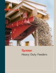
Syntron ® Electric Rotary <strong>Vibrators</strong> by Visam<br />
Rugged construction, reliable performance to assure the efficient flow<br />
of bulk materials<br />
Syntron ® Electric Rotary <strong>Vibrators</strong> from <strong>FMC</strong><br />
<strong>Technologies</strong> provide a safe, reliable, cost-effective<br />
way to maintain the flow of materials. Motor-driven<br />
to provide virtually noiseless operation (most models<br />
76 db or less*), these vibrators help facilitate material<br />
flow from the smallest bin, hopper or chute to the<br />
largest silo, screens, feeders, grizzly feeders, conveyors,<br />
fluid beds, shake-outs, helical elevators, etc.<br />
Additionally, they are totally enclosed to eliminate<br />
concerns over environmental factors such as dust,<br />
dirt and rain. Syntron Electric Rotary <strong>Vibrators</strong> can<br />
be used to pack material in drums and bags as well as<br />
to consolidate material in pipe and precast industries,<br />
in vibrating screen applications and many other<br />
industrial environments. High stroke/low frequency<br />
models are especially suitable for hard-to-handle<br />
materials such as sawdust, cinder or clay content<br />
materials.<br />
Syntron Electric Rotary Bin <strong>Vibrators</strong> also come<br />
with the technical expertise of <strong>FMC</strong> <strong>Technologies</strong>'<br />
application staff, who have been providing productive<br />
solutions for a wide variety of material handling<br />
problems for more than 80 years.<br />
* At 3 feet (1 meter) on A scale<br />
Electric Rotary <strong>Vibrators</strong> in Primary Feeder<br />
Application<br />
Features and Benefits<br />
■ Motor driven for reduced noise level<br />
■ High force to weight ratio<br />
■ Adjustable eccentric weights allow easy change of force<br />
to suit varying applications<br />
■ Orbital action facilitates material flow in hopper &<br />
chute applications<br />
■ Terminal box for easy connection and change of voltage<br />
(on 3 phase models) or direction of rotation<br />
■ Units sealed to IP66 except the AMV which is IP65<br />
■ Rugged, durable construction for many years with safe,<br />
reliable performance<br />
■ Wide range of sizes to accommodate your specific<br />
application<br />
■ Class F (Inverter Duty) windings are standard<br />
■ All units are tropical duty for high humidity applications /<br />
locations<br />
■ Standard construction suitable for operation in -22 to<br />
+133 degree F ambient temperature locations<br />
■ Internal thermal detection is standard on larger units<br />
■ Each vibrator fully tested after assembly<br />
■ All units are designed for heavy and continuous duty at<br />
the maximum centrifugal force<br />
■ Wide range with centrifugal forces up to 50,000 lbs<br />
14
Selecting the Proper Syntron ® Electric Rotary Vibrator<br />
for Rotational and Elliptical Applications<br />
Bins or Hoppers<br />
In order to move material in a bin or hopper, the<br />
friction between the material and the bin wall must<br />
be broken. Once the friction is broken, the material<br />
cannot cling to the sides of the bin and it will flow<br />
out through the discharge. For most applications, the<br />
vibrator force needed to accomplish this is simply<br />
calculated as follows:<br />
■<br />
■<br />
■<br />
Calculate the weight of the material in the transition or<br />
sloping part of the bin. Normally, this is the only place<br />
where the friction between the material and the bin side<br />
has to be broken. Do not calculate the total weight, only<br />
what is in the transition part of the bin.<br />
For conical bins, calculate as follows:<br />
.261 x dia. 2 x height x material density in lb/ft 3 (kg/m 3 )<br />
For rectangular bins, calculate as follows:<br />
Length x width x height x 1/3 x material density.<br />
When the weight (lb) has been calculated, divide<br />
the weight by 10 to get the force or impact needed<br />
from the vibrator (lbf). For example: The conical part<br />
of a 25-ton bin contains 7000 lb Divide 7,000 by 10<br />
to get the force (lbf) or impact needed from the<br />
vibrator. Find a suitable vibrator on pages 20 - 29.<br />
Additional considerations when sizing vibrators<br />
to bins:<br />
■<br />
■<br />
■<br />
■<br />
If the bin side angle is less than 30 degrees, select a<br />
larger vibrator.<br />
If the bin has a vertical section, select a larger vibrator.<br />
If the bin wall is extra thick select a larger vibrator.<br />
On very sticky and hard to move materials, it is better to<br />
use two small vibrators instead of one large one (size the<br />
two smaller ones by dividing the required force in half).<br />
Vibrating Tables for Packing Materials<br />
Dense materials respond best to high-frequency<br />
vibration (3600 rpm or more), while light, fluffy or<br />
flaky materials respond best to low-frequency<br />
vibration (1800 rpm or less).<br />
ROTATIONAL<br />
obtained with<br />
1 Electric Vibrator<br />
ELLIPTICAL<br />
obtained with<br />
1 Electric Vibrator<br />
(not in center of gravity)<br />
For packing or settling materials, use a vibrator<br />
with an impact force of one-and-a-half to two times<br />
larger than the weight of the material plus container.<br />
Find a suitable vibrator in the tables on pages 20 - 29.<br />
Vibrating Screens<br />
For self-cleaning screen, use a vibrator with a<br />
centrifugal force (impact) four times the weight of<br />
the material plus the weight of the screen.<br />
Note: Coarse, lumpy, sticky or wet materials<br />
respond best to high-frequency vibration; powdery<br />
and dry materials to low-frequency vibration.<br />
Consolidating Concrete<br />
For three-inch “slump” concrete, use a vibrator<br />
with the same force (impact) as the weight of concrete<br />
and form. For one- to two-inch slump concrete, an<br />
additional 30 to 50 percent impact is needed. For<br />
dry mixes (zero slump) increase the impact by 100<br />
to 200 percent.<br />
Chutes<br />
The force required of the vibrator is equal to<br />
the weight of the chute plus the vibrator plus the<br />
maximum material in the chute. See page 30 for<br />
more information.<br />
15<br />
Material Handling Solutions<br />
www.fmctechnologies.com/materialhandling
Electric Rotary <strong>Vibrators</strong><br />
Selecting the Proper Electric Rotary Vibrator<br />
for Linear Applications<br />
<strong>FMC</strong> <strong>Technologies</strong> now offers vibrators for a broader<br />
range of equipment applications by introducing the<br />
Visam product line in combination with the years of<br />
experience, service and knowledge of Syntron vibratory<br />
products. Our products have been associated with<br />
process control in conveying, feeding and screening<br />
applications for over 80 years. Markets include:<br />
LINEAR<br />
obtained with<br />
2 identical Electric <strong>Vibrators</strong><br />
(opposite rotation)<br />
■<br />
■<br />
■<br />
■<br />
■<br />
■<br />
■<br />
■<br />
■<br />
■<br />
Mining<br />
Steel<br />
Cement<br />
Aggregate<br />
Foundry<br />
Chemical<br />
Recycling<br />
Plastics<br />
Food<br />
Packaging<br />
Custom equipment applications for<br />
Linear Vibration include:<br />
■<br />
Horizontal Screens<br />
■<br />
Shake Out<br />
■<br />
Feeders<br />
■<br />
Fluid Beds<br />
■<br />
Grizzly Feeders<br />
■<br />
Purifiers<br />
■<br />
■<br />
Conveyors<br />
Hopper Feeders<br />
■<br />
■<br />
Spiral Elevator<br />
Separators (milling)<br />
Feeder for use in Steel Foundry.<br />
16
Steel Foundry Steel Foundry Steel Foundry<br />
Food Industry Food Industry Chemical / Plastic<br />
Mining / Aggregates Mining / Aggregates Mining / Aggregates<br />
Mining / Aggregates Cement Ceramic<br />
Material Handling Solutions<br />
www.fmctechnologies.com/materialhandling<br />
17
Electric Rotary <strong>Vibrators</strong><br />
Vibrator Selection Guide<br />
Choosing the right type of vibrator when conveying material<br />
For maximum efficiency proper vibrator selection<br />
is the key. Selection requires information regarding<br />
your process considering the key requirements below:<br />
■<br />
■<br />
Process (such as conveying, screening, hopper feeding,<br />
primary feeding, or feeding)<br />
Particle size of the material<br />
■ Line power frequency / Hz (50 or 60)<br />
■<br />
Weight of vibrating structure<br />
Process Typical Speeds Typical Angles<br />
(RPM)<br />
Line of Force<br />
50 Hz 60 Hz<br />
(°)<br />
Product of high specific weight and medium/large size (i.e. rock)<br />
Primary Feeding 750 - 1,000 900 - 1,200 30 - 40<br />
Primary Scalping 750 - 1,000 900 - 1,200 30 - 45<br />
Product of high specific weight and coarse particles (i.e. gravel)<br />
Primary Screening 1,000 - 1,500 900 - 1,800 30 - 45<br />
Hopper Feeding 1,000 - 1,500 1,200 - 1,800 25 - 30<br />
Feeding 1,000 - 1,500 1,200 - 1,800 25 - 35<br />
Product of high specific weight and fine particles (i.e. sand)<br />
Fine Screening 1,500 1,200 - 1,800 30 - 45<br />
Hopper Feeding 1,000 - 1,500 1,200 - 1,800 25 - 35<br />
Feeding 1,000 - 1,500 1,200 - 1,800 25 - 35<br />
Dewatering 1,000 - 1,500 1,200 - 1,800 30 - 50<br />
Fluidizing 750 - 1,000 720 - 900 50 - 80<br />
Product of low specific weight and very flexible (i.e. leaves)<br />
Conveying 750 - 1,000 720 - 900 25 - 30<br />
Product of low specific weight and coarse particles (i.e. wheat)<br />
Separating 1,000 900 - 1,200 30 - 45<br />
18
Basic Formula<br />
FORMULA<br />
e = S / 2 SM t = W t x e W t = W s + W v a = CF t / W t<br />
e = SM t / W t S = e x 2 CF t = W t x a<br />
LEGEND<br />
e = Eccentricity (in.)<br />
s = Total Stroke (Peak to Peak) (in.)<br />
a = Acceleration (Number of G’s)<br />
SM t = Total Static Moment (Static Moment of vibrator x number of vibrators) (lb*in)<br />
CF t = Total Centrifugal Force (Centrifugal Force of vibrator x number of vibrators) (lb)<br />
W t = Total Weight of machine (structure + vibrators) (lb)<br />
W s = Weight of isolated structure (lb)<br />
W v = Weight of vibrator (Weight of vibrator x number of vibrators) (lb)<br />
SMv = Static Moment of vibrator (lb*in)<br />
Speed and Stroke<br />
MAX<br />
STROKE<br />
Hz POLE SPEED at 5 G’S<br />
50 8 750 .60 in.<br />
60 8 900 .43 in.<br />
50 6 1,000 .35 in.<br />
60 6 1,200 .26 in.<br />
50 4 1,500 .18 in.<br />
60 4 1,800 .12 in.<br />
50 2, AMV 3,000 .05 in.<br />
60 2, AMV 3,600 .04 in.<br />
* As a general rule it is advisable to limit designs for a maximum<br />
of 5 G’s of acceleration. In specialized applications or designs it<br />
may be acceptable to exceed the 5 G acceleration limit. Consult<br />
factory for guidelines.<br />
Example:<br />
Known information:<br />
Type of process = quarry primary feeder Stroke (from table) = .26<br />
Type of vibration = linear (2 vibrators) Speed (from table) = 1,200 RPM<br />
Weight of vibrating structure = 3,300 lb Power Supply = 60 Hz<br />
Estimated vibrator’s weight: = 825 lb (25% of vibrating<br />
structure)<br />
Vibrator rough selection:<br />
I. Considering the known information from above use the table on page 18 to determine rough Speed (RPM) needed.<br />
(In the example above the RPM range is 900 - 1,200 for a Primary Feeding process at 60Hz.)<br />
II. Using the Speed and Stroke table above, select the appropriate vibrator pole size based on your Hz and Speed<br />
requirements. (In the example above the pole selection is 6 based on 60Hz and 1,200 Speed (RPM).)<br />
III. Using the formulas below, determine SM v (Static Moment) required for this application.<br />
a. e = S / 2 = > .26 / 2 = .13 in<br />
b. SM t = W t x e = > (3300 + 825) x .13 = 536<br />
c. SM v = SM t / Number of <strong>Vibrators</strong> = > 536 / 2 = 268 lb*in<br />
IV. Referencing the charts on pages 20 - 29 the <strong>FMC</strong> model number selection is SPV6-14000 based on 6 pole, 60Hz and a Static<br />
Moment of 268 or greater. (Actual Static Moment for this vibrator is 319.7)<br />
Checking the <strong>FMC</strong> model selection:<br />
SM t = SM v x 2 = 319 (actual SM v from page 26) x 2 = 638 lb*in<br />
W t = W s + W v = 3300 + (477 (actual wt from page 26) x 2) = 4254.0 lb<br />
e = SM t / W t = 638 / 4254 = .15 in<br />
* In the example above by using two SPV6-14000 vibrators, the desired eccentricity 0.13 can be reached with 87% setting of weights (SMt 638 x 87% = 555/4254 = .13 in).<br />
* If additional adjustments are required, the following larger model SPV6-15000 can be selected, recalculating the eccentricity formula to reach 81% of weight setting.<br />
* When selecting a vibrator it is always advisable to use approximately 80% of the Static Moment or Centrifugal Force reported in the catalog in order to leave<br />
20% of extra performance available in case on site adjustments are required. According to this assumption all our vibrators are set at 80% before shipment.<br />
Material Handling Solutions<br />
www.fmctechnologies.com/materialhandling<br />
19
Electric Rotary <strong>Vibrators</strong><br />
AMV Electric Rotary Vibrator<br />
Specifications and Dimensions<br />
<strong>FMC</strong> <strong>FMC</strong> Description Weight (lbs) Centrifugal Force (lbs) Static Moment (lb*in) RPM Amps<br />
Model Part Number 50Hz 60Hz 50Hz 60Hz 50Hz 60Hz 50Hz 60Hz 50Hz 60Hz<br />
4 BOLT<br />
AMV1-70BN 6515-040-BN 110 - 120V 60hz Single Phase 3 3/4 3 3/4 – 68 0.18 0.18 – 3,600 – 0.26<br />
AMV1-70BM 6515-040-BM 220 - 240V 60hz Single Phase 3 3/4 3 3/4 – 68 0.18 0.18 – 3,600 – 0.13<br />
AMV2-70BO 6515-040-BO 440 - 460V 60hz 3-Phase 3 3/4 3 3/4 – 68 0.18 0.18 – 3,600 – 0.07<br />
AMV1-50AM 6515-040-AM 220 - 240V 50hz Single Phase 3 3/4 3 3/4 47 – 0.18 0.18 3,000 – 0.11 –<br />
AMV2-50AQ 6515-040-AQ 380 - 415V 50hz 3-Phase 3 3/4 3 3/4 47 – 0.18 0.18 3,000 – 0.06 –<br />
4 BOLT MOUNTING<br />
20
SPV Electric Rotary Vibrator<br />
Specifications and Dimensions<br />
3,000 RPM, 50Hz<br />
3,600 RPM, 60Hz<br />
2-Pole<br />
*COMPLETE THE PART NUMBERS /<br />
MODEL NUMBERS FOUND IN THE SPECIFICATIONS<br />
CHART BY ADDING A POWER INPUT SUFFIX:<br />
POWER INPUT - SINGLE PHASE VIBRATORS<br />
Suffix Description<br />
BN 110 - 120V 60Hz Single Phase<br />
BM 220 - 240V 60Hz Single Phase<br />
AM 220 - 240V 50Hz Single Phase<br />
Specifications<br />
FRAME <strong>FMC</strong> <strong>FMC</strong> Weight (lbs) Centrifugal Force (lbs) Static Moment (lb*in) Max Input Power (kw) Max Current Amps<br />
SIZE Model Part Number 50Hz 60Hz 50Hz 60Hz 50Hz 60Hz 50Hz 60Hz 50Hz 60Hz<br />
4 BOLT<br />
220V 110V<br />
SPV1 020 SPV1-300* 6515-031-020* 11 10 276 298 1.1 0.8 0.17 0.18 0.80 1.60<br />
SERIES, 021 SPV1-500* 6515-031-021* 11 11 483 496 1.9 1.3 0.18 0.19 0.80 1.70<br />
2-POLE<br />
030 SPV1-700* 6515-031-030* 19 19 741 710 2.9 1.9 0.30 0.33 1.40 3.00<br />
SINGLE<br />
PHASE 040 SPV1-1300* 6515-031-040* 34 32 1,091 1,257 4.3 3.4 0.50 0.75 3.10 7.80<br />
050 SPV1-1900* 6515-031-050* 47 45 1,746 1,887 6.8 5.1 0.65 1.00 5.70 9.60<br />
060 SPV1-2200* 6515-031-060* 58 56 2,218 2,127 8.7 5.8 1.00 0.90 4.70 8.10<br />
061 SPV1-2700* 6515-031-061* 62 59 2,956 2,661 11.6 7.2 1.25 1.25 5.90 11.00<br />
<strong>FMC</strong><br />
OVERALL REFERENCE DIMENSIONS (inches)<br />
Model “A” “B” “C” “D” “E” “F” “G” “H” “I” “L” “M” “N” “P” “Q” “R”<br />
.<br />
4 BOLT<br />
SPV1-300* 9 - 1/4 5 - 7/8 5 - 5/8 4 - 1/8 2 - 7/16 5 - 1/8 1 - 7/8 0.354 2.32 - 2.95 4.17 1/2 3 - 7/8 1 - 3/16 1 - 3/8 M16X1.5<br />
SPV1-500* 9 - 1/4 5 - 7/8 5 - 5/8 4 - 1/8 2 - 7/16 5 - 1/8 1 - 7/8 0.354 2.32 - 2.95 4.17 1/2 3 - 7/8 1 - 3/16 1 - 3/8 M16X1.5<br />
SPV1-700* 10 - 3/8 6 - 5/16 6 - 7/8 4 - 15/16 2 - 13/16 5 - 1/2 1 - 9/16 0.512 3.54 4.92 9/16 5 - 1/4 1 - 5/8 1 - 3/16 M16X1.5<br />
SPV1-1300* 12 7 - 1/2 8 - 1/16 5 - 13/16 3 - 3/8 6 - 7/16 2 0.512 3.94 6.10 11/16 6 - 11/16 1 - 15/16 1 - 1/2 M20X1.5<br />
SPV1-900* 13 - 11/16 8 - 3/8 8 - 7/16 6 - 5/8 3 - 3/4 7 - 1/4 2 - 3/8 0.669 4.53 6.69 13/16 7 - 1/2 2 - 5/16 1 - 3/4 M20X1.5<br />
SPV1-2200* 14 - 13/16 9 - 3/16 9 - 1/4 7 - 3/8 4 - 1/8 7 - 7/8 2 - 11/16 0.669 4.72 7.09 13/16 7 - 9/16 2 - 5/16 1 - 11/16 M20X1.5<br />
SPV1-2700* 14 - 13/16 9 - 3/16 9 - 1/4 7 - 3/8 4 - 1/8 7 - 7/8 2 - 11/16 0.669 4.72 7.09 13/16 7 - 9/16 2 - 5/16 1 - 11/16 M20X1.5<br />
4 BOLT MOUNTING<br />
Sizes up to and including SPV1-1300 feature permanently lubricated bearings.<br />
Sizes up to and including SPV1-2200 feature an aluminum housing.<br />
Sizes up to and including SPV1-1900 and larger use logarithmic roller type bearings.<br />
Material Handling Solutions<br />
www.fmctechnologies.com/materialhandling<br />
21
Electric Rotary <strong>Vibrators</strong><br />
SPV Electric Rotary Vibrator<br />
Specifications and Dimensions<br />
*COMPLETE THE PART NUMBERS / MODEL NUMBERS FOUND IN<br />
THE SPECIFICATIONS CHART BY ADDING A POWER INPUT SUFFIX:<br />
POWER INPUT - 3-PHASE VIBRATORS<br />
Suffix Description<br />
BB 220 - 240/440 - 480V 60Hz 3-Phase<br />
AA 220 - 240/380 - 415V 50Hz 3-Phase<br />
BY 575 - 600V 60Hz 3-Phase<br />
3,000 RPM, 50Hz<br />
3,600 RPM, 60Hz<br />
2-Pole<br />
Specifications<br />
SPV2<br />
SERIES,<br />
2-POLE<br />
3-<br />
PHASE<br />
FRAME <strong>FMC</strong> <strong>FMC</strong> Weight (lbs) Centrifugal Force (lbs) Static Moment (lb*in) Max Input Power (kw) Max Current Amps<br />
SIZE Model Part Number 50Hz 60Hz 50Hz 60Hz 50Hz 60Hz 50Hz 60Hz 50Hz 60Hz<br />
4 BOLT<br />
400V 460V<br />
020 SPV2-300* 6515-032-020* 11 10 276 298 1.1 0.8 0.18 0.20 0.40 0.30<br />
021 SPV2-500* 6515-032-021* 11 11 483 496 1.9 1.3 0.19 0.21 0.40 0.40<br />
030 SPV2-700* 6515-032-030* 19 19 741 710 2.9 1.9 0.28 0.30 0.60 0.60<br />
040 SPV2-1300* 6515-032-040* 34 32 1,091 1,257 4.3 3.4 0.51 0.60 1.00 1.00<br />
050 SPV2-1900* 6515-032-050* 47 45 1,746 1,887 6.8 5.1 0.70 0.73 1.20 1.10<br />
060 SPV2-2200* 6515-032-060* 58 56 2,218 2,127 8.7 5.8 1.06 1.20 1.80 1.80<br />
061 SPV2-2700* 6515-032-061* 62 59 2,956 2,661 11.6 7.2 1.30 1.40 2.10 2.00<br />
070 SPV2-4300* 6515-032-070* 100 95 4,065 4,257 15.9 11.6 1.55 1.60 2.70 2.80<br />
080 SPX2-4900* 6515-032-080* 97 93 4,410 4,851 17.3 13.2 1.70 1.80 2.80 2.50<br />
090 SPX2-6400* 6515-032-090* 120 116 5,954 6,395 23.3 17.4 2.00 2.20 3.20 3.20<br />
100 SPV2-11000* 6515-032-100* 236 233 8,971 10,860 35.1 29.5 4.00 4.20 6.30 6.00<br />
110 SPV2-13000* 6515-032-110* 338 333 12,432 12,527 48.6 34.0 5.50 5.80 8.60 7.90<br />
FRAME <strong>FMC</strong> <strong>FMC</strong> Weight (lbs) Centrifugal Force (lbs) Static Moment (lb*in) Max Input Power (kw) Max Current Amps<br />
SIZE Model Part Number 50Hz 60Hz 50Hz 60Hz 50Hz 60Hz 50Hz 60Hz 50Hz 60Hz<br />
6 BOLT<br />
400V 460V<br />
120 SPV2-15000* 6515-032-120* 395 386 15,051 14,334 58.9 39.0 7.00 7.30 11.20 10.20<br />
129 SPV2-18000* 6515-032-129* 497 490 17,170 17,562 67.2 47.7 7.90 8.60 13.50 12.00<br />
130 SPV2-21000* 6515-032-130* 545 536 21,089 20,779 82.5 56.5 8.00 9.50 13.00 13.50<br />
Sizes up to and including SPV2-1300 feature permanently lubricated bearings.<br />
Sizes up to and including SPV2-2200 feature an aluminum housing.<br />
Sizes SPX2-4900 and larger feature cast iron housing.<br />
Sizes SPV2-1900 and larger feature logarithmic roller type bearings.<br />
22
4 BOLT MOUNTING<br />
(Frame Sizes 20-110)<br />
6 BOLT MOUNTING<br />
(Frame Sizes 120-130)<br />
OVERALL REFERENCE DIMENSIONS (inches)<br />
“A” “B” “C” “D” “E” “F” “G” “H” “I” “L” “M” “N” “P” “Q” “R”<br />
4 BOLT<br />
8 - 3/8 5 - 7/8 5 - 5/8 4 - 1/8 2 - 7/16 5 - 1/8 1 - 13/16 0.354 2.44 - 2.91 4.17 1/2 3 - 7/8 1 - 3/16 1 - 3/8 M16X1.5<br />
9 - 1/4 5 - 7/8 5 - 5/8 4 - 1/8 2 - 7/16 5 - 1/8 1 - 13/16 0.354 2.44 - 2.91 4.17 1/2 3 - 7/8 1 - 3/16 1 - 3/8 M16X1.5<br />
13 - 1/8 6 - 5/16 6 - 7/8 4 - 15/16 2 - 13/16 5 - 1/2 1 - 9/16 0.512 3.54 4.92 9/16 5 - 1/4 1 - 5/8 1 - 3/16 M16X1.5<br />
12 7 - 1/2 8 - 1/16 5 - 13/16 3 - 3/8 6 - 7/16 2 0.512 3.94 6.10 11/16 6 - 11/16 1 - 15/16 1 - 1/2 M20X1.5<br />
13 - 11/16 8 - 3/8 8 - 7/16 6 - 5/8 3 - 3/4 7 - 1/4 2 - 3/8 0.669 4.53 6.69 13/16 7 - 1/2 2 - 5/16 1 - 3/4 M20X1.5<br />
14 - 13/16 9 - 3/16 9 - 1/4 7 - 3/8 4 - 1/8 7 - 7/8 2 - 11/16 0.669 4.72 7.09 13/16 7 - 9/16 2 - 5/16 1 - 11/16 M20X1.5<br />
14 - 13/16 9 - 3/16 9 - 1/4 7 - 3/8 4 - 1/8 7 - 7/8 2 - 11/16 0.669 4.72 7.09 13/16 7 - 9/16 2 - 5/16 1 - 11/16 M20X1.5<br />
16 - 5/16 9 - 5/8 9 - 3/4 7 - 7/8 4 - 7/16 8 - 7/16 3 - 1/4 0.669 5.91 7.48 1 8 - 1/4 2 - 1/16 1 - 15/16 M20X1.5<br />
16 - 1/8 11 10 - 3/16 8 - 3/8 4 - 5/8 8 - 15/16 2 - 7/8 0.669 6.30 7.87 1 - 3/16 10 3 - 3/8 3 M20X1.5<br />
20 - 3/16 11 - 13/16 11 9 - 5/16 5 - 3/16 10 - 1/16 4 - 1/8 0.866 6.50 9.06 1 - 3/8 11 - 11/16 4 - 5/16 2 - 13/16 M20X1.5<br />
22 - 3/4 13 - 1/4 13 - 3/8 10 - 5/8 5 - 7/8 11 - 1/4 4 - 5/16 0.984 6.50 10.63 1 - 9/16 11 - 1/8 3 - 1/2 2 - 3/8 M25X1.5<br />
24 - 1/2 14 - 1/4 14 - 3/8 12 - 1/8 6 - 9/16 12 - 11/16 4 - 9/16 1.142 8.27 11.61 1 - 9/16 12 3 - 7/16 2 - 1/2 M25X1.5<br />
OVERALL REFERENCE DIMENSIONS (inches)<br />
“A” “B” “C” “D” “E” “F” “G” “H” “I” “L” “M” “N” “P” “Q” “R”<br />
6 BOLT<br />
26 - 3/16 15 - 3/8 15 - 7/16 13 - 9/16 7 - 9/16 15 - 9/16 4 - 7/8 1.142 4.33 12.20 1 - 9/16 12 - 15/16 3 - 11/16 3 - 3/16 M25X1.5<br />
27 - 5/16 15 - 3/8 16 - 11/16 13 - 9/16 8 15 - 9/16 4 - 7/8 1.142 4.53 12.60 1 - 3/4 13 - 11/16 3 - 7/8 2 - 5/8 M25X1.5<br />
28 - 5/16 15 - 3/8 16 - 11/16 13 - 9/16 8 15 - 9/16 4 - 7/8 1.142 4.53 12.60 1 - 3/4 13 - 11/16 3 - 7/8 2 - 5/8 M25X1.5<br />
Material Handling Solutions<br />
www.fmctechnologies.com/materialhandling<br />
23
Electric Rotary <strong>Vibrators</strong><br />
SPV Electric Rotary Vibrator<br />
Specifications and Dimensions<br />
1,500 RPM, 50Hz<br />
1,800 RPM, 60Hz<br />
4-Pole<br />
*COMPLETE THE PART NUMBERS / MODEL NUMBERS FOUND IN<br />
THE SPECIFICATIONS CHART BY ADDING A POWER INPUT SUFFIX:<br />
POWER INPUT - 3-PHASE VIBRATORS<br />
Suffix Description<br />
BB 220 - 240/440 - 480V 60Hz 3-Phase<br />
AA 220 - 240/380 - 415V 50Hz 3-Phase<br />
BY 575 - 600V 60Hz 3-Phase<br />
Specifications<br />
FRAME <strong>FMC</strong> <strong>FMC</strong> Weight (lbs) Centrifugal Force (lbs) Static Moment (lb*in) Max Input Power (kw) Max Current Amps<br />
SIZE Model Part Number 50Hz 60Hz 50Hz 60Hz 50Hz 60Hz 50Hz 60Hz 50Hz 60Hz<br />
4 BOLT<br />
400V 460V<br />
020 SPV4-150* 6515-034-020* 12 12 121 148 1.9 1.6 0.09 0.10 0.30 0.20<br />
021 SPV4-200* 6515-034-021* 13 13 190 198 3.0 2.2 0.10 0.15 0.30 0.30<br />
030 SPV4-600* 6515-034-030* 24 21 586 578 9.2 6.3 0.20 0.22 0.50 0.40<br />
040 SPV4-1000* 6515-034-040* 45 40 963 959 15.1 10.4 0.35 0.42 0.70 0.70<br />
041 SPV4-1400* 6515-034-041* 51 46 1,314 1,389 20.6 15.1 0.43 0.50 0.80 0.80<br />
050 SPV4-1600* 6515-034-050* 59 52 1,653 1,587 25.9 17.2 0.55 0.63 0.90 0.90<br />
SPV4 060 SPV4-2500* 6515-034-060* 81 72 2,487 2,460 38.9 26.7 1.00 1.10 1.90 1.60<br />
SERIES, 070 SPV4-4000* 6515-034-070* 125 117 3,732 3,979 58.4 43.2 1.20 1.35 2.20 1.90<br />
4-POLE<br />
080 SPX4-4400* 6515-034-080* 126 113 4,631 4,410 72.5 47.9 0.95 1.10 1.70 1.60<br />
3-<br />
PHASE 090 SPX4-6200* 6515-034-090* 154 149 6,064 6,174 94.9 67.0 1.40 1.65 2.80 2.80<br />
100 SPV4-9300* 6515-034-100* 279 262 8,706 9,281 136.3 100.9 2.40 2.60 4.90 4.90<br />
110 SPV4-13000* 6515-034-110* 366 355 11,658 12,427 182.5 100.4 3.50 3.80 5.80 5.60<br />
FRAME <strong>FMC</strong> <strong>FMC</strong> Weight (lbs) Centrifugal Force (lbs) Static Moment (lb*in) Max Input Power (kw) Max Current Amps<br />
SIZE Model Part Number 50Hz 60Hz 50Hz 60Hz 50Hz 60Hz 50Hz 60Hz 50Hz 60Hz<br />
6 BOLT<br />
400V 460V<br />
120 SPV4-14000* 6515-034-120* 437 424 12,758 13,808 199.7 150.1 4.50 5.00 7.40 7.00<br />
129 SPV4-16000* 6515-034-129* 534 505 15,510 15,668 242.8 170.3 6.10 6.25 10.00 9.60<br />
130 SPV4-19000* 6515-034-130* 585 554 18,755 18,874 293.6 205.2 7.10 7.30 11.90 11.00<br />
140 SPV4-22000* 6515-034-140* 693 657 21,129 21,343 330.7 232.0 7.80 8.40 12.40 12.00<br />
141 SPV4-29000* 6515-034-141* 732 693 27,287 28,576 427.1 310.6 10.70 11.10 17.60 17.00<br />
Sizes up to and including SPV4-1000 feature permanently lubricated bearings.<br />
Sizes up to and including SPV4-2500 feature an aluminum housing.<br />
Sizes SPX4-4400 and larger feature cast iron housing.<br />
Sizes SPV4-1400 and larger feature logarithmic roller type bearings.<br />
24
4 BOLT MOUNTING<br />
(Frame Sizes 20-110)<br />
6 BOLT MOUNTING<br />
(Frame Sizes 120-141)<br />
OVERALL REFERENCE DIMENSIONS (inches)<br />
“A” “B” “C” “D” “E” “F” “G” “H” “I” “L” “M” “N” “P” “Q” “R”<br />
4 BOLT<br />
8 - 3/8 5 - 7/8 5 - 5/8 4 - 1/8 2 - 7/16 5 - 1/8 1 - 13/16 0.354 2.44 - 2.91 4.17 1/2 3 - 7/8 1 - 3/16 1 - 3/8 M16X1.5<br />
9 - 1/4 5 - 7/8 5 - 5/8 4 - 1/8 2 - 7/16 5 - 1/8 2 - 5/16 0.354 2.44 - 2.91 4.17 1/2 3 - 7/8 1 - 3/16 1 - 3/8 M16X1.5<br />
13 - 1/8 6 - 5/16 6 - 7/8 4 - 15/16 2 - 13/16 5 - 1/2 2 - 11/16 0.512 3.54 4.92 9/16 5 - 1/4 1 - 5/8 1 - 3/16 M16X1.5<br />
14 - 15/16 7 - 1/2 8 - 1/16 5 - 13/16 3 - 3/8 6 - 7/16 3 - 7/16 0.512 3.94 6.10 11/16 6 - 11/16 1 - 15/16 1 - 1/2 M20X1.5<br />
16 - 3/8 7 - 1/2 8 - 1/16 5 - 13/16 3 - 3/8 6 - 7/16 4 - 3/16 0.512 3.94 6.10 11/16 6 - 11/16 1 - 15/16 1 - 1/2 M20X1.5<br />
15 - 3/4 8 - 3/8 8 - 7/16 6 - 5/8 3 - 3/4 7 - 1/4 3 - 3/8 0.669 4.53 6.69 13/16 7 - 1/2 2 - 5/16 1 - 3/4 M20X1.5<br />
17 - 5/16 9 - 3/16 9 - 1/4 7 - 3/8 4 - 1/8 7 - 7/8 3 - 15/16 0.669 4.72 7.09 13/16 7 - 9/16 2 - 5/16 1 - 11/16 M20X1.5<br />
16 - 5/8 9 - 5/8 9 - 3/4 7 - 7/8 4 - 7/16 8 - 7/16 4 - 5/16 0.669 5.91 7.48 1 8 - 1/4 2 - 1/16 1 - 15/16 M20X1.5<br />
19 - 1/8 11 10 - 3/16 8 - 3/8 4 - 5/8 8 - 15/16 4 - 3/8 0.669 6.30 7.87 1 - 3/16 10 3 - 3/8 3 M20X1.5<br />
20 - 3/16 11 - 13/16 11 9 - 5/16 5 - 3/16 10 - 1/16 4 - 1/8 0.866 6.50 9.06 1 - 3/8 11 - 11/16 4 - 5/16 2 - 13/16 M20X1.5<br />
22 - 3/4 13 - 1/4 13 - 3/8 10 - 5/8 5 - 7/8 11 - 1/4 4 - 5/16 0.984 6.50 10.63 1 - 9/16 11 - 1/8 3 - 1/2 2 - 3/8 M25X1.5<br />
24 - 1/2 14 - 1/4 14 - 3/8 12 - 1/8 6 - 9/16 12 - 11/16 4 - 9/16 1.142 8.27 11.61 1 - 9/16 12 3 - 7/16 2- 1/2 M25X1.5<br />
OVERALL REFERENCE DIMENSIONS (inches)<br />
“A” “B” “C” “D” “E” “F” “G” “H” “I” “L” “M” “N” “P” “Q” “R”<br />
6 BOLT<br />
26 - 3/16 15 - 3/8 15 - 7/16 13 - 9/16 7 - 9/16 15 - 9/16 4 - 7/8 1.142 4.33 12.20 1 - 9/16 12 - 15/16 3 - 11/16 3 - 3/16 M25X1.5<br />
27 - 5/16 15 - 3/8 16 - 11/16 13 - 9/16 7 - 9/16 15 - 9/16 4 - 7/8 1.142 4.53 12.60 1 - 3/4 13 - 11/16 3 - 7/8 2 - 5/8 M25X1.5<br />
28 - 5/16 15 - 3/8 16 - 11/16 13 - 9/16 7 - 9/16 15 - 9/16 4 - 7/8 1.142 4.53 12.60 1 - 3/4 13 - 11/16 3 - 7/8 2 - 5/8 M25X1.5<br />
28 - 13/16 17 - 15/16 17 - 15/16 16 - 1/8 8 - 7/8 18 - 1/8 4 - 5/8 1.260 5.12 14.96 1 - 15/16 14 - 15/16 4 - 5/8 3 - 9/16 M25X1.5<br />
29 - 1/16 17 - 15/16 17 - 15/16 16 - 1/8 8 - 7/8 18 - 1/8 4 - 5/8 1.260 5.12 14.96 1 - 15/16 14 - 15/16 4 - 5/8 3 - 9/16 M25X1.5<br />
Material Handling Solutions<br />
www.fmctechnologies.com/materialhandling<br />
25
Electric Rotary <strong>Vibrators</strong><br />
SPV Electric Rotary Vibrator<br />
Specifications and Dimensions<br />
*COMPLETE THE PART NUMBERS / MODEL NUMBERS<br />
FOUND IN THE SPECIFICATIONS CHART BY ADDING<br />
A POWER INPUT SUFFIX:<br />
POWER INPUT - 3-PHASE VIBRATORS<br />
Suffix Description<br />
BK 220 - 240/440 - 480V 60Hz 3-Phase<br />
AA 220 - 240/380 - 415V 50Hz 3-Phase<br />
BY 575 - 600V 60Hz 3-Phase<br />
1,000 RPM, 50Hz<br />
1,200 RPM, 60Hz<br />
6-Pole<br />
Specifications<br />
SPV6<br />
SERIES,<br />
6-POLE<br />
3-<br />
PHASE<br />
4 BOLT MOUNTING<br />
(Frame Sizes 30-111)<br />
FRAME <strong>FMC</strong> <strong>FMC</strong> Weight (lbs) Centrifugal Force (lbs) Static Moment (lb*in) Max Input Power (kw) Max Current Amps<br />
SIZE Model Part Number 50Hz 60Hz 50Hz 60Hz 50Hz 60Hz 50Hz 60Hz 50Hz 60Hz<br />
4 BOLT<br />
400V 460V<br />
030 SPV6-400* 6515-036-030* 24 24 260 375 9.2 9.2 0.15 0.17 0.40 0.40<br />
040 SPV6-600* 6515-036-040* 45 45 428 617 15.1 15.1 0.28 0.35 0.70 0.80<br />
041 SPV6-850* 6515-036-041* 50 50 584 842 20.6 20.6 0.30 0.38 0.70 0.80<br />
050 SPV6-1100* 6515-036-050* 64 58 979 1,058 34.5 25.9 0.35 0.50 0.90 1.00<br />
060 SPV6-1600* 6515-036-060* 88 83 1,270 1,592 44.8 38.9 0.80 0.90 1.50 1.50<br />
070 SPV6-2400* 6515-036-070* 133 123 2,090 2,388 73.6 58.4 0.90 1.00 1.80 1.70<br />
080 SPX6-3000* 6515-036-080* 138 125 2,756 2,977 97.1 72.8 0.85 0.95 2.00 1.90<br />
090 SPX6-3900* 6515-036-090* 183 159 4,079 3,859 143.6 94.4 1.15 1.30 2.40 2.50<br />
100 SPV6-7600* 6515-036-100* 333 305 6,753 7,546 237.8 184.6 2.27 2.35 5.00 4.50<br />
110 SPV6-9300* 6515-036-110* 417 382 8,752 9,242 308.2 226.0 2.70 3.00 5.80 5.50<br />
111 SPV6-11000* 6515-036-111* 455 408 10,419 10.441 366.9 255.4 3.30 3.50 6.80 6.20<br />
FRAME <strong>FMC</strong> <strong>FMC</strong> Weight (lbs) Centrifugal Force (lbs) Static Moment (lb*in) Max Input Power (kw) Max Current Amps<br />
SIZE Model Part Number 50Hz 60Hz 50Hz 60Hz 50Hz 60Hz 50Hz 60Hz 50Hz 60Hz<br />
6 BOLT<br />
400V 460V<br />
120 SPV6-14000* 6515-036-120* 521 477 12,613 13,069 444.2 319.7 4.00 4.20 7.10 6.80<br />
129 SPV6-15000* 6515-036-129* 649 587 14,905 14,705 525.0 359.6 5.30 6.20 9.50 10.00<br />
130 SPV6-20000* 6515-036-130* 750 673 19,484 19,656 686.2 480.8 7.60 8.20 13.00 13.00<br />
140 SPV6-23000* 6515-036-140* 849 768 22,511 22,207 792.8 543.1 8.00 8.60 13.40 13.80<br />
141 SPV6-27000* 6515-036-141* 926 816 28,133 26,733 990.8 653.8 9.80 10.80 16.00 17.00<br />
142 SPV6-30000* 6515-036-142* 953 845 30,047 29.489 1,058 721 10.20 11.00 17.00 17.50<br />
150 SPV6-35000* 6515-036-150* 1,169 1,070 33,940 34,604 1,195 846 11.50 12.50 19.80 18.50<br />
151 SPV6-39000* 6515-036-151* 1,279 1,151 39,009 38,283 1,374 936 13.80 15.00 24.00 23.50<br />
FRAME <strong>FMC</strong> <strong>FMC</strong> Weight (lbs) Centrifugal Force (lbs) Static Moment (lb*in) Max Input Power (kw) Max Current Amps<br />
SIZE Model Part Number 50Hz 60Hz 50Hz 60Hz 50Hz 60Hz 50Hz 60Hz 50Hz 60Hz<br />
8 BOLT<br />
400V 460V<br />
171 SPV6-43000* 6515-036-171* 1,995 1,907 50,296 42,827 1,771 1,047 19.00 20.50 32.40 31.40<br />
26
Sizes up to and including SPV6-600 feature permanently lubricated bearings.<br />
Sizes up to and including SPV6-1600 feature an aluminum housing.<br />
Sizes SPX6-3000 and larger feature cast iron housing.<br />
Sizes SPV6-850 and larger feature logarithmic roller type bearings.<br />
6 BOLT MOUNTING<br />
(Frame Sizes 120-151)<br />
8 BOLT MOUNTING<br />
(Frame Size 171)<br />
OVERALL REFERENCE DIMENSIONS (inches)<br />
“A” “B” “C” “D” “E” “F” “G” “H” “I” “L” “M” “N” “P” “Q” “R”<br />
4 BOLT<br />
13 - 1/8 6 - 5/16 6 - 7/8 4 - 15/16 2 - 13/16 5 - 1/2 3 - 3/8 0.512 3.54 4.92 9/16 5 - 1/4 1 - 5/8 1 - 3/16 M16X1.5<br />
14 - 15/16 7 - 1/2 8 - 1/16 5 - 13/16 3 - 3/8 6 - 7/16 3 - 7/16 0.512 3.94 6.10 11/16 6 - 11/16 1 - 15/16 1 - 1/2 M20X1.5<br />
16 - 3/8 7 - 1/2 8 - 1/16 5 - 13/16 3 - 3/8 6 - 7/16 4 - 3/16 0.512 3.94 6.10 11/16 6 - 11/16 1 - 15/16 1 - 1/2 M20X1.5<br />
17 - 1/4 8 - 3/8 8 - 7/16 6 - 5/8 3 - 3/4 7 - 1/4 4 - 1/8 0.669 4.53 6.69 13/16 7 - 1/2 2 - 5/16 1 - 3/4 M20X1.5<br />
18 - 1/4 9 - 3/16 9 - 1/4 7 - 3/8 4 - 1/8 7 - 7/8 4 - 7/16 0.669 4.72 7.09 13/16 7 - 9/16 2 - 5/16 1 - 11/16 M20X1.5<br />
20 - 1/16 9 - 5/8 9 - 3/4 7 - 7/8 4 - 7/16 8 - 7/16 5 - 1/16 0.669 5.91 7.48 1 8 - 1/4 2 - 1/16 1 - 15/16 M20X1.5<br />
19 - 1/8 11 10 - 3/16 8 - 3/8 4 - 5/8 8 - 15/16 4 - 3/8 0.669 6.30 7.87 1 - 3/16 10 3 - 3/8 3 M20X1.5<br />
20 - 3/16 11 - 13/16 11 9 - 5/16 5 - 3/16 10 - 1/16 4 - 1/8 0.866 6.50 9.06 1 - 3/8 11 - 11/16 4 - 5/16 2 - 13/16 M20X1.5<br />
26 - 9/16 13 - 1/4 13 - 3/8 10 - 5/8 5 - 7/8 11 - 1/4 6 - 1/4 0.984 6.50 10.63 1 - 9/16 11 - 1/8 3 - 1/2 2 - 3/8 M25X1.5<br />
27 - 13/16 14 - 1/4 14 - 3/8 12 - 1/8 6 - 9/16 12 - 11/16 6 - 1/4 1.142 8.27 11.61 1 - 9/16 12 3 - 7/16 2 - 1/2 M25X1.5<br />
27 - 13/16 14 - 1/4 14 - 3/8 12 - 1/8 6 - 9/16 12 - 11/16 6 - 1/4 1.142 8.27 11.61 1 - 9/16 12 3 - 7/16 2 - 1/2 M25X1.5<br />
OVERALL REFERENCE DIMENSIONS (inches)<br />
“A” “B” “C” “D” “E” “F” “G” “H” “I” “L” “M” “N” “P” “Q” “R”<br />
6 BOLT<br />
29 - 5/16 15 - 3/8 15 - 7/16 13 - 9/16 7 - 9/16 15 - 9/16 6 - 7/16 1.142 4.33 12.20 1 - 9/16 12 - 15/16 3 - 11/16 3 - 3/16 M25X1.5<br />
30 - 1/2 15 - 3/8 16 - 11/16 13 - 9/16 7 - 9/16 15 - 9/16 6 - 7/16 1.142 4.53 12.60 1 - 3/4 13 - 11/16 3 - 7/8 2 - 5/8 M25X1.5<br />
34 - 5/8 15 - 3/8 16 - 11/16 13 - 9/16 7 - 9/16 15 - 9/16 8 - 1/16 1.142 4.53 12.60 1 - 3/4 13 - 11/16 3 - 7/8 2 - 5/8 M25X1.5<br />
35 - 11/16 17 - 15/16 17 - 15/16 16 - 1/8 8 - 7/8 18 - 1/8 8 - 1/16 1.260 5.12 14.96 1 - 15/16 14 - 15/16 4 - 5/8 3 - 9/16 M25X1.5<br />
38 - 11/16 17 - 15/16 17 - 15/16 16 - 1/8 8 - 7/8 18 - 1/8 8 - 1/16 1.260 5.12 14.96 1 - 15/16 14 - 15/16 4 - 5/8 3 - 9/16 M25X1.5<br />
38 - 11/16 17 - 15/16 17 - 15/16 16 - 1/8 8 - 7/8 18 - 1/8 8 - 1/16 1.260 5.12 14.96 1 - 15/16 14 - 15/16 4 - 5/8 3 - 9/16 M25X1.5<br />
38 - 11/16 19 - 5/16 19 - 1/2 17 - 11/16 9 - 5/8 19 - 11/16 7 - 1/2 1.496 6.10 15.75 1 - 15/16 17 - 15/16 5 - 5/8 3 - 9/16 M32X1.5<br />
40 - 15/16 19 - 5/16 19 - 1/2 17 - 11/16 9 - 5/8 19 - 11/16 8 - 7/16 1.496 6.10 15.75 1 - 15/16 17 - 15/16 5 - 5/8 3 - 9/16 M32X1.5<br />
OVERALL REFERENCE DIMENSIONS (inches)<br />
“A” “B” “C” “D” “E” “F” “G” “H” “I” “L” “M” “N” “P” “Q” “R”<br />
8 BOLT<br />
44 - 1/8 24 - 7/16 24 21 - 9/16 11 - 13/16 23 - 5/8 9 - 1/16 1.142 4.33 12.20 1 - 9/16 12 - 15/16 3 - 11/16 3 - 3/16 M25X1.5<br />
Material Handling Solutions<br />
www.fmctechnologies.com/materialhandling<br />
27
Electric Rotary <strong>Vibrators</strong><br />
SPV Electric Rotary Vibrator<br />
Specifications and Dimensions<br />
*COMPLETE THE PART NUMBERS / MODEL NUMBERS<br />
FOUND IN THE SPECIFICATIONS CHART BY ADDING<br />
A POWER INPUT SUFFIX:<br />
POWER INPUT - 3-PHASE VIBRATORS<br />
Suffix Description<br />
BK 220 - 240/440 - 480V 60Hz 3-Phase<br />
AA 220 - 240/380 - 415V 50Hz 3-Phase<br />
BY 575 - 600V 60Hz 3-Phase<br />
750 RPM, 50Hz<br />
900 RPM, 60Hz<br />
8-Pole<br />
4 BOLT MOUNTING<br />
(Frame Sizes 41-111)<br />
Specifications<br />
FRAME <strong>FMC</strong> <strong>FMC</strong> Weight (lbs) Centrifugal Force (lbs) Static Moment (lb*in) Max Input Power (kw) Max Current Amps<br />
SIZE Model Part Number 50Hz 60Hz 50Hz 60Hz 50Hz 60Hz 50Hz 60Hz 50Hz 60Hz<br />
4 BOLT<br />
400V 460V<br />
041 SPV8-500* 6515-038-041* 50 50 328 474 20.6 20.6 0.28 0.32 0.90 0.80<br />
050 SPV8-800* 6515-038-050* 64 64 551 794 34.5 34.5 0.45 0.44 1.20 1.10<br />
060 SPV8-1100* 6515-038-060* 88 88 714 1,030 44.8 44.8 0.55 0.72 1.50 1.70<br />
070 SPV8-1700* 6515-038-070* 133 133 1,175 1,693 73.6 73.6 0.60 0.65 1.70 1.60<br />
080 SPX8-2200* 6515-038-080* 139 139 1,544 2,205 95.9 95.9 0.55 0.70 1.70 1.80<br />
090 SPX8-3300* 6515-038-090* 183 183 2,315 3,308 143.8 143.8 0.90 1.10 2.20 2.20<br />
100 SPV8-5500* 6515-038-100* 333 333 3,799 5,470 237.8 237.8 1.90 2.00 4.60 4.30<br />
110 SPV8-7100* 6515-038-110* 417 417 4,923 7,088 308.2 308.2 2.20 2.75 5.00 5.90<br />
SPV8<br />
111 SPV8-8500* 6515-038-111* 455 455 5,860 8,439 366.9 366.9 3.00 3.30 6.70 6.90<br />
SERIES,<br />
8-POLE FRAME <strong>FMC</strong> <strong>FMC</strong> Weight (lbs) Centrifugal Force (lbs) Static Moment (lb*in) Max Input Power (kw) Max Current Amps<br />
3- SIZE Model Part Number 50Hz 60Hz 50Hz 60Hz 50Hz 60Hz 50Hz 60Hz 50Hz 60Hz<br />
PHASE<br />
6 BOLT<br />
400V 460V<br />
120 SPV8-11000* 6515-038-120* 567 536 8,422 10,216 527.2 444.2 3.60 4.00 8.00 8.00<br />
129 SPV8-13000* 6515-038-129* 662 618 10,366 12,075 649.0 525.0 5.20 5.80 10.00 10.30<br />
130 SPV8-16000* 6515-038-130* 823 761 13,585 15,783 850.6 686.2 6.20 7.20 11.90 11.60<br />
140 SPV8-19000* 6515-038-140* 948 865 16,651 18,234 1,043 792.8 7.00 8.00 13.10 12.60<br />
141 SPV8-25000* 6515-038-141* 993 948 19,055 24,339 1,193 1,058 7.30 8.50 13.90 13.30<br />
150 SPV8-28000* 6515-038-150* 1,290 1,235 24,665 27,492 1,544 1,195 10.00 10.80 20.90 19.90<br />
151 SPV8-36000* 6515-038-151* 1,467 1,411 30,329 35,622 1,899 1,549 11.20 12.00 22.70 22.80<br />
FRAME <strong>FMC</strong> <strong>FMC</strong> Weight (lbs) Centrifugal Force (lbs) Static Moment (lb*in) Max Input Power (kw) Max Current Amps<br />
SIZE Model Part Number 50Hz 60Hz 50Hz 60Hz 50Hz 60Hz 50Hz 60Hz 50Hz 60Hz<br />
8 BOLT<br />
400V 460V<br />
171 SPV8-49000* 6515-038-171* 2,161 2,084 41,085 48,533 2,572 2,110 13.60 14.80 26.90 28.10<br />
28
Sizes up to and including SPV8-1100 feature an aluminum housing.<br />
Sizes SPX8-2200 and larger feature cast iron housing.<br />
Sizes SPV8 feature logarithmic roller type bearings.<br />
6 BOLT MOUNTING<br />
(Frame Sizes 120-151)<br />
8 BOLT MOUNTING<br />
(Frame Size 171)<br />
OVERALL REFERENCE DIMENSIONS (inches)<br />
“A” “B” “C” “D” “E” “F” “G” “H” “I” “L” “M” “N” “P” “Q” “R”<br />
16 - 3/8 7 - 1/2 8 - 1/16 5 - 13/16 3 - 3/8 6 - 7/16 4 - 3/16<br />
4 BOLT<br />
0.512 3.94 6.10 11/16 6 - 11/16 1 - 15/16 1 - 1/2 M20X1.5<br />
17 - 1/4 8 - 3/8 8 - 7/16 6 - 5/8 3 - 3/4 7 - 1/4 4 - 1/8 0.669 4.53 6.69 13/16 7 - 1/2 2 - 5/16 1 - 3/4 M20X1.5<br />
18 - 1/4 9 - 3/16 9 - 1/4 7 - 3/8 4 - 1/8 7 - 7/8 4 - 7/16 0.669 4.72 7.09 13/16 7 - 9/16 2 - 5/16 1 - 11/16 M20X1.5<br />
20 - 1/16 9 - 5/8 9 - 3/4 7 - 7/8 4 - 7/16 8 - 7/16 5 - 1/16 0.669 5.91 7.48 1 8 - 1/4 2 - 1/16 1 - 15/16 M20X1.5<br />
20 - 9/16 11 10 - 3/16 8 - 3/8 4 - 5/8 8 - 15/16 5 - 9/16 0.669 6.30 7.87 1 - 3/16 10 3 - 3/8 3 M20X1.5<br />
23 11 - 13/16 11 9 - 5/16 5 - 3/16 10 - 1/16 5 - 1/2 0.866 6.50 9.06 1 - 3/8 11 - 11/16 4 - 5/16 2 - 13/16 M20X1.5<br />
26 - 9/16 13 - 1/4 13 - 3/8 10 - 5/8 5 - 7/8 11 - 1/4 6 - 1/4 0.984 6.50 10.63 1 - 9/16 11 - 1/8 3 - 1/2 2 - 3/8 M25X1.5<br />
27 - 13/16 14 - 1/4 14 - 3/8 12 - 1/8 6 - 9/16 12 - 11/16 6 - 1/4 1.142 8.27 11.61 1 - 9/16 12 3 - 7/16 2 - 1/2 M25X1.5<br />
27 - 13/16 14 - 1/4 14 - 3/8 12 - 1/8 6 - 9/16 12 - 11/16 6 - 1/4 1.142 8.27 11.61 1 - 9/16 12 3 - 7/16 2 - 1/2 M25X1.5<br />
OVERALL REFERENCE DIMENSIONS (inches)<br />
“A” “B” “C” “D” “E” “F” “G” “H” “I” “L” “M” “N” “P” “Q” “R”<br />
32 - 7/16 15 - 3/8 15 - 7/16 13 - 9/16 7 - 9/16 15 - 9/16 8<br />
6 BOLT<br />
1.142 8.27 11.61 1 - 9/16 12 3 - 7/16 2 - 1/2 M25X1.5<br />
33 - 5/8 15 - 3/8 16 - 11/16 13 - 9/16 7 - 9/16 15 - 9/16 8 - 1/16 1.142 4.53 12.60 1 - 3/4 13 - 11/16 3 - 7/8 2 - 5/8 M25X1.5<br />
37 - 3/4 15 - 3/8 16 - 11/16 13 - 9/16 7 - 9/16 15 - 9/16 9 - 5/8 1.142 4.53 12.60 1 - 3/4 13 - 11/16 3 - 7/8 2 - 5/8 M25X1.5<br />
38 - 7/16 17 - 15/16 17 - 15/16 16 - 1/8 8 - 7/8 18 - 1/8 9 - 7/16 1.260 5.12 14.96 1 - 15/16 14 - 15/16 4 - 5/8 3 - 9/16 M25X1.5<br />
38 - 11/16 17 - 15/16 17 - 15/16 16 - 1/8 8 - 7/8 18 - 1/8 9 - 7/16 1.260 5.12 14.96 1 - 15/16 14 - 15/16 4 - 5/8 3 - 9/16 M25X1.5<br />
39 - 3/4 19 - 5/16 19 - 1/2 17 - 11/16 9 - 5/8 19 - 11/16 9 - 1/4 1.496 6.10 15.75 1 - 15/16 17 - 15/16 5 - 5/8 3 - 9/16 M32X1.5<br />
44 - 7/8 19 - 5/16 19 - 1/2 17 - 11/16 9 - 5/8 19 - 11/16 10 - 7/16 1.496 6.10 15.75 1 - 15/16 17 - 15/16 5 - 5/8 3 - 9/16 M32X1.5<br />
OVERALL REFERENCE DIMENSIONS (inches)<br />
“A” “B” “C” “D” “E” “F” “G” “H” “I” “L” “M” “N” “P” “Q” “R”<br />
8 BOLT<br />
44 - 1/8 24 - 7/16 24 21 - 9/16 11 - 13/16 23 - 5/8 9 - 1/16 1.142 8.27 11.61 1 - 9/16 12 3 - 7/16 2 - 1/2 M25X1.5<br />
Material Handling Solutions<br />
www.fmctechnologies.com/materialhandling<br />
29
Electric Rotary <strong>Vibrators</strong><br />
Mounting Syntron ® Electric Rotary <strong>Vibrators</strong><br />
Vibrator selection and installation is based upon<br />
individual application requirements. For vibration<br />
distribution, each electric rotary bin vibrator should<br />
be mounted midway, on a length of channel, welded<br />
with its legs against the side of the bin. All electric<br />
rotary bin vibrator models can be mounted with the<br />
shaft in any position from horizontal to near vertical.<br />
For maximum effectiveness, chutes requiring vibrators<br />
should be independently isolated. In addition, the<br />
vibrator should be mounted midway on a channel<br />
located underneath the length of the chute.<br />
Note: For free-flowing bulk material installations,<br />
vibrators on hoppers should operate only when the<br />
hopper is open to flow. Otherwise, packing of material<br />
can result.<br />
Conical Hoppers<br />
Mount vibrator by channel-iron<br />
stiffener 3 to 7 feet long (1-2 m)<br />
to hopper wall, one-fourth to<br />
one-third the distance from the<br />
discharge to the top. A second<br />
vibrator (if necessary) should be<br />
mounted diametrically opposite<br />
and approximately halfway up<br />
the bin wall.<br />
Rectangular Hoppers<br />
Mount as for conical hoppers<br />
on the centerline of one side.<br />
A second vibrator may be<br />
required if complete cleaning<br />
of all corners and sides is<br />
desired. To mount, follow<br />
instructions for conical hoppers.<br />
Rectangular Bins with Hopper<br />
Bottoms<br />
Usually requires larger force<br />
vibrators than conical or rectangular<br />
hoppers because of additional<br />
head load. Locate vibrator<br />
one-fourth to one-third the distance<br />
up sloping section of bin<br />
wall, and follow mounting<br />
instructions for conical hoppers.<br />
Parabolic Bins or Hoppers<br />
Mount vibrator within one foot<br />
of each discharge opening and<br />
in line with center of opening.<br />
Chutes<br />
To move the material in a<br />
chute, the chute should be<br />
inclined to no less than half<br />
the "angle of repose" of the<br />
material (at least 10 degrees).<br />
On chutes from six to 10<br />
feet (1.8 - 3 m) long, two<br />
vibrators are needed; one<br />
should be placed 18 - 24 inches (457 - 610 mm) from the<br />
discharge and the other approximately in the middle.<br />
Since chutes are very sensitive to vibration, a provision<br />
should be made to move the lower vibrator six inches<br />
(152 mm) in either direction. This could mean the difference<br />
between moving the material or not moving it.<br />
Vibrator shaft (eccentric weight) should be rotating in the<br />
direction of material flow.<br />
Bins with Sloping Discharge<br />
Mount the vibrator one-sixteenth to oneeighth<br />
the distance up bin wall that is<br />
contiguous with the underside of chute.<br />
This lower mounting position puts vibrator<br />
close to bin discharge throat and assures<br />
vibration transference into chute.<br />
Bin or Hopper with Vertical Side<br />
Mount vibrator on wall with the<br />
least slope. Follow mounting instructions<br />
for rectangular bins with hopper<br />
bottoms.<br />
Note: Drawings illustrate typical installations. Specific installations may<br />
require slight variations. For other applications not covered here, please consult<br />
factory for recommendations.<br />
30
Mounting Syntron ® Electric Rotary <strong>Vibrators</strong>, cont’d.<br />
Screw Feeder<br />
Feeds from the back.<br />
Vibrator should be 1/3 from<br />
the inlet. If two vibrators are<br />
used, place second vibrator<br />
on opposite side, 1/3<br />
from the discharge. Do<br />
not run the vibrator at<br />
the discharge until the<br />
back of the bin is<br />
empty and the vibrator<br />
at the inlet is shut off.<br />
Long Bin<br />
Belt conveyor feeds from<br />
front. Vibrator should be 1/3<br />
from front. If two vibrators<br />
are used, place one on opposite<br />
side and 1/3 from back.<br />
Do not operate the<br />
back vibrator until<br />
the front is empty<br />
and the front vibrator<br />
is shut off.<br />
Short Screw Feeder<br />
Place vibrator as close<br />
as possible to feeder.<br />
Belt Conveyor and<br />
Standard Bin<br />
Mount vibrator on the<br />
belt discharge side of the<br />
hopper. Follow mounting<br />
instructions for the appropriate<br />
bin type on page 30.<br />
Concrete Hopper or Lined Wooden Hopper<br />
For wooden hoppers lined<br />
with thin sheet metal, attach<br />
vibrator mounting bolts to<br />
the hopper lining.<br />
For concrete hoppers,<br />
secure a steel plate across the<br />
top inside of the hopper to<br />
the discharge opening along<br />
the side to which the vibrator<br />
will be mounted. At about<br />
1/4 or less of the distance<br />
from the discharge to the vertical side, cut an opening to<br />
allow the vibrator to be bolted to the steel plate.<br />
Vibrating Feeder and<br />
Standard Bin<br />
Mount vibrator on the<br />
feeder infeed side of the<br />
hopper. Follow mounting<br />
instructions for the appropriate<br />
bin type on page 30.<br />
Note: Drawings illustrate typical installations. Specific installations<br />
may require slight variations. For other applications not covered here,<br />
please consult factory for recommendations.<br />
Wood Bin<br />
Use steel plate on<br />
inside and bolt to outside<br />
mounting plate.<br />
Material Handling Solutions<br />
www.fmctechnologies.com/materialhandling<br />
31
Pneumatic <strong>Vibrators</strong><br />
Syntron ® Pneumatic <strong>Vibrators</strong><br />
<strong>FMC</strong> <strong>Technologies</strong> offers two types of<br />
Syntron ® Pneumatic <strong>Vibrators</strong> — turbine and<br />
piston. Turbine models feature rotary action<br />
designed to keep noise to a minimum.<br />
Operating speed is adjusted by simply varying<br />
the air supply.<br />
Syntron piston vibrators feature one piece,<br />
cast iron, flat base construction which produces<br />
high impact, linear force and efficient energy<br />
transfer. They are ideal for mining, chemical,<br />
concrete, plastics, steel, foundry and paper<br />
industries.<br />
Syntron Pneumatic Bin <strong>Vibrators</strong> also<br />
come with the technical expertise of <strong>FMC</strong><br />
<strong>Technologies</strong>’ application specialists, who have<br />
been providing productive solutions for a wide<br />
variety of material handling problems for more<br />
than 80 years.<br />
Syntron ® Pneumatic <strong>Vibrators</strong><br />
Syntron ® Pneumatic Turbine Vibrator<br />
mounted on stainless steel hopper.<br />
Syntron ® Pneumatic Piston vibrator maintains consistent<br />
flow of coal from a coal bin to a vibrating feeder.<br />
32
Syntron ® Pneumatic Turbine <strong>Vibrators</strong><br />
Syntron ® Pneumatic Turbine <strong>Vibrators</strong> from <strong>FMC</strong><br />
<strong>Technologies</strong> offer a convenient, reliable alternative to<br />
other vibrators. Designed to keep noise pollution at a<br />
minimum, Syntron Turbine <strong>Vibrators</strong> aid in controlling<br />
the flow of material in almost any application, from<br />
screening, sizing and separating both fine and coarse<br />
materials, to aiding the flow of materials from supply<br />
hoppers and chutes, to driving parts feeders.*<br />
Unlike other vibrators, Syntron turbine vibrators use<br />
compressed air to turn a turbine wheel, allowing air to be<br />
channeled through the unit and then through a muffler.<br />
This makes turbine vibrators convenient in locations<br />
where electricity is not readily available. Speed is adjusted<br />
by simply varying the air supply. Additionally, the<br />
vibrator's sealed bearings are prelubricated for life,<br />
making them ideal for food and other applications<br />
where oily exhaust air is unacceptable. And, their compact,<br />
totally enclosed construction eliminates concern over<br />
environmental factors such as dust, dirt or moisture.<br />
There are three types of Syntron Pneumatic Turbine<br />
<strong>Vibrators</strong>: TAM, TBM and TB.<br />
Features and Benefits<br />
■<br />
■<br />
■<br />
■<br />
■<br />
■<br />
■<br />
■<br />
■<br />
■<br />
■<br />
Rotary action provides low noise level<br />
Adjustable air pressure allows easy adjustment of force to<br />
suit varying applications<br />
Sealed and prelubricated bearings require no additional<br />
lubrication<br />
Totally enclosed construction permits placement in dusty,<br />
dirty or wet locations<br />
Energy-conserving design requires less air than<br />
comparable ball vibrators<br />
Air efficiency remains constant throughout vibrator life<br />
Orbital action facilitates material flow in chutes<br />
Oversized bearings promote longer life<br />
Rugged, durable construction for many years of safe,<br />
reliable performance<br />
Malleable iron housings except as noted<br />
Wide range of sizes<br />
Syntron ® Pneumatic Turbine <strong>Vibrators</strong><br />
* For low-pressure applications, please contact<br />
<strong>FMC</strong> <strong>Technologies</strong> for recommendations.<br />
A lifetime of quiet, reliable operation<br />
Turbine vibrators maintain 70-75 decibels<br />
throughout their entire life, as compared to sharp<br />
increases in noise levels of ball, roller, and piston<br />
type vibrators. Turbine sound levels actually decrease<br />
during a short "break in" period and retain a constant<br />
low sound level throughout their life.<br />
Vibrator Life Curve<br />
33<br />
Material Handling Solutions<br />
www.fmctechnologies.com/materialhandling
Pneumatic <strong>Vibrators</strong><br />
Selecting the Proper Syntron ® Pneumatic Turbine Vibrator<br />
Bins or Hoppers<br />
In order to move material in a bin or hopper, the friction<br />
between the material and the bin wall must be broken. Once<br />
the friction is broken, material cannot cling to the sides of the<br />
bin and it will flow out through the discharge. For 80 percent<br />
of all turbine bin vibrator applications, the vibrator force<br />
needed to accomplish this is simply calculated as follows:<br />
■ Calculate the weight of the material in the transition or<br />
sloping part of the bin. Normally, this is the only place<br />
where the friction between the material and the bin side<br />
has to be broken. Do not calculate the total weight, only<br />
what is in the transition part of the bin.<br />
■ For conical bins, calculate as follows:<br />
0.261 x dia. 2 x height x material density in lb/ft 3 (kg/m 3 )<br />
■ For rectangular bins, calculate as follows:<br />
Length x width x height x 1/3 x material density.a<br />
NOTE: For selecting the proper pneumatic piston vibrator model,<br />
see page 42.<br />
When the weight (lb) has been calculated, divide the<br />
weight by 10 to get the force or impact needed from the<br />
vibrator (lbf). If the weight is calculated in kg, divide the<br />
weight by 1.02 to get the force or impact needed from the<br />
vibrator (N). For example: The conical part of a 25-ton bin<br />
contains 7000 lb. Divide 7,000 by 10 to get the force (lbf)<br />
or impact needed from the vibrator. Find a suitable vibrator<br />
on pages 35, 36 and 38.<br />
Additional considerations when sizing vibrators to bins:<br />
■ If the bin side angle is less than 30 degrees, select a<br />
larger vibrator.<br />
■ If the bin has a vertical section, select a larger vibrator.<br />
■ If the bin wall is extra thick (see tables pages 35, 36 and<br />
38), select a larger vibrator.<br />
■ On very sticky and hard to move materials, it is better to<br />
use two small vibrators instead of one large one (size the<br />
two smaller ones by dividing<br />
the required force in half).<br />
Two Syntron ® model TB-320 Pneumatic<br />
Turbine <strong>Vibrators</strong> mounted on a batch<br />
hopper.<br />
Vibrating Tables for Packing Materials<br />
Dense materials respond best to high-frequency vibration<br />
while light, fluffy or flaky materials respond best to<br />
low-frequency vibration. For packing or settling materials,<br />
use a vibrator with an impact force of one-and-a-half to two<br />
times larger than the weight of the material plus container.<br />
Find a suitable vibrator on pages 36 and 38.<br />
Vibrating Screens<br />
For self-cleaning screens, use a vibrator with a centrifugal<br />
force (impact) four times the weight of the material plus<br />
the weight of the screen.<br />
NOTE: Coarse, lumpy, sticky or wet materials respond best to highfrequency<br />
vibration; powdery and dry materials respond best to lowfrequency<br />
vibration.<br />
Consolidating Concrete<br />
For three-inch "slump" concrete, use a vibrator with the<br />
same force (impact) as the weight of concrete and form. For<br />
one- to two-inch slump concrete, an additional 30 to 50 percent<br />
impact is needed. For dry mixes (zero slump), increase<br />
the impact by 100 to 200 percent.<br />
Chutes<br />
The force required of the vibrator is equal to the weight<br />
of the chute plus vibrator plus maximum material in the<br />
chute. See page 40 for more details.<br />
34
TAM Turbine Vibrator Series<br />
For Small to Medium Applications<br />
Features<br />
■<br />
■<br />
■<br />
■<br />
■<br />
■<br />
Low noise, 70 dB or less ●<br />
Adjustable speed<br />
Maintenance free; never needs lubrication, even for continuous<br />
duty operation<br />
Versatile mounting design<br />
Threaded exhaust for muffler or closed system<br />
Ideal for use in screening, sizing, settling, aiding flow in parts<br />
feeders and for moving powdered materials through hoppers and<br />
chutes; also unjamming caps, parts and cans<br />
Syntron ® TAM Pneumatic Turbine<br />
Vibrator models<br />
Specifications<br />
Weight<br />
60 psi 80 psi Max Material Bin Wall<br />
Speed Speed Force in Bin▲ Thickness<br />
Model lb kg vpm cfm vpm cfm lbs N dB● lb kg in mm<br />
◆ TAM-100 5 oz .142 12,000 3.5 -- -- 20 89 66 200 91 1/32 - 1/16 0.8 - 1.6<br />
◆ TAM-130 9 oz .255 8,000 4.5 10,500 5.5 75 334 67 750 340 1/16 - 3/16 1.6 - 4.7<br />
◆ TAM-160 12 oz .340 8,500 5 9,000 7 160 712 67 1600 726 3/16 - 5/16 4.7 - 7.9<br />
◆ TAM-190 15 oz .425 8,500 5 10,000 7 250 1112 70 2500 1134 3/16 - 3/8 4.7 - 9.5<br />
Data obtained on laboratory test block. Frequency and force will decrease on less rigid mount. Data subject to design changes.<br />
◆ Aluminum construction. Balance of models have malleable iron housings.<br />
● Decibel from A-scale at 1 meter and 80 psi<br />
N = Centrifugal force in Newtons<br />
▲ Rule of thumb for sizing = 1 lb (.4536 kg) Vibrator Force for each 10 lb (4.536 kg) of bin content at 80 psi<br />
or 9.8 N (5.5 bar) Vibrator Force for each 10 kg of bin content at 80 psi.<br />
Note: For low-pressure applications, or to operate outside listed parameters, please contact<br />
<strong>FMC</strong> <strong>Technologies</strong> for recommendations.<br />
Dimensions<br />
A B C E F G H■ J,K★ L N P<br />
Model in mm in mm in mm in mm in mm in mm in mm in -NPT in mm in mm in mm<br />
TAM-100 3 1 /4 83 1 25 1 7 /8 37 5 /16 16 1 1 /4 32 1 1 /4 32 5 /16 8 1 /8 1 5 /8 41 1 /2 12 1 3 /8 35<br />
TAM-130 3 3 /4 95 1 3 /16 30 2 1 /4 57 5 /16 16 1 3 /4 44 1 1 /4 32 3 /8 10 1 /8 1 7 /8 48 9 /16 14 1 9 /16 40<br />
TAM-160 4 1 /8 105 1 1 /4 32 2 9 /16 65 5 /16 16 1 3 /4 44 1 5 /8 41 3 /8 10 1 /4 2 51 11 /16 17 1 13 /16 46<br />
TAM-190 4 1 /8 105 1 1 /4 32 2 9 /16 65 5 /16 16 1 3 /4 44 1 5 /8 41 3 /8 10 1 /4 2 51 11 /16 17 1 13 /16 46<br />
■ Bolt size ★ NPT pipe tap size<br />
35<br />
Material Handling Solutions<br />
www.fmctechnologies.com/materialhandling
Pneumatic <strong>Vibrators</strong><br />
TBM Turbine Vibrator Series<br />
For Light to Heavy Applications<br />
Features<br />
■<br />
■<br />
■<br />
■<br />
■<br />
■<br />
■<br />
Low noise and adjustable speed<br />
Maintenance free — never needs lubrication, even for<br />
continuous duty operation<br />
Ideal for pharmaceutical and food industries — nonlubricated<br />
air supply means no oily exhaust<br />
Threaded exhaust for muffler or closed system allows<br />
piping off of air exhaust in closed, sanitized systems<br />
Available in a wide range of sizes<br />
Ideal for fast moving parts or materials in small feeding<br />
tracks to large bins<br />
Malleable iron castings on most models<br />
Syntron ® TBM Pneumatic Turbine Vibrator models<br />
Specifications<br />
Weight<br />
60 psi 80 psi Max Material Bin Wall<br />
Speed Speed Force in Bin▲ Thickness<br />
Model lb kg vpm cfm vpm cfm lbs N dB● lb kg in mm<br />
◆TBM-60 7 oz .198 12,000 4 -- -- 20 89 66 200 91 1 /32 - 1 /16 0.8 - 1.6<br />
◆TBM-130 10 oz .283 8,000 4.5 10,500 5.5 75 334 67 750 342 1 /16 - 1 /8 1.6 - 3.2<br />
TBM-160 2 .9 9,500 7 11,000 8 160 712 70 1,600 726 3 /16 - 5 /16 4.7 - 7.9<br />
TBM-190 3 1.4 5,500 7.5 7,200 8.5 270 1,201 71 2,700 1,225 3 /16 - 3 /8 4.7 - 9.5<br />
TBM-250 5 2.3 5,200 8 7,200 9 480 2,136 72 4,800 2,177 5 /16 - 7 /16 7.9 - 11.1<br />
TBM-320 8.5 3.9 5,500 9 6,800 10 600 2,669 70 6,000 2,722 3 /8 - 7 /16 9.5 - 11.1<br />
TBM-380 13 5.8 4,500 16 5,000 18 670 2,981 74 6,700 3,039 7 /16 - 1 /2 11.1 - 12.7<br />
TBM-440 17 7.7 4,300 18 4,800 21 700 3,114 76 7,000 3,175 1 /2 12.7<br />
TBM-510 18 8.2 4,000 18 4,500 21 900 4,004 77 9,000 4,082 1 /2 12.7<br />
TBM-570 25 11.3 3,600 21 4,000 26 1,050 4,671 83 10,500 4,763 1 /2 12.7<br />
Data obtained on laboratory test block. Frequency and force will decrease on less rigid mount. Data subject to design changes.<br />
◆ Aluminum construction. Balance of models have malleable iron housings.<br />
● Decibel from A-scale at 1 meter and 80 psi<br />
N = Centrifugal force in Newtons<br />
▲ Rule of thumb for sizing = 1 lb (.4536 kg) Vibrator Force for each 10 lb (4.536 kg) of bin content at 80 psi<br />
or 9.8 N (5.5 bar) Vibrator Force for each 10 kg of bin content at 80 psi.<br />
Note: For low-pressure applications, or to operate outside listed parameters, please contact<br />
<strong>FMC</strong> <strong>Technologies</strong> for recommendations.<br />
36
Pneumatic turbine vibrators mounted on a track<br />
to consolidate pills in a bottle filling operation.<br />
Dimensions<br />
Inlet Exhaust<br />
A B C D E G H■ J★ K★ L<br />
Model in mm in mm in mm in mm in mm in mm in mm in -NPT in -NPT in mm<br />
TBM-60 3 7 /8 98 3 /4 19 2 3 /8 60 3 76 5 /8 16 1 1 /4 32 1 /4 6 1 /8<br />
TBM-130 4 7 /8 124 7 /8 22 2 3 /4 70 4 102 3 /4 19 1 7 /16 37 3 /8 10 1 /8<br />
TBM-160 5 3 /16 139 1 1 /4 32 3 7 /16 81 4 102 7 /8 22 1 7 /8 48 3 /8 10 1 /4<br />
TBM-190 5 3 /16 139 1 1 /4 32 3 7 /16 81 4 102 7 /8 22 1 7 /8 48 3 /8 10 1 /4<br />
TBM-250 6 3 /4 171 1 5 /16 33 3 15 /16 100 5 127 7 /8 22 2 1 /8 54 1 /2 12 1 /4<br />
TBM-320 6 1 /2 165 1 5 /8 41 4 7 /8 124 5 127 1 1 /8 29 2 3 /4 70 1 /2 12 3 /8<br />
TBM-380 7 7 /8 200 1 7 /8 48 5 7 /16 138 6 152 1 1 /8 29 2 7 /8 73 5 /8 16 3 /8<br />
TBM-440 8 13 /16 224 2 3 /16 56 5 3 /4 146 7 178 1 1 /4 32 3 1 /8 79 5 /8 16 1 /2<br />
TBM-510 8 13 /16 224 2 3 /16 56 5 3 /4 146 7 178 1 1 /4 32 3 1 /8 79 5 /8 16 1 /2<br />
1 /8 1 3 /16 30<br />
1 /4 1 7 /8 48<br />
3 /8 2 3 /4 70<br />
3 /8 3 1 /16 78<br />
3 /8 3 1 /8 79<br />
1 /2 4 102<br />
1 /2 4 5 /8 117<br />
3 /4 4 3 /4 121<br />
3 /4 4 3 /4 121<br />
TBM-570 10 1 /16 256 2 7 /8 73 7 178 8 203 3 /4 19 3 13 /16 97 3 /4 19 3 /4 1 5 3 /8 137<br />
■ Bolt size ★ NPT pipe tap size<br />
Material Handling Solutions<br />
37<br />
www.fmctechnologies.com/materialhandling
Pneumatic <strong>Vibrators</strong><br />
TB Turbine Vibrator Series<br />
For Light to Heavy Applications<br />
Features<br />
■<br />
■<br />
■<br />
■<br />
■<br />
■<br />
Low noise and adjustable speed<br />
Maintenance free; never needs lubrication, even for<br />
continuous duty operation<br />
Built-in muffler for quiet operation<br />
Ideal for use in air material conveying systems and<br />
medium size batch hoppers<br />
Models TB-2000 and TB-5000 are lightweight<br />
solutions for large bins, hoppers and chutes and<br />
are ideal for packing table and screen applications<br />
Malleable iron castings on most models<br />
Syntron ® TB Pneumatic Turbine Vibrator models.<br />
Specifications<br />
60 psi 80 psi Max Material Bin Wall<br />
Weight<br />
Speed Speed Force in Bin▲ Thickness<br />
Model lb kg vpm cfm vpm cfm lbs N dB● lb kg in mm<br />
◆TB-100 7 oz .198 12,000 4 -- -- 20 89 66 200 91 1 /32 - 1 /16 0.8 - 1.6<br />
◆TB-130 11 oz .312 8,000 4.5 10,500 5.5 75 334 67 750 342 1 /32 - 1 /8 0.8 - 3.2<br />
TB-160 2 .9 10,000 7 12,000 8 160 712 70 1,600 726 3 /16 - 5 /16 4.7 - 7.9<br />
TB-190 3 1.4 4,200 7.5 7,200 9 270 1,201 70 2,700 1,225 3 /16 - 3 /8 4.7 - 9.5<br />
TB-250 4 1.8 5,500 9 7,200 10.5 500 2,225 70 5,000 2,268 5 /16 - 7 /16 7.9 - 11.1<br />
TB-320 6.5 2.9 5,200 9 6,800 11 600 2,669 69 7,000 3,175 7 /16 - 1 /2 11.1 - 12.7<br />
TB-380 11.5 5.2 4,600 16 5,200 17 725 3,226 72 7,250 3,289 7 /16 - 1 /2 11.1 - 12.7<br />
TB-510 15 6.8 4,000 18 4,500 21 900 4,004 77 9,000 4,082 1 /2 12.7<br />
TB-2000 23 10.5 4,000 30 6,000 35 2,000 8,900 78 20,000 9,072 1 /2 - 3 /4 12.7 - 19<br />
TB-5000 48 21.8 4,000 35 6,000 40 5,000 22,245 75 50,000 22,680 3 /4 - 1 1 /4 19 - 32<br />
Data obtained on laboratory test block. Frequency and force will decrease on less rigid mount. Data subject to design changes.<br />
◆ Aluminum construction. Balance of models have malleable iron housings.<br />
● Decibel from A-scale at 1 meter and 80 psi<br />
N = Centrifugal force in Newtons<br />
▲ Rule of thumb for sizing = 1 lb (.4536 kg) Vibrator Force for each 10 lb (4.536 kg) of bin content at 80 psi.<br />
or 9.8 N (5.5 bar) Vibrator Force for each 10 kg of bin content at 80 psi.<br />
Note: For low-pressure applications, or to operate outside listed parameters, please contact<br />
<strong>FMC</strong> <strong>Technologies</strong> for recommendations.<br />
38
All models except<br />
TB-2000 and TB-5000<br />
Models TB-2000 and TB-<br />
5000<br />
Dimensions<br />
A B C D E F H■ J★ L M<br />
Model in mm in mm in mm in mm in mm in mm in mm in -NPT in mm in mm<br />
TB-100 3 7 /8 98 3 /4 19 2 51 3 76 5 /16 8 1 5 /16 33 1 /4 6 1 /8 1 7 /16 37 1 11 /16 43<br />
TB-130 4 7 /8 124 15 /16 24 2 5 /16 59 4 102 5 /16 8 1 1 /2 38 3 /8 10 1 /8 1 7 /8 48 1 15 /16 49<br />
TB-160 5 1 /16 129 1 5 /16 33 2 5 /16 59 4 102 5 /16 8 1 7 /8 48 3 /8 10 1 /4 2 3 /4 70 2 1 /2 64<br />
TB-190 5 1 /16 129 1 5 /16 33 3 5 /8 92 4 102 9 /16 14 1 7 /8 48 3 /8 10 1 /4 2 13 /16 71 2 1 /2 64<br />
TB-250 5 3 /8 137 1 1 /2 38 3 1 /2 89 4 102 9 /16 14 2 1 /4 57 1 /2 12 1 /4 3 1 /16 78 2 15 /16 87<br />
TB-320 5 5 /16 135 1 1 /2 38 4 5 /8 117 4 102 3 /4 19 2 1 /4 57 1 /2 12 3 /8 4 102 4 1 /8 105<br />
TB-380 6 5 /8 168 2 1 /8 54 4 7 /8 124 5 1 /2 x 1 1 /4 1 25 2 7 /8 73 3 /8 10 3 /8 4 3 /8 111 4 102<br />
140 x 32<br />
TB-510 6 3 /4 171 2 5 /8 67 5 3 /8 137 5 1 /2 x 1 3 /4 1 25 2 7 /8 73 3 /8 10 1 /2 4 3 /4 121 4 5 /8 118<br />
140 x 32<br />
TB-2000 7 5 /8 194 2 51 7 3 /8 187 5 15 /16 151 3 /4 19 5 7 /16 138 5 /8 16 3 /4 7 3 /4 197 --<br />
TB-5000 10 1 /16 256 3 76 9 229 8 203 1 25 6 153 3 /4 19 1 8 5 /8 216 --<br />
■ Bolt size ★ NPT pipe tap size<br />
Material Handling Solutions<br />
39<br />
www.fmctechnologies.com/materialhandling
Pneumatic <strong>Vibrators</strong><br />
Mounting Syntron ® Pneumatic Turbine <strong>Vibrators</strong><br />
Vibrator selection and installation is based upon<br />
individual application requirements. For vibration distribution,<br />
each pneumatic turbine vibrator should be<br />
mounted midway, on a length of channel, welded with<br />
its legs against the side of the bin. All vibrator models<br />
can be mounted with the shaft in any position, from<br />
horizontal to vertical. For maximum effectiveness,<br />
chutes requiring vibrators should be independently<br />
isolated. In addition, the vibrator should be mounted<br />
midway on a channel located underneath the length of<br />
the chute.<br />
Note: For free-flowing bulk material applications,<br />
vibrators on hoppers should operate only when the<br />
hopper is open to flow. Otherwise, packing of material<br />
can result.<br />
Conical Hoppers<br />
Mount vibrator by channeliron<br />
stiffener 3 to 7 feet long<br />
(1-2 m) to hopper wall, onefourth<br />
to one-third the distance<br />
from the discharge to the top.<br />
A second vibrator (if necessary)<br />
should be mounted diametrically<br />
opposite and approximately<br />
halfway up the bin wall.<br />
Rectangular Hoppers<br />
Mount as for conical hoppers<br />
on the centerline of one side. A<br />
second vibrator may be required<br />
if complete cleaning of all<br />
corners and sides is desired.<br />
To mount, follow instructions<br />
for conical hoppers.<br />
Rectangular Bins with<br />
Hopper Bottoms<br />
Usually requires larger<br />
force vibrators than conical or<br />
rectangular hoppers because<br />
of additional head load. Locate<br />
vibrator one-fourth to onethird<br />
the distance up sloping<br />
section of bin wall, and follow<br />
mounting instructions for<br />
conical hoppers.<br />
Parabolic Bins or Hoppers<br />
Mount vibrator within one<br />
foot of each discharge opening<br />
and in line with center of<br />
opening.<br />
Chutes<br />
To move the material in<br />
a chute, the chute should be<br />
inclined to no less than half<br />
the "angle of repose" of the<br />
material (at least 10<br />
degrees). On chutes from 6<br />
to 10 feet (1.8 - 3 m) long, two vibrators are<br />
needed; one should be placed 18-24 inches (457<br />
- 610 mm) from the discharge and the other<br />
approximately in the middle. Since chutes are<br />
very sensitive to vibration, provision should be<br />
made to move lower vibrator six inches (152<br />
mm) in either direction. This could mean the<br />
difference between moving the material or not<br />
moving it.<br />
Bins with Sloping Discharge<br />
Mount the vibrator one-eighth to onesixteenth<br />
the distance up bin wall that is<br />
contiguous with the underside of chute.<br />
This lower mounting position puts<br />
vibrator close to bin discharge throat and<br />
assures vibration transference into chute.<br />
Bin or Hopper with Vertical Side<br />
Mount vibrator on wall with the least<br />
slope. Follow mounting instructions for<br />
rectangular bins with hopper bottoms.<br />
Note: Drawings illustrate typical installations. Specific installations may require<br />
slight variations. For other applications not covered here, please consult factory<br />
for recommendations.<br />
40
Screw Feeder<br />
Feeds from the back.<br />
Vibrator should be 1/3 from<br />
the inlet. If two vibrators are<br />
used, place second vibrator<br />
on opposite side, 1/3<br />
from the discharge. Do<br />
not run the vibrator at<br />
the discharge until the<br />
back of the bin is<br />
empty and the vibrator<br />
at the inlet is shut off.<br />
Long Bin<br />
Belt conveyor feeds from front. Vibrator should be<br />
1/3 from front. If two vibrators are<br />
used, place one on opposite<br />
side and 1/3 from<br />
back. Do not<br />
operate the back<br />
vibrator until the<br />
front is empty and<br />
the front vibrator<br />
is shut off.<br />
Short Screw Feeder<br />
Place vibrator as close<br />
as possible to feeder.<br />
Belt Conveyor and<br />
Standard Bin<br />
Mount vibrator on the<br />
belt discharge side of the<br />
hopper. Follow mounting<br />
instructions for the appropriate<br />
bin type on page 40.<br />
Concrete Hopper or Lined Wooden Hopper<br />
For wooden hoppers<br />
lined with thin sheet metal,<br />
attach vibrator mounting<br />
bolts to the hopper lining.<br />
For concrete hoppers,<br />
secure a steel plate across<br />
the top inside of the hopper<br />
to the discharge opening<br />
along the side to which the<br />
vibrator will be mounted.<br />
At about 1/4 or less of the<br />
distance from the discharge to the vertical side, cut an<br />
opening to allow the vibrator to be bolted to the steel plate.<br />
Vibrating Feeder and<br />
Standard Bin<br />
Mount vibrator on the<br />
feeder infeed side of the<br />
hopper. Follow mounting<br />
instructions for the appropriate<br />
bin type on page 40.<br />
Note: Drawings illustrate typical installations. Specific installations may require<br />
slight variations. For other applications not covered here, please consult factory<br />
for recommendations.<br />
Wood Bin<br />
Use steel plate on<br />
inside and bolt to outside<br />
mounting plate.<br />
Material Handling Solutions<br />
www.fmctechnologies.com/materialhandling<br />
41
Pneumatic <strong>Vibrators</strong><br />
PV and PVS Piston Vibrator Series<br />
Positive Punch for Difficult Applications<br />
Syntron ® Piston <strong>Vibrators</strong> from <strong>FMC</strong><br />
<strong>Technologies</strong> assure the flow of materials<br />
through bins, chutes and weigh batchers.<br />
Their cast iron, flat base construction provides<br />
an efficient means of transmitting shock energy<br />
developed by the reciprocating piston<br />
to the mounting surface.<br />
Syntron Piston <strong>Vibrators</strong> are available in two<br />
models: High impact (PV) and Reduced Noise<br />
(PVS). PVS vibrators (impact against a cushion<br />
of air) can be used where noise is objectionable.<br />
Unlike turbine vibrators, piston vibrators<br />
require lubrication with oil, SAE-10 or lighter.<br />
Lack of oil in the air rapidly wears down the<br />
piston and cylinder wall.<br />
Syntron ® PV and PVS Pneumatic Piston Vibrator models.<br />
Features and Benefits<br />
■ Cast iron, flat base construction.<br />
■ One-piece housing<br />
■ Flange mounted<br />
■ Ideal for use in mining, chemical, concrete,<br />
plastics, steel, foundry and paper industries<br />
■ Available in high impact (PV) or reduced noise<br />
(PVS) models<br />
■ High thrust reciprocating action of PVS models<br />
permits operation at low air pressures<br />
■ High impact, linear force and efficient energy<br />
transfer assures flow of materials through bins,<br />
chutes and weigh batchers<br />
■ Linear vibration<br />
■ Impacts in both directions<br />
Piston Vibrator Selection<br />
In order to move material in a bin or hopper, the friction<br />
between the material and the bin wall must be broken. Once<br />
the friction is broken, material cannot cling to the sides of<br />
the bin and it will flow out through the discharge. A prime<br />
consideration in selecting the correct piston bin vibrator is<br />
wall thickness. The following formulas calculate material in<br />
the restricted area which is used as a guide to determine the<br />
number of piston bin vibrators necessary.<br />
■ Calculate the weight of the material in the transition or<br />
sloping part of the bin. Normally, this is the only place where<br />
the friction between the material and the bin side has to be<br />
broken. Do not calculate the total weight, only what is in the<br />
transition part of the bin.<br />
■ For conical bins, calculate as follows:<br />
0.261 x dia. 2 x height x material density in lb/ft 3 (kg/m 3 )<br />
■ For rectangular bins, calculate as follows:<br />
Length x width x height x 1/3 x material density.<br />
Chutes<br />
The force required of the vibrator is equal to the weight<br />
of the chute plus vibrator plus maximum material in the<br />
chute. See page 43 for more detail.<br />
42
PV and PVS Specifications<br />
Syntron ® piston vibrators also come with the<br />
technical expertise of <strong>FMC</strong> <strong>Technologies</strong>’ application<br />
staff who have been providing productive solutions<br />
for a wide variety of material handling problems for<br />
more than 80 years.<br />
Specifications<br />
40 psi 60 psi 80 psi Max Material Bin Wall<br />
Piston Speed Speed Speed<br />
in Bin<br />
Thickness<br />
Model Size vpm cfm vpm cfm vpm cfm lb kg in mm<br />
PVS-55-100 1 3,700 2 4,150 2.2 7,200 3 200 - 400 91 - 181 20 ga - 1 /16 1 - 1.5<br />
PV-55-100 1 6,100 2 8,100 3 10,500 3.5 200 - 400 91 - 181 20 ga- 3 /16 1 - 5<br />
PVS-55-125 1- 1 /4 2,900 3.5 3,400 6 4,500 7 200 - 400 91 - 181 20 ga - 3 /16 1 - 5<br />
PV-55-125 1- 1 /4 4,600 3.5 5,750 5.5 6,800 6.5 400 - 1,000 181 - 454 1 /8 - 1 /4 3 - 6<br />
PVS-55-150 1- 1 /2 2,200 5 3,200 7.5 3,500 8.5 400 - 1,000 181 - 454 1 /8 - 1 /4 3 - 6<br />
PV-55-150 1- 1 /2 4,500 5 3,900 8 4,400 10 1,000 - 4,000 454 - 1,814 1 /4 - 3 /8 6 - 9<br />
PVS-55-200 2 2,800 5 3,300 8.5 4,800 11 1,000 - 4,000 454 - 1,814 5 /16 - 7 /16 8 - 11<br />
PV-55-200 2 4,000 5.5 5,350 9 5,500 12 4,000 - 10,000 1,814 - 4,536 3 /8 - 1 /2 9 - 13<br />
PVS-55-300 3 1,700 13.5 1,950 20.5 2,200 28 8,000 - 20,000 3,629 - 9,072 7 /16 - 1 /2 11 - 13<br />
PV-55-300 3 3,000 16.5 3,750 25.5 4,000 30 10,000 - 30,000 4,536 - 13,608 1 /2 13<br />
Data obtained on laboratory test block. Frequency and force will decrease on less rigid mount. Data subject to design changes.<br />
▲!<br />
NEVER operate without piston vibrator securely bolted to mounting plate or channel.<br />
Dimensions<br />
A B C D ■ E F G H J K ★ L<br />
Model in mm in mm in mm in mm in mm in mm in mm in mm in mm in-NPT in mm<br />
PV-55-100<br />
PVS-55-100<br />
PV-55-125<br />
PVS-55-125<br />
PV-55-150<br />
PVS-55-150<br />
PV-55-200<br />
PVS-55-200<br />
PV-55-300<br />
PVS-55-300<br />
0 0 3 1 /2 88.9 2 51 1 /2 13 0 0 3 7 /8 98 4 1 /2 114 0 0 9 /16 14 1 /4<br />
0 0 4 1 /2 114.3 2 1 /2 64 1 /2 13 0 0 5 5 /16 135 6 152 1 /4 6 7 /8 22 1 /4<br />
6 152 7 1 /2 190.5 3 1 /2 89 11 /16 17 0 0 7 1 /4 184 9 229 1 /2 13 1 25 1 /4<br />
6 152 7 1 /2 190.5 3 1 /2 89 11 /16 17 0 0 7 1 /4 184 9 229 1 /2 13 1 25 1 /4<br />
7 3 /4 197 0 0 5 127 15 /16 24 3 1 /4 83 9 7 /16 240 10 1 /2 267 1 /2 13 1 1 /8 29 3 /8<br />
1 /4 6<br />
1 /4 6<br />
1 /2 13<br />
1 /2 13<br />
3 /4 19<br />
■ Bolt size ★ NPT pipe tap size<br />
Material Handling Solutions<br />
43<br />
www.fmctechnologies.com/materialhandling
Pneumatic <strong>Vibrators</strong> Bin <strong>Vibrators</strong>, cont’d.<br />
Mounting Syntron ® Pneumatic Piston <strong>Vibrators</strong><br />
To obtain maximum efficiency from pneumatic<br />
piston vibrators, correct location is important. Mount<br />
the vibrator with the centerline of the piston a minimum<br />
of 15 degrees from the horizontal. For free-flowing<br />
bulk material installations, vibrators on hoppers<br />
should operate only when the hopper is open to flow.<br />
Otherwise, packing of material can result.<br />
NOTE: Never mount the vibrator directly to the<br />
skin of the bin. Always mount the vibrator on a<br />
mounting plate or channel iron.<br />
Curved Surfaces<br />
To mount a vibrator to a<br />
curved surface, select a bracket<br />
made from a channel section or<br />
bent plate. Mounting bolt heads<br />
can be welded to the underside of<br />
the bracket.<br />
Rectangular or Cylindrical Bins with<br />
Flat Bottom and Center Discharge.<br />
Mount directly to the side of the<br />
bin, just below the point where the<br />
materials’ natural angle of repose<br />
intersects the side, as shown.<br />
Rectangular Hoppers<br />
Mount vibrator and<br />
mounting channel as for a<br />
conical hopper or a curved<br />
surface. If a stiffener<br />
obstructs mounting, mount<br />
the vibrator in the middle of<br />
the panel next to the stiffener.<br />
If required, a second vibrator should be mounted<br />
on the opposite face at a slightly higher elevation.<br />
Parabolic Bins or Hoppers<br />
Mount the vibrator within<br />
one foot of each discharge<br />
opening and in line with<br />
center of opening.<br />
Conical Hoppers<br />
Mount the vibrator to the<br />
hopper (as for a curved surface)<br />
12 to 18 inches<br />
(300 to 450 mm) or less<br />
from the discharge.<br />
Hopper with Sloping<br />
Discharge<br />
Mount the vibrator on<br />
the center line of the hopper,<br />
as close to the discharge as<br />
possible. An additional<br />
vibrator may be required<br />
on the discharge chute.<br />
Note: Drawings illustrate typical installations. Specific installations may<br />
require slight variations. For other applications not covered here, please<br />
consult factory for recommendations.<br />
Inclined Chutes<br />
Chutes less than 10 to 12 feet<br />
(3 to 3.6 m) long are usually<br />
equipped with just one vibrator<br />
located well below the center.<br />
Allow for the vibrator to be moved<br />
about one foot (300 mm) in either<br />
direction. On chutes requiring<br />
more than one vibrator, the first one should be located<br />
18 to 24 inches (450 to 500 mm) from the outlet. The<br />
second unit should be mounted about half-way<br />
between the first vibrator and the upper end. Allow for<br />
the vibrator to be moved about one foot<br />
(300 mm) in either direction.<br />
44
Screw Feeder<br />
Screw conveyors feed from the back of the<br />
hopper. Vibrator should be 1/3 from the inlet. If<br />
two vibrators are used, place second vibrator on<br />
opposite side, 1/3 from the discharge. Do not operate<br />
the vibrator at the discharge end until the back of<br />
the bin is empty and the vibrator at the inlet is<br />
shut off.<br />
Belt Conveyor and Standard Bin<br />
Mount vibrator on the belt discharge side of the hopper.<br />
Follow mounting instructions for the appropriate bin type<br />
on page 44.<br />
Short Screw Feeder<br />
Place vibrator<br />
as close as possible<br />
to feeder.<br />
Concrete Hopper or Lined Wooden Hopper<br />
For wooden hoppers lined with thin sheet metal,<br />
attach vibrator mounting bolts to the hopper lining.<br />
For concrete hoppers, secure a steel plate across the<br />
top inside of the hopper to the discharge opening along<br />
the side to which the vibrator will be mounted. At<br />
about 1/4 or less of the distance from the discharge to<br />
the vertical side, cut an opening to allow the vibrator to<br />
be bolted to the steel plate.<br />
Long Bin<br />
Belt conveyors feed from the front of the hopper.<br />
Vibrator should be 1/3 from front. If two vibrators<br />
are used, place one on opposite side and 1/3 from<br />
back. Do not operate the back vibrator until the<br />
front is empty and the front vibrator is shut off.<br />
Vibrating Feeder and Standard Bin<br />
Mount vibrator on the feeder<br />
infeed side of the hopper. Follow<br />
mounting instructions for the<br />
appropriate bin type on page 44.<br />
Note: Drawings illustrate typical installations. Specific installations may<br />
require slight variations. For other applications not covered here, please<br />
consult factory for recommendations.<br />
Material Handling Solutions<br />
45<br />
www.fmctechnologies.com/materialhandling
Pneumatic <strong>Vibrators</strong><br />
Optimized Operation of Syntron ® Turbine and Piston<br />
Pneumatic <strong>Vibrators</strong><br />
1. Air Line to Vibrator — In order to minimize pressure loss from the compressor, the inner<br />
diameter (ID) of the hose to the vibrator should be the same as or larger than the inlet ID<br />
(pipe size) of the vibrator.<br />
2. Flow Valve — A flow control valve can tune the vibrator to the required force. The flow<br />
volume determines the force and frequency of the vibrator. Throttling the flow enables you<br />
to find the desired material discharge rate and avoid the natural frequency of the bin or hopper.<br />
If the bin wall and vibrator shake violently, increase or decrease the speed to run with minimum<br />
movement. Do not exceed the maximum air pressures shown on pages 35, 36, 38 and 43.<br />
3. Quick-Opening Valves — Quick-opening valves can be used between the air regulator and<br />
vibrator to allow air to enter the vibrator at full starting force, even at low regulator valve<br />
settings. However, the air regulator must be installed at a sufficient distance from the quickopening<br />
valve so that the air pressure between the two valves will build up enough to yield<br />
the necessary starting force.<br />
4. Water in the Line — Water in the line should be avoided because it will remove the protective<br />
film of lubrication necessary to ensure proper operation.<br />
5. Air Filter — Use an air cleaner in the line to prolong vibrator life and keep it at maximum<br />
efficiency and lowest energy consumption. In turbine vibrators, unclean air will accelerate<br />
wear of the housing and clog the muffler. In piston vibrators, unclean air will considerably<br />
diminish vibrator life and clog clearance between the cylinder and piston. It will also increase<br />
wear on the piston, as well as increase air consumption and diminish vibrator efficiency.<br />
6. Air Lubrication — Lubrication is necessary ONLY for Piston <strong>Vibrators</strong>. Turbine vibrators<br />
have prelubricated bearings. Lubricated air may clog the muffler on turbine vibrators.<br />
7. Operation Requirements — Do not operate a piston vibrator prior to mounting it to a<br />
mounting plate or channel.<br />
8. Using a Timer — For better efficiency and longer vibrator life, operate the vibrator only as<br />
required to maintain flow.<br />
9. Empty Bin — Do not operate a vibrator on an empty bin.<br />
10. Ambient Temperature — Do not install pneumatic vibrators in environments where ambient<br />
temperatures exceed 180˚F.<br />
46
Look to <strong>FMC</strong> <strong>Technologies</strong> for exceptional value and performance in bulk material handling. For more than<br />
80 years, we’ve partnered with our customers to solve material handling requirements in the most demanding<br />
and diverse industries and applications. Proven, low-maintenance and built to last, our Syntron ® line—backed by<br />
our expert team of engineers and application specialists—sets the standard for quality, performance and reliability.<br />
<strong>FMC</strong> <strong>Technologies</strong> is committed to complete customer satisfaction, with fast, efficient solutions for most bulk<br />
handling applications. From state-of-the-art electronic data capabilities, to expert sales and engineering support<br />
specialists, we’re focused on ensuring a smooth design, production and installation process—from start to finish.<br />
Once you’re up and running, our customer service and field service teams are on call for technical service and<br />
support.<br />
<strong>Vibrators</strong><br />
The first name in vibration technology. Rugged and built to last,<br />
Syntron ® bulk material handling equipment has a proven track<br />
record for reliable, low-maintenance performance for a wide range<br />
of industries and applications.
Product Offering<br />
• Belt Conveyor Idlers<br />
• Idler Rolls<br />
• Screw Conveyors<br />
• Bucket Elevators<br />
• Link-Belt ® Component Parts<br />
• Heavy-Duty Vibrating Feeders<br />
• Light-Duty Vibrating Feeders<br />
• Screening Feeders<br />
• Vibrating Screens<br />
• Vibra-Drive Units<br />
• Volumetric Feeder Machines<br />
• Grizzly Bar Screens<br />
• Vibrating Conveyors<br />
• Bin <strong>Vibrators</strong><br />
• Packing Tables<br />
• Paper Joggers<br />
• Syntron ® Component Parts<br />
Technisys Product Offering<br />
• Automation and Process Control<br />
• SCADA and Process Software<br />
• Variable Frequency Drives<br />
• DC Drives<br />
• Motors<br />
• Harmonic Filters<br />
• Line Reactors<br />
• Power Factor Correction<br />
• Enclosures (Metal, Fiberglass, Plastic)<br />
• Sensors<br />
• Transformers<br />
• Circuit Protective Devices<br />
• Industrial Controls<br />
• UL Panel Shop<br />
<strong>FMC</strong> <strong>Technologies</strong>, Inc.<br />
PO Box 1370<br />
Tupelo, MS 38802<br />
Tel: 662-869-5711<br />
Fax: 662-869-7493<br />
Toll Free: 800-356-4898<br />
Email: mhsol.info@fmcti.com<br />
<strong>FMC</strong> <strong>Technologies</strong>, Inc.<br />
2# Road No. 1<br />
Changshu Export Processing Zone<br />
Changshu, Jiangsu, China 215513<br />
Tel: 86-0512-52299002<br />
Fax: 86-0512-52297228<br />
Email: mhsolchina.info@fmcti.com<br />
<strong>FMC</strong> <strong>Technologies</strong> Chile Ltda.<br />
Callao 2970, Office 704<br />
Las Condes, Santiago, Chile<br />
Tel: 56 2 234 4418<br />
56 2 246 4361<br />
Fax: 56 2 232 0825<br />
Email: fmc@entelchile.net<br />
<strong>FMC</strong> <strong>Technologies</strong>, Inc.<br />
479 West 900 North<br />
North Salt Lake, UT 84054<br />
Tel: 801-296-9500<br />
Fax: 801-296-9601<br />
Email: mhsol.info@fmcti.com<br />
www.fmctechnologies.com/materialhandling<br />
© 2009 • <strong>FMC</strong> <strong>Technologies</strong>, Inc.<br />
Form No. 003-TUP Printed in U.S.A