S8610U Universal Intermittent Pilot Gas Ignition ... - PEX Universe
S8610U Universal Intermittent Pilot Gas Ignition ... - PEX Universe
S8610U Universal Intermittent Pilot Gas Ignition ... - PEX Universe
You also want an ePaper? Increase the reach of your titles
YUMPU automatically turns print PDFs into web optimized ePapers that Google loves.
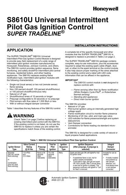
<strong>S8610U</strong> <strong>Universal</strong> <strong>Intermittent</strong><br />
<strong>Pilot</strong> <strong>Gas</strong> <strong>Ignition</strong> Control<br />
SUPER TRADELINE ®<br />
APPLICATION<br />
The SUPER TRADELINE ® <strong>S8610U</strong> <strong>Universal</strong><br />
<strong>Intermittent</strong> <strong>Pilot</strong> <strong>Gas</strong> <strong>Ignition</strong> Control Module is designed<br />
to provide easy field replacement of a wide range of<br />
intermittent pilot ignition modules manufactured by<br />
Honeywell, Robertshaw, Johnson Controls, and others.<br />
The <strong>S8610U</strong> control provides ignition sequence, flame<br />
monitoring, and safety shutoff for intermittent pilot central<br />
furnaces, residential boilers, and other heating<br />
appliances. The <strong>S8610U</strong> replaces existing flame<br />
rectification type, intermittent pilot ignition modules with<br />
the following characteristics:<br />
• Single rod (local sense) or two rod (remote sense)<br />
flame sensing<br />
• Non-100 percent shutoff, 100 percent shutoff/lockout,<br />
or 100 percent shutoff/continuous retry<br />
• Natural or LP gas<br />
• Shutoff/lockout times of 15 seconds or longer<br />
• Prepurge configurable to 30 seconds or no prepurge<br />
• <strong>Pilot</strong> burners with flow rates of 1,500 Btuh or less<br />
• With or without integral damper connector<br />
Table 1 describes the key features of the <strong>S8610U</strong> control.<br />
WARNING<br />
Check Table 2 on page 2 before replacing an<br />
existing intermittent pilot control with the <strong>S8610U</strong>.<br />
If the existing control is not listed, do not use the<br />
<strong>S8610U</strong> to replace it unless you are certain the<br />
specifications match those of the existing control.<br />
INSTALLATION INSTRUCTIONS<br />
A complete list of the specific Honeywell and other<br />
modules that the SUPER TRADELINE ® <strong>S8610U</strong> is<br />
designed to replace is provided in Table 2 on page 2.<br />
The SUPER TRADELINE ® <strong>S8610U</strong> package contains<br />
complete, easy-to-use instructions, plus the accessories<br />
required to adapt the existing spark cable (Rajah, stud,<br />
nail, or other) to the spark terminal on the control module.<br />
It also help assure proper marking of the wires attached<br />
to the existing control and a label with LED code<br />
information that can be affixed in the appliance.<br />
IMPORTANT<br />
The <strong>S8610U</strong> control module is not designed to<br />
replace controls with:<br />
— Flame sensing other than by flame rectification<br />
(White Rodgers Cycle-<strong>Pilot</strong> ® , or Robertshaw<br />
thermal sensing)<br />
— Standing pilot appliances<br />
— Direct main burner ignition<br />
The <strong>S8610U</strong> provides:<br />
• Natural or LP gas<br />
• <strong>Pilot</strong> burner ignition using an internally generated high<br />
voltage spark<br />
• Flame rectification circuit to monitor flame presence<br />
• Monitoring of 24 Vac, pilot, and main gas valve<br />
• LED indicator for flame presence/strength and system<br />
status/errors<br />
• Vent Damper connection<br />
• Connections for flame reading via standard microammeter.<br />
The <strong>S8610U</strong> is designed for a wide variety of natural or<br />
liquid propane fueled applications.<br />
Table 1. <strong>S8610U</strong> <strong>Universal</strong> <strong>Intermittent</strong> <strong>Pilot</strong> <strong>Gas</strong> <strong>Ignition</strong> Control.<br />
Igniter-Sensor<br />
Type<br />
Separate<br />
(two rod; remote<br />
flame sensing)<br />
or<br />
Combination<br />
(one rod; local<br />
flame sensing)<br />
Valve Current<br />
Rating<br />
@ 24 Vac<br />
Prepurge<br />
Timing<br />
Trial for<br />
<strong>Pilot</strong><br />
<strong>Ignition</strong><br />
<strong>Ignition</strong><br />
Sequence<br />
Type<br />
<strong>Ignition</strong> Sequence<br />
(After prepurge, if prepurge is<br />
selected)<br />
Integral<br />
Damper<br />
Connector<br />
1.0 A <strong>Pilot</strong><br />
and<br />
2.0 A Main<br />
None or 30<br />
seconds<br />
(field<br />
selectable)<br />
15 or 90<br />
seconds<br />
(field<br />
selectable)<br />
Retry<br />
Spark and pilot gas ON until lightoff or trial<br />
for ignition ends.<br />
• If established flame is lost, trial for<br />
ignition restarts immediately.<br />
• If pilot fails to light, pilot gas and spark<br />
Off (100% shutoff). After 5 minute delay,<br />
a new trial for ignition is initiated. This<br />
sequence continues until lightoff or “Call<br />
for Heat” is removed.<br />
Included for use as<br />
needed.<br />
• If initially installed<br />
and powered up<br />
with damper<br />
attached, unit<br />
must always have<br />
a vent damper<br />
connected.<br />
®<br />
Automatic <strong>Ignition</strong> Systems<br />
ANSI Z21.20<br />
69-1955-01
<strong>S8610U</strong> UNIVERSAL INTERMITTENT PILOT GAS IGNITION CONTROL<br />
For module replacement, the following table indicates the proper Dip Switch settings for Prepurge timing (SW1) and<br />
Trial For <strong>Ignition</strong> timing (SW2). See “Settings and Adjustments” on page 15 for Dip Switch information.<br />
Table 2. <strong>S8610U</strong> Replaces These<br />
Modules<br />
Vendor / Model SW1 SW2<br />
Honeywell<br />
S86A1001<br />
S86A1019<br />
S86A1027<br />
S86A1035<br />
S86B1009<br />
S86B1017<br />
S86B1025<br />
S86C1007<br />
S86C1015<br />
OFF<br />
OFF<br />
S86C1023 OFF ON<br />
S86C1031<br />
S86C1049<br />
S86C1056<br />
S86D1005<br />
OFF OFF<br />
S86D1013 OFF ON<br />
S86D1021<br />
S86E1002<br />
S86E1010<br />
S86E1028<br />
S86E1036<br />
S86E1044<br />
S86E1051<br />
S86E1069<br />
S86E1077<br />
S86E1101<br />
S86E1119<br />
S86E1127<br />
S86F1000<br />
S86F1018<br />
S86F1026<br />
S86F1042<br />
S86F1059<br />
S86F1067<br />
S86F1075<br />
S86F1083<br />
S86F1091<br />
S86G1008<br />
S86G1016<br />
OFF OFF<br />
S86G1024 OFF ON<br />
S86G1032<br />
S86G1057<br />
S86G1073<br />
S86H1006<br />
OFF OFF<br />
S86H1014 OFF ON<br />
S86H1022<br />
S86H1048<br />
S86H1055<br />
OFF OFF<br />
S86H1063 OFF ON<br />
S86H1089<br />
S86H1097<br />
S86H1105<br />
OFF OFF<br />
S86H1113 OFF ON<br />
S86H1121 OFF OFF<br />
S86H1139 OFF ON<br />
S86H1147<br />
S90A1005<br />
S90B1003<br />
S90B1011<br />
OFF OFF<br />
S860C1000<br />
ON OFF<br />
S860D1009<br />
S860D1017 ON ON<br />
S8600A1001<br />
OFF OFF<br />
S8600B1009<br />
S8600B1025<br />
OFF ON<br />
S8600B3005<br />
S8600B3013<br />
S8600C1015<br />
S8600C3003<br />
S8600F1000<br />
S8600F1034<br />
S8600F1042<br />
S8600H1006<br />
OFF OFF<br />
S8600H1014 OFF ON<br />
Table 2. <strong>S8610U</strong> Replaces These<br />
Modules (Continued)<br />
Vendor / Model SW1 SW2<br />
S8600H1022<br />
S8600H1048<br />
S8600H1055<br />
OFF<br />
OFF<br />
S8600H1063 OFF ON<br />
S8600H1071<br />
S8600H1089<br />
S8600H1097<br />
S8600H1105<br />
S8600H3002<br />
OFF OFF<br />
S8600H3010 OFF ON<br />
S8600M1005<br />
S8600M1013<br />
S8600M1021<br />
S8600M2003<br />
S8600M3001<br />
S8600M4009<br />
S8610A1009<br />
S8610B1007<br />
S8610B1015<br />
OFF OFF<br />
S8610B1023<br />
S8610B3003<br />
S8610C1005<br />
S8610C1013<br />
S8610C3001<br />
S8610F1008<br />
S8610F1016<br />
S8610F1024<br />
S8610F1032<br />
OFF<br />
OFF<br />
ON<br />
OFF<br />
S8610H1004 OFF ON<br />
S8610H1012 OFF OFF<br />
S8610H1020 OFF ON<br />
S8610H1038<br />
S8610H1046<br />
S8610H1053<br />
OFF OFF<br />
S8610H1061 OFF ON<br />
S8610H1079<br />
S8610H1095<br />
S8610H3000<br />
OFF OFF<br />
S8610H3018 OFF ON<br />
S8610H3026<br />
OFF OFF<br />
S8610M1003<br />
S8610M1011 OFF ON<br />
S8610M1029<br />
OFF OFF<br />
S8610M3009<br />
S8610M3017 OFF ON<br />
<strong>S8610U</strong>1003<br />
OFF OFF<br />
<strong>S8610U</strong>1011<br />
S8620C1003<br />
OFF ON<br />
S8620C1011<br />
S8620H1002 OFF OFF<br />
S8620H1010 OFF ON<br />
S8620H1028 OFF OFF<br />
S8660D1002 ON OFF<br />
S8660D1010 ON ON<br />
S8660J1008<br />
S8660J1016<br />
S8660J1024<br />
S8660K1006<br />
S8660K1014<br />
S8660K1022<br />
S8670D1000<br />
S8670D1018<br />
ON OFF<br />
S8670D1026<br />
S8670D3006<br />
S8670D3014<br />
S8670E1007<br />
S8670E3003<br />
ON<br />
ON<br />
ON<br />
OFF<br />
S8670J3002 ON ON<br />
Table 2. <strong>S8610U</strong> Replaces These<br />
Modules (Continued)<br />
Vendor / Model SW1 SW2<br />
S8670J3010<br />
ON OFF<br />
S8670K3000<br />
S8680J1004 ON ON<br />
Johnson Controls<br />
CSA35A-617R<br />
CSA35A-618R<br />
CSA42A-600R<br />
CSA42A-601R<br />
CSA42A-602R<br />
CSA42A-603R<br />
CSA42A-604R<br />
CSA43A-600R<br />
CSA44A-600R<br />
CSA45A-601R<br />
CSA45A-602R<br />
CSA46A-600R<br />
CSA48A-600R<br />
CSA49A-600R<br />
CSA49A-605R<br />
CSA51A-601R<br />
CSA52A-600R<br />
OFF OFF<br />
G60AAA-1<br />
G60AAG-1<br />
G60AAG-2<br />
G60AAG-3<br />
G60AAG-4<br />
G60AAG-5<br />
G60AAG-6<br />
G60AAG-7<br />
G60CAA-1<br />
G60CAA-3<br />
G60CAG-1<br />
G60CAG-2<br />
G60CAG-3<br />
G60CAG-4<br />
G60CAG-5<br />
G60CAG-6<br />
G60CAG-7<br />
G60CAG-8<br />
G60CAG-9<br />
G60CBA-1<br />
G60CBA-2<br />
G60CBA-3<br />
G60CBG-1<br />
G60CBG-2<br />
G60CBG-3<br />
G60CBG-4<br />
G60CBG-5<br />
G60CBG-6<br />
G60CBG-7<br />
G60CBG-8<br />
G60CBG-9<br />
G60CBG-10<br />
G60CBG-11<br />
G60CBG-12<br />
G60CBG-13<br />
G60CBG-14<br />
G60CBG-15<br />
G60CBG-16<br />
G60CBG-17<br />
G60CCA-1<br />
G60CCG-1<br />
G60CPG-1<br />
G60DBG-1<br />
G60DCG-1<br />
G60DCG-2<br />
G60DCG-3<br />
G60DCG-4<br />
G60PAG-1<br />
G60PAG-2<br />
G60PAG-3<br />
G60PAG-4<br />
G60PAG-5<br />
G60PAG-6<br />
G60PAJ-1<br />
G60PAK-1<br />
G60PAK-2<br />
G60PFH-1<br />
G60PFH-2<br />
G60PFL-1<br />
G60PFQ-1<br />
G60PVL-1<br />
G60QAG-1<br />
G60QAG-2<br />
G60QAG-3<br />
OFF<br />
OFF<br />
69-1955—01 2
<strong>S8610U</strong> UNIVERSAL INTERMITTENT PILOT GAS IGNITION CONTROL<br />
Table 2. <strong>S8610U</strong> Replaces These<br />
Modules (Continued)<br />
Vendor / Model SW1 SW2<br />
G60QAG-4<br />
G60QAK-1<br />
G60QBG-1<br />
G60QBG-2<br />
G60QBG-3<br />
G60QBG-4<br />
G60QBG-5<br />
G60QBG-6<br />
G60QBG-7<br />
G60QBG-8<br />
G60QBG-9<br />
G60QBH-1<br />
G60QBK-1<br />
G60QBK-2<br />
G60QBK-3<br />
G60QBL-1<br />
G60QBL-2<br />
G60QCG-1<br />
G60QCJ-1<br />
G60QCL-1<br />
G60QDG-1<br />
G60QFL-1<br />
G60QGH-1<br />
G60QHL-1<br />
G60QHL-2<br />
G60QJL-1<br />
G60QLG-1<br />
G60QLK-1<br />
G60QPL-1<br />
G60QRH-1<br />
G60QRH-2<br />
G60QRH-3<br />
G60QRL-1<br />
G60QRL-2<br />
G60QRL-3<br />
G60QSL-1<br />
G60QTH-1<br />
G60QTL-1<br />
G60RAG-1<br />
G60RAK-1<br />
G60RBG-1<br />
G60RBG-2<br />
G60RBG-3<br />
G60RBK-1<br />
G60RBK-2<br />
G60RCG-1<br />
G60RCG-2<br />
G60RCJ-1<br />
G60RDG-1<br />
G60RDK-1<br />
G60RGL-1<br />
G60RHL-1<br />
G60RHP-1<br />
G60RPL-1<br />
G60RSL-1<br />
G60TTL-1<br />
G60ZAG-1<br />
G60ZAG-2<br />
G65BBG-1<br />
G65BBG-2<br />
G65BBG-3<br />
G65BBG-4<br />
G65BBG-5<br />
G65BBG-6<br />
G65BBG-7<br />
G65BBG-8<br />
G65BBM-1<br />
G65BBM-2<br />
G65BBM-3<br />
G65BBM-4<br />
G65BCG-1<br />
G65BCM-1<br />
G65BFG-1<br />
G65BFM<br />
G65BKG-1<br />
G65BKG-2<br />
G65BKG-3<br />
G65BKM-1<br />
G65BKM-2<br />
G65BKM-3<br />
G65BLG-1<br />
G65BLG-2<br />
G65DBG<br />
G65DBM-1<br />
G65DBM-2<br />
G65DBM-3<br />
G65DCM-1<br />
G65DFG<br />
G65DFM-1<br />
G65DKG<br />
G65DKM<br />
G65DKM-1<br />
G65DLM-1<br />
G65FBG<br />
G65FFG<br />
G65FKG<br />
OFF<br />
OFF<br />
OFF<br />
OFF<br />
Table 2. <strong>S8610U</strong> Replaces These<br />
Modules (Continued)<br />
Vendor / Model SW1 SW2<br />
G66AG-1<br />
G66AG-2<br />
G66BG-1<br />
G66MG-1<br />
G66MG-2<br />
G66NG-1<br />
G67AG-3<br />
G67AG-4<br />
G67AG-7<br />
G67AG-8<br />
G67AG-9<br />
G67AG-10<br />
G67AG-11<br />
G67BG-2<br />
G67BG-3<br />
G67BG-4<br />
G67BG-5<br />
G67MG-1<br />
G67MG-2<br />
G67MG-3<br />
G67MG-4<br />
G67NG-2<br />
G67NG-4<br />
G600AX-1<br />
G600AX-2<br />
G600AX-3<br />
G600AY-1<br />
G600LX-1<br />
G600LX-2<br />
G600LY-1<br />
G600MX-1<br />
G600NX-1<br />
G600RX-1<br />
G670AW-1<br />
G670AW-2<br />
G670GA-1<br />
G770LGA-1<br />
G770LGA-2<br />
G770LGC-1<br />
G770LGC-2<br />
G770LGC-3<br />
G770LGC-4<br />
G770LHA-1<br />
G770LHA-2<br />
G770LHC-1<br />
G770MGA-1<br />
G770MGA-2<br />
G770MGA-3<br />
G770MGC-1<br />
G770MGC-2<br />
G770MGC-3<br />
G770MGC-4<br />
G770MGC-5<br />
G770MGC-6<br />
G770MHA-1<br />
G770MHA-2<br />
G770MHC-1<br />
G770NGA-1<br />
G770NGC-4<br />
G770NGC-5<br />
G770NGC-6<br />
G770NGC-7<br />
G770NHA-1<br />
G770NHC-1<br />
G770RGA-1<br />
G770RHA-1<br />
G770RHA-2<br />
G775RGA-1<br />
G775RHA-1<br />
G775RHA-2<br />
OFF<br />
OFF<br />
OFF<br />
OFF<br />
OFF<br />
OFF<br />
OFF<br />
OFF<br />
OFF<br />
OFF<br />
OFF<br />
OFF<br />
G779 OFF OFF<br />
Y79ABC-1<br />
Y79ABC-2<br />
Y79ABC-3<br />
Y79ABC-4<br />
Y79ABC-5<br />
Y79ABC-6<br />
Y79ABC-7<br />
Y79ABD-1<br />
Y79ABCD-2<br />
Y79BBA-1<br />
Y79BBA-2<br />
OFF OFF<br />
Table 2. <strong>S8610U</strong> Replaces These<br />
Modules (Continued)<br />
Vendor / Model SW1 SW2<br />
RobertShaw<br />
780-001<br />
OFF OFF<br />
780-002<br />
780-003 ON OFF<br />
780-845<br />
780-715<br />
780-735<br />
780-736<br />
780-737<br />
OFF OFF<br />
SP715<br />
SP715A<br />
SP735<br />
SP735D<br />
SP735L<br />
OFF<br />
SPECIFICATIONS<br />
Control Voltage:<br />
Line 24 V (18-30 Vac) 50/60 Hz<br />
Anticipator Setting:<br />
0.1 A plus valve load @ 24 Vac<br />
Trial for <strong>Ignition</strong>:<br />
See Table 1 on page 1<br />
Prepurge: See Table 1 on page 1<br />
Flame Failure Response Time:<br />
2 seconds maximum<br />
LED:<br />
The green Status LED provides<br />
system status, error codes, and<br />
flame strength when in run<br />
mode.<br />
Typical <strong>Gas</strong> Control: Honeywell<br />
models VR8204 and VR8304<br />
Operating Temperature:<br />
Minimum ambient temperature<br />
rating is -40°F (-40°C)<br />
Maximum ambient rating when<br />
used with 2.0 A main valve is<br />
165°F (74°C)<br />
Relative Humidity:<br />
0% to 95% non condensing<br />
OFF<br />
USI715U OFF OFF<br />
White-Rodgers<br />
50D49-350<br />
OFF OFF<br />
50D49-360<br />
50D49-361 ON OFF<br />
50D49-401 OFF OFF<br />
Camstat<br />
IPI-24-00 OFF OFF<br />
Fenwal<br />
05-203025-005<br />
05-203026-005<br />
OFF OFF<br />
1003-3<br />
1003-300<br />
HSC<br />
OFF<br />
OFF<br />
3 69-1955—01
<strong>S8610U</strong> UNIVERSAL INTERMITTENT PILOT GAS IGNITION CONTROL<br />
PLANNING THE<br />
INSTALLATION<br />
WARNING<br />
Fire or Explosion Hazard.<br />
Can cause severe injury, death or property<br />
damage.<br />
1. Plan the installation as outlined below.<br />
2. Plan for frequent maintenance as described in<br />
the Maintenance section.<br />
<strong>Intermittent</strong> pilot systems are used on a wide variety of<br />
central heating equipment and on heating appliances<br />
such as commercial cookers, agricultural equipment,<br />
industrial heating equipment and pool heaters. Some of<br />
these applications may make heavy demands on the<br />
controls, either because of frequent cycling, or because of<br />
moisture, corrosive chemicals, dust or excessive heat in<br />
the environment. In these situations, special steps may be<br />
required to prevent nuisance shutdowns and premature<br />
control module failure. These applications require special<br />
Honeywell review; contact your Honeywell Sales<br />
Representative for assistance.<br />
Review the following conditions that can apply to your<br />
specific installation and take the precautionary steps<br />
suggested.<br />
Frequent Cycling<br />
These controls are designed for use on appliances that<br />
typically cycle three to four times an hour only during the<br />
heating season. In year-round applications with greater<br />
cycling rates, the control module can wear out more<br />
quickly; perform a monthly checkout.<br />
Water or Steam Cleaning<br />
If the control module gets wet, replace it. If the appliance<br />
is likely to be cleaned with water or steam, protect (cover)<br />
the controls and wiring from water or steam flow. Mount<br />
the controls high enough above the bottom of the cabinet<br />
so they do not get wet during normal cleaning procedures.<br />
Use a NEMA 4 enclosure for the ignition control module.<br />
High Humidity or Dripping Water<br />
Dripping water can cause the control module to fail. Never<br />
install an appliance where water can drip on the controls.<br />
In addition, high ambient humidity can cause the gas<br />
control to corrode and fail.<br />
If the appliance is in a humid atmosphere, make sure air<br />
circulation around the controls is adequate to prevent<br />
condensation. Also, regularly check out the system. A<br />
NEMA 4 enclosure is recommended for the ignition<br />
control module.<br />
Corrosive Chemicals<br />
Corrosive chemicals can attack the ignition control<br />
module and gas control, eventually causing a failure. If<br />
chemicals are used for routine cleaning, make sure they<br />
do not reach the controls. Where chemicals are<br />
suspended in air, as in some industrial or agricultural<br />
applications, use a NEMA 4 enclosure for the ignition<br />
control module.<br />
Dust or Grease Accumulation<br />
Heavy accumulations of dust or grease can cause<br />
controls to malfunction. Where dust or grease can be a<br />
problem, provide covers for the ignition control module<br />
and the gas control to limit contamination. A NEMA 4<br />
enclosure is recommended for the ignition control module.<br />
Heat<br />
Excessively high temperatures can damage controls.<br />
Make sure the maximum ambient temperature at the<br />
control module does not exceed the rating of the control<br />
module. If the appliance operates at very high<br />
temperatures, use insulation, shielding, and air<br />
circulation, as necessary, to protect the controls. Proper<br />
insulation or shielding should be provided by the<br />
appliance manufacturer; verify proper air circulation is<br />
maintained when the appliance is installed.<br />
INSTALLATION<br />
When Installing This Product…<br />
1. Read these instructions carefully. Failure to follow<br />
them could damage the product or cause a hazardous<br />
condition.<br />
2. Check the ratings given in these instructions to<br />
make sure the <strong>S8610U</strong> module is suitable for your<br />
application.<br />
3. Installer must be a trained, experienced service<br />
technician.<br />
4. After installation is complete, check out operation<br />
as provided in these instructions.<br />
WARNING<br />
Fire or Explosion Hazard.<br />
Can cause severe injury, death or property<br />
damage.<br />
1. The ignition control module can malfunction if it<br />
gets wet, leading to accumulation of explosive<br />
gas.<br />
—Never install where water can flood, drip or<br />
condense on the ignition control module.<br />
—Never try to use an ignition control module<br />
that has been wet; replace it.<br />
2. Liquefied petroleum (LP) gas is heavier than air<br />
and will not naturally vent upward.<br />
—Do not operate electric switches, lights, or<br />
appliances until you are sure the appliance<br />
area is free of gas.<br />
WARNING<br />
Electrical Shock Hazard.<br />
Can cause severe injury, death or property<br />
damage.<br />
Disconnect power supply before beginning wiring<br />
or making wiring connections to prevent electrical<br />
shock or equipment damage.<br />
69-1955—01 4
<strong>S8610U</strong> UNIVERSAL INTERMITTENT PILOT GAS IGNITION CONTROL<br />
CAUTION<br />
1. If a new gas control is to be installed, turn off<br />
the gas supply before starting installation.<br />
Conduct a <strong>Gas</strong> Leak Test according to the gas<br />
control manufacturer instructions after the gas<br />
control is installed.<br />
2. Wiring errors can cause improper appliance<br />
operation and dangerous conditions such as<br />
bypassing safety features.<br />
CAUTION<br />
Equipment Damage Hazard.<br />
Water can cause equipment damage or<br />
malfunction.<br />
If ignition control module must be mounted where<br />
there is the potential for exposure to water or<br />
moisture, provide a suitable waterproof enclosure.<br />
Maintenance Requirements in<br />
Severe Environments<br />
Regular preventive maintenance is important in any<br />
application, but especially so in commercial cooking,<br />
agricultural, and industrial applications because:<br />
• In many such applications, particularly commercial<br />
cooking, the equipment operates 100,000-200,000 cycles<br />
per year. Such heavy cycling can wear out the gas control<br />
in one to two years. A normal forced air furnace, for which<br />
the controls were originally intended, typically operates<br />
less than 20,000 cycles per year.<br />
• Exposure to water, dirt, chemicals, and heat can<br />
damage the ignition control module or the gas control and<br />
shut down the control system. A NEMA 4 enclosure can<br />
reduce exposure to environmental contaminants.<br />
The maintenance program should include regular<br />
checkout of the system as outlined under “Checkout” on<br />
page 15.<br />
WARNING<br />
Fire or Explosion Hazard.<br />
Can cause severe injury, death or property<br />
damage.<br />
Do not attempt to take the ignition control module<br />
apart or to clean it. Improper reassembly and<br />
cleaning may cause unreliable operation.<br />
Maintenance frequency must be determined individually<br />
for each application. Some considerations are:<br />
• Cycling frequency – Appliances that may cycle more<br />
than 20,000 times annually should be checked<br />
monthly.<br />
• <strong>Intermittent</strong> use – Appliances that are used seasonally<br />
should be checked before shutdown and again before<br />
the next use.<br />
• Consequence of unexpected shutdown – Where the<br />
cost of an unexpected shutdown would be high, the<br />
system should be checked more often.<br />
• Dusty, wet, or corrosive environment – Since these<br />
environments can cause the controls to deteriorate<br />
more rapidly, the system should be checked more<br />
often.<br />
Any ignition control module should be replaced if it does<br />
not perform properly on checkout or troubleshooting. In<br />
addition, replace any ignition control module if it is wet or<br />
looks like it has ever been wet. Protective enclosures as<br />
outlined under “Planning the Installation” are<br />
recommended regardless of checkout frequency.<br />
Perform Pre-Installation Safety<br />
Check<br />
The pre-installation checks described below must be<br />
done before the replacement ignition control module is<br />
installed. If a condition that could result in unsafe<br />
operation is detected, the appliance should be shut off<br />
and the owner advised of the unsafe condition. Correct<br />
any potentially unsafe condition before proceeding with<br />
the installation.<br />
The following safety checklist should be followed in<br />
making the safety inspection:<br />
1. Conduct a <strong>Gas</strong> Leakage Test of the appliance piping<br />
and control system downstream of the shutoff<br />
valve in the supply line to the appliance.<br />
2. Visually inspect the venting system for proper size<br />
and horizontal pitch and determine there is no<br />
blockage or restrictions, leakage or corrosion or<br />
other deficiencies that could cause an unsafe condition.<br />
3. Shut off all gas to the appliance and shut off any<br />
other fuel-burning appliance within the same room.<br />
Use the shutoff valve in the supply line to each<br />
appliance.<br />
4. Inspect burners and crossovers for blockage and<br />
corrosion.<br />
5. Applicable only to warm air heating appliances.<br />
Inspect heat exchangers for cracks, openings or<br />
excessive corrosion.<br />
6. Applicable only to boilers. Inspect for evidence of<br />
water or combustion product leaks.<br />
7. Insofar as is practical, close all building doors and<br />
windows and all doors between the space in which<br />
the appliance is located and other spaces of the<br />
building. Turn on clothes dryers. Turn on any<br />
exhaust fans, such as range hoods and bathroom<br />
exhausts, so they will operate at maximum speed.<br />
Do not operate a summer exhaust fan.<br />
Close fireplace dampers.<br />
If, after completing steps 7 through 12 in this safety<br />
checklist, it is believed sufficient combustion air is<br />
not available, refer to section 1.3.4 of the National<br />
Fuel <strong>Gas</strong> Code (Z223.1) for guidance.<br />
8. Place in operation the appliance being inspected.<br />
Follow the lighting instructions. Adjust thermostat so<br />
appliance will operate continuously.<br />
a. Determine that the pilot is burning properly and<br />
that main burner ignition is satisfactory by interrupting<br />
and reestablishing the electrical supply<br />
to the appliance in any convenient manner.<br />
b. Determine manifold pressure in order to match<br />
input after the new control is installed.<br />
c. Visually determine that main burner gas is burning<br />
properly; i.e., no floating, lifting or flashback.<br />
Adjust the primary air shutter(s) as required.<br />
d. If appliance is equipped with high and low flame<br />
control or flame modulation, check for proper<br />
main burner operation at low flame.<br />
9. Test for spillage at the draft hood relief opening after<br />
five minutes of main burner operation. Use a draft<br />
gauge, the flame of a match or candle, or smoke<br />
from a cigarette, cigar or pipe.<br />
5 69-1955—01
<strong>S8610U</strong> UNIVERSAL INTERMITTENT PILOT GAS IGNITION CONTROL<br />
10. Return doors, windows, exhaust fans, fireplace<br />
dampers and all other fuel-burning appliances to<br />
their previous conditions of use.<br />
11. Applicable only to warm air heating appliances.<br />
Check both limit controller and fan controller for<br />
proper operation. Limit controller operation can be<br />
checked by temporarily disconnecting the electrical<br />
supply to the blower motor and determining that the<br />
limit control acts to shut off the main burner gas.<br />
12. Applicable only to boilers:<br />
a. Determine that the circulating water pumps are<br />
in operating condition.<br />
b. Test low water cutoffs, automatic feed controls,<br />
pressure and temperature limit controls and<br />
relief valves in accordance with the manufacturer’s<br />
recommendations and instructions to<br />
determine they are in operating condition.<br />
Remove Old <strong>Ignition</strong> Control<br />
Module<br />
Disconnect power supply before doing any work on the<br />
unit. Disconnect and tag the wires from the old module.<br />
Remove the old module from its mounting location.<br />
Mount New <strong>Ignition</strong> Control<br />
Module<br />
The recommended mounting for the <strong>S8610U</strong> ignition<br />
control module is the same location as the old control<br />
module. Otherwise, select a location close enough to the<br />
burner to allow a short (3 ft. [0.9 m] maximum), direct<br />
cable route to the pilot burner. Ambient temperature at the<br />
control module must be within the range listed in the<br />
“Specifications” on page 3.<br />
Mount the ignition control module with the terminals down<br />
to protect them from dripping water and dust. The control<br />
module can also be mounted with the terminals on either<br />
side. Do not mount with the terminals pointing up. Fig. 1<br />
on page 6 illustrates the incorrect mounting position.<br />
When it is necessary to drill new mounting holes, use the<br />
<strong>S8610U</strong> as a template to mark the mounting hole pattern.<br />
Drill new holes, as required. Fasten securely with four —<br />
No. 6-32 machine screws, or No. 8 sheet metal screws, or<br />
8-18 x 5/8 Pan Head tapping screws.<br />
Location<br />
The mounting location must provide:<br />
— Good, clear access to the field wiring terminals.<br />
— Operating ambient temperatures between<br />
-40°F (-40°C) and 165°F (74°C).<br />
— Relative humidity below 95% non condensing.<br />
— Protection from water, steam or corrosive chemicals<br />
that are used to clean the appliance.<br />
— Protection from dripping water, such as from an<br />
overfilled humidifier or from condensation.<br />
— Protection from dust or grease accumulation.<br />
IMPORTANT<br />
Do not mount with terminals facing up.<br />
Wire the System<br />
Fig. 1. Incorrect Mounting.<br />
M29889<br />
CAUTION<br />
Equipment Damage Hazard.<br />
Disconnect power supply before beginning wiring<br />
or making wiring connections to prevent electrical<br />
shock or equipment damage.<br />
All wiring must comply with local codes and ordinances.<br />
Refer to Fig. 2 and Table 9 on page 11 for typical<br />
connections.<br />
IMPORTANT<br />
1. As shown in the wiring diagrams, a common<br />
ground is required on:<br />
The pilot burner mounting bracket, and the GND<br />
(BURNER) terminal on the ignition control module.<br />
Failure to use the GND (BURNER) terminal<br />
may result in intermittent loss of spark and/or<br />
loss of flame current sensitivity.<br />
2. Make sure the transformer has adequate VA.<br />
The ignition control module requires at least<br />
0.1 A at 24 Vac. Add the current draws of all<br />
other devices in the control circuit, including the<br />
pilot and main valves in the gas control, and multiply<br />
by 24 to determine the total VA requirement<br />
of these components. Add this total to 2.4 VA (for<br />
the ignition control module). The result is the<br />
minimum transformer VA rating. Use a Class II<br />
transformer if replacement is required.<br />
Connect Vent Damper (Optional)<br />
If the ignition control module is to be used with a damper<br />
connected to the module’s integral damper connector in<br />
an atmospheric appliance, perform the following to<br />
connect it to the module:<br />
IMPORTANT<br />
After the initial power-up, the ignition control<br />
module senses the presence of the vent damper<br />
connection. If the vent damper is connected for<br />
10 ignition cycles, the ignition control module<br />
permanently configures itself to operate only<br />
with the damper connected.<br />
Once an ignition control module completes 10<br />
ignition cycles with a vent damper connected,<br />
the module will not function without a vent<br />
damper being connected.<br />
69-1955—01 6
<strong>S8610U</strong> UNIVERSAL INTERMITTENT PILOT GAS IGNITION CONTROL<br />
1. Using the wiring harness on the appliance, insert<br />
the matching 6-pin plug into the connector (labeled<br />
P1; see Fig. 2 on page 11) on the <strong>S8610U</strong> ignition<br />
control module and connect the other end to the<br />
vent damper.<br />
NOTE: The connector (P1) accepts a Molex 03-06-2061<br />
plug.<br />
Connect <strong>Ignition</strong> Cable<br />
Use existing ignition cable if it is in good condition. If the<br />
existing ignition cable does not have a 1/4 in. quick<br />
connect on the module end, either use the Rajah adapter<br />
or strip the wire and replace with the 1/4 in. insulated<br />
quick connect supplied. If the cable must be replaced,<br />
order a Honeywell ignition cable (Table 3) or refer to Table<br />
4. It might be necessary to replace the connector at the<br />
pilot burner end to match the pilot burner spark<br />
termination.<br />
NOTE:<br />
When using an <strong>S8610U</strong> to replace an S86, use<br />
the enclosed adapter to convert the S86 <strong>Ignition</strong><br />
Cable to an <strong>S8610U</strong> <strong>Ignition</strong> Cable. Then, install<br />
the adapter and cable to the <strong>S8610U</strong> <strong>Ignition</strong><br />
Module.<br />
Table 3. Honeywell Pre-assembled <strong>Ignition</strong> Cables<br />
(UL Style 3257).<br />
CABLE<br />
PART<br />
NUMBER<br />
LENGTH<br />
MODULE<br />
END<br />
394800-30 30 inches 1/4 inch quick<br />
connect,<br />
insulated<br />
394801-30 30 inches 1/4 inch quick<br />
connect,<br />
insulated<br />
PILOT BURNER<br />
Rajah connector<br />
receptacle, 90<br />
degree rubber boot<br />
Rajah connector<br />
receptacle, straight<br />
rubber boot<br />
Connect <strong>Ignition</strong> Control Module<br />
CAUTION<br />
Equipment Damage Hazard.<br />
Check the wiring diagram provided on the<br />
appliance and compare with Table 5 through Table<br />
8 beginning on page 8. Carefully follow any<br />
special instructions affecting the general wiring<br />
procedures outlined in this section.<br />
1. Connect the wires to the module as shown in the<br />
wiring tables (Table 5 through Table 8). Make sure<br />
that adequate system ground is provided as indicated<br />
in the wiring tables.<br />
(Refer to Fig. 2 and Table 9 on page 11 for wiring<br />
connections on the <strong>S8610U</strong> module.)<br />
2. Verify the thermostat anticipator setting as<br />
explained in the Important notes in the wiring tables.<br />
NOTE: Refer to Fig. 2 and Table 9 on page 11 for the<br />
location of each connection on the <strong>S8610U</strong> module.<br />
The wiring diagrams in Fig. 3 through Fig. 5 beginning on<br />
page 12 describe typical hookups with the <strong>S8610U</strong><br />
module and should be used for reference only.<br />
• Fig. 3 shows a basic circuit used only for heating<br />
systems with atmospheric burners and damper control.<br />
(Shown with local and remote flame sensing.)<br />
• Fig. 4 shows a basic circuit used only for heating<br />
systems with atmospheric burners without damper<br />
control. (Shown with local and remote flame sensing.)<br />
• Fig. 5 shows a circuit for power assisted combustion<br />
applications.<br />
Table 4. Recommended <strong>Ignition</strong> Cable for Field<br />
Assembly.<br />
CABLE TYPE<br />
VOLTAGE RATING<br />
(rms)<br />
TEMPERATURE<br />
RATING<br />
UL Style 3217 10,000 302°F (150°C)<br />
UL Style 3257 10,000 484°F (250°C)<br />
Cable must be no longer than 36 in. (0.9 m). Solid<br />
conductor cable recommended. To construct a cable, fit<br />
one end of ignition cable with 1/4 in. diameter Rajah<br />
connector receptacle and the other with a 1/4 in. female<br />
quick connect. Protect both ends with insulated boots.<br />
NOTE: The cable must not run in continuous contact<br />
with a metal surface or spark voltage may be<br />
greatly reduced. Use ceramic or plastic standoff<br />
insulators as required. Resistive spark cable<br />
reduces spark voltage and may impact appliance<br />
performance.<br />
To install:<br />
1. Connect one end of the cable to the male quick<br />
connect SPARK terminal on the ignition module.<br />
2. Connect the other end of the cable to the igniter or<br />
igniter-sensor stud on the pilot burner/ignitersensor.<br />
7 69-1955—01
<strong>S8610U</strong> UNIVERSAL INTERMITTENT PILOT GAS IGNITION CONTROL<br />
The following four tables describe the wiring connections necessary for conversion:<br />
Table 5. Conversion from Honeywell <strong>Intermittent</strong> <strong>Pilot</strong> Modules.<br />
Replacement<br />
Control<br />
Old Control<br />
Terminal<br />
Function<br />
Main Valve<br />
Operator<br />
Main Valve<br />
and <strong>Pilot</strong><br />
Common<br />
<strong>Pilot</strong> Valve<br />
Operator<br />
Burner<br />
Ground<br />
Connection<br />
Transformer<br />
Secondary<br />
(unswitched<br />
leg)<br />
Transformer<br />
Secondary<br />
(switched<br />
leg)<br />
Flame<br />
Sensor<br />
Igniter /<br />
Sensor<br />
<strong>S8610U</strong> S86A,C S86B,D S86E,F,G,H<br />
S90A,B<br />
S8600A,B,C<br />
S8610A,B,C<br />
<strong>S8610U</strong>1003<br />
S8620C,<br />
S8660D,J<br />
S8670D,J<br />
S8680D,J<br />
S8600F,H,M<br />
S8610F,H,M<br />
S8660E,K<br />
S8670E,K<br />
MV MV MV MV MV MV —<br />
MV/PV MV/PV MV/PV MV/PV MV/PV MV/PV —<br />
PV PV PV PV PV PV —<br />
GND<br />
(BURNER)<br />
GND GND GND<br />
(BURNER)<br />
24V GND 25V (2) 25V 25V (2) a<br />
GND (BURNER) GND (BURNER) —<br />
24V GND 24V GND —<br />
Procedural Notes<br />
24V * 25V (2) 25V 25V (2) a * 24V * 24V * * IMPORTANT<br />
25V (2) or 24V used only in systems where plug-in If the old module had a<br />
cable connects damper to module<br />
vent damper connector but<br />
a vent damper was not<br />
TH-W<br />
TH-R b TH-R b TH-R b TH-W<br />
TH-W<br />
installed, or if it did not<br />
(This terminal is<br />
have a vent damper<br />
connector, then connect<br />
TH-W c TH-W<br />
TH-W c not included on<br />
S90.)<br />
the 25V (2) or 24V wire<br />
from the old module to the<br />
TH-W terminal on the<br />
<strong>S8610U</strong>. Do not use the<br />
24V terminal on the<br />
<strong>S8610U</strong>.<br />
If the old module had a<br />
vent damper, connect it to<br />
the P1 connector on the<br />
module, and wire the<br />
terminals as indicated in<br />
the table.<br />
SENSE d<br />
SPARK<br />
e<br />
IGN COIL f<br />
e e SENSE d e —<br />
IGN COIL f IGN COIL f SPARK SPARK —<br />
a Terminals may be marked 25V on some models and 24V on later models. These are functionally equivalent.<br />
b If 25V (2) and TH-R have wires connected, disconnect and splice together with solderless connector.<br />
c If TH-R and TH-W are jumpered together, connect 25V (2) lead from S86 to TH-W on <strong>S8610U</strong>.<br />
d On dual igniter and sensor models, remove jumper wire quick connect from <strong>S8610U</strong> Remote Sense terminal, then cut<br />
jumper wire at circuit board and discard.<br />
e Leave black jumper connected.<br />
f Use Rajah to quick connector adapter (supplied) or cut Rajah connector off ignition cable at module end and attach<br />
insulated quick connect for connection to <strong>S8610U</strong>.<br />
69-1955—01 8
<strong>S8610U</strong> UNIVERSAL INTERMITTENT PILOT GAS IGNITION CONTROL<br />
Table 6. Conversion from Johnson Controls CSA — (All), G60, G65, G66, G67, G600, G670 and G770.<br />
Replacement<br />
Control<br />
Old<br />
Control<br />
Terminal<br />
Function<br />
Main Valve<br />
Operator<br />
Main Valve<br />
and <strong>Pilot</strong><br />
Common<br />
<strong>Pilot</strong> Valve<br />
Operator<br />
Burner<br />
Ground<br />
Connection<br />
Transformer<br />
Secondary<br />
(unswitched<br />
leg)<br />
Transformer<br />
Secondary<br />
(switched<br />
leg)<br />
Flame<br />
Sensor<br />
Igniter /<br />
Sensor<br />
<strong>S8610U</strong><br />
CSA45A-60R a , G60, G65, G66, G67, G600, or G670<br />
Installation with Lockout Modules as follows:<br />
None (Y79)<br />
Y79A module b<br />
Y79A module c<br />
G770<br />
MV 3 3 Y79B MV MV (3) —<br />
MV/PV GR GR GR GROUND (5) —<br />
PV 1 1 Y79B PV PV (1) —<br />
GND<br />
(BURNER)<br />
GR GR GR GROUND —<br />
24V GND GR GR GR GROUND —<br />
TH-W *<br />
2 d<br />
Y79 THS 2 TH-S (2) —<br />
24V ** No Connection ** No Connection ** No Connection ** No Connection **<br />
SENSE *<br />
4 e<br />
4 e 4 e SENSE (4) e —<br />
Procedural Notes<br />
SPARK IGN COIL IGN COIL IGN COIL IGN COIL It might be necessary to cut off<br />
the Rajah connector and/or<br />
attach an insulated, 1/4 inch<br />
quick connect.<br />
a CSA code numbers (for example, CSA45A-600R) are equivalent to G600 and use the same wiring information tables.<br />
b Discard wires between Y79A and module as follows: Red to 3, Black to 2, White to GR. Discard wire between transformer<br />
and 6.<br />
c Discard wires between Y79B and module as follows: White to 3, Black to 1, Brown to GR. Discard wire between transformer<br />
and 6.<br />
d Discard wire between transformer and terminal 5 (G60) or 6 (G600); otherwise, use existing harness for wiring.<br />
e Important: Remove black jumper quick connect from Remote Sense terminal of <strong>S8610U</strong>. Cut jumper wire at circuit<br />
board and discard.<br />
* IF INSTALLATION DOES NOT INCLUDE VENT<br />
DAMPER WITH PLUG CONNECTION TO MODULE:<br />
1. Connect the “Call for Heat” thermostat wire to the<br />
TH-W terminal.<br />
** IF INSTALLATION INCLUDES VENT DAMPER WITH<br />
PLUG CONNECTION TO MODULE:<br />
1. Connect the vent damper’s Molex connector to the<br />
vent damper connector (P1) on the module.<br />
2. Connect the thermostat W wire to TH-W.<br />
3. Run wire from switched leg of transformer secondary<br />
to both thermostat R and <strong>S8610U</strong> Module 24V<br />
terminals.<br />
9 69-1955—01
<strong>S8610U</strong> UNIVERSAL INTERMITTENT PILOT GAS IGNITION CONTROL<br />
Table 7. Conversion from Robertshaw SP715 and SP735C (includes 780-XXX and USI715U).<br />
Terminal<br />
Function<br />
Replacement<br />
Control<br />
<strong>S8610U</strong><br />
7000D Valve b<br />
Old Control a<br />
7100D Valve<br />
7100K Valve<br />
Procedural Notes<br />
Main Valve<br />
Operator<br />
Main Valve and<br />
<strong>Pilot</strong> Common<br />
<strong>Pilot</strong> Valve<br />
Operator<br />
Burner Ground<br />
Connection<br />
Transformer<br />
Secondary<br />
(unswitched leg)<br />
Transformer<br />
Secondary<br />
(switched leg)<br />
MV<br />
MV/PV<br />
PV<br />
MV<br />
(to Valve TH)<br />
MV/PV<br />
(to Valve TR)<br />
PV<br />
(to Valve <strong>Pilot</strong>*)<br />
MV<br />
(to Valve M)<br />
MV/PV<br />
(to Valve C)<br />
PV<br />
(to Valve P)<br />
MV<br />
(to Valve TR)<br />
MV/PV<br />
(to Valve C and TH)<br />
PV<br />
(to Valve Pick and Hold)<br />
GND<br />
(BURNER)<br />
GND GND GND —<br />
24V GND TR TR TR —<br />
24V<br />
No<br />
No<br />
No<br />
connection<br />
connection connection<br />
a 780-715 and USI 715U are equivalent to SP715; 780-735 and 780-737 are equivalent to SP735.<br />
b On 7000D series valve, retain (or install) white jumper between valve TR and pilot solenoid.<br />
c If LO-15 Lockout timer is not installed, E3 connector provided on SP715 is not used.<br />
d Important: If the USI 715U with combination igniter-sensor is not used, remove black jumper quick connect from<br />
Remote Sense terminal of <strong>S8610U</strong>. Cut jumper wire at circuit board and discard.<br />
e Labeled OPT. SENSOR on USI 715U. No external connection if combination igniter-sensor is used.<br />
—<br />
—<br />
* This is the terminal, which is not<br />
jumpered to TR.<br />
E3 c<br />
E3 c E3 c When supplied, E3 provides<br />
connection to Lockout Timer<br />
TH-W TH TH TH If LO-15 is part of the installation, use<br />
the wire disconnected from E1, which<br />
is tagged Thermostat.<br />
SENSE d<br />
e<br />
d d —<br />
Flame Sensor<br />
Igniter / Sensor SPARK IGN IGN IGN —<br />
NOTE:<br />
Use existing wiring harness to make connections<br />
to <strong>S8610U</strong> per Table 7.<br />
IMPORTANT<br />
If installation includes LO-15 Lockout Timer, discard<br />
wires to E3 and TH. Disconnect and retain<br />
wire to LO-15 terminal E1. Tag wire, Thermostat.<br />
Discard LO-15.<br />
Table 8. Conversion from Camstat, Fenwal, or HSC.<br />
Replacement<br />
Control<br />
Old Control<br />
Terminal<br />
Function<br />
<strong>S8610U</strong><br />
CAMSTAT<br />
IPI-24-00 a<br />
FENWAL<br />
05-20X b<br />
HSC 1003-3 and<br />
1003-300 a<br />
Procedural Notes<br />
Main Valve<br />
Operator<br />
Main Valve and<br />
<strong>Pilot</strong> Common<br />
<strong>Pilot</strong> Valve<br />
Operator<br />
Burner Ground<br />
Connection<br />
Transformer<br />
Secondary<br />
(unswitched leg)<br />
Transformer<br />
Secondary<br />
(switched leg)<br />
MV MV MAIN VALVE MV —<br />
MV/PV GND GROUND GND/COM Fenwal only; run separate lead to <strong>S8610U</strong> valve<br />
common terminal, MV/PV.<br />
PV PV PILOT VALVE PV —<br />
GND<br />
(BURNER)<br />
GND — — To assure a good ground, run separate wire from the<br />
pilot burner to the <strong>S8610U</strong> GND (BURNER)<br />
connector.<br />
24V GND T2 GROUND GND/COM —<br />
24V No connection No connection No connection<br />
TH-W T1 POWER 24 VAC —<br />
Flame Sensor SENSE S c — SENSOR c —<br />
Igniter / Sensor SPARK IGN H.V. IGN COIL Strip module end of ignition cable as necessary and<br />
attach an insulated, 1/4 in. quick connect for the<br />
connection to the <strong>S8610U</strong>.<br />
a Use existing wiring harness to make connections to <strong>S8610U</strong>.<br />
b Tag all wires at the module connector with terminal designations. Cut wires at connector, attach quick connects, and<br />
connect to <strong>S8610U</strong> per Table 8.<br />
69-1955—01 10
<strong>S8610U</strong> UNIVERSAL INTERMITTENT PILOT GAS IGNITION CONTROL<br />
c Important: Remove black jumper quick connect from Remote Sense terminal of <strong>S8610U</strong>. Cut jumper wire at circuit<br />
board and discard.<br />
Make Flame Sense Connection<br />
For an ignition module used in remote flame sensing<br />
(separate igniter and sensor rods) applications, the sense<br />
jumper wire is not used. See Fig. 2 and Table 9 on<br />
page 11 and perform the following:<br />
— Clip the sense jumper wire as close as possible to the<br />
base of the ignition control module and discard the<br />
clipped end.<br />
— Attach the flame sensor wire from the <strong>Pilot</strong> burner/<br />
igniter to the REMOTE SENSE connector.<br />
SPARK<br />
For an ignition module used in local flame sensing (single<br />
rod) applications, see Fig. 2 and Table 9 on page 11 and<br />
perform the following:<br />
— Attach the sense jumper wire to the REMOTE SENSE<br />
connector.<br />
MV<br />
MV/PV<br />
PV<br />
BRN/GND<br />
24V GND<br />
TH-W (OPT.)<br />
24V (OPT.)<br />
REMOTE<br />
SENSE<br />
SENSE<br />
JUMPER<br />
WIRE<br />
Connect <strong>Gas</strong> Control<br />
Use No. 18 gauge solid or stranded wire. Use 1/4 in.<br />
female quick connects for control connections. Connect to<br />
gas control terminals as shown in wiring diagrams, using<br />
terminals appropriate to the gas control.<br />
Ground the Control System<br />
The igniter, flame sensor, and ignition control module<br />
must share a common ground with the pilot burner. Use<br />
thermoplastic insulated wire with a minimum rating of<br />
221°F (105°C) for the ground wire; asbestos insulation is<br />
not acceptable. If necessary, use a shield to protect the<br />
wire from radiant heat generated by the burner. Connect<br />
the ground wire as follows:<br />
1. Fit one end of the ground wire with a female 1/4 in.<br />
quick-connect terminal and connect it to the male<br />
quick-connect BRN GND terminal on the ignition<br />
control module.<br />
2. Strip the other end of the wire and fasten it under<br />
the pilot burner bracket mounting screw. If necessary,<br />
use a shield to protect the ground wire from<br />
radiant heat.<br />
3. The pilot burner serves as the common grounding<br />
area. If there is not good metal-to-metal contact<br />
between the pilot burner and ground, run a lead<br />
from the pilot burner to ground.<br />
NOTE: Earth ground is not required.<br />
Wiring Connections<br />
Use Fig. 2 and Table 9 to make the remaining wiring<br />
connections. Fig. 3–Fig. 5 beginning on page 12 illustrate<br />
typical wiring connections in heating systems with<br />
atmospheric burners and with power-assisted<br />
combustion.<br />
Connector<br />
Label<br />
Fig. 2. Typical wiring connections.<br />
Table 9. Typical Wiring Connections.<br />
Size or<br />
Type<br />
Description<br />
MV 1/4 inch Main Valve connection<br />
MV/PV 1/4 inch Common terminal for gas valves<br />
PV 1/4 inch <strong>Pilot</strong> Valve connection<br />
BRN GND 1/4 inch Burner Ground<br />
24V GND 1/4 inch Return path to transformer<br />
24V 1/4 inch Optional—<br />
24 Vac power connection for Vent<br />
Damper<br />
TH-W 1/4 inch Connector for “Call for Heat” signal<br />
from thermostat<br />
P1<br />
6-pin<br />
keyed plug<br />
Connector for Vent Damper connection<br />
(used to control a connected damper in<br />
atmospheric appliances)<br />
METER<br />
(μA)<br />
SENSE<br />
JUMPER<br />
WIRE<br />
P1 VENT DAMPER<br />
CONNECTOR<br />
Ammeter<br />
probes<br />
Wire with<br />
3/16 inch<br />
quick connect<br />
M29890<br />
Connection for ammeter probes for<br />
measuring flame current in μAmp DC.<br />
Connects to the REMOTE SENSE<br />
connector for installations with a single<br />
spark rod (local flame sensing)<br />
NOTE: For installations with remote<br />
flame sensing (separate spark and<br />
sensor rods), this jumper wire is clipped<br />
as close to the circuit board as possible<br />
and the wire is discarded.<br />
REMOTE<br />
SENSE<br />
3/16 inch Flame Sensor connector<br />
For single rod installations, connect the<br />
SENSE JUMPER WIRE to this terminal<br />
connector.<br />
For dual rod installations, connect the<br />
flame sense wire from the burner/igniter<br />
to this terminal connector.<br />
SPARK 1/4 inch High voltage sparking electrode<br />
11 69-1955—01
<strong>S8610U</strong> UNIVERSAL INTERMITTENT PILOT GAS IGNITION CONTROL<br />
<strong>S8610U</strong><br />
MV<br />
MV/<br />
PV<br />
GND 24V<br />
PV (BRN) GND 24V TH-W<br />
5<br />
P1<br />
6<br />
REMOTE<br />
SENSE<br />
SPARK<br />
PILOT<br />
COM<br />
MAIN<br />
VALVE<br />
WIRING<br />
HARNESS<br />
JUMPER<br />
WIRE<br />
3<br />
1ST 2ND<br />
OPERATOR OPERATOR<br />
DUAL VALVE COMBINATION<br />
GAS CONTROL<br />
THERMOSTAT<br />
VENT<br />
DAMPER<br />
2<br />
PILOT<br />
BURNER/<br />
IGNITER<br />
4<br />
PILOT<br />
BURNER<br />
GROUND<br />
LIMIT<br />
CONTROLLER<br />
1<br />
L1 (HOT)<br />
L2<br />
PILOT<br />
GAS SUPPLY<br />
1 POWER SUPPLY. PROVIDE DISCONNECT MEANS AND OVERLOAD PROTECTION AS REQUIRED.<br />
2 ALTERNATE LIMIT CONTROLLER LOCATION.<br />
3 MAXIMUM CABLE LENGTH 3 FT. [0.9 M].<br />
4 CONTROLS IN 24V CIRCUIT MUST NOT BE IN GROUND LEG TO TRANSFORMER.<br />
5 ONCE 10 IGNITION CYCLES ARE COMPLETED WITH VENT DAMPER CONNECTED, MODULE<br />
WILL OPERATE ONLY WITH DAMPER CONNECTED.<br />
6 FOR SINGLE ROD APPLICATIONS: CONNECT JUMPER WIRE TO THE REMOTE SENSE<br />
CONNECTOR.<br />
FOR TWO ROD APPLICATIONS: REMOVE JUMPER WIRE BY CUTTING IT AS CLOSE AS<br />
POSSIBLE TO THE BASE OF THE MODULE, DISCARD CLIPPED WIRE, AND FIRMLY ATTACH<br />
THE SENSOR WIRE FROM THE IGNITER/SENSOR ASSEMBLY TO THE REMOTE SENSE<br />
CONNECTOR.<br />
TWO ROD<br />
REMOTE<br />
SENSE<br />
6<br />
JUMPER WIRE<br />
CLIPPED CLOSE<br />
TO BOARD<br />
SENSOR WIRE<br />
FROM IGNITER/<br />
SENSOR<br />
M29891<br />
Fig. 3. <strong>S8610U</strong> connections in a heating system with an atmospheric burner and vent damper.<br />
69-1955—01 12
<strong>S8610U</strong> UNIVERSAL INTERMITTENT PILOT GAS IGNITION CONTROL<br />
<strong>S8610U</strong><br />
MV<br />
MV/<br />
PV<br />
GND 24V<br />
PV (BRN) GND 24V TH-W<br />
5<br />
P1<br />
REMOTE<br />
SENSE<br />
SPARK<br />
6<br />
PILOT COM<br />
MAIN<br />
VALVE<br />
1ST 2ND<br />
OPERATOR OPERATOR<br />
THERMOSTAT<br />
JUMPER<br />
WIRE<br />
3<br />
DUAL VALVE COMBINATION<br />
GAS CONTROL<br />
2<br />
PILOT<br />
BURNER/<br />
IGNITER<br />
4<br />
PILOT<br />
BURNER<br />
GROUND<br />
LIMIT<br />
CONTROLLER<br />
1<br />
L1 (HOT)<br />
L2<br />
PILOT<br />
GAS SUPPLY<br />
1 POWER SUPPLY. PROVIDE DISCONNECT MEANS AND OVERLOAD PROTECTION AS REQUIRED.<br />
2 ALTERNATE LIMIT CONTROLLER LOCATION.<br />
3 MAXIMUM CABLE LENGTH 3 FT. [0.9 M].<br />
4 CONTROLS IN 24V CIRCUIT MUST NOT BE IN GROUND LEG TO TRANSFORMER.<br />
5 LEAVE VENT DAMPER PLUG (P1) UNCONNECTED.<br />
TWO ROD<br />
6<br />
FOR SINGLE ROD APPLICATIONS: CONNECT JUMPER WIRE TO THE REMOTE SENSE<br />
CONNECTOR.<br />
FOR TWO ROD APPLICATIONS: REMOVE JUMPER WIRE BY CUTTING IT AS CLOSE AS<br />
POSSIBLE TO THE BASE OF THE MODULE, DISCARD CLIPPED WIRE, AND FIRMLY ATTACH<br />
THE SENSOR WIRE FROM THE IGNITER/SENSOR ASSEMBLY TO THE REMOTE SENSE<br />
CONNECTOR.<br />
JUMPER WIRE<br />
CLIPPED CLOSE<br />
TO BOARD<br />
SENSOR WIRE<br />
FROM IGNITER/<br />
SENSOR<br />
REMOTE<br />
SENSE<br />
6<br />
M29892<br />
Fig. 4. <strong>S8610U</strong> connections in a heating system with an atmospheric burner and no vent damper.<br />
13 69-1955—01
<strong>S8610U</strong> UNIVERSAL INTERMITTENT PILOT GAS IGNITION CONTROL<br />
<strong>S8610U</strong><br />
MV<br />
MV/<br />
PV<br />
PV<br />
GND<br />
(BRN) 24V<br />
GND 24V TH-W<br />
5<br />
P1<br />
REMOTE<br />
SENSE<br />
SPARK<br />
6<br />
PILOT<br />
1ST<br />
OPERATOR<br />
COM<br />
2ND<br />
OPERATOR<br />
DUAL VALVE COMBINATION<br />
GAS CONTROL<br />
MAIN<br />
VALVE<br />
AIR<br />
PROVING<br />
SWITCH<br />
COMBUSTION<br />
AIR BLOWER<br />
RELAY<br />
4<br />
THERMOSTAT<br />
2<br />
JUMPER<br />
WIRE<br />
3<br />
PILOT BURNER/<br />
IGNITER<br />
L1<br />
(HOT) L2<br />
1 COMBUSTION<br />
AIR BLOWER<br />
MOTOR<br />
GROUND<br />
L2 L1 (HOT)<br />
1<br />
LIMIT<br />
CONTROLLER<br />
PILOT GAS SUPPLY<br />
1 POWER SUPPLY. PROVIDE DISCONNECT MEANS AND OVERLOAD PROTECTION AS REQUIRED.<br />
2 ALTERNATE LIMIT CONTROLLER LOCATION.<br />
3 MAXIMUM CABLE LENGTH 3 FT. [0.9 M].<br />
4 CONTROLS IN 24V CIRCUIT MUST NOT BE IN GROUND LEG TO TRANSFORMER.<br />
5 LEAVE VENT DAMPER PLUG (P1) UNCONNECTED.<br />
TWO ROD<br />
6<br />
FOR SINGLE ROD APPLICATIONS: CONNECT JUMPER WIRE TO THE REMOTE SENSE<br />
CONNECTOR.<br />
FOR TWO ROD APPLICATIONS: REMOVE JUMPER WIRE BY CUTTING IT AS CLOSE AS<br />
POSSIBLE TO THE BASE OF THE MODULE, DISCARD CLIPPED WIRE, AND FIRMLY ATTACH<br />
THE SENSOR WIRE FROM THE IGNITER/SENSOR ASSEMBLY TO THE REMOTE SENSE<br />
CONNECTOR.<br />
JUMPER WIRE<br />
CLIPPED CLOSE<br />
TO BOARD<br />
SENSOR WIRE<br />
FROM IGNITER/<br />
SENSOR<br />
REMOTE<br />
SENSE<br />
6<br />
M29893<br />
Fig. 5. <strong>S8610U</strong> connections in a heating system with power-assisted combustion.<br />
69-1955—01 14
<strong>S8610U</strong> UNIVERSAL INTERMITTENT PILOT GAS IGNITION CONTROL<br />
SETTINGS AND<br />
ADJUSTMENTS<br />
DIP Switch (S1) Settings<br />
When replacing an existing ignition control with the<br />
<strong>S8610U</strong>, refer to Table 2 on page 2 for the correct DIP<br />
switch settings.<br />
NOTE:<br />
Refer to Table 10 for lockout control of DIP<br />
switch timing settings.<br />
IMPORTANT<br />
Do not power the ignition control prior to setting<br />
the DIP switches.<br />
The following timing parameters may be set with this<br />
2-position DIP switch.<br />
Prepurge<br />
To select Prepurge, set SW1 according to Table 10.<br />
Trial for <strong>Ignition</strong> (TFI)<br />
To select the Trial for <strong>Ignition</strong> timing, set SW2 according to<br />
Table 10.<br />
NOTE:<br />
Table 10. DIP Switch (S1) Settings.<br />
Prepurge Trial For <strong>Ignition</strong> SW1 SW2<br />
None 90 seconds OFF OFF<br />
30 seconds 90 seconds ON OFF<br />
None 15 seconds OFF ON<br />
30 seconds 15 seconds ON ON<br />
The default factory settings (all OFF) are in Bold<br />
in Table 10.<br />
IMPORTANT<br />
Once the module starts the 20 th “Call for Heat”,<br />
the control operating sequence is permanently<br />
locked and cannot be reset by resetting the Dip<br />
Switch.<br />
Fig. 6. DIP Switch (S1) Location.<br />
Fig. 7. DIP Switch (S1) - shown with factory default<br />
settings (OFF) for SW1 and SW2.<br />
CHECKOUT<br />
S1<br />
ON<br />
1 2<br />
M23587<br />
S1 DIP SWITCH<br />
M29894<br />
Check out the gas control system:<br />
• At initial installation of the appliance.<br />
• As part of regular maintenance procedures.<br />
Maintenance intervals are determined by the<br />
application.<br />
For additional information, See “Planning the<br />
Installation” on page 4.<br />
• As the first step in troubleshooting.<br />
• Any time work is done on the system.<br />
WARNING<br />
Fire or Explosion Hazard.<br />
Failure to heed these warnings may cause fire<br />
or explosion with property damage, injury, or<br />
loss of life.<br />
1. If you smell gas or suspect a gas leak, turn off<br />
gas at manual service valve and evacuate the<br />
building. Do not try to light any appliance, do<br />
not touch any electrical switch or telephone in<br />
the building until you are sure no spilled gas<br />
remains.<br />
2. <strong>Gas</strong> leak test must be done as described in the<br />
steps below on initial installation and any time<br />
work is done involving the gas piping.<br />
15 69-1955—01
<strong>S8610U</strong> UNIVERSAL INTERMITTENT PILOT GAS IGNITION CONTROL<br />
Step 1: Perform Visual Inspection.<br />
1. With power off, make sure all wiring connections<br />
are clean and tight.<br />
2. Turn on power to appliance and ignition control<br />
module.<br />
3. Open manual shutoff valves in the gas line to the<br />
appliance.<br />
4. Perform a gas leak test ahead of gas control if piping<br />
has been disturbed.<br />
GAS LEAK TEST (DOWNSTREAM OF GAS<br />
CONTROL)<br />
Paint the gas control gasket edges and all pipe<br />
connections upstream of the gas control with a rich<br />
soap and water solution. Bubbles indicate gas<br />
leaks. Tighten the joints and screws or replace<br />
component to stop gas leak. Recheck with soap<br />
and water solution.<br />
Step 2: Verify <strong>Ignition</strong> Control System<br />
Ground.<br />
The igniter, flame sensor, and ignition control module<br />
must share a common ground with the pilot burner. Use<br />
thermoplastic insulated wire with a minimum rating of<br />
221°F (105°C) for the ground wire; asbestos insulation is<br />
not acceptable. If the temperature at the wire could<br />
exceed 221°F (105°C), use a shield to protect the wire<br />
from radiant heat generated by the burner. Connect the<br />
ground wire as follows:<br />
1. Fit one end of the ground wire with a female 1/4 in.<br />
quick-connect terminal and connect it to the male<br />
quick-connect GND (BURNER) terminal on the ignition<br />
control module.<br />
2. Strip the other end of the wire and fasten it under<br />
the igniter bracket mounting screw. If necessary,<br />
use a shield to protect the ground wire from radiant<br />
heat.<br />
3. The burner serves as the common grounding area.<br />
If there is not good metal-to-metal contact between<br />
the burner and ground, run a lead from the burner<br />
to ground.<br />
NOTE: Earth ground is not required.<br />
Step 3: Review Normal Operating<br />
Sequence and <strong>Ignition</strong> Control Module<br />
Specifications.<br />
— See “Operation” section on this page and “Specifications”<br />
on page 3.<br />
Step 4: Reset the <strong>Ignition</strong> Control<br />
Module.<br />
1. Turn the thermostat to its lowest setting.<br />
2. Wait one minute.<br />
As you perform the remaining steps, watch for points<br />
where operation deviates from normal. To correct<br />
problems, refer to the “Troubleshooting Guide” on<br />
page 23.<br />
Step 5: Check Safety Shutoff Operation.<br />
1. Turn gas supply off.<br />
2. Set thermostat or controller above room temperature<br />
to “Call for Heat.”<br />
3. Watch for spark at pilot burner. Time spark from<br />
start to shutoff. Spark should shut off after 15 or 90<br />
seconds (selectable with Dip Switch SW1). See<br />
device label and “Settings and Adjustments” on<br />
page 15.<br />
4. Wait 5 minutes. <strong>Ignition</strong> sequence should start<br />
again followed by shutoff.<br />
5. Open manual gas cock and make sure no gas is<br />
flowing to pilot or main burner.<br />
6. Set thermostat below room temperature and wait<br />
one minute before continuing.<br />
Step 6: Check Normal Operation.<br />
1. Turn on the gas supply.<br />
2. Set thermostat or controller above room temperature<br />
to “Call for Heat.”<br />
3. Make sure pilot lights smoothly when gas reaches<br />
the pilot burner.<br />
4. Make sure main burner lights smoothly without<br />
flashback.<br />
5. Make sure burner operates smoothly without floating,<br />
lifting, or flame rollout to the furnace vestibule<br />
or heat buildup in the vestibule.<br />
6. Perform a gas leak test in the appliance.<br />
GAS LEAK TEST (UPSTREAM OF GAS<br />
CONTROL)<br />
Paint the gas control gasket edges and all pipe<br />
connections downstream of the gas control,<br />
including the pilot tubing connections, with a rich<br />
soap and water solution. Bubbles indicate gas<br />
leaks. Tighten the joints and screws or replace<br />
component to stop gas leak. Recheck with soap<br />
and water solution.<br />
7. Turn the thermostat or controller below the room<br />
temperature. Make sure the main burner and pilot<br />
flames go out.<br />
OPERATION<br />
Fig. 8 on page 18 summarizes the normal operating<br />
sequence for installations with and without vent dampers.<br />
The ignition control module’s operation can be<br />
conveniently divided into two phases.<br />
• Trial for pilot ignition<br />
• Main burner operation<br />
Trial for <strong>Pilot</strong> <strong>Ignition</strong><br />
On a “Call for Heat,” the ignition control module energizes<br />
the spark source and the pilot valve relay simultaneously.<br />
The pilot valve opens, allowing gas to flow to the pilot<br />
burner for the ignition trial time. The spark lights the pilot<br />
flame when pilot gas is present. A flame rectification<br />
circuit confirms the presence of the pilot flame, shuts off<br />
the spark source, and energizes the main valve relay.<br />
The ignition control module uses a two-level pilot flame<br />
proving sequence. When a sufficient flame current is<br />
sensed, the spark is turned OFF. However, the pilot flame<br />
must generate a higher level of flame current to energize<br />
the main valve. This approach assures a stable pilot flame<br />
to support reliable burner lightoff. If the pilot flame is weak<br />
or unstable, the spark may turn back ON. However, the<br />
trial for pilot ignition will not exceed the stated ignition trial<br />
time.<br />
69-1955—01 16
<strong>S8610U</strong> UNIVERSAL INTERMITTENT PILOT GAS IGNITION CONTROL<br />
Main Burner Operation<br />
When the main valve opens, gas flows to the main burner<br />
where it is lit by the pilot flame. There is a short flame<br />
stabilization period as the main valve opens to allow the<br />
pilot flame to stabilize as the main gas lights. The system<br />
is now in the run mode with the presence of the pilot flame<br />
continuously monitored by the flame rectification circuit. If<br />
the pilot flame goes out, the ignition control module<br />
senses loss of pilot flame and shuts off both the pilot valve<br />
relay and the main valve relay. Flow of gas to pilot and<br />
main burners stops as the valves close (100% shutoff).<br />
Failed Trial for <strong>Pilot</strong> <strong>Ignition</strong><br />
The <strong>S8610U</strong> control module provides multiple trials for<br />
ignition (TFI). If the pilot is not lit or sensed before the end<br />
of the trial for ignition time, the ignition control shuts off<br />
the spark and pilot gas (100% shutoff). There is a five<br />
minute delay before another TFI is initiated. The pattern of<br />
TFI followed by a five minute delay continues until the<br />
pilot lights and is proved or the “Call for Heat” ends. The<br />
five minute delay time can be bypassed by cycling the<br />
system thermostat or removing and restoring system<br />
power.<br />
The following operating sequence includes vent damper<br />
operation (if connected) and Prepurge (if configured).<br />
17 69-1955—01
<strong>S8610U</strong> UNIVERSAL INTERMITTENT PILOT GAS IGNITION CONTROL<br />
IDLE<br />
(NOT POWERED)<br />
OPERATING SEQUENCE<br />
“CALL FOR HEAT”<br />
RECEIVED FROM<br />
THERMOSTAT<br />
POWER TO<br />
MODULE AND<br />
SELF CHECK<br />
NO<br />
NO<br />
DAMPER<br />
CONNECTED<br />
YES<br />
CHECK STATUS<br />
OF DAMPER SWITCH<br />
DAMPER SWITCH<br />
OPENS IN 60 SEC.<br />
YES<br />
DAMPER SWITCH<br />
CLOSES IN 60 SEC.<br />
NO<br />
YES<br />
1<br />
IF CONFIGURED,<br />
BEGIN PREPURGE<br />
(30 SECONDS)<br />
RETRY DELAY<br />
(5 MINUTES)<br />
1<br />
TRIAL FOR<br />
IGNITION<br />
(TIMER STARTED)<br />
SPARK ON<br />
OPEN PILOT GAS<br />
VALVE<br />
RETRY<br />
1<br />
FLAME<br />
PROVED<br />
NO<br />
CLOSE PILOT<br />
GAS VALVE<br />
SPARK OFF<br />
(BEFORE TRIAL FOR IGNITION TIMER EXPIRES)<br />
YES<br />
SPARK OFF<br />
OPEN MAIN GAS<br />
VALVE<br />
1<br />
FLAME<br />
STABILIZATION<br />
(2 SECONDS)<br />
NO<br />
1<br />
RUN<br />
“CALL<br />
FOR HEAT”<br />
ENDS<br />
NO<br />
FLAME<br />
LOST<br />
YES<br />
CLOSE MAIN GAS<br />
VALVE AND PILOT<br />
GAS VALVE<br />
YES<br />
CLOSE MAIN GAS<br />
VALVE AND PILOT<br />
GAS VALVE<br />
DE-ENERGIZE<br />
(CLOSE) DAMPER<br />
1<br />
IF DAMPER CONNECTED AND DAMPER SWITCH IS OPEN, IGNITION CONTROL CLOSES PILOT<br />
AND MAIN GAS VALVES (IF OPEN), TURNS SPARK OFF (IF ON), AND GOES TO CHECK STATUS<br />
OF DAMPER SWITCH.<br />
M29895<br />
Fig. 8. Normal Operating Sequence.<br />
69-1955—01 18
<strong>S8610U</strong> UNIVERSAL INTERMITTENT PILOT GAS IGNITION CONTROL<br />
TROUBLESHOOTING<br />
WARNING<br />
Fire, Explosion, or Electrical Shock Hazard.<br />
Can cause severe injury, death or property<br />
damage.<br />
Do not attempt to modify the physical or electrical<br />
characteristics of this device in any way. Replace<br />
it if troubleshooting indicates a malfunction.<br />
IMPORTANT<br />
1. The following service procedures are provided<br />
as a general guide. Follow appliance manufacturer’s<br />
service instructions if available.<br />
2. Meter readings between the gas control and ignition<br />
control module must be taken within the trial<br />
for ignition period. Once the ignition control module<br />
shuts off, it must be reset by setting the thermostat<br />
down for at least 30 seconds before<br />
continuing.<br />
3. If any component does not function properly,<br />
make sure it is correctly installed and wired<br />
before replacing it.<br />
4. The ignition control module cannot be repaired.<br />
If it malfunctions, it must be replaced.<br />
5. Only trained, experienced service technicians<br />
should service intermittent pilot systems.<br />
6. After troubleshooting, check out the system<br />
again to be sure it is operating normally.<br />
The general troubleshooting sequence is as follows:<br />
1. Refer to “LED Status and Troubleshooting” on<br />
page 20 for LED status codes.<br />
2. Perform the “Checkout” on page 15 as the first step<br />
in troubleshooting.<br />
3. Check the troubleshooting guide (Fig. 12 on<br />
page 23) to pinpoint the cause of the problem.<br />
4. If troubleshooting indicates an ignition problem, see<br />
<strong>Ignition</strong> System Checks below to isolate and correct<br />
the problem.<br />
5. Following troubleshooting, perform the “Checkout”<br />
on page 15 again to be sure system is operating<br />
normally.<br />
<strong>Ignition</strong> System Checks<br />
Step 1: Check <strong>Ignition</strong> Cable.<br />
Make sure:<br />
1. <strong>Ignition</strong> cable is not damaged, cracked, burned, or<br />
dirty. Replace if necessary.<br />
2. <strong>Ignition</strong> cable does not run in contact with any metal<br />
surfaces.<br />
3. <strong>Ignition</strong> cable is no more than 36 in. (0.9 m) long.<br />
4. Connections to the ignition control module and to<br />
the igniter or igniter-sensor are clean and tight.<br />
5. <strong>Ignition</strong> cable provides good electrical continuity.<br />
STEP 2: Check <strong>Ignition</strong> System<br />
Grounding.<br />
Nuisance shutdowns are often caused by a poor or erratic<br />
ground. A common ground, is required for the ignition<br />
control module and the pilot burner bracket.<br />
1. Check for good metal to metal contact between the<br />
pilot burner bracket and the main burner.<br />
2. Check the ground circuit from the GND (BURNER)<br />
terminal on the ignition control module to the pilot<br />
burner. Make sure connections are clean and tight.<br />
If the wire is damaged or deteriorated, replace it<br />
with 14- to 18-gauge, moisture-resistant, thermoplastic<br />
insulated wire with 221°F (105°C) minimum<br />
rating.<br />
a. Check the ceramic flame rod insulator for<br />
cracks or evidence of exposure to extreme heat,<br />
which can permit leakage to ground. Replace<br />
pilot burner/igniter-sensor and provide shield, if<br />
necessary.<br />
b. If the flame rod or bracket is bent out of position,<br />
restore to correct position.<br />
STEP 3: Check Spark <strong>Ignition</strong> Circuit.<br />
You will need a short jumper wire made from ignition<br />
cable or other heavily insulated wire.<br />
1. Close the manual gas valve.<br />
2. Disconnect the ignition cable at the SPARK terminal<br />
on the ignition control.<br />
WARNING<br />
Electrical Shock Hazard.<br />
Can cause severe injury, death or property<br />
damage.<br />
When performing the following steps, do not touch<br />
the stripped end of jumper or SPARK terminal.<br />
The ignition circuit generates over 10,000 volts<br />
and electrical shock can result.<br />
3. Energize the ignition control module and immediately<br />
touch one end of the jumper firmly to the GND<br />
terminal on the ignition control module. Move the<br />
free end of the jumper slowly toward the SPARK<br />
terminal until a spark is established.<br />
4. Pull the jumper slowly away from the terminal and<br />
note the length of the gap when sparking stops.<br />
Check Table 11 below.<br />
Arc Length<br />
No arc or arc less<br />
than 1/8 in. (3 mm)<br />
Arc 1/8 in. (3 mm)<br />
or longer<br />
Table 11. Arc Troubleshooting.<br />
Action<br />
Check external fuse, if provided.<br />
Verify power at the ignition<br />
control module’s control input<br />
terminal. Replace control if fuse<br />
and power are okay.<br />
Voltage output is okay.<br />
19 69-1955—01
<strong>S8610U</strong> UNIVERSAL INTERMITTENT PILOT GAS IGNITION CONTROL<br />
STEP 4: Check <strong>Pilot</strong> and Main Burner<br />
Lightoff.<br />
1. Set the thermostat to “Call for Heat.”<br />
2. Watch the pilot burner during the ignition sequence.<br />
See if one of the following occurs:<br />
a. <strong>Ignition</strong> spark continues after the pilot is lit.<br />
b. The pilot lights and the spark stops, but main<br />
burner does not light.<br />
c. The pilot lights, the spark stops and main burner<br />
lights, but the pilot and main gas shut down<br />
while the “Call for Heat” is still present.<br />
3. If so, ensure adequate flame current as follows.<br />
a. Turn off appliance power at circuit breaker or<br />
fuse box.<br />
b. Clean the flame rod with emery cloth.<br />
c. Make sure electrical connections are clean and<br />
tight. Replace damaged wire with moistureresistant<br />
No. 18 wire rated for continuous duty<br />
up to 221°F (105°C).<br />
d. Check for cracked ceramic insulator, which can<br />
cause short to ground, and replace igniter-sensor<br />
if necessary.<br />
e. Check for cracked, damaged, burned, or dirty<br />
spark ignition cable and replace if necessary.<br />
Be sure ignition cable is not touching any flat<br />
metal surface.<br />
f. At the gas control, disconnect main valve wire<br />
from the TH-W or MV terminal.<br />
g. Turn on power and set thermostat to “Call for<br />
Heat.” The pilot should light but the main burner<br />
will remain off because the main valve actuator<br />
is disconnected.<br />
h. Check the pilot flame. Make sure it is blue,<br />
steady and envelops 3/8 to 1/2 in. (10 to 13<br />
mm) of the flame rod. See Fig. 9 for possible<br />
flame problems and their causes.<br />
i. If necessary, adjust pilot flame by turning the<br />
pilot adjustment screw on the gas control clockwise<br />
to decrease or counterclockwise to<br />
increase pilot flame. Following adjustment,<br />
always replace pilot adjustment cover screw<br />
and tighten firmly to assure proper gas control<br />
operation.<br />
j. Set thermostat below room temperature to end<br />
“Call for Heat.”<br />
4. Recheck ignition sequence as follows.<br />
a. Reconnect main valve wire.<br />
b. Set thermostat to “Call for Heat.”<br />
c. Watch ignition sequence at burner.<br />
d. If spark still doesn’t stop after pilot lights,<br />
replace ignition control module.<br />
e. If main burner doesn’t light or if main burner<br />
lights but system locks out, check the ignition<br />
control module’s ground wire and the gas control<br />
as described in “Troubleshooting” on<br />
page 19 and refer to the Troubleshooting Guide<br />
(Fig. 12 on page 23).<br />
APPEARANCE<br />
SMALL BLUE FLAME<br />
LAZY YELLOW FLAME<br />
WAVING BLUE FLAME<br />
NOISY LIFTING BLOWING<br />
FLAME<br />
HARD SHARP FLAME<br />
CAUSE<br />
CHECK FOR LACK OF GAS FROM:<br />
• CLOGGED ORIFICE FILTER<br />
• CLOGGED PILOT FILTER<br />
• LOW GAS SUPPLY PRESSURE<br />
• PILOT ADJUSTMENT AT MINIMUM<br />
CHECK FOR LACK OF AIR FROM:<br />
• DIRTY ORIFICE<br />
• DIRTY LINT SCREEN, IF USED<br />
• DIRTY PRIMARY AIR OPENING,<br />
IF THERE IS ONE<br />
• PILOT ADJUSTMENT AT MINIMUM<br />
CHECK FOR:<br />
• EXCESSIVE DRAFT AT PILOT<br />
LOCATION<br />
• RECIRCULATING PRODUCTS<br />
OF COMBUSTION<br />
CHECK FOR:<br />
• HIGH GAS PRESSURE<br />
THIS FLAME IS CHARACTERISTIC<br />
OF MANUFACTURED GAS<br />
CHECK FOR:<br />
• HIGH GAS PRESSURE<br />
• ORIFICE TOO SMALL<br />
M2233B<br />
Fig. 9. Examples of unsatisfactory pilot flames.<br />
LED Status and Troubleshooting<br />
The ignition control module has one LED used for flame<br />
sensing and system status:<br />
STATUS LED<br />
M29896<br />
Fig. 10. Location of LED.<br />
69-1955—01 20
<strong>S8610U</strong> UNIVERSAL INTERMITTENT PILOT GAS IGNITION CONTROL<br />
Table 12. Green LED Status Codes.<br />
Green LED<br />
Flash Code a Indicates Next System Action Recommended Service Action<br />
OFF No “Call for Heat” Not applicable None<br />
Flash Fast Power up - internal check Not applicable None<br />
Heartbeat Normal startup - ignition sequence Not applicable<br />
None<br />
started (including prepurge)<br />
4 Seconds ON<br />
then “x” flashes<br />
Device in run mode. "x" = flame<br />
current to the nearest μA.<br />
2 5 minute Retry Delay<br />
– <strong>Pilot</strong> flame not detected during<br />
trial for ignition<br />
3 Recycle<br />
– Flame failed during run<br />
Not applicable<br />
Initiate new trial for ignition after retry delay<br />
completed.<br />
Initiate new trial for ignition. Flash code will remain<br />
through the ignition trial until flame is proved.<br />
4 Flame sensed out of sequence If situation self corrects within 10 seconds, control<br />
module returns to normal sequence. If flame out of<br />
sequence remains longer than 10 seconds, control<br />
will resume normal operation 1 hour after error is<br />
corrected.<br />
5 Damper Error:<br />
– Damper required but not present<br />
– Damper failed to open within 60<br />
seconds<br />
– Damper failed to close within 60<br />
seconds<br />
If damper error corrects, ignition control resumes<br />
normal operation.<br />
6 Control Internal Error Control module remains in wait mode. When the fault<br />
corrects, control module resumes normal operation.<br />
7 Flame rod shorted to ground Control module remains in wait mode. When the fault<br />
corrects, control module resumes normal operation.<br />
8 Low secondary voltage supply Control module remains in wait mode. When the fault<br />
corrects, control module resumes normal operation.<br />
None<br />
If system fails to light on next trial for ignition<br />
check gas supply, pilot burner, spark and flame<br />
sense wiring, flame rod contaminated or out of<br />
position, burner ground connection.<br />
If system fails to light on next trial for ignition,<br />
check gas supply, pilot burner, flame sense<br />
wiring, contamination of flame rod, burner ground<br />
connection.<br />
Check for pilot flame. Replace gas valve if pilot<br />
flame present. If no pilot flame, cycle “Call for<br />
Heat.” If error repeats, replace control.<br />
Check damper connection, damper wiring, and<br />
24V connection on control.<br />
Replace damper if necessary.<br />
Cycle “Call for Heat.” If error repeats, replace<br />
control.<br />
Check flame sense lead wire for damage or<br />
shorting. Check that flame rod is in proper<br />
position. Check flame rod ceramic for cracks,<br />
damage or tracking.<br />
Check transformer and AC line for proper input<br />
voltage to the control. Check with full system load<br />
on the transformer.<br />
a Flash Code Descriptions:<br />
- Flash Fast: rapid blinking.<br />
- Heartbeat: Constant ½-second bright, ½-second dim cycles.<br />
- 4-second solid on pulse followed by “x” 1-second flashes indicates flame current to the nearest μA. This is only available<br />
in run mode.<br />
- A single flash code number signifies that the LED flashes X times at 2 Hz, remains off for two seconds, and then<br />
repeats the sequence.<br />
21 69-1955—01
P1<br />
FLAME<br />
30 SEC<br />
CURRENT<br />
0 SEC<br />
STATUS<br />
TRIAL<br />
15 SEC<br />
90 SEC<br />
J1<br />
<strong>S8610U</strong> UNIVERSAL INTERMITTENT PILOT GAS IGNITION CONTROL<br />
Flame Current Measurement<br />
Flame current of the device can be meaured using a<br />
standard micro-ammeter by simply inserting the meter<br />
probes into the holes labeled FLAME CURRENT, as<br />
shown in Fig. 11.<br />
— Flame current must be measured with pilot valve<br />
lit but no main gas flowing.<br />
— Disconnect MV leadwire from the control before<br />
measuring flame current.<br />
— Set meter to DC μAmp scale.<br />
— Ensure meter leads are positioned correctly [+/-].<br />
NOTE: Trying to measure the pilot flame current in<br />
series with the wiring will not be accurate.<br />
Recommended Minimum <strong>Pilot</strong> Only Flame Current:<br />
• Must read steady 1 μAmp DC minimum.<br />
• Flame current should be 2 μAmp or greater for reliable<br />
appliance operation.<br />
002.3<br />
µA<br />
DC<br />
+<br />
–<br />
PRE<br />
PURGE<br />
FOR<br />
IGNITION<br />
P1<br />
+<br />
FLAME<br />
–<br />
CURRENT<br />
PRE<br />
PURGE<br />
30 SEC<br />
0 SEC<br />
STATUS<br />
TRIAL<br />
FOR<br />
IGNITION<br />
15 SEC J1<br />
90 SEC<br />
M31283<br />
Fig. 11. Measuring flame current with micro-ammeter.<br />
69-1955—01 22
Troubleshooting Guide<br />
Refer to the following guide for troubleshooting the <strong>S8610U</strong> control module.<br />
<strong>S8610U</strong> UNIVERSAL INTERMITTENT PILOT GAS IGNITION CONTROL<br />
START:<br />
BEFORE TROUBLESHOOTING,<br />
FAMILIARIZE YOURSELF WITH THE<br />
STARTUP AND CHECKOUT<br />
PROCEDURES.<br />
NOTE: 24 VAC “CALL FOR HEAT” IS ALWAYS CONNECTED TO THE TH-W TERMINAL ON THE MODULE.<br />
TURN GAS SUPPLY OFF<br />
TURN THERMOSTAT<br />
(CONTROLLER) TO<br />
“CALL FOR HEAT”<br />
POWER TO<br />
MODULE (24 V<br />
NOMINAL)<br />
NO<br />
CHECK LINE VOLTAGE POWER, LOW VOLTAGE TRANSFORMER, LIMIT CONTROLLER, THERMOSTAT (CONTROLLER), AND WIRING.<br />
ALSO, CHECK AIR PROVING SWITCH ON COMBUSTION AIR BLOWER SYSTEM (IF USED) AND THAT THE VENT DAMPER END SWITCH<br />
(IF USED) IS MADE.<br />
YES<br />
(IF CONFIGURED)<br />
DAMPER SWITCH CHECK:<br />
- IF DAMPER IS OPEN, CONTROL WAITS 60 SECONDS FOR DAMPER TO CLOSE. ONCE CLOSED, CONTROL WAITS<br />
60 SECONDS FOR DAMPER TO REOPEN.<br />
- IF DAMPER IS CLOSED, CONTROL WAITS 60 SECONDS FOR DAMPER TO OPEN.<br />
DAMPER<br />
SWITCH<br />
CHECK OK<br />
NO<br />
CHECK DAMPER CONNECTION, DAMPER WIRING, AND 24 V CONNECTION ON CONTROL.<br />
REPLACE DAMPER AND DAMPER HARNESS IF NECESSARY.<br />
YES<br />
IF CONFIGURED, BEGIN<br />
PREPURGE FOR 30 SECONDS<br />
SPARK<br />
ACROSS IGNITER/<br />
SENSOR<br />
GAP<br />
YES<br />
TURN GAS SUPPLY ON AND<br />
RECYCLE “CALL FOR HEAT”<br />
PILOT<br />
BURNER<br />
LIGHTS<br />
YES<br />
SPARK<br />
STOPS WHEN<br />
PILOT IS<br />
LIT<br />
YES<br />
NO<br />
NO<br />
NO<br />
PULL IGNITION LEAD AND<br />
CHECK SPARK AT MODULE.<br />
SPARK OK<br />
YES<br />
CHECK IGNITION CABLE, GROUND WIRING, CERAMIC INSULATOR, AND SPARK GAP AND CORRECT.<br />
CHECK BOOT OF THE IGNITION CABLE FOR SIGNS OF MELTING OR BUCKLING.<br />
TAKE PROTECTIVE ACTION TO SHIELD CABLE AND BOOT FROM EXCESSIVE TEMPERATURES.<br />
NO<br />
REPLACE MODULE.<br />
CHECK THAT ALL MANUAL GAS VALVES ARE OPEN, SUPPLY TUBING AND GAS PRESSURES ARE TO SPECIFICATION, AND<br />
PILOT BURNER ORIFICE IS NOT BLOCKED (PILOT GAS FLOWING).<br />
CHECK ELECTRICAL CONNECTIONS BETWEEN MODULE AND PILOT OPERATOR ON GAS CONTROL.<br />
CHECK FOR 24 VAC ACROSS PV-MV/PV TERMINALS ON MODULE. IF VOLTAGE IS OKAY, REPLACE GAS CONTROL. IF NOT,<br />
REPLACE MODULE.<br />
NOTE: IT MAY BE NECESSARY TO RECYCLE THE “CALL FOR HEAT” MORE THAN ONCE TO CLEAR THE PILOT SUPPLY TUBING OF AIR.<br />
NOTE: IF MODULE GOES INTO RETRY DELAY, RESET THE “CALL FOR HEAT.”<br />
CHECK CONTINUITY OF IGNITION CABLE AND GROUND WIRE.<br />
CLEAN FLAME ROD.<br />
CHECK ELECTRICAL CONNECTIONS BETWEEN FLAME ROD AND MODULE.<br />
CHECK FOR CRACKED CERAMIC FLAME ROD INSULATOR.<br />
CHECK THAT PILOT FLAME COVERS FLAME ROD AND IS STEADY AND BLUE.<br />
ADJUST PILOT FLAME IF NECESSARY.<br />
IF PROBLEM PERSISTS, REPLACE MODULE.<br />
MAIN<br />
BURNER<br />
LIGHTS<br />
YES<br />
SYSTEM<br />
RUNS UNTIL “CALL<br />
FOR HEAT”<br />
ENDS<br />
YES<br />
“CALL FOR HEAT” ENDS<br />
NO<br />
NO<br />
CHECK FOR 24 VAC ACROSS PV-MV/PV TERMINALS ON MODULE. IF NO VOLTAGE, REPLACE MODULE.<br />
CHECK ELECTRICAL CONNECTIONS BETWEEN MODULE AND GAS CONTROL, INCLUDING SAFETY CONTROLS WIRED IN THE CIRCUIT.<br />
IF OKAY, REPLACE GAS CONTROL.<br />
NOTE: IF MODULE GOES INTO RETRY DELAY, RESET THE “CALL FOR HEAT.”<br />
CHECK CONTINUITY OF IGNITION CABLE AND GROUND WIRE.<br />
NOTE: IF GROUND IS POOR OR ERRATIC, SHUTDOWNS MAY OCCUR OCCASIONALLY EVEN THOUGH OPERATION IS NORMAL AT<br />
THE TIME OF CHECKOUT.<br />
CHECK THAT PILOT FLAME COVERS FLAME ROD AND IS STEADY AND BLUE. PILOT FLAME MUST NOT BE MOVING AROUND DUE TO<br />
OUSIDE AIR FLOWS, ETC.<br />
ADJUST PILOT FLAME. CHECK GAS PRESSURE MEETS APPLIANCE SPECIFICATIONS WHILE APPLIANCE MAIN BURNER ON AND ALL<br />
OTHER GAS APPLIANCES ON THE SUPPLY ARE OPERATING AT FULL RATE.<br />
IF CHECKS ARE OKAY, REPLACE MODULE.<br />
SYSTEM<br />
SHUTS<br />
OFF<br />
YES<br />
NO<br />
CHECK FOR PROPER THERMOSTAT (CONTROLLER) OPERATION.<br />
REMOVE MV LEAD AT MODULE. IF VALVE CLOSES, RECHECK TEMPERATURE CONTROLLER AND WIRING. IF NOT, REPLACE<br />
GAS CONTROL.<br />
REPEAT PROCEDURE UNTIL<br />
TROUBLE FREE OPERATION<br />
IS OBTAINED<br />
M29922<br />
Fig. 12. Troubleshooting Guide.<br />
23 69-1955—01
<strong>S8610U</strong> UNIVERSAL INTERMITTENT PILOT GAS IGNITION CONTROL<br />
Automation and Control Solutions<br />
Honeywell International Inc.<br />
1985 Douglas Drive North<br />
Golden Valley, MN 55422<br />
Honeywell Limited-Honeywell Limitée<br />
35 Dynamic Drive<br />
Toronto, Ontario M1V 4Z9<br />
customer.honeywell.com<br />
® U.S. Registered Trademark<br />
© 2010 Honeywell International Inc.<br />
69-1955—01 M.S. Rev. 02-10<br />
Printed in U.S.A.


