Euro 50-FD manual - St. Patrick's of Texas
Euro 50-FD manual - St. Patrick's of Texas
Euro 50-FD manual - St. Patrick's of Texas

You also want an ePaper? Increase the reach of your titles
YUMPU automatically turns print PDFs into web optimized ePapers that Google loves.
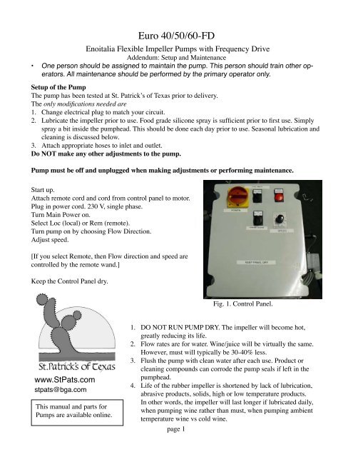
<strong>Euro</strong> 40/<strong>50</strong>/60-<strong>FD</strong><br />
Enoitalia Flexible Impeller Pumps with Frequency Drive<br />
Addendum: Setup and Maintenance<br />
• One person should be assigned to maintain the pump. This person should train other operators.<br />
All maintenance should be performed by the primary operator only.<br />
Setup <strong>of</strong> the Pump<br />
The pump has been tested at <strong>St</strong>. Patrick’s <strong>of</strong> <strong>Texas</strong> prior to delivery.<br />
The only modifications needed are<br />
. Change electrical plug to match your circuit.<br />
2. Lubricate the impeller prior to use. Food grade silicone spray is sufficient prior to first use. Simply<br />
spray a bit inside the pumphead. This should be done each day prior to use. Seasonal lubrication and<br />
cleaning is discussed below.<br />
3. Attach appropriate hoses to inlet and outlet.<br />
Do NOT make any other adjustments to the pump.<br />
Pump must be <strong>of</strong>f and unplugged when making adjustments or performing maintenance.<br />
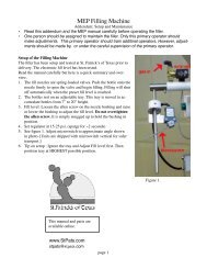
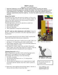
<strong>St</strong>art up.<br />
Attach remote cord and cord from control panel to motor.<br />
Plug in power cord. 230 V, single phase.<br />
Turn Main Power on.<br />
Select Loc (local) or Rem (remote).<br />
Turn pump on by choosing Flow Direction.<br />
Adjust speed.<br />
[If you select Remote, then Flow direction and speed are<br />
controlled by the remote wand.]<br />
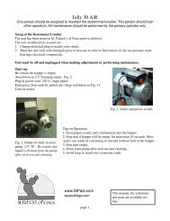
Keep the Control Panel dry.<br />
Fig. 1. Control Panel.<br />
www.<strong>St</strong>Pats.com<br />
stpats@bga.com<br />
This <strong>manual</strong> and parts for<br />
Pumps are available online.<br />
.<br />
2.<br />
3.<br />
4.<br />
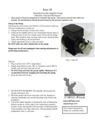
DO NOT RUN PUMP DRY. The impeller will become hot,<br />
greatly reducing its life.<br />
Flow rates are for water. Wine/juice will be virtually the same.<br />
However, must will typically be 30-40% less.<br />
Flush the pump with clean water after each use. Product or<br />
cleaning compounds can corrode the pump seals if left in the<br />
pumphead.<br />
Life <strong>of</strong> the rubber impeller is shortened by lack <strong>of</strong> lubrication,<br />
abrasive products, solids, high or low temperature products.<br />
In other words, the impeller will last longer if lubricated daily,<br />
when pumping wine rather than must, when pumping ambient<br />
temperature wine vs cold wine.<br />
page
Periodic Maintenance<br />
. Flush the pump with clean water after each use. Never leave product or chemicals in the pumphead<br />
after use.<br />
2. Lubricate the rubber impeller daily. We recomend simply spraying a bit <strong>of</strong> food-grade silicone into<br />
the pumphead. Lubrication <strong>of</strong> the impeller will extend life <strong>of</strong> the impeller.<br />
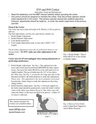
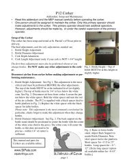
3. Clean and lubricate pumphead and impeller after every 80 hours <strong>of</strong> use (at least annually).<br />
See Fig. 2 and 3.<br />
Remove the metric allen bolts and pull <strong>of</strong> the pumphead.<br />
Pull impeller out <strong>of</strong> the pumphead. Clean pumphead and impeller---soapy water is sufficient.<br />
Lubricate the inside <strong>of</strong> the pumphead and the impeller with heavy food-grade grease.<br />
Remove the stainless steel back plate. [Tip the pump forward and tap the plate to jar it loose.]<br />
Clean shaft and all surfaces with soapy water. Lubricate all surfaces with heavy grease.<br />
Reassemble. Be careful. Do not overtighten the allen bolts. TIGHTEN LESS THAN POSSIBLE<br />
TO AVOID STRIPPING THE THREADS IN THE BOLT HOLES. Tighten in “round robin” fashion<br />
until snug. [Alternate between the bolts, tightening incrementally.] [If pumphead leaks during use,<br />
simply snug up the bolts a bit more.]<br />
4. Wipe down control box with damp cloth as needed. DO NOT CLEAN MOTOR OR ELECTRICAL<br />
BOX WITH HOSE OR PRESSURE WASHER.<br />
Fig. 2. Do NOT overtighten metric allen bolts.<br />
Fig. 3. Remove, clean, and lubricate<br />
pumphead regularly.<br />
DO NOT<br />
.<br />
2.<br />
3.<br />
4.<br />
5.<br />
DO NOT use OZONE to clean a pump. Ozone will destroy all rubber and plastic components and<br />
should NEVER be used on equipment with rubber or plastic components.<br />
DO NOT use a HOSE or PRESSURE WASHER to clean a pump. Simply wipe down with clean<br />
damp cloth. Pressure washers should NEVER be used on equipment with bearings or electrical components.<br />
DO NOT use METABISULFITE (or any harsh chemicals) for cleaning or sanitizing. Metabisulfite is<br />
not a sanitizer nor a cleaner and should NEVER be used as such. Metabisulfite is corrosive to most<br />
metals including stainless steel. The most common cause <strong>of</strong> failure <strong>of</strong> the pump seals is corrosion<br />
caused by chemicals left in the pumphead.<br />
DO NOT change parameters <strong>of</strong> the frequency drive.<br />
DO NOT RUN PUMP DRY. The impeller will become hot, greatly reducing its life.<br />
page
Special Notes for Frequency Drives<br />
1. The Frequency Drive requires about 30 seconds to power down. You cannot restart the pump during<br />
this period. Thus, if you turn <strong>of</strong>f the pump, then you must wait about 30 seconds to turn the power back<br />
on.<br />
2. GFIC (Ground Fault Interrupter Circuit) may be a problem with any Frequency Drive. If you run the<br />
pump and it trips the GFI, then you will likely need to remove the GFIC.<br />
Problems and Solutions<br />
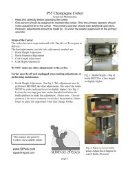
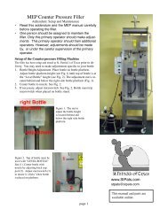
Problem: See Fig. 2. Leak at inlet or outlet TriClamp fitting. The TriClamp ferrule is threaded onto<br />
the pumphead pipe. Use pipe wrench to remove the fitting. Apply teflon tape and reassemble.<br />
Problem: See Fig 4. Leak at arrow 1. This is not a serious problem. Simply snug up the metric allen<br />
bolts (do not overtighten). If this does not solve the problem, replace the large oring. (There are 3 orings<br />
in the pumphead. Two are behind the back plate. The one in front <strong>of</strong> the back plate is the cause <strong>of</strong> a leak<br />
at arrow 1.<br />
Problem: See Fig 4. Leak at arrow 2. This is caused by defective seals and is a serious problem. Seals<br />
must be changed (see Fig. 3). This is a serious problem that can result in destruction <strong>of</strong> the motor (if the<br />
liquid makes its way into the windings <strong>of</strong> the motor.). The leak at arrow 2 is from a hole on bottom <strong>of</strong><br />
housing. This hole helps to protect the motor. If you must continue to use the pump, tip pump forward<br />
to assist with draining liquid from this hole and preventing the liquid from running back into the motor<br />
windings.<br />
The seals <strong>of</strong> the pumps will last for several years with proper care. The greatest cause <strong>of</strong> corrosion <strong>of</strong> the<br />
seals is chemicals or product left in the pumphead.<br />
Seals for pumps are available on the Enoitalia Parts page <strong>of</strong> our website.<br />
Fig. 4. Leak at Arrow 1 is minor and easily<br />
resolved by snugging up the pumphead<br />
(or changing a large oring). Leak at Arrow<br />
2 is due to corroded seals and must be<br />
resolved promptly.<br />
page
ENOITALIA S.r.l.<br />
Instructions for use and technical <strong>manual</strong><br />
“EURO” Self priming electric pumps<br />
Enoitalia S.r.l.<br />
Via Provinciale Pisana 162<br />
<strong>50</strong>0<strong>50</strong> CERRETO GUIDI - FIRENZE<br />
Tel: +39 (0)571 588031 Fax: +39 (0) 571 588080<br />
www.enoitalia.net<br />
info@enoitalia.net
E. C. DECLARATION OF COMFORMITY<br />
The firm Enoitalia S.r.l. having its registered and operative head <strong>of</strong>fice in the borough <strong>of</strong> Cerreto<br />
Guidi (FI), Pieve a Ripoli, in via Prov. Pisana 162 operating in the wine production sector as the<br />
manufacturer and retailer <strong>of</strong> the machinery :<br />
SELF PRIMING PUMPS WITH RUBBER IMPELLERS “EURO 30- 40- <strong>50</strong>-60”<br />
DECLARES<br />
That its machinery conforms to the health and safety requirements <strong>of</strong> the EEC 89/392 Machinery<br />
regulations and subsequent additions; and their conformity with regulations:<br />
EN 292-1 Sicurezza del macchinario - Concetti fondamentali, principi generali di progettazione Parte<br />
EN 292-2 Sicurezza del macchinario- Concetti fondamentali, principi generali di progettazione<br />
Parte 2: Specifiche e principi tecnici<br />
EN 294 Sicurezza del macchinario - Distanze di sicurezza per impedire il raggiungimento di zone<br />
pericolose con gli arti superiori l: Terminologia, metodologia di base<br />
EN 349 Sicurezza del macchinario - Aperture minime per evitare lo schiacciamento di parti del corpo<br />
umano<br />
EN 418 Sicurezza del macchinario - Impianto di arresto di emergenza, aspetti funzionali - Principi per<br />
la progettazione<br />
EN 953 Sicurezza del macchinario - Requisiti generali per la progettazione e la costruzione di ripari<br />
(fissi, mobili)<br />
EN 954-1 Sicurezza del macchinario - Parti dei sistemi di comando correlate alla sicurezza - Parte l:<br />
Principi generali per la progettazione<br />
EN 7346 Rumore emesso da macchine ed impianti - Metodo per la misurazione della potenza sonora.<br />
EN 60204 Impianto elettrico delle macchine - Parte l: Requisiti generali<br />
EN 60947-4-1 Interruttori e comandi a bassa tensione - Parte 4: Contattori elettromeccanici ed avvia<br />
tori di motori<br />
EN 60947-5-1 Interruttori e comandi a bassa tensione - Parte 5: Dispositivi dei circuiti di comando ed<br />
elementi di commutazione - Parte l: Dispositivi elettromeccanici dei circuiti di comando.<br />
IEC 227-1 Cavi isolati con cloruro di polivinile con voltaggi nominali fino a 4<strong>50</strong>n<strong>50</strong> v - Parte l:<br />
Requisiti generali<br />
IEC 245-1 Cavi isolati con gomma con voltaggi nominali fino a 4<strong>50</strong>/7<strong>50</strong> V- Parte 1: Requisiti generali<br />
UNI 9456 Macchine Agricole- Ripari e schermature – Definizioni e prescrizioni<br />
A <strong>manual</strong> <strong>of</strong> instructions for use is supplied with the above said machinery for its correct use and the<br />
correct performance <strong>of</strong> maintenance or repair operations without risk.
This self priming electric pump with a rubber impeller is suitable for decanting delicate liquids <strong>of</strong> an<br />
alimentary type even where particles in suspension are present (like wine, milk, oil, stemmed grapes,<br />
fruit juices), and a vast range <strong>of</strong> chemical substances.<br />
The electric pump can rotate in either direction. The main part <strong>of</strong> the pump is made entirely from AISI<br />
304 stainless steel or, upon request from AISI 316, while the impeller is made entirely from rubber for<br />
alimentary use (Certificate N° 2218 dated 05/11/98; N° 2218/b dated 05/11/98; N° 2844 dated<br />
30/11/98 in accordance with the D. M. dated 21/03/73 and D. M. n° 220 dated 26/04/93).<br />
In all the models the pump is easy to open so that normal cleaning and maintenance procedures can be<br />
carried out by qualified personnel.<br />
Some models are equipped with BY-PASS: a valve in AISI 304 stainless steel situated on the main part<br />
<strong>of</strong> the pump which enables the flow to be adjusted as desired.<br />
open<br />
open<br />
closed<br />
The electric pump is composed <strong>of</strong> the following components:<br />
-MOTOR with stainless steel shaft<br />
-TROLLEY (except for <strong>Euro</strong> 20)<br />
-PUMP SUPPORT<br />
-RUBBER IMPELLER<br />
-SHAFT IN STAINLESS STEEL AISI 304 or AISI 316 in models <strong>Euro</strong> <strong>50</strong> and <strong>Euro</strong> 60<br />
2. POSITIONING, TESTING AND INSTALLATION<br />
The electric pump should be firmly positioned on a stable surface horizontal to the ground. The level <strong>of</strong><br />
the liquid to be decanted should be at a maximum depth <strong>of</strong> not more than 5/6 metres from the center<br />
axis <strong>of</strong> the pump. The suction intake should be at least 10- 15 cm below the level <strong>of</strong> the liquid.<br />
Before installing check the following: Before plugging in the machine, confirm that the voltage <strong>of</strong> the<br />
motor (or the frequency drive) corresponds with that supplied at the mains and that the switch is turned<br />
to the OFF (0) position. The electrical safety <strong>of</strong> this machine is only guaranteed where the electrical<br />
installation has been efficiently grounded, in accordance with current regulations. Testing and any<br />
installation <strong>of</strong> necessary electrical components must be carried out by qualified personnel. The use <strong>of</strong><br />
adaptors or multiple sockets is not recommended; when they are essential only use products<br />
conforming to current safety regulations, and respect the maximum supply in terms <strong>of</strong> current and<br />
power.<br />
Attaching hoses: the hoses should be <strong>of</strong> the rigid, reinforced type and should be attached to the pump<br />
using the special adjustable metal bands, avoiding excessive tightening which would produce a<br />
restriction <strong>of</strong> the hose and prevent a steady flow <strong>of</strong> the liquid. Before turning on the machine and<br />
attaching the hoses the main part <strong>of</strong> the pump should be filled up to half its capacity with the liquid to<br />
be decanted.
IMPORTANT: never turn on the machine when empty (without any liquid in it). The first time<br />
the machine is used it should be given a preliminary wash to remove any residues which might<br />
have remained after manufacturing.<br />
3. FUNCTIONING<br />
The self priming EURO electric pumps are powered by electric motors (manufactured in the full<br />
respect <strong>of</strong> all current safety regulations), the switch <strong>of</strong> which, when the machine is <strong>of</strong>f, should always<br />
be turned to OFF or “0”<br />
To turn on the machine: turn the switch to the desired speed or to the “1” position in models where<br />
speed regulation is not provided. The intake <strong>of</strong> the pump which will suck up the liquid to be decanted,<br />
is determined by the direction <strong>of</strong> rotation <strong>of</strong> the impeller, which can be determined by observing the<br />
rotation <strong>of</strong> the fan visible at the back <strong>of</strong> the machine.<br />
Once the pump has been turned on, it should be primed in a few seconds. If more than 10 seconds pass<br />
without this happening, then you must turn <strong>of</strong>f the motor, disconnect the power supply and check that<br />
the hoses have been properly attached or that there are no holes in the feed hose since this could cause<br />
an infiltration <strong>of</strong> air.<br />
If the machine is equipped with a by-pass, then this valve can be adjusted to regulate the flow as<br />
desired, increasing it (valve closed) or decreasing it (valve open).<br />
IMPORTANT: when starting the pump, the by-pass must be closed; for the suction <strong>of</strong> solid<br />
particles the by-pass must always be closed.<br />
To turn the machine <strong>of</strong>f just turn the switch to “OFF” or “0”<br />
In the event <strong>of</strong> an emergency stop then turn the machine on again in the opposite direction then<br />
immediately invert the direction so as to eliminate particulates which might hinder the rotation <strong>of</strong> the<br />
impeller.<br />
4.WASHING AND MAINTENANCE<br />
After use, the machine should be washed so as to maintain its mechanical and hygienic features. Allow<br />
the machine to operate for a few minutes with clean water, then empty the hoses and the main part <strong>of</strong><br />
the pump completely <strong>of</strong> any water. If you do not plan to use the pump for some time, then pour a few<br />
drops <strong>of</strong> glycerine oil (or food grade lubricant) into the pump before turning it on for a few seconds.<br />
Maintenance: all the parts <strong>of</strong> the pump are checked and adjusted in the factory before packing. For this<br />
reason the machine doe snot require any special maintenance, but just needs periodic checks which will<br />
also make it last longer.<br />
IMPORTANT: Such periodic inspections should be carried out by qualified personnel with the<br />
machine unplugged.<br />
The following aspects should be checked:<br />
• wear and tear <strong>of</strong> the impeller<br />
• check sealing orings<br />
• check bearings<br />
In the event repairs are necessary, only use original spare parts ordered from the retailer or directly<br />
from the manufacturer.
Possible causes <strong>of</strong> malfunctioning<br />
PROBLEM<br />
REMEDY<br />
The pump isn’t exerting enough pressure Check the state <strong>of</strong> wear and tear <strong>of</strong> the impeller.<br />
Liquid is leaking from the main part <strong>of</strong> the pump Check and if necessary replace the sealing orings<br />
Liquid is leaking from the flange <strong>of</strong> the motor or Check and if necessary replace the sealing orings<br />
the support <strong>of</strong> the pump<br />
Breakage <strong>of</strong> one or more fins <strong>of</strong> the impeller Replace the impeller with an original spare part<br />
ordered from the retailer or directly from the<br />
manufacturer<br />
It’s difficult to get the machine started. Check that the machine is getting enough power<br />
from the mains. Don’t use extension cords which<br />
might cause a lowering <strong>of</strong> the voltage.<br />
5. WARNINGS<br />
• <strong>St</strong>ore the machine in a dry place, where it is not exposed to bad weather and protect it from getting<br />
damp<br />
• Do not use the machine for decanting inflammable or explosive liquids or in an explosive<br />
environment, since the motor is not anti-deflagration.<br />
• The temperature <strong>of</strong> the liquids being decanted should be between +5 °C and 65 °C; higher<br />
temperatures would compromise the general performance <strong>of</strong> the impeller.<br />
• Before turning on the machine check that it has not been damaged during transport (breakage or<br />
dents).<br />
• Never plug it in, turn it on or perform any other operation on the electrical parts with wet hands<br />
• Do not remove the protective guard (on the models where it is provided) while the machine is in use,<br />
or while washing<br />
• Before using the machine carefully read this <strong>manual</strong>, and keep it safely for future reference<br />
• The firm Enoitalia S.r.l. is not liable for damage deriving from modifications made by others to the<br />
machinery.<br />
• The firm Enoitalia S.r.l. reserves the right to make manufacturing modifications at any moment<br />
without being obliged to make these public.
ENOITALIA s.r.l.<br />
COSTRUZIONI MECCANICHE Via Prov.le Pisana 162 –<br />
<strong>50</strong>0<strong>50</strong> PIEVE A RIPOLI – CERRETO GUIDI (FI)<br />
Tel. 0571 588031 Fax. 0571 588080<br />
C.F. e P. IVA 0398759 048 0<br />
www.enoitalia.net – E-mail: info@enoitalia.net<br />
LISTA COMPONENTI: POMPA MOD. EURO <strong>50</strong> MVE<br />
Pos. Q. Descrizione Cod.<br />
1 1 Scatola comandi e inverter E 54<br />
2 1 Comandi remoti E 55<br />
3 1 Motore elettrico ME <strong>50</strong><br />
4 1 Cuscinetto R <strong>50</strong><br />
5 1 Flangia E 53<br />
6 1 Or G 2157<br />
7 1 Or G 3212<br />
8 1 Tenuta meccanica parte fissa G 96230<br />
9 1 Tenuta meccanica parte rotante G 91541<br />
10 1 Seeger S <strong>50</strong><br />
11 1 Disco E 52<br />
12 1 Girante gomma E 51<br />
13 1 Or G 2157<br />
14 1 Corpo pompa E <strong>50</strong><br />
15<br />
16<br />
17<br />
17bis<br />
18<br />
19<br />
20
220V - <strong>50</strong>i12<br />
J.IJ<br />
N<br />
(D<br />
r<br />
I<br />
En<br />
-irz!s!-<br />
Aatt<br />
-(,<br />
OB<br />
. . . . . . . . . . . t . . . .. . . . . :<br />
r €' . l<br />
P F<br />
- - i - ><br />
l r E<br />
3 . r 8<br />
N)<br />
ievr<br />
I SA5<br />
+ r \ / J-*<br />
tloa<br />
CCW<br />
-a<br />
tlD<br />
*o<br />
l l<br />
sAsl<br />
. ' \ ' I<br />
F - \ - - - - - +<br />
J l )<br />
l<br />
t l l<br />
t t : :<br />
' ' ' . . : - :<br />
Faa ;<br />
:<br />
6 " '<br />
LOC / RErl<br />
0rl<br />
<br />
t!<br />
(o<br />
!<br />
(t<br />
@<br />
@<br />
ilM@ffi<br />
vl 000<br />
OMG<br />
!T.Ii/. FAULT<br />
m z<br />
O<br />
-t<br />
D<br />
t-<br />
D<br />
il<br />
o<br />
C T<br />
gJ<br />
il<br />
r<br />
I.IAIII POWER SUPPLY<br />
22Ot/-6gHi<br />
WI.}JE PU.IIP<br />
LOCAL PUMP SPT}.D REC. REilIOTE PU,VP SPEID REG<br />
zHP _ gDORP),I 104<br />
ENIOIIALIA s.r.l.<br />
MlrCCtIINf, E'T{Ol,oClCSs - I'!NE II.{KING bIACEINES<br />
5OD5O PIETE A RIPOU.CERRETO GUIDI_IT{Y<br />
rBL- O7l 588081<br />
FA.Y 'aBOEo<br />
ors. r,r. , 36405<br />
rfAccHlNAy'ttACHDtE l1:'*^, -"<br />
SINELE PHAST PUMP TONTROL PANEL<br />
T<br />
D<br />
c'