J2 225 MSR - Size
J2 225 MSR - Size
J2 225 MSR - Size

Create successful ePaper yourself
Turn your PDF publications into a flip-book with our unique Google optimized e-Paper software.
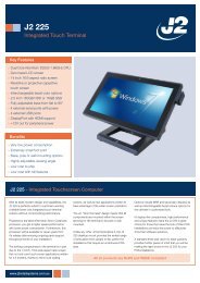
<strong>J2</strong> <strong>225</strong> Integrated Touch Screen Computer<br />
System Manual<br />
April 2012
Copyright © 2012 <strong>J2</strong> Retail Systems Ltd<br />
All rights reserved<br />
Change history<br />
Version 1.0 Release May 29, 2012<br />
<strong>J2</strong> <strong>225</strong> System Manual<br />
Version 1.0 May 29, 2012<br />
2
Contents<br />
Overview ............................................................................................................................ 6<br />
Design Concept <strong>J2</strong> <strong>225</strong> ...................................................................................................... 8<br />
Specifications <strong>J2</strong> <strong>225</strong> ......................................................................................................... 9<br />
<strong>J2</strong> <strong>225</strong> Integrated Touch Screen Computer .................................................................. 10<br />
I/O Ports ........................................................................................................................ 10<br />
Off / On Button ............................................................................................................. 10<br />
Hard Disks .................................................................................................................... 11<br />
Touch Screen ................................................................................................................ 11<br />
System Board ................................................................................................................ 12<br />
<strong>J2</strong> <strong>225</strong> Display ............................................................................................................... 12<br />
Secondary Video Port ................................................................................................... 13<br />
Serial ports .................................................................................................................... 14<br />
USB Ports ...................................................................................................................... 16<br />
Ethernet Connection ...................................................................................................... 16<br />
Audio ............................................................................................................................. 17<br />
Cash Drawer Ports ........................................................................................................ 17<br />
CMOS Clear .................................................................................................................. 19<br />
Mini PCI-E .................................................................................................................... 19<br />
Memory SODIMM(s) ................................................................................................... 20<br />
Power Supply ................................................................................................................ 20<br />
+12VDV Power Out ..................................................................................................... 21<br />
Typical Power Consumption <strong>J2</strong> <strong>225</strong> ............................................................................. 21<br />
Service .............................................................................................................................. 22<br />
Swing Arm Base ........................................................................................................... 22<br />
Removing the Power Supply ........................................................................................ 23<br />
Cable Routing ............................................................................................................... 24<br />
VESA Mounting ........................................................................................................... 26<br />
<strong>J2</strong> <strong>225</strong> Disassembly Instructions ................................................................................... 27<br />
BIOS Setting .................................................................................................................... 33<br />
Main Screen .................................................................................................................. 33<br />
System Information ....................................................................................................... 33<br />
Advanced Screen .......................................................................................................... 34<br />
Boot Configuration ....................................................................................................... 34<br />
Power Configuration ..................................................................................................... 35<br />
COM Power and LCD Brightness Configuration ......................................................... 35<br />
Security Screen ............................................................................................................. 36<br />
Boot Screen ................................................................................................................... 36<br />
Exit Screen .................................................................................................................... 37<br />
Phoenix Secure Core Tiano BIOS ................................................................................ 37<br />
<strong>J2</strong> <strong>225</strong> System Manual<br />
Version 1.0 May 29, 2012<br />
3
Device Drivers ................................................................................................................. 37<br />
OPOS Drivers .................................................................................................................. 37<br />
<strong>J2</strong> <strong>225</strong> Configuration Utility .......................................................................................... 38<br />
Installation ..................................................................................................................... 38<br />
Main .............................................................................................................................. 38<br />
Power-On Hours ........................................................................................................... 39<br />
Power Cycles ................................................................................................................ 39<br />
Dim Timeout ................................................................................................................. 39<br />
Dim Brightness ............................................................................................................. 40<br />
Basic <strong>MSR</strong> Settings ...................................................................................................... 41<br />
Advanced <strong>MSR</strong>/iButton Settings .................................................................................. 42<br />
Update MCU Firmware ................................................................................................ 44<br />
MCU Option ................................................................................................................. 45<br />
DimWake ......................................................................................................................... 46<br />
Installation ..................................................................................................................... 46<br />
<strong>J2</strong> Health .......................................................................................................................... 47<br />
Installation ..................................................................................................................... 47<br />
Tray Icon ....................................................................................................................... 47<br />
Logging to File .............................................................................................................. 48<br />
Registry Entries ............................................................................................................. 49<br />
<strong>J2</strong> Remote Monitoring Software ................................................................................... 49<br />
SMI BIOS Info Utility .................................................................................................... 50<br />
Installation ..................................................................................................................... 50<br />
Operations ..................................................................................................................... 50<br />
Cash Drawer Test Utility ................................................................................................ 51<br />
Installation ..................................................................................................................... 51<br />
Operation ....................................................................................................................... 51<br />
<strong>J2</strong> Virtual Serial Ports Drivers ...................................................................................... 53<br />
<strong>J2</strong> <strong>225</strong> Options ................................................................................................................. 54<br />
<strong>J2</strong> <strong>225</strong> LCM 2x20 Character Customer Display .......................................................... 54<br />
Installation ..................................................................................................................... 55<br />
<strong>J2</strong> <strong>225</strong> LCM Configuration Utility ............................................................................... 57<br />
Installation ..................................................................................................................... 57<br />
<strong>J2</strong> <strong>225</strong> <strong>MSR</strong> ...................................................................................................................... 60<br />
Installation ..................................................................................................................... 61<br />
<strong>J2</strong> <strong>225</strong> System Manual<br />
Version 1.0 May 29, 2012<br />
4
<strong>J2</strong> <strong>225</strong> iButton Reader .................................................................................................... 63<br />
Installation ..................................................................................................................... 64<br />
<strong>J2</strong> <strong>225</strong> Wall Mount / Counter-top Mount Kit .............................................................. 66<br />
Packing list .................................................................................................................... 66<br />
Assembly ....................................................................................................................... 67<br />
<strong>J2</strong> <strong>225</strong> 10.1 inch 1024 x 600 LCD Customer Display ................................................... 71<br />
Installation ..................................................................................................................... 72<br />
Contact Information ....................................................................................................... 75<br />
European Office ............................................................................................................ 75<br />
USA Office ................................................................................................................... 75<br />
Australian Office ........................................................................................................... 75<br />
Website ......................................................................................................................... 75<br />
<strong>J2</strong> <strong>225</strong> System Manual<br />
Version 1.0 May 29, 2012<br />
5
Overview<br />
The <strong>J2</strong> <strong>225</strong> is a new generation of integrated touch screen Point of Sale computer,<br />
brilliantly designed to be more compact and cost effective, yet rich in features and<br />
versatility. The <strong>J2</strong> <strong>225</strong> moves away from the traditional POS 4:3 screen form factor and<br />
uses the newer LED backlit 16:9 screen. This allows for a smaller overall physical<br />
footprint yet allows for the display of more onscreen data. Retaining the core features and<br />
capabilities of <strong>J2</strong>’s other tradition POS products, like the <strong>J2</strong> 615 and <strong>J2</strong> 630 units, the <strong>J2</strong><br />
<strong>225</strong> takes advantage of the newer technologies currently available.<br />
This integrated touch screen computer, like other <strong>J2</strong> designs, features an “all-in-the-head”<br />
design, and it also offers the versatility to be used as a counter top unit; or as a wallmount<br />
or pole-mounted terminal. The new smaller foot print and its unique swing arm,<br />
die cast aluminum base allows for even more flexibility, leaving more counter space for<br />
other uses. With an extremely wide range of adjustable heights and viewing angles, the<br />
versatile <strong>J2</strong> <strong>225</strong> can be made to work in almost any POS environment. It weighs only<br />
3.7kg and conveniently folds flat for shipping, therefore saving customers tremendously<br />
on shipping and storing costs.<br />
The <strong>J2</strong> <strong>225</strong> uses the latest Intel Atom dual core Cedarview processors, the 1.86GHz<br />
D2550. Combining this with the Intel NM10 chipset provides excellent performance<br />
capable of running most POS applications with a very low carbon foot print, all at a<br />
competitive and attractive low price.<br />
Even with its small foot print the <strong>J2</strong> <strong>225</strong> is incredibly feature rich. It comes standard with<br />
2GB of memory, and offers a choice of either a 160GB hard drive or 16GB solid state<br />
drive. Built standard with four serial ports, four USB ports, video output, audio in/out,<br />
gigabit Ethernet, +12V output, as well as other built in peripherals (like <strong>MSR</strong>, customer<br />
display and more) the <strong>J2</strong> <strong>225</strong> will perfectly satisfy most POS application requirements,<br />
while looking sleek and elegant in any setting.<br />
The <strong>J2</strong> <strong>225</strong> is available with your choice of either a zero bezel resistive touch screen or a<br />
multi-touch projected capacitive touch screen. The new zero bezel five-wire resistive<br />
touch screen provides the same quick response and feel of a resistive touch screen<br />
traditionally used in the POS market. The new projective capacitive touch screen option<br />
can be used in environments where multi-touch and gesturing are required, for example,<br />
such as when using the new Windows 8 operating system.<br />
The <strong>J2</strong> <strong>225</strong> is brilliantly designed to require little or no maintenance. The convection<br />
cooled fan-less design means it can be used in very harsh environments. High dust,<br />
grease or sea air will not affect its operation. High temperatures are also not a problem.<br />
With a quick access HDD/SDD slot, a drive can be changed in just seconds if needed! A<br />
snap-apart design allows the unit to be fully disassembled and assembled in just a few<br />
minutes by just removing a few screws. Also available are optional Snap-on color kits, so<br />
that the <strong>J2</strong> <strong>225</strong> can be customized to your customer needs.<br />
<strong>J2</strong> <strong>225</strong> System Manual<br />
Version 1.0 May 29, 2012<br />
6
The <strong>J2</strong> <strong>225</strong> supports the standard Microsoft operating systems: Windows 7, POSReady 7,<br />
Windows 7 Embedded, XP, POSReady 2009 and XP embedded, as well as the soon-tobe-released<br />
Windows 8. The <strong>J2</strong> <strong>225</strong> is equally proficient with the many flavors of Linux.<br />
<strong>J2</strong> <strong>225</strong> System Manual<br />
Version 1.0 May 29, 2012<br />
7
Design Concept <strong>J2</strong> <strong>225</strong><br />
The <strong>J2</strong> <strong>225</strong>, with its smooth modern appearance and capabilities, is perfectly suited for<br />
most low cost commodity POS touch screen computer markets. The economical price and<br />
outmatched performance will provide a great ROI for the end user, as they find it<br />
extremely dependable as well as very easy to use. <strong>MSR</strong> and Secondary Display options<br />
make it a perfect fit for companies in the POS markets, as well as for other industries,<br />
including medical and healthcare applications, among many others.<br />
To provide the highest performance at low cost with a long product life the <strong>J2</strong> <strong>225</strong> unit<br />
design is based on the new Intel Atom Cedarview processor. This new 32nm part has<br />
higher speed and runs on lower power than the current offering of Atom processors for<br />
Intel.<br />
The unit was built using as few screws as possible, providing ease of assembly and<br />
disassembly, a major design achievement. This means that the touch screen, <strong>J2</strong> <strong>225</strong> panel,<br />
or systems board can quickly be replaced in less than two minutes if needed (however<br />
with the solid reliability of this creative unit, this should not even be necessary.)<br />
A major goal in the enclosure design is to keep the total size of the unit as thin and as<br />
small as possible. The thickness to the head is not much thicker that a standard notebook,<br />
except for a slight bulge in the back where the electronics are located. The aluminum die<br />
cast swing arm and fully adjustable base of the unit not only provide superb flexibility but<br />
can also easily fold flat for shipping. The shipping box for the <strong>J2</strong> <strong>225</strong> is no bigger than<br />
the size of an average notebook shipping box, which is also about 1/3 to 1/4 the size and<br />
weight of other POS products.<br />
As with all <strong>J2</strong> products our ultimate goal is always reliability. Reliability is never<br />
compromised because to reduce any cost at the expense of a dependable product would<br />
be a false economy, and we firmly stand by our outstanding engineering and designs. We<br />
always have our customer’s needs in mind as we move forward, offering the best in the<br />
market today.<br />
<strong>J2</strong> <strong>225</strong> System Manual<br />
Version 1.0 May 29, 2012<br />
8
Specifications <strong>J2</strong> <strong>225</strong><br />
CPU and Chipset<br />
Processor<br />
Chipset I/O<br />
Memory<br />
External Ports<br />
Serial Ports<br />
Dual Core Intel Atom D2550 1.86GHz with 1MB Cache, 4 threads<br />
with Integrated GMA 3650 Graphics controller<br />
NM10<br />
2 X DDR3 SO-DIMM, 4GB max, 2GB standard, 1067MHz<br />
4 RS-232 RJ45 with power +12V BIOS controlled<br />
USB Ports 4 USB 2.0<br />
Ethernet<br />
Cash Drawer Ports<br />
Secondary Video<br />
10/100/1000 MHz Ethernet port with status LEDs on connector<br />
1 RJ11 support 2 cash drawers +24V and +12V, Dual status lines<br />
Display Port with DVI, HDMI and VGA support<br />
+12 Power +12 Volt power out for secondary video display or other device<br />
Audio<br />
Internal I/O<br />
Storage<br />
<strong>J2</strong> <strong>225</strong> Display<br />
LED backlight<br />
Touch Screen<br />
USB<br />
<strong>MSR</strong><br />
Serial<br />
Mini PCI-Express<br />
Optional Peripherals<br />
<strong>MSR</strong><br />
iButton<br />
Fingerprint Reader<br />
Customer Display<br />
Secondary Video<br />
Wireless<br />
Combo Audio Jack for headset or headset with microphone<br />
One 3Gb/s SATA Port onboard, slide in/out 2.5“ HDD or SSD<br />
14.0 inch 16:9 LVDS 1366x768 panel<br />
LED backlight power with auto dimming control<br />
Resistive True Flat or Projective Capacitive with Multi-touch and gesturing<br />
4 onboard USB ports for optional devices, <strong>MSR</strong>, Wi-Fi, PCT<br />
Onboard microcontroller of <strong>MSR</strong> on PS2<br />
Serial port header for optional customer display or other option<br />
Mini PCI Express slot for 802.11 b/g/n WiFi card and other functions<br />
Slim line <strong>MSR</strong>, Keyboard Wedge or virtual serial<br />
iButton module, Keyboard Wedge or virtual serial<br />
Digital Persona module, attached to front bottom of display head<br />
<strong>J2</strong> <strong>225</strong> 2x20 customer display, Serial<br />
10 inch 1024x600 16:9 <strong>J2</strong> <strong>225</strong> Secondary Display internal connection<br />
802.11 b/g/n Mini PCI Express card with internal antennaes<br />
Environmental<br />
Operating Temp. 0-40c<br />
EMI<br />
Safety<br />
Dust & Water<br />
Power<br />
Weight<br />
Dimensions<br />
CE / FCC Class A<br />
LVD external adaptor UL c/us, CE, TUV, others<br />
IP 64 front of unit, IP 54 whole unit<br />
100-240V 50-60Hz 19VDC 65 watts power supply<br />
Head 2.5kg, Base 1.4kg, gross shipping weight 6kg<br />
With base attached and folded: 360x260x80mm, 14.2”x10.2”x3.14”<br />
System max height unfolded: 280mm, 11”<br />
<strong>J2</strong> <strong>225</strong> System Manual<br />
Version 1.0 May 29, 2012<br />
9
<strong>J2</strong> <strong>225</strong> Integrated Touch Screen Computer<br />
I/O Ports<br />
Most I/O ports are accessible in the cable well at the bottom of the unit. Cables are routed<br />
though the cable channel in the swing arm base. (See Cable Routing)<br />
I/O Panel<br />
Off / On Button<br />
The Off /On button is located in the cable well, as shown below. This button is located<br />
near the side to prevent accidental powering down by the user. The function of the button<br />
can be controlled by the OS. If the <strong>J2</strong> <strong>225</strong> hangs for some reason it can always be<br />
powered off by holding the Off /On button in for six seconds.<br />
The <strong>J2</strong> <strong>225</strong> also supports the following: Restore on AC on power loss, Wake On LAN,<br />
and Wake On RTC alarm features to control the system power up. The setting for these<br />
features is controlled from the BIOS.<br />
Off / On Button Location<br />
<strong>J2</strong> <strong>225</strong> System Manual<br />
Version 1.0 May 29, 2012<br />
10
Hard Disks<br />
One 2.5 inch SATA hard drive (HDD) or a solid state drive (SSD) are standard with the<br />
<strong>J2</strong> <strong>225</strong>. The SATA interface can support data transfer rates up to 3.0 GB/s. The <strong>J2</strong> <strong>225</strong><br />
offers standard either a 160GB HDD or 16GB SSD, but can be ordered with other size<br />
HDD or SSD as well. See <strong>J2</strong> for details.<br />
The HDD/SSD can be installed or removed in seconds by removing one screw. It is<br />
easily accessed by removing the HDD cover retaining screw and sliding the drive out, the<br />
HDD cover can then be unclipped from the drive.<br />
HDD access panel<br />
HDD slide in-slide out drive bay<br />
Touch Screen<br />
The <strong>J2</strong> <strong>225</strong> can be ordered with two different touch screen technologies, PCT or TFR.<br />
The PCT unit uses a multi-touch Projected Capacitive Technology touch screen. The PCT<br />
touch screen has no known failure mode-- it does not “wear out.” This screen is<br />
tempered glass and does not reduce the brightness of the <strong>J2</strong> <strong>225</strong> panel. When operating<br />
in a very high use environment, the PCT is the recommended touch screen technology.<br />
The PCT touch screen will work with most gloves and stylus that are designed to work<br />
with tablet computers, and the screen has a smooth glass surface that is reflective.<br />
The TFR uses a five-wire true flat (zero bezel) resistive touch screen rated at 35 million<br />
touches per point. The resistive technology is very responsive and is the traditional choice<br />
for a hospitality POS system. The screen has an anti-reflective plastic film surface.<br />
Both screens are fully spill proof, dust proof, and can be cleaned with a standard glass<br />
cleaner. The <strong>J2</strong> <strong>225</strong> touch screen was designed to easily be changed, normally in less than<br />
two minutes. Depending on operating environment and usage, both the Resistive and<br />
PCT touch screens have strengths and weaknesses; therefore <strong>J2</strong> offers both touch screen<br />
technologies on the <strong>J2</strong> <strong>225</strong> unit, providing our customers with a choice for any<br />
application requirement.<br />
<strong>J2</strong> <strong>225</strong> System Manual<br />
Version 1.0 May 29, 2012<br />
11
System Board<br />
POS computers typically have a lifespan of 10 years or longer, therefore product quality<br />
is of the utmost importance. <strong>J2</strong> <strong>225</strong> electronics are built with high-end components to<br />
ensure reliability and long lasting product performance.<br />
The system board is designed for quick replacement, with just a few screws and cables to<br />
unplug. The board can be swapped out in less than three minutes.<br />
<strong>J2</strong> <strong>225</strong> System board<br />
<strong>J2</strong> <strong>225</strong> Display<br />
The <strong>J2</strong> <strong>225</strong> offers a 1366 x 768 resolution display with 16.2 Million colors, and a 14 inch<br />
LED backlight with 16:9 aspect ratio screen. The brightness is rated at 220cd/m 2 . The<br />
Intel controller allows for the display to be rotated to 0, 90, 180 or 270 degrees without<br />
loss of performance. The driver can also scale the display resolution so that it can work<br />
properly with applications written for 1024x768 or 800x600 resolutions.<br />
The <strong>J2</strong> <strong>225</strong> electronics also supports dimming, and can be controlled directly by<br />
Windows 7 or 8, or with <strong>J2</strong> supplied utilities for Windows XP. Dimming levels between<br />
5-100% are supported. A hardware auto dimming feature is built-in to ensure the longest<br />
LED backlight life and to also provide the lowest power usage.<br />
<strong>J2</strong> <strong>225</strong> System Manual<br />
Version 1.0 May 29, 2012<br />
12
Secondary Video Port<br />
The <strong>J2</strong> <strong>225</strong> supports the newer digital video standard Display Port connector. This<br />
connector supports a Display Port monitor, HDMI display, DVI or VGA monitor. When<br />
used with HMDI or DVI displays, a passive adaptor cable must be used. When using a<br />
VGA display, an active adaptor is to be used. With HDMI display Audio, support is<br />
provided via the same HMDI cable.<br />
The secondary video displays can be configured as Twin, Intel Dual Display Clone, or<br />
Extended Desktop. Most all monitor resolutions from 640 x 480, up to 2560 x 1600 are<br />
supported.<br />
When the internal secondary <strong>J2</strong> <strong>225</strong> video display is used the secondary video port is not<br />
available.<br />
DisplayPort Video Port<br />
<strong>J2</strong> <strong>225</strong> System Manual<br />
Version 1.0 May 29, 2012<br />
13
Serial ports<br />
The <strong>J2</strong> <strong>225</strong> unit has four external RS232 serial ports, all of which can supply +12V<br />
power. The serial ports use a ten pin RJ45 connector. The unit comes standard with four<br />
serial cables, three 38cm (15”) RJ45 to DB9 adapter cables, and one 152cm (5’) RJ45 to<br />
DB25 serial printer cable that works with EPSON and EPSON compatible printers.<br />
All serial (COM) ports can be BIOS-enabled to provide +12Vpower to external devices.<br />
This power is supplied via pin 10 of the RJ45 which corresponds to pin 9 on the DB9<br />
adaptor. The maximum current per port is 1 amp, with a total maximum external loading<br />
on the +12V of 3 amps.<br />
A set of stick-on color coded labels are supplied with the cable adaptors, so that the<br />
cables can be marked. This makes it easy to plug the cable back into the correct port,<br />
should you need to service the unit.<br />
Serial Ports<br />
BIOS Setting Serial Port(s) Power Enable<br />
<strong>J2</strong> <strong>225</strong> System Manual<br />
Version 1.0 May 29, 2012<br />
14
RJ45 to DB9 <strong>J2</strong> Adaptor Cable Pin-Out when using CAT5/6 Cable<br />
RJ45-10 Pin DB9 Signal RJ45- 8 Pin DB9 Signal<br />
Pin 1 --- --- --- --- ---<br />
Pin 2 Pin 1 DCD Pin 1 Pin 1 DCD<br />
Pin 3 Pin 6 DSR Pin 2 Pin 6 DSR<br />
Pin 4 Pin 2 RD Pin 3 Pin 2 RD<br />
Pin 5 Pin 7 RTS Pin 4 Pin 7 RTS<br />
Pin 6 Pin 3 SD Pin 5 Pin 3 SD<br />
Pin 7 Pin 8 CTS Pin 6 Pin 8 CTS<br />
Pin 8 Pin 4 DTR Pin 7 Pin 4 DTR<br />
Pin 9 Pin 5 GND Pin 8 Pin 5 GND<br />
Pin 10 Pin 9 RI --- --- ---<br />
The <strong>J2</strong> Cable Adaptor (supplied)<br />
RJ45 to DB25 <strong>J2</strong> Serial Pinter Cable Pin-out when using 8 wire CAT5/6 cable<br />
RJ45-10 Pin Signal DB25 Signal RJ45- 8 Pin Signal DB25 Signal<br />
Pin 1 --- --- --- --- --- --- ---<br />
Pin 2 DCD --- --- Pin 1 DCD --- ---<br />
Pin 3 DSR Pin 20 DTR Pin 2 DSR Pin 20 DTR<br />
Pin 4 RD Pin 2 SD Pin 3 RD Pin 2 SD<br />
Pin 5 RTS Pin 5 CTS Pin 4 RTS Pin 5 CTS<br />
Pin 6 SD Pin 3 RD Pin 5 SD Pin 3 RD<br />
Pin 7 CTS Pin 4 RTS Pin 6 CTS Pin 4 RTS<br />
Pin 8 DTR Pin 6 DSR Pin 7 DTR Pin 6 DSR<br />
Pin 9 GND Pin 7 GND Pin 8 GND Pin 7 GND<br />
Pin 10 --- --- --- --- --- --- ---<br />
Epson or Epson compatible serial printer cable<br />
<strong>J2</strong> <strong>225</strong> System Manual<br />
Version 1.0 May 29, 2012<br />
15
USB Ports<br />
The <strong>J2</strong> <strong>225</strong> has 4 external and 4 internal USB 2.0 ports. The 4 external ports (see below)<br />
are located in the cable well. The 4 internal ports are used for different functions, such as<br />
using a PCT touch screen, RFID reader and/or other peripherals.<br />
USB Ports<br />
Ethernet Connection<br />
The <strong>J2</strong> <strong>225</strong> uses the Realtek RTL8111 Gigabit Ethernet controller. The Ethernet<br />
connector is located in the cable well, as shown below. The Ethernet controller supports<br />
Wake on LAN, and the BIOS supports a PXE boot ROM as well. There is a LED on the<br />
LAN connector, this Green LED light turns on when there is LAN activity.<br />
Ethernet Connector<br />
<strong>J2</strong> <strong>225</strong> System Manual<br />
Version 1.0 May 29, 2012<br />
16
Audio<br />
The <strong>J2</strong> <strong>225</strong> uses the VIA1708B HD audio controller. There is one internal speaker.<br />
A combo microphone jack and headset jack are located in the cable well of the <strong>J2</strong> <strong>225</strong>, as<br />
seen below, which allows for the connection of a microphone and headset, or audio out to<br />
other devices.<br />
Audio out is also supported on the DisplayPort when used with a HDMI monitor.<br />
Audio Jack Location<br />
Cash Drawer Ports<br />
The <strong>J2</strong> <strong>225</strong> is equipped with one Cash Drawer port that can support one or two drawers.<br />
This port is located in the cable well, and uses the industry standard RJ-11 connector and<br />
pin-out (illustrated below).<br />
Cash Drawer Ports<br />
<strong>J2</strong> <strong>225</strong> System Manual<br />
Version 1.0 May 29, 2012<br />
17
Cash Drawer 1 Pin Assignment<br />
6 1<br />
Pin<br />
Signal<br />
1 GND<br />
2 CD1 SOLENOID<br />
3 STATUS / STATUS CD1<br />
4 24V<br />
5 CD2 SOLENOID<br />
6 GND / STATUS CD2<br />
The application may address the Cash Drawer port in two ways:<br />
1) Using the <strong>J2</strong>-supplied OPOS drivers for Windows.<br />
2) Direct access to the I/O ports<br />
Cash Drawer Controller Register<br />
The Cash Drawer Controller use one I/O address to control the Cash Drawer.<br />
Register Location: 48Ch<br />
Attribute: Read / Write<br />
<strong>Size</strong>: 8bit<br />
BIT BIT7 BIT6 BIT5 BIT4 BIT3 BIT2 BIT1 BIT0<br />
Attribute Read Reserved Write Reserved<br />
7 6 5 4 3 2 1 0<br />
X X X X<br />
Reserved<br />
Cash Drawer 1 fire<br />
Cash Drawer 2 fire<br />
Reserved<br />
Cash Drawer 1 status<br />
Cash Drawer 2 status<br />
The “Y” cable used to support two cash drawers on the one RJ-11 is the same as is used<br />
on Epson printers.<br />
<strong>J2</strong> <strong>225</strong> System Manual<br />
Version 1.0 May 29, 2012<br />
18
CMOS Clear<br />
The <strong>J2</strong> <strong>225</strong> CMOS can be cleared by unplugging the system board CMOS battery for 30<br />
seconds before plugging it back in.<br />
CMOS Battery<br />
Mini PCI-E<br />
The onboard Mini PCI Express connector is normally used for the optional internal<br />
802.11b/g/n wireless LAN card.<br />
Mounting Screw<br />
<strong>J2</strong> <strong>225</strong> System Manual<br />
Version 1.0 May 29, 2012<br />
19
Memory SODIMM(s)<br />
The <strong>J2</strong> <strong>225</strong> supports two SODIMM DDR3 memory sockets. The unit comes standard<br />
with 2GB of main memory and can support up to a maximum of 4GB. The memory type<br />
is DDR3 800/1066.<br />
Power Supply<br />
The <strong>J2</strong> <strong>225</strong> uses a notebook-type power supply that is mounted in the base of the unit.<br />
The power supply is rated with an output of 65 watts 18.5 VDC 3.5 Amps, and has an<br />
input rating of 100-240VAC at 50~60Hz 1.7Amps maximum. The power supply has an<br />
efficiency rating V. The power supply connector is a standard notebook locking type that<br />
plugs into the system power input connector, located in the cable well.<br />
Power Input connector<br />
<strong>J2</strong> <strong>225</strong> System Manual<br />
Version 1.0 May 29, 2012<br />
20
+12VDV Power Out<br />
The <strong>J2</strong> <strong>225</strong> has a fused power out connector that supplies a total of 12VDC, up to 2amp.<br />
The power supply connector is a standard notebook locking type that plugs into the<br />
system power input connector, located in the cable well, seen below<br />
Power Input connector<br />
Typical Power Consumption <strong>J2</strong> <strong>225</strong><br />
The typical power consumption of the <strong>J2</strong> <strong>225</strong> is lower than a notebook computer and more<br />
comparable to a netbook computer. Using the latest generation Intel’s Atom processor and<br />
chipset allows for much lower power consumption than previous generations of POS computers.<br />
When coupled with the proper system configuration, this can greatly reduce the system total<br />
carbon foot print.<br />
Test conditions<br />
Voltage:<br />
220VAC 50Hz, measured voltage 236 VAC<br />
OS: POSReady 7<br />
Heavy Load Program: PassMark BurnInTest defaults values<br />
Maximum load: PassMark BurnInTest Max CPU Temp<br />
Temperature: 26c<br />
All systems are tested in their standard hard drive configuration. Results are +/- 15%.<br />
<strong>J2</strong> <strong>225</strong> D2550 1.86GHz<br />
1: Normal application including most POS software 23 watts<br />
2: Very heavy load application 26 watts<br />
3: Maximum load 29 watts<br />
4: Normal POS app, backlight dimmed 20 watts<br />
4: Normal POS app, backlight off 18 watts<br />
5: Standby, unit off, waiting for wake on LAN, RTC or power button >4 watts<br />
<strong>J2</strong> <strong>225</strong> System Manual<br />
Version 1.0 May 29, 2012<br />
21
Service<br />
Swing Arm Base<br />
The <strong>J2</strong> <strong>225</strong> is shipped standard with a counter top base which allows for the head to be<br />
adjusted from 0-100°, and the height can be from 8cm to 28. This allows for great<br />
versatility in height and viewing angles.<br />
The <strong>J2</strong> <strong>225</strong> swing arm base can be folded down flat for shipping, or it can also be used<br />
with the wall mounting option. Being able to fold flat greatly reduces the size of the<br />
shipping box, thereby reducing its shipping cost and storage space. When using the<br />
optional wall mount bracket, the base can be attached and allow for an adjustable viewing<br />
angle.<br />
<strong>J2</strong> <strong>225</strong> System Manual<br />
Version 1.0 May 29, 2012<br />
22
The base has a lock-down screw hole to secure the base to the counter top with just a<br />
screw, or it can be attached using the wall mount bracket.<br />
The swing arm base is only a base for the unit and is not needed for the operation of the<br />
unit. It does act as a holder for the power supply, which can be removed if the base is not<br />
needed. When not using the base, the VESA 75mm mounting points may be used to<br />
mount the <strong>J2</strong> <strong>225</strong>.<br />
The power supply is mounted in the base, and there are two posts to store the extra DC<br />
power cord, shown below.<br />
Removing the Power Supply<br />
The power supply is normally located in the base but it can be removed if desired.<br />
To remove the power supply, two screws need to be removed which hold the power<br />
supply bracket, as can be seen in the above picture.<br />
<strong>J2</strong> <strong>225</strong> System Manual<br />
Version 1.0 May 29, 2012<br />
23
Cable Routing<br />
The swing arm base is designed to allow for clean cable management. There is a cable<br />
channel through the base swing arm, which has a quick access cover.<br />
Use a coin, finger or screw driver to remove cable cover<br />
Remove cable cover so cable can be routed<br />
<strong>J2</strong> <strong>225</strong> System Manual<br />
Version 1.0 May 29, 2012<br />
24
Route cables<br />
Replace cover<br />
<strong>J2</strong> <strong>225</strong> System Manual<br />
Version 1.0 May 29, 2012<br />
25
Cables can route out via the rear of unit or through a hole in the counter top<br />
VESA Mounting<br />
The <strong>J2</strong> <strong>225</strong> unit also supports the industry standard 75mm VESA mounting. The same<br />
mounting hard point used for the swing arm base is used for VESA mounting. The four<br />
points have holes threaded for the 4mm screws.<br />
75mm VESA Pattern<br />
<strong>J2</strong> <strong>225</strong> System Manual<br />
Version 1.0 May 29, 2012<br />
26
<strong>J2</strong> <strong>225</strong> Disassembly Instructions<br />
You will need a Philips screwdriver and a small coin to disassemble the <strong>J2</strong> <strong>225</strong>.<br />
Step 1:<br />
Power down the unit and unplug all cables on the I/O panel.<br />
Step 2:<br />
Remove the HDD/SSD from the system by removing the securing screw and slide it out.<br />
HDD access panel<br />
HDD slide in-slide out drive bay<br />
Step 3:<br />
If installed, remove the <strong>MSR</strong> by removing the two attachment screws and unplug the cable.<br />
<strong>J2</strong> <strong>225</strong> System Manual<br />
Version 1.0 May 29, 2012<br />
27
Step 4:<br />
Remove the four screws, shown below, that secure the back cover.<br />
<strong>J2</strong> <strong>225</strong> System Manual<br />
Version 1.0 May 29, 2012<br />
28
Step 5:<br />
Unclip the outer bezel from the unit by pulling gently on the edge of the front of the unit.<br />
<strong>J2</strong> <strong>225</strong> System Manual<br />
Version 1.0 May 29, 2012<br />
29
Step 6:<br />
Using a small coin (this works best) at the pry point between the front bezel and back cover, slip<br />
the coin in to pry the back cover off.<br />
<strong>J2</strong> <strong>225</strong> System Manual<br />
Version 1.0 May 29, 2012<br />
30
Step 7:<br />
Carefully remove the back cover by laying the bezel/LCD/electronics assembly on a clean<br />
protected surface that will not scratch or damage the touch screen.<br />
Touch Screen/LCD Panel removal:<br />
The touch screen or LCD panel can now be removed by detaching the touch screen cable and<br />
removing the four screws, as shown below. Carefully unplug the LCD panel when removing.<br />
<strong>J2</strong> <strong>225</strong> System Manual<br />
Version 1.0 May 29, 2012<br />
31
Electronics Removal:<br />
The <strong>J2</strong> <strong>225</strong> electronics can be removed by first unplugging the 5-wire cable attached to the<br />
board, then removing the five screws, as shown. The board will need to be moved gently from<br />
side to side to release it from the somewhat sticky thermal pads.<br />
Reassembly of the <strong>J2</strong> <strong>225</strong>:<br />
The reassembly of the <strong>J2</strong> <strong>225</strong> is just the reverse of the simple process above.<br />
<strong>J2</strong> <strong>225</strong> System Manual<br />
Version 1.0 May 29, 2012<br />
32
BIOS Setting<br />
Main Screen<br />
The main BIOS allows for the display of system information, keyboard boot options, and<br />
the setting of the time and date. The time and date may also be set via the operating<br />
system.<br />
System Information<br />
The <strong>J2</strong> <strong>225</strong> BIOS has a system information screen that displays useful system<br />
information, including the serial number of the unit. This information may also be<br />
accesed via DMI utilities.<br />
Note: This version of the new Phoenix BIOS does not have a screen shot utility yet. Please excuse the poor quality of the screen<br />
pictures. These will be replaced once the screen shot utility is available.<br />
<strong>J2</strong> <strong>225</strong> System Manual<br />
Version 1.0 May 29, 2012<br />
33
Advanced Screen<br />
The Advance Screen allows for a number of BIOS options to be accessed. Please use care<br />
in changing these options, as some settings can cause the system to malfunction. These<br />
options are provided to offer maximum flexibility in configuring the <strong>J2</strong> <strong>225</strong>. The Item<br />
Specific Help (seen on the right hand side of the screen) explains each option.<br />
Boot Configuration<br />
<strong>J2</strong> <strong>225</strong> System Manual<br />
Version 1.0 May 29, 2012<br />
34
Power Configuration<br />
The power configuration option allows for changing the behavior of the unit when it is<br />
powered up; it also enables changing the auto power-up feature.<br />
COM Power and LCD Brightness Configuration<br />
This BIOS screen allows the enabling of the power for the serial ports, and changing the<br />
default brightness setting for the LCD screen. The LCD screen brightness can also be set<br />
via the Windows OS.<br />
<strong>J2</strong> <strong>225</strong> System Manual<br />
Version 1.0 May 29, 2012<br />
35
Security Screen<br />
The Security Screen is used to set BIOS accessed passwords.<br />
Boot Screen<br />
The boot priority order can be set with the Boot Screen.<br />
Keys are used to view or configure devices:<br />
Use up and down arrows to select a device.<br />
A plus and minus moves the device up or down in the list.<br />
A shift plus the number 1 enables or disables the device.<br />
A “!” will be displayed when a device is disabled in the boot list.<br />
<strong>J2</strong> <strong>225</strong> System Manual<br />
Version 1.0 May 29, 2012<br />
36
Exit Screen<br />
The exit screen allows for the saving, discarding or loading of the default BIOS settings.<br />
These functions can also be performed any time using the F9 and F10 key.<br />
Phoenix Secure Core Tiano BIOS<br />
The <strong>J2</strong> <strong>225</strong> uses the new Phoenix Secure Core Tiano BIOS. More information about this<br />
new UEFI BIOS came be found at the following web link.<br />
http://www.phoenix.com/pages/phoenix-securecore-tiano-tm<br />
Device Drivers<br />
All device drivers for the <strong>J2</strong> <strong>225</strong> can be downloaded from the <strong>J2</strong> web site at:<br />
http://support.j2rs.com/<strong>225</strong>/<br />
Installation instructions are included with each driver.<br />
OPOS Drivers<br />
<strong>J2</strong> supports OPOS drivers for the following <strong>J2</strong> <strong>225</strong> peripherals:<br />
1: Cash Drawer(s)<br />
2: LCM 2X20 character customer display<br />
3: <strong>MSR</strong> Reader<br />
The driver and documentation can be downloaded from:<br />
http://support.j2rs.com/Utilities/OPOS/<br />
<strong>J2</strong> <strong>225</strong> System Manual<br />
Version 1.0 May 29, 2012<br />
37
<strong>J2</strong> <strong>225</strong> Configuration Utility<br />
The <strong>J2</strong> <strong>225</strong> incorporates a microcontroller (MCU) that supports a number of system<br />
functions. These include auto LCD backlight dimming, <strong>MSR</strong> encoder, iButton encoder,<br />
power LED control, power-on timer, and power cycle counter. The <strong>J2</strong> <strong>225</strong> Configuration<br />
Utility allows for the configuration of options and for reading the current values of these<br />
various functions.<br />
Installation<br />
The utility can be downloaded from the <strong>J2</strong> web site: http://support.j2rs.com/<strong>225</strong>/utilities/<br />
To install, simply unzip anywhere and run setup. Like other <strong>J2</strong> utilities it can be<br />
uninstalled though the Windows control panel.<br />
Main<br />
The main screen displays the following: the current version of firmware, the power on<br />
count (in hours), a list of the number of power cycles, and the dim timeout setting and<br />
dim brightness settings. ( shown below):.<br />
<strong>J2</strong> <strong>225</strong> System Manual<br />
Version 1.0 May 29, 2012<br />
38
Power-On Hours<br />
The MCU uses an internal timer to keep track of how many total hours the <strong>J2</strong> <strong>225</strong> has<br />
been up and running in its lifetime. This number shows powered-up hours only, not the<br />
powered but off/standby time. The accuracy of this timer is only about +/- 5% and is to<br />
be used as an approximate number. The value is stored in the MCU internal EEPROM.<br />
Power Cycles<br />
The MCU tracks the total number of times the unit has been powered off and on in the<br />
power cycle counter. The count is stored in the MCU EEPROM and is used for<br />
diagnostic purposes. The power-on and power cycles can only be changed at the factory.<br />
Dim Timeout<br />
This value is the amount of time the MCU waits if there is no touch activity before<br />
dimming the screen. This same function is built into Windows 7 and Windows 8 drivers,<br />
and should be used rather than the <strong>J2</strong> <strong>225</strong> hardware dimming. But for older operating<br />
systems (such as XP) the <strong>J2</strong> <strong>225</strong> hardware dimming default should be used.<br />
The default value for the hardware dim timeout is six minutes, but can be changed with<br />
this utility from any value from 0-255 minutes.<br />
Note: a value of zero will disable the hardware auto dimming function.<br />
Once the dim timeout is reached the LCD screen will dim to the value set in Dim<br />
Brightness. Any touch of the screen, such as <strong>MSR</strong> read, iButton read or keyboard activity<br />
that changes the keyboard LED status will take the <strong>J2</strong> <strong>225</strong> out of auto dim mode. This is<br />
all done via hardware, and no software drivers need to be loaded. If it is required, the <strong>J2</strong><br />
Dim Wake driver should be loaded if other activity is required to take the <strong>J2</strong> <strong>225</strong> out of<br />
auto dim. This driver is described in the Dim Wake section of this manual.<br />
<strong>J2</strong> <strong>225</strong> System Manual<br />
Version 1.0 May 29, 2012<br />
39
Dim Brightness<br />
The brightness level that the screen dims to when auto dim is active is controlled by the<br />
Dim Brightness setting. This utility is used to change this value whose default value is<br />
10%. The possible range is from 5-95%, in 5% increments.<br />
Note: Dimming is important for a few reasons: one is to lower the total power<br />
consumption of the unit; another would be to prolong the LCD screen backlight LED life.<br />
<strong>J2</strong> <strong>225</strong> System Manual<br />
Version 1.0 May 29, 2012<br />
40
Basic <strong>MSR</strong> Settings<br />
This tab is used to set commonly changed <strong>MSR</strong>/iButton settings. The default values have<br />
been chosen to work with most software without change. Note that these settings can be<br />
changed without an <strong>MSR</strong> installed. It should be noted that the <strong>MSR</strong>/iButton is a keyboard<br />
wedge device. Most settings are self-explanatory.<br />
The radio buttons at the bottom of the screen are used to load settings to and from a file,<br />
to retrieve current settings, or to save new settings to the <strong>MSR</strong>/iButton MCU. The “Load<br />
Defaults and Save to <strong>MSR</strong>” button loads the default settings for the <strong>MSR</strong>/iButton and<br />
auto dimming functions.<br />
<strong>J2</strong> <strong>225</strong> System Manual<br />
Version 1.0 May 29, 2012<br />
41
Advanced <strong>MSR</strong>/iButton Settings<br />
The Advanced Settings tab allows preambles and post-ambles to be added, required for<br />
the <strong>MSR</strong> and iButton. By default for the <strong>MSR</strong>, only an ENTER key needs to be sent at<br />
the end of all track data.<br />
When preamble or postamble data needs to be edited, a touch-friendly onscreen keyboard<br />
is displayed. The data may be entered by the onscreen keyboard or by an attached<br />
keyboard. The onscreen keyboards shown below are for uppercase, lower case and<br />
control characters.<br />
<strong>J2</strong> <strong>225</strong> System Manual<br />
Version 1.0 May 29, 2012<br />
42
<strong>J2</strong> <strong>225</strong> System Manual<br />
Version 1.0 May 29, 2012<br />
43
Update MCU Firmware<br />
This tab is used to update the MCU firmware when necessary. This may be to add a new<br />
feature or function to the <strong>MSR</strong>/iButton. <strong>J2</strong> will supply a firmware file for this when<br />
required.<br />
Use the “Select Flash Firmware File” button to start the update, as shown below. This<br />
will let you browse for the correct file.<br />
<strong>J2</strong> <strong>225</strong> System Manual<br />
Version 1.0 May 29, 2012<br />
44
Once the hex file has been selected, touch the “Program Flash Firmware” button to start<br />
firmware update. The utility will now update the MCU firmware. It will first write the<br />
memory then verify it. Do not turn off the <strong>J2</strong> <strong>225</strong> power when updating.<br />
MCU Option<br />
This tab is only used for factory programming and verification of the MCU option fuses.<br />
It will display the current value of the MCU option fuse (note that end-users normally<br />
would not use this feature).<br />
<strong>J2</strong> <strong>225</strong> System Manual<br />
Version 1.0 May 29, 2012<br />
45
DimWake<br />
DimWake is a very small and simple utility that loads on any Windows OS, but normally<br />
is only used with variations of the XP operating system (like XP Pro, POSReady 2009,<br />
WEPOS, or XP Embedded). The DimWake program is used to take the <strong>J2</strong> <strong>225</strong> out of<br />
auto dim mode. The hardware can only take the system out of dimming by either a touch<br />
of the touch screen, <strong>MSR</strong> read, iButton read, or keyboard activity that changes the<br />
keyboard LED status. Sometimes it is desirable for other events to take the system out of<br />
dim mode, like a mouse movement. The DimWake program provides this function.<br />
Installation<br />
The utility can be downloaded from the <strong>J2</strong> web site: http://support.j2rs.com/<strong>225</strong>/utilities/<br />
To install just unzip anywhere and run setup. Like other <strong>J2</strong> utilities it can be uninstalled<br />
through the Windows control panel.<br />
Once having installed DimWake, you will need to reboot the system for it to take effect.<br />
DimWake will then be running in the background.<br />
Once installed and running - any mouse, keyboard or high CPU activity (like playing a<br />
video) will bring hardware auto dimming out of dimming mode, or prevent it from going<br />
in to dimming. This combination of hardware auto dimming and DimWake provides that<br />
same function to XP, as comes standard with Windows 7 and Windows 8. When using<br />
Windows 7 or 8 it is best to use the built-in dimming feature.<br />
<strong>J2</strong> <strong>225</strong> System Manual<br />
Version 1.0 May 29, 2012<br />
46
<strong>J2</strong> Health<br />
<strong>J2</strong> has a standard program that works with all its POS products, called <strong>J2</strong> Health. This<br />
program is used in either a standalone mode or in conjunction with <strong>J2</strong> remote<br />
monitor/asset tracking software. The <strong>J2</strong> Health program monitors different aspects of the<br />
POS hardware to ensure the hardware is running within specification. For the <strong>J2</strong> <strong>225</strong> it<br />
monitors critical system voltages, as well as system and CPU temperatures.<br />
Installation<br />
The utility can be downloaded from the <strong>J2</strong> web site:<br />
http://support.j2rs.com/Utilities/Health/ To install just unzip anywhere and run setup.<br />
Like other <strong>J2</strong> utilities it can be uninstalled through the Windows control panel.<br />
Tray Icon<br />
Once installed and the system has rebooted, <strong>J2</strong> Health will be running in the background.<br />
The <strong>J2</strong> health icon will appear in the task bar tray:<br />
Right-clicking on this icon displays different Health options, shown below:<br />
The current health values will display by clicking on “Display Health Values”.<br />
A sample screen is shown below:<br />
<strong>J2</strong> <strong>225</strong> System Manual<br />
Version 1.0 May 29, 2012<br />
47
As can be seen above, when running on the <strong>J2</strong> <strong>225</strong> the <strong>J2</strong> Health program displays critical<br />
system voltages and system and CPU Core temperatures. For other <strong>J2</strong> POS systems, <strong>J2</strong><br />
Health may display more or less information. An example would be the <strong>J2</strong> 680 unit,<br />
which in addition to the above information would also display the fan speed of the two <strong>J2</strong><br />
680 fans.<br />
Logging to File<br />
The <strong>J2</strong> Health program can log the health data to a file in the csv text format for<br />
importing to other programs, like Excel. This can be handy for finding “time of day”<br />
related problems.<br />
When logging is enabled, the tray icon Rx symbol will change to red to indicate logging<br />
in is taking place.<br />
<strong>J2</strong> <strong>225</strong> System Manual<br />
Version 1.0 May 29, 2012<br />
48
Registry Entries<br />
The <strong>J2</strong> Health program creates registry entries for the different health values. Dynamic<br />
values are updated at the user defined interval, which is by default 5 seconds. Other<br />
software may use these registry entries to access the <strong>J2</strong> health information.<br />
<strong>J2</strong> <strong>225</strong> Health keys are shown below:<br />
<strong>J2</strong> Remote Monitoring Software<br />
<strong>J2</strong> now offers a full remote monitoring and asset tracking solution that works in<br />
conjunction with <strong>J2</strong> Health to ensure the highest uptime possible of your POS hardware.<br />
Please contact <strong>J2</strong> sales for more information on this fully customizable, remote<br />
monitoroption.<br />
For more information, please visit us at<br />
http://www.j2retailsystems.com/newsarticle.phpnews_id=57<br />
<strong>J2</strong> <strong>225</strong> System Manual<br />
Version 1.0 May 29, 2012<br />
49
SMI BIOS Info Utility<br />
The <strong>J2</strong> SMI BIOS Info program allows for the reading of all populated BIOS DMI/SMI<br />
information. With some <strong>J2</strong> products including the <strong>J2</strong> <strong>225</strong>, this information also includes<br />
dynamic system health information. Normally this dynamic DMI health information<br />
BIOS is only supported on very high end servers. Now <strong>J2</strong> brings this feature to POS<br />
hardware.<br />
The <strong>J2</strong> SMI BIOS Info program will run on any <strong>J2</strong> POS hardware or for that fact on any<br />
PC hardware. It can display all DMI/SMI information on a formatted form.<br />
Installation<br />
The utility can be downloaded from the <strong>J2</strong> web site: http://support.j2rs.com/Utilities/<br />
To install just unzip anywhere and run as you wish to run the utility form.<br />
Operations<br />
Just click on the .exe file to run. The following screen will be displayed (see below).<br />
Note that the health data will only display on newer <strong>J2</strong> systems that support the dynamic<br />
DMI health BIOS.<br />
<strong>J2</strong> <strong>225</strong> System Manual<br />
Version 1.0 May 29, 2012<br />
50
Cash Drawer Test Utility<br />
<strong>J2</strong> has a generic cash drawer test utility that works on all <strong>J2</strong> products, including the new<br />
<strong>J2</strong> <strong>225</strong> computer. This test program also supports the <strong>J2</strong> <strong>225</strong> separate status lines, such as<br />
when the special <strong>J2</strong> <strong>225</strong> “Y” cable is used, supporting two cash drawers.<br />
Installation<br />
The utility can be downloaded from the <strong>J2</strong> web site: http://support.j2rs.com/Utilities/<br />
To install just unzip anywhere and run as you wish to download the utility form.<br />
Operation<br />
Just run the cash drawer test from whatever folder it was installed into. Use the “Use<br />
Direct I/O Port 48c” setting to test the cash drawer(s). (See example below)<br />
<strong>J2</strong> <strong>225</strong> System Manual<br />
Version 1.0 May 29, 2012<br />
51
To use two cash drawers with the <strong>J2</strong> <strong>225</strong> you use a “Y” cable, either the <strong>J2</strong> standard “Y”<br />
cable that also works with Epson printers or the special <strong>J2</strong> <strong>225</strong> “Y” cable that supports<br />
separate status lines (The standard cable supports shared status lines.). When using the<br />
special cable check the “Use Separate Status for Drawer2” box. The test screen will now<br />
look like this:<br />
The “Use Comm Port 10 & 11” option is to test the cash drawer you set up using the <strong>J2</strong><br />
virtual serial ports program. The virtual serial port program must be installed with the<br />
cash drawer virtual serial ports set to Comm 10 & 11.<br />
<strong>J2</strong> <strong>225</strong> System Manual<br />
Version 1.0 May 29, 2012<br />
52
<strong>J2</strong> Virtual Serial Ports Drivers<br />
Virtual serial ports can be used for the cash drawers, virtual 2x20 line display on the<br />
optional 10.1 LCD, Smart UPS, <strong>MSR</strong> and iButton.<br />
To open virtual serial cash drawer send a bell character to the Com port it is assigned to.<br />
(The bell character is the ASCII 07 hex character “Control G.”) The open/close status of<br />
the drawer may be obtained by reading the status bits of its COM port. The drawer<br />
open/close status will be reflected on the CTS and RI bits, either bit may be used. This<br />
virtual COM port driver is designed to work the same as a hardware serial cash drawer<br />
and will work with drivers for serial cash drawers.<br />
<strong>J2</strong> <strong>225</strong> System Manual<br />
Version 1.0 May 29, 2012<br />
53
<strong>J2</strong> <strong>225</strong> Options<br />
<strong>J2</strong> <strong>225</strong> LCM 2x20 Character Customer Display<br />
The <strong>J2</strong> <strong>225</strong> supports an optional two line by twenty character mono color liquid crystal<br />
display module (LCM). This LCM display shows black characters on a white background<br />
for maximum visibility to the customer. The LCM supports a number of firmware<br />
emulations of popular customer displays which allows existing POS software to run<br />
without modification.<br />
<strong>J2</strong> <strong>225</strong> System Manual<br />
Version 1.0 May 29, 2012<br />
54
Installation<br />
The <strong>J2</strong> <strong>225</strong> LCM can be installed in just a minute. To install: first power down the<br />
system, then remove the secondary display mounting cover (as shown below):<br />
<strong>J2</strong> <strong>225</strong> System Manual<br />
Version 1.0 May 29, 2012<br />
55
After the secondary display cover is removed, attach the LCM cable to the unit.<br />
This 8-pin cable plugs into the CN8 / LCM connector on the system board. The connector<br />
is keyed so that it can only plug in one way. This cable provides power and serial data to<br />
the LCM module.<br />
Once the cable is plugged in, feed any extra cable into the unit and attach the LCM with<br />
the two 4mm screws provided with the display.<br />
<strong>J2</strong> <strong>225</strong> System Manual<br />
Version 1.0 May 29, 2012<br />
56
The system can now be powered on. When power is first applied, the LCB will display its<br />
current settings before clearing and will wait for serial data from the system.<br />
<strong>J2</strong> <strong>225</strong> LCM Configuration Utility<br />
A configuration utility is provided to change the LCM setting. This utility allows for the<br />
setting of serial port bard rate, a data format as well as emulation type and default font. It<br />
also allows for the LCM firmware to be updated if required.<br />
Installation<br />
The utility can be downloaded from the <strong>J2</strong> web site: http://support.j2rs.com/Utilities/<br />
To install just unzip anywhere and run setup. Like other <strong>J2</strong> utilities it can be uninstalled<br />
through the Windows control panel.<br />
<strong>J2</strong> <strong>225</strong> System Manual<br />
Version 1.0 May 29, 2012<br />
57
By default the LCM is mapped to ComPort 6, 9600 baud and N-8-1 parity.<br />
The emulation, character set, baud rate and parity can be changed under CD Settings.<br />
<strong>J2</strong> <strong>225</strong> System Manual<br />
Version 1.0 May 29, 2012<br />
58
The LCM firmware can be updated using the “Program CD Firmware” tab. <strong>J2</strong> will supply<br />
the necessary file should a firmware update be required.<br />
<strong>J2</strong> <strong>225</strong> System Manual<br />
Version 1.0 May 29, 2012<br />
59
<strong>J2</strong> <strong>225</strong> <strong>MSR</strong><br />
The <strong>J2</strong> <strong>225</strong> supports an optional magnetic card reader (<strong>MSR</strong>). This reader supports<br />
magnetic stripe cards conforming to ISO 7811/1-6. It can read both high & low coercivity<br />
magnetic stripes. The <strong>MSR</strong> support 3 tracks of data but defaults to having only track one<br />
and two enabled. The <strong>MSR</strong> is a Keyboard Wedge device with all data being sent to the<br />
keyboard port. For software that requires a serial port <strong>MSR</strong>, the <strong>J2</strong> Virtual Serial Port<br />
driver can be used to allow the <strong>J2</strong> <strong>225</strong> <strong>MSR</strong> to function as a serial port <strong>MSR</strong>.<br />
<strong>J2</strong> <strong>225</strong> System Manual<br />
Version 1.0 May 29, 2012<br />
60
Installation<br />
The <strong>J2</strong> <strong>225</strong> <strong>MSR</strong> can be installed in just a minute. To install, first power down the<br />
system. Then remove the option mounting point cover, as shown below:<br />
<strong>J2</strong> <strong>225</strong> System Manual<br />
Version 1.0 May 29, 2012<br />
61
Once the cover is removed, plug in the cable <strong>MSR</strong> cable.<br />
Once the cable is attached, the <strong>MSR</strong> may be screwed onto the unit using the 2 screws<br />
provided. Make sure the <strong>MSR</strong> cable is not being pinched when attaching the <strong>MSR</strong>.<br />
This completes the installation of the <strong>J2</strong> <strong>225</strong> optional <strong>MSR</strong>.<br />
Note that the <strong>MSR</strong> can be mounted to any one of the <strong>J2</strong> <strong>225</strong> option mounting points. By<br />
default the internal <strong>MSR</strong> cable is routed to the upper right hand corner of the unit,<br />
however this cable can be rerouted if need be to use any of the other three option<br />
mounting points.<br />
The software configuration of the <strong>MSR</strong> is covered under the <strong>J2</strong> <strong>225</strong> Configuration Utility<br />
section of this manual.<br />
<strong>J2</strong> <strong>225</strong> System Manual<br />
Version 1.0 May 29, 2012<br />
62
<strong>J2</strong> <strong>225</strong> iButton Reader<br />
<strong>J2</strong> <strong>225</strong> supports an optional iButton reader, sometimes referred to as a Dallas key. The<br />
iButton is a Keyboard Wedge device with all data being sent to the keyboard port. For<br />
software that requires a serial port iButton reader, the <strong>J2</strong> Virtual Serial Port driver can be<br />
used to allow the <strong>J2</strong> <strong>225</strong> iButton reader to function as a serial port iButton reader.<br />
<strong>J2</strong> <strong>225</strong> System Manual<br />
Version 1.0 May 29, 2012<br />
63
Installation<br />
The <strong>J2</strong> <strong>225</strong> iButton reader can be installed in just a minute. To install, first power down<br />
the system, then remove the option mounting point cover, as shown below:<br />
Plug in the ibutton cable as shown:.<br />
<strong>J2</strong> <strong>225</strong> System Manual<br />
Version 1.0 May 29, 2012<br />
64
Attach the iButton reader onto the unit with the 2 screws provided.<br />
Make sure the cable is not being pinched when attaching the iButton reader.<br />
This completes the installation of the <strong>J2</strong> <strong>225</strong> optional iButton reader.<br />
Note that the iButton reader can be mounted to any one of the <strong>J2</strong> <strong>225</strong> mounting option<br />
points. By default the internal iButton reader cable is routed to the upper right hand<br />
corner of the <strong>225</strong>, but this cable can be rerouted if need be to use any of the other three<br />
option mounting points.<br />
The software configuration of the iButton reader is covered under the <strong>J2</strong> <strong>225</strong><br />
Configuration Utility section of this manual.<br />
<strong>J2</strong> <strong>225</strong> System Manual<br />
Version 1.0 May 29, 2012<br />
65
<strong>J2</strong> <strong>225</strong> Wall Mount / Counter-top Mount Kit<br />
The <strong>J2</strong> <strong>225</strong> has available an optional kit for wall mounting the unit when not using the<br />
VESA mounts. This kit has the advantage that it works together with the <strong>J2</strong> <strong>225</strong> standard<br />
base to allow the viewing angle and distance from the wall to be adjusted. Also the power<br />
supply is mounted in the base making for a clean install. This same kit can also be used as<br />
a way of securely mount the unit to a counter top or other surfaces.<br />
Packing list<br />
The wall mount come with the following parts:<br />
Qty Part<br />
8 3 mm screws<br />
4 Mounting Clips<br />
1 4 mm screw<br />
1 Mounting Bracket<br />
<strong>J2</strong> <strong>225</strong> System Manual<br />
Version 1.0 May 29, 2012<br />
66
Assembly<br />
First attach the four mounting clips using the 3 mm screws, as shown below:<br />
Next attach the mounting bracket to the wall or other surface using at least four of the<br />
bracket mounting holes. Please note that the bracket has both a 100mm and 75mm hole<br />
pattern, so that the bracket can be used with the VESA bracket as well as being directly<br />
mounted to a wall. Be sure to use a mounting screw with sufficient hold force for the<br />
material being mounted to and allow for the stress of the adjustment of the swing arm<br />
base.<br />
UP<br />
<strong>J2</strong> <strong>225</strong> System Manual<br />
Version 1.0 May 29, 2012<br />
67
Next the <strong>J2</strong> <strong>225</strong> can be hung on the bracket by sliding the unit down on the bracket so it<br />
catches on all four mounting clips, as illustrated below. This will need to be done by feel,<br />
of course, as you will not be able to see the clips engage.<br />
Next step is to route any cables you need to go to the unit as required. A space is<br />
provided just by the power supply for the cable to exit cleanly, assuming they are routed<br />
via the swing arm cable channel as in a normal install. Cables can also be routed down as<br />
well. Be sure cables are clear or protected of any sharp surfaces. You can remove the unit<br />
on and off the wall mount bracket as needed to route the cables.<br />
Cables can exit the top or bottom when routed between the bracket and unit. A wall hole<br />
could be used to cover the cables in the power supply area.<br />
<strong>J2</strong> <strong>225</strong> System Manual<br />
Version 1.0 May 29, 2012<br />
68
The final step is to install the locking safety screw. This screw is to insure the unit is not<br />
knocked of the wall by accident . The 4 mm screw supplied is used for this propose. First<br />
remove the rubber hole plug from the unit, then screw in the safety screw. The unit is<br />
now secure enough and the swing base can be adjusted to the desired viewing angle.<br />
Rubber Screw Cover<br />
Safety Screw Location<br />
<strong>J2</strong> <strong>225</strong> System Manual<br />
Version 1.0 May 29, 2012<br />
69
Some possible viewing angles using the wall mount bracket.<br />
<strong>J2</strong> <strong>225</strong> System Manual<br />
Version 1.0 May 29, 2012<br />
70
<strong>J2</strong> <strong>225</strong> 10.1 inch 1024 x 600 LCD Customer Display<br />
The <strong>J2</strong> <strong>225</strong> supports an optional customer side LCD display. This display attaches to an<br />
internal DisplayPort via short cable that support power and data to the display. The<br />
display resolution is 1024 x 600 16:9. This display is the same type as used as on many<br />
Netbook computers.<br />
10.1 inch 16:9 Customer Display<br />
<strong>J2</strong> <strong>225</strong> System Manual<br />
Version 1.0 May 29, 2012<br />
71
Installation<br />
The <strong>J2</strong> <strong>225</strong> 10.1 display can be installed in just a minute. To install: first power down the<br />
system, then remove the secondary display mounting cover (as shown below):<br />
<strong>J2</strong> <strong>225</strong> System Manual<br />
Version 1.0 May 29, 2012<br />
72
After the secondary display cover is removed, attach the 10.1” display cable to the unit.<br />
This 20-pin cable plugs into the CN6 connector on the system board. The connector is<br />
keyed so that it can only plug in one way. This cable provides power and video data to<br />
the 10.1” display.<br />
Once the cable is plugged in, feed any extra cable into the unit and attach the LCM with<br />
the two 4mm screws provided with the display.<br />
<strong>J2</strong> <strong>225</strong> System Manual<br />
Version 1.0 May 29, 2012<br />
73
Configure the Intel video driver for extended desktop with the 1024 x 600 display as the<br />
secondary display. The secondary display brightness will follow the main screen<br />
brightness unless disable by a jumper on the 10.1 display electroins.<br />
<strong>J2</strong> also supplies a virtual serial port 2 x 20 line customer driver that works with the 10.1”<br />
display. This allows part of the screen to display data that would normal be used on a 2 x<br />
20 display while using the rest of the display for advertising content.<br />
<strong>J2</strong> <strong>225</strong> System Manual<br />
Version 1.0 May 29, 2012<br />
74
Contact Information<br />
European Office<br />
<strong>J2</strong> Retail Systems Ltd.<br />
<strong>J2</strong> House<br />
Clayton Road, Birchwood<br />
Warrington WA3 6RP<br />
United Kingdom<br />
44 (0) 1925 817003 Phone<br />
44 (0) 1925 811989 Fax<br />
USA Office<br />
<strong>J2</strong> Retail Systems Inc.<br />
9251 Irvine Boulevard<br />
Irvine, CA 92618<br />
USA<br />
(714) 669-3111 Phone<br />
(714) 669-3133 Fax<br />
Australian Office<br />
<strong>J2</strong> Retail Systems Pty Ltd<br />
Unit 6 83/85 Boundary Road<br />
Mortdale NSW 2223<br />
Australia<br />
02 9584 5222 Phone<br />
02 9584 1500 Fax<br />
Website<br />
http://www.j2retailsystems.com<br />
<strong>J2</strong> <strong>225</strong> System Manual<br />
Version 1.0 May 29, 2012<br />
75