LDT Digital-Compendium CS2-DC-001_11_en
LDT Digital-Compendium CS2-DC-001_11_en
LDT Digital-Compendium CS2-DC-001_11_en

Create successful ePaper yourself
Turn your PDF publications into a flip-book with our unique Google optimized e-Paper software.
<strong>LDT</strong> <strong>Digital</strong>-<strong>Comp<strong>en</strong>dium</strong> (<strong>CS2</strong>-<strong>DC</strong>-<strong>001</strong>_<strong>11</strong>_<strong>en</strong>)<br />
Littfinski Dat<strong>en</strong>Technik (<strong>LDT</strong>)<br />
To be a <strong>Digital</strong>-Professional!<br />
<strong>Digital</strong> driving and switching of dual-coil drives with<br />
C<strong>en</strong>tral Station 2 (60214/60215) / <strong>DC</strong>C data format)<br />
The main focus of this chapter shall cover the simple installation und<br />
use of the first Turnout Decoder “S-DEC-4-<strong>DC</strong>” for dual-coil drives and<br />
switching of turnouts or semaphore signals.<br />
The first step by the construction of a digital controlled model railway<br />
layout is the installation of the digital driving. For the realization of the<br />
digital driving has the digital-c<strong>en</strong>tral unit (C<strong>en</strong>tral Station 2) to be connected<br />
to a power supply and to the rails. The second step is the installation<br />
of the digital switching. The first decoder can now be connected<br />
to the supply voltage and to the digital output of the c<strong>en</strong>tral unit.<br />
Many of the described cable colors are typical for digital model railway<br />
layouts. Naturally is it within your option to use cable colors to your requirem<strong>en</strong>t.<br />
Nevertheless you should assure right at the beginning: remain<br />
to the selected cable color system and make a careful docum<strong>en</strong>tation<br />
for possible future fault diagnosis, for ext<strong>en</strong>ding the system or for<br />
modification of the system.<br />
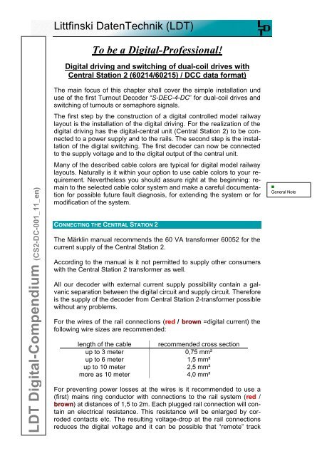
CONNECTING THE CENTRAL STATION 2<br />
The Märklin manual recomm<strong>en</strong>ds the 60 VA transformer 60052 for the<br />
curr<strong>en</strong>t supply of the C<strong>en</strong>tral Station 2.<br />
According to the manual is it not permitted to supply other consumers<br />
with the C<strong>en</strong>tral Station 2 transformer as well.<br />
All our decoder with external curr<strong>en</strong>t supply possibility contain a galvanic<br />
separation betwe<strong>en</strong> the digital circuit and supply circuit. Therefore<br />
is the supply of the decoder from C<strong>en</strong>tral Station 2-transformer possible<br />
without any problems.<br />
For the wires of the rail connections (red / brown =digital curr<strong>en</strong>t) the<br />
following wire sizes are recomm<strong>en</strong>ded:<br />
l<strong>en</strong>gth of the cable<br />
up to 3 meter<br />
up to 6 meter<br />
up to 10 meter<br />
more as 10 meter<br />
recomm<strong>en</strong>ded cross section<br />
0,75 mm²<br />
1,5 mm²<br />
2,5 mm²<br />
4,0 mm²<br />
For prev<strong>en</strong>ting power losses at the wires is it recomm<strong>en</strong>ded to use a<br />
(first) mains ring conductor with connections to the rail system (red /<br />
brown) at distances of 1,5 to 2m. Each plugged rail connection will contain<br />
an electrical resistance. This resistance will be <strong>en</strong>larged by corroded<br />
contacts etc. The resulting voltage-drop at the rail connections<br />
reduces the digital voltage and it can be possible that “remote” track<br />
•<br />
G<strong>en</strong>eral Note
SA-DEC-4 (1) SA-DEC-4 (1) SA-DEC-4 (1) SA-DEC-4 (1)<br />
Ausgang 1 Ausgang 2 Ausgang 3 Ausgang 4<br />
SA-DEC-4 SA-DEC-4 SA-DEC-4 SA-DEC-4<br />
Ausgang 1 Ausgang 2 Ausgang 3 Ausgang 4<br />
SA-DEC-4 (2) SA-DEC-4 (2) SA-DEC-4 (2) SA-DEC-4 (2)<br />
Ausgang 1 Ausgang 2 Ausgang 3 Ausgang 4<br />
LS-DEC-DB 30 LS-DEC-DB 32<br />
Littfinski Dat<strong>en</strong>Technik (<strong>LDT</strong>)<br />
D-25492 Heist/Germany • Kleiner Ring 9 • www.ldt-infoc<strong>en</strong>ter.com<br />
sections will ev<strong>en</strong>tually not get the full digital voltage – disturbances or<br />
inexplicable abnormal behavior can be expected. A suffici<strong>en</strong>t diameter<br />
of the supply-wires will contain a considerable lower resistance and assures<br />
therefore the full supply of the voltage to the rails.<br />
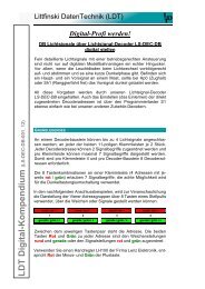
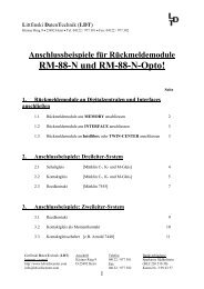
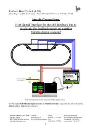
The below picture shows the g<strong>en</strong>eral connection of a c<strong>en</strong>tral unit and<br />
the additional power supply connections at your model railway layout:<br />
Vom Modellbahntrafo 60052<br />
From transformer 60052<br />
rot<br />
red<br />
braun<br />
brown<br />
•<br />
Connection of the<br />
C<strong>en</strong>tral Station 2<br />
(page_970)<br />
keyboard layout memory setup control<br />
digital<br />
01 02 03 04 05 06 07 08<br />
Keine Lok<br />
Keine Lok<br />
c<strong>en</strong>tral station<br />
THE FIRST TURNOUT-DECODER (S-DEC-4-<strong>DC</strong>)<br />
Now to the second step on the way of digital switching at your digital<br />
model railway layout.<br />
The Märklin C<strong>en</strong>tral Station 2 (60214/60215) can uses the <strong>DC</strong>C-data<br />
format for transmittance to the driving of locomotives and for the switching.<br />
For this data format we offer our 4-fold Turnout Decoder “S-DEC-4-<br />
<strong>DC</strong>” within our program.<br />
Also the Turnout-Decoder require a connection to the power supply (14<br />
– 18 V ~) and to the digital voltage. All digital commands to the locdecoder<br />
will be transmitted on this way.<br />
Page 2 / 8<br />
<strong>LDT</strong> <strong>Digital</strong>-<strong>Comp<strong>en</strong>dium</strong> <strong>CS2</strong>-<strong>DC</strong>-<strong>001</strong>_<strong>11</strong>_<strong>en</strong>
J<br />
K<br />
J<br />
K<br />
J<br />
K<br />
Littfinski Dat<strong>en</strong>Technik (<strong>LDT</strong>)<br />
D-25492 Heist/Germany • Kleiner Ring 9 • www.ldt-infoc<strong>en</strong>ter.com<br />
Modellbahntrafo<br />
Transformer<br />
14..18V~<br />
Von Steuereinheit<br />
oder Booster<br />
From command station<br />
or booster<br />
braun<br />
brown<br />
rot<br />
red<br />
~ ~<br />
14 .. 18V<br />
Littfinski Dat<strong>en</strong>Technik (<strong>LDT</strong>) 1 R<br />
G G 2 R<br />
KL2<br />
4fach Weich<strong>en</strong>decoder<br />
Accessory Decoder<br />
S-DEC-4<br />
Rev. 2.1<br />
Multi-<strong>Digital</strong><br />
Littfinski Dat<strong>en</strong>Technik<br />
D-25492 Heist<br />
www.ldt-infoc<strong>en</strong>ter.com<br />
Für 4 Doppelspul<strong>en</strong>antriebe für NMRA <strong>DC</strong>C<br />
<strong>Digital</strong>systeme. Schaltstrom: 1 Ampere pro<br />
Ausgang.<br />
Magnetartikel-Decoder<br />
S-DEC-4-<strong>DC</strong><br />
<strong>Digital</strong>-Profi werd<strong>en</strong>!<br />
KL1<br />
Red<br />
Black<br />
J<br />
K<br />
G S1 red brown<br />
G 3 R 4 R<br />
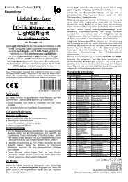
•<br />
Connection of the<br />
Turnout-Decoder<br />
S-DEC-4-<strong>DC</strong><br />
(page_101)<br />
Power supply (black wires at above sample) will be required for the<br />
module itself and for the switching of the coil drives. The decoder module<br />
requires a spacing curr<strong>en</strong>t flow of about 0,1 Ampere. Each output<br />
can cover a maximum switching curr<strong>en</strong>t load of up to 1 Ampere.<br />
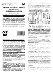
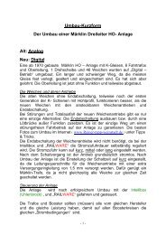
By connecting the supply voltage of 14 – 18 Volt ~ please pay<br />
careful att<strong>en</strong>tion that you use the two inputs of the clamp KL2 which are<br />
marked with “~”. One of the two terminals of the supply voltage shall<br />
never be connected to the ground output “- ” of the 3 poles clamp KL2.<br />
If this happ<strong>en</strong>s the decoder will be destroyed as shown within the following<br />
connection sample.<br />
Modellbahntrafo<br />
Transformer<br />
14..18V~<br />
~ ~<br />
14 .. 18V<br />
KL2<br />
4fach Weich<strong>en</strong>decoder<br />
Accessory Decoder<br />
S-DEC-4<br />
Rev. 2.1<br />
Littfinski Dat<strong>en</strong>Technik (<strong>LDT</strong>) G 1 R G 2 R<br />
Multi-<strong>Digital</strong><br />
Littfinski Dat<strong>en</strong>Technik<br />
D-25492 Heist<br />
www.ldt-infoc<strong>en</strong>ter.com<br />
Für 4 Doppelspul<strong>en</strong>antriebe für NMRA <strong>DC</strong>C<br />
<strong>Digital</strong>systeme. Schaltstrom: 1 Ampere pro<br />
Ausgang.<br />
Magnetartikel-Decoder<br />
S-DEC-4-<strong>DC</strong><br />
<strong>Digital</strong>-Profi werd<strong>en</strong>!<br />
KL1<br />
Red<br />
Black<br />
G 3 R G 4 R<br />
S1 red brown<br />
Modellbahntrafo<br />
Transformer<br />
14..18V~<br />
~ ~<br />
14 .. 18V<br />
Littfinski Dat<strong>en</strong>Technik (<strong>LDT</strong>) 1 R<br />
G G 2 R<br />
KL2<br />
4fach Weich<strong>en</strong>decoder<br />
Accessory Decoder<br />
S-DEC-4<br />
Rev. 2.1<br />
Multi-<strong>Digital</strong><br />
Littfinski Dat<strong>en</strong>Technik<br />
D-25492 Heist<br />
www.ldt-infoc<strong>en</strong>ter.com<br />
Für 4 Doppelspul<strong>en</strong>antriebe für NMRA <strong>DC</strong>C<br />
<strong>Digital</strong>systeme. Schaltstrom: 1 Ampere pro<br />
Ausgang.<br />
Magnetartikel-Decoder<br />
S-DEC-4-<strong>DC</strong><br />
<strong>Digital</strong>-Profi werd<strong>en</strong>!<br />
KL1<br />
Red<br />
Black<br />
G 3 R G 4 R<br />
S1 red brown<br />
•<br />
Correct connection<br />
of the external<br />
supply voltage<br />
(page_508)<br />
The turnouts or signals have to be connected with three cables (blue /<br />
yellow / blue) which can be of a preferable short l<strong>en</strong>gth by a considerable<br />
close distance of the decoder to the respective turnout or signal.<br />
The common conductor of the turnout- or signal-drive (yellow) shall be<br />
connected to the middle contact of the decoder module marked by a<br />
digit. The clamps marked with “G” and “R” are supposed for the coil<br />
drives and are indicating the turnout position to be switched (G for<br />
straight and R for round).<br />
<strong>LDT</strong> <strong>Digital</strong>-<strong>Comp<strong>en</strong>dium</strong> <strong>CS2</strong>-<strong>DC</strong>-<strong>001</strong>_<strong>11</strong>_<strong>en</strong> Page 3 / 8
Littfinski Dat<strong>en</strong>Technik (<strong>LDT</strong>)<br />
D-25492 Heist/Germany • Kleiner Ring 9 • www.ldt-infoc<strong>en</strong>ter.com<br />
•<br />
G<strong>en</strong>eral Note<br />
If it is required to ext<strong>en</strong>d the connection cables of a turnout drive it has<br />
to be tak<strong>en</strong> care of a suffici<strong>en</strong>t diameter of the connection wires. For a<br />
maximum curr<strong>en</strong>t of 1 Ampere at the decoder output is the ordinary<br />
used wiring of 0,14 mm² not suffici<strong>en</strong>t. We recomm<strong>en</strong>d to use wires of<br />
0,5 mm² for a suffici<strong>en</strong>t installation to ext<strong>en</strong>ded turnouts or signals.<br />
It is possible to use the digital curr<strong>en</strong>t for the supply to the decoder<br />
modules. This should be installed on small layouts only because in this<br />
case the exp<strong>en</strong>sive digital curr<strong>en</strong>t will be “wasted” for the curr<strong>en</strong>t supply<br />
to the decoder and for switching the drives.<br />
Von Steuereinheit<br />
oder Booster<br />
From command station<br />
or booster<br />
braun<br />
brown<br />
rot<br />
red<br />
•<br />
<strong>Digital</strong> curr<strong>en</strong>t<br />
supply to the<br />
S-DEC-4-<strong>DC</strong><br />
(page_102)<br />
~ ~<br />
14 .. 18V<br />
Littfinski Dat<strong>en</strong>Technik (<strong>LDT</strong>) 1 R<br />
G G 2 R<br />
KL2<br />
4fach Weich<strong>en</strong>decoder<br />
Accessory Decoder<br />
S-DEC-4<br />
Rev. 2.1<br />
Multi-<strong>Digital</strong><br />
Littfinski Dat<strong>en</strong>Technik<br />
D-25492 Heist<br />
www.ldt-infoc<strong>en</strong>ter.com<br />
Für 4 Doppelspul<strong>en</strong>antriebe für NMRA <strong>DC</strong>C<br />
<strong>Digital</strong>systeme. Schaltstrom: 1 Ampere pro<br />
Ausgang.<br />
Magnetartikel-Decoder<br />
S-DEC-4-<strong>DC</strong><br />
<strong>Digital</strong>-Profi werd<strong>en</strong>!<br />
KL1<br />
Red<br />
Black<br />
J<br />
G S1 red brown<br />
K<br />
G 3 R 4 R<br />
If the available digital curr<strong>en</strong>t (the C<strong>en</strong>tral Station 2 60214 requires<br />
about 3 Ampere and the 60215 about 5 Ampere) will be not suffici<strong>en</strong>t<br />
for the operation of the layout it will be required to use an additional<br />
digital amplifier (= Booster e.g. “DB-2” or “DB-4”). This requires naturally<br />
additional wiring installation and further cost (exp<strong>en</strong>sive digital curr<strong>en</strong>t!).<br />
Page 4 / 8<br />
<strong>LDT</strong> <strong>Digital</strong>-<strong>Comp<strong>en</strong>dium</strong> <strong>CS2</strong>-<strong>DC</strong>-<strong>001</strong>_<strong>11</strong>_<strong>en</strong>
keyboard<br />
layout<br />
SA-DEC-4 (1) SA-DEC-4 (1) SA-DEC-4 (1) SA-DEC-4 (1)<br />
Ausgang 1 Ausgang 2 Ausgang 3 Ausgang 4<br />
SA-DEC-4 SA-DEC-4 SA-DEC-4 SA-DEC-4<br />
Ausgang 1 Ausgang 2 Ausgang 3 Ausgang 4<br />
memory<br />
setup<br />
SA-DEC-4 (2) SA-DEC-4 (2) SA-DEC-4 (2) SA-DEC-4 (2)<br />
Ausgang 1 Ausgang 2 Ausgang 3 Ausgang 4<br />
LS-DEC-DB 30 LS-DEC-DB 32<br />
01 02 03 04 05 06 07 08<br />
Keine Lok<br />
Keine Lok<br />
control<br />
Multi-<strong>Digital</strong><br />
Multi-<strong>Digital</strong><br />
Littfinski Dat<strong>en</strong>Technik (<strong>LDT</strong>)<br />
D-25492 Heist/Germany • Kleiner Ring 9 • www.ldt-infoc<strong>en</strong>ter.com<br />
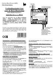
The next sample shows the connection of two of four possible turnouts<br />
and the connection of a further decoder module for an additional group<br />
of four turnouts.<br />
1<br />
2<br />
1 2<br />
Vom Modellbahntrafo 60052<br />
From transformer 60052<br />
rot<br />
red<br />
braun<br />
brown<br />
KL1<br />
Red<br />
J<br />
Black<br />
K<br />
G S1 red brown<br />
KL2<br />
~ ~<br />
14 .. 18V<br />
4fach Weich<strong>en</strong>decoder<br />
Accessory Decoder<br />
S-DEC-4<br />
Rev. 2.1<br />
Littfinski Dat<strong>en</strong>Technik (<strong>LDT</strong>)<br />
G 3 R 4 R<br />
<strong>Digital</strong>-Profi werd<strong>en</strong>!<br />
Magnetartikel-Decoder<br />
S-DEC-4-<strong>DC</strong><br />
Für 4 Doppelspul<strong>en</strong>antriebe für NMRA <strong>DC</strong>C<br />
<strong>Digital</strong>systeme. Schaltstrom: 1 Ampere pro<br />
Ausgang.<br />
Littfinski Dat<strong>en</strong>Technik<br />
D-25492 Heist<br />
www.ldt-infoc<strong>en</strong>ter.com<br />
G<br />
1 R<br />
G<br />
2 R<br />
KL1<br />
Red<br />
J<br />
KL2<br />
Black<br />
K<br />
G S1 red brown<br />
~ ~<br />
14 .. 18V<br />
4fach Weich<strong>en</strong>decoder<br />
Accessory Decoder<br />
S-DEC-4<br />
Rev. 2.1<br />
Littfinski Dat<strong>en</strong>Technik (<strong>LDT</strong>)<br />
G 3 R 4 R<br />
<strong>Digital</strong>-Profi werd<strong>en</strong>!<br />
Magnetartikel-Decoder<br />
S-DEC-4-<strong>DC</strong><br />
Für 4 Doppelspul<strong>en</strong>antriebe für NMRA <strong>DC</strong>C<br />
<strong>Digital</strong>systeme. Schaltstrom: 1 Ampere pro<br />
Ausgang.<br />
Littfinski Dat<strong>en</strong>Technik<br />
D-25492 Heist<br />
www.ldt-infoc<strong>en</strong>ter.com<br />
G<br />
1 R<br />
G<br />
2 R<br />
Vom Modellbahntrafo<br />
From transformer<br />
•<br />
Connecting several<br />
Turnout<br />
Decoder<br />
S-DEC-4-<strong>DC</strong><br />
(page_971)<br />
digital<br />
c<strong>en</strong>tral station<br />
It is recomm<strong>en</strong>ded to install a separate second main ring conductor for<br />
the digital curr<strong>en</strong>t to the turnout- and switch decoder (red / brown) and<br />
a third main ring conductor for the voltage supply (black).<br />
The digital information for the accessory decoders should never be<br />
tak<strong>en</strong> directly from the rails. The driving locomotives can influ<strong>en</strong>ce the<br />
digital signal by producing continually a kind of loose contact signal.<br />
This can result to the problem that the decoder cannot understand the<br />
signal. For this reason will be the loc commands continually repeated.<br />
Especially for the switch commands which will not be transmitted several<br />
times as done by the loc commands is it possible that commands<br />
will be getting lost if the digital information has be<strong>en</strong> tak<strong>en</strong> directly from<br />
the rails.<br />
<strong>LDT</strong> <strong>Digital</strong>-<strong>Comp<strong>en</strong>dium</strong> <strong>CS2</strong>-<strong>DC</strong>-<strong>001</strong>_<strong>11</strong>_<strong>en</strong> Page 5 / 8
Littfinski Dat<strong>en</strong>Technik (<strong>LDT</strong>)<br />
D-25492 Heist/Germany • Kleiner Ring 9 • www.ldt-infoc<strong>en</strong>ter.com<br />
Ringleitung <strong>Digital</strong>strom<br />
Ring conductor digital curr<strong>en</strong>t<br />
rot / K<br />
red / K<br />
braun / J<br />
brown / J<br />
G 3 R 4 R<br />
Black<br />
K<br />
G S1 red brown<br />
KL1<br />
Red<br />
J<br />
G 3 R 4 R<br />
Black<br />
K<br />
G S1 red brown<br />
KL1<br />
Red<br />
J<br />
<strong>Digital</strong>-Profi werd<strong>en</strong>!<br />
Magnetartikel-Decoder<br />
S-DEC-4-<strong>DC</strong><br />
Für 4 Doppelspul<strong>en</strong>antriebe für NMRA <strong>DC</strong>C<br />
<strong>Digital</strong>systeme. Schaltstrom: 1 Ampere pro<br />
Ausgang.<br />
Littfinski Dat<strong>en</strong>Technik<br />
Multi-<strong>Digital</strong><br />
D-25492 Heist<br />
www.ldt-infoc<strong>en</strong>ter.com<br />
•<br />
2. and 3.<br />
Main Ring Conductor<br />
for accessory<br />
Decoders<br />
(page_260)<br />
KL2<br />
~ ~<br />
14 .. 18V<br />
4fach Weich<strong>en</strong>decoder<br />
Accessory Decoder<br />
S-DEC-4<br />
Rev. 2.1<br />
Littfinski Dat<strong>en</strong>Technik (<strong>LDT</strong>)<br />
G 1 R<br />
G 2 R<br />
KL2<br />
~ ~<br />
14 .. 18V<br />
Ringleitung Versorgung<br />
Ring conductor supply<br />
4fach Weich<strong>en</strong>decoder<br />
Accessory Decoder<br />
S-DEC-4<br />
Rev. 2.1<br />
Littfinski Dat<strong>en</strong>Technik (<strong>LDT</strong>)<br />
G 1 R<br />
G 2 R<br />
There are as well some recomm<strong>en</strong>dations for the wire cross-section<br />
dim<strong>en</strong>sion to be used for the two main ring conductor wires. As there<br />
will be a low curr<strong>en</strong>t flow only, the wire dim<strong>en</strong>sion can be a little smaller.<br />
l<strong>en</strong>gth of the cable<br />
up to 10 m<br />
more as 10 m<br />
recomm<strong>en</strong>ded cross section<br />
0,75 mm²<br />
1,0 - 1,5 mm²<br />
At least after completion of the wiring installation you should start the<br />
first test and the placing of suitable a digital address for the turnout (or<br />
signal).<br />
THE FIRST PROGRAMMING<br />
The assignm<strong>en</strong>t of digital addresses has to be carried out individually<br />
for each module. The address is valid for the respective complete group<br />
of four (e.g. 1 - 4, 5 - 8, 9 - 12 etc.). For setting the address (= read-in<br />
address) you have to connect a turnout to the output 1 at the module.<br />
Before you can start programming decoder via the “keyboard” of the<br />
C<strong>en</strong>tral Station 2 you have to deactivate the two drive controller by selecting<br />
the command “No” locomotive.<br />
Following this procedure please start again the C<strong>en</strong>tral Station 2 via<br />
“setup” and “restart”.<br />
The turnout will start switching at a 1,5 second interval after activating<br />
the programming key at the decoder. The decoder module is now in a<br />
learning mode. Now is it required to select and activate a turnout (1 – 4,<br />
5 – 8, etc.) at the keyboard of the c<strong>en</strong>tral unit. The decoder module<br />
takes over the four addresses for the four outputs and confirms the setting<br />
by switching the connected turnout for a short period a little faster.<br />
Page 6 / 8<br />
<strong>LDT</strong> <strong>Digital</strong>-<strong>Comp<strong>en</strong>dium</strong> <strong>CS2</strong>-<strong>DC</strong>-<strong>001</strong>_<strong>11</strong>_<strong>en</strong>
Littfinski Dat<strong>en</strong>Technik (<strong>LDT</strong>)<br />
D-25492 Heist/Germany • Kleiner Ring 9 • www.ldt-infoc<strong>en</strong>ter.com<br />
Depressing again the programming key at the decoder will complete the<br />
setting of addresses. The addresses are now perman<strong>en</strong>tly stored at the<br />
decoder.<br />
Our tip: Carry out the set-up of digital addresses before installing the<br />
decoder module below the layout because the handling of the module<br />
with all connections is much easier at a working b<strong>en</strong>ch. After address<br />
setting please mark the module with the assigned digital addresses<br />
(e.g. label marked with a p<strong>en</strong>cil “5 – 8” for the second group of four addresses).<br />
•<br />
G<strong>en</strong>eral Note<br />
With this procedure the functional test has be<strong>en</strong> already performed and<br />
a later malfunction after installation (e.g. defect module) can be prev<strong>en</strong>ted.<br />
Doing this after final installation of the unit this would be a difficult<br />
time consuming procedure.<br />
SUPPRESSION OF INTERFERENCES<br />
End-off switched coil drives of turnouts can initiate interfer<strong>en</strong>ces and<br />
therefore influ<strong>en</strong>cing the digital system e.g. with unreliable switching of<br />
turnouts. This problem can be solved by slipping 10 ferrite pearls onto<br />
the common connection wire (yellow) of the turnout drives. This has to<br />
be done very close to the coil housing.<br />
•<br />
Technical Tip<br />
Modellbahntrafo<br />
Transformer<br />
14..18V~<br />
Von Steuereinheit<br />
oder Booster<br />
From command station<br />
or booster<br />
braun<br />
brown<br />
rot<br />
red<br />
10 Ferritperl<strong>en</strong> zur<br />
Unterdrückung von<br />
Störung<strong>en</strong> durch<br />
<strong>en</strong>dabgeschaltete<br />
Weich<strong>en</strong>antriebe.<br />
Bestellbezeichnung: FP<br />
10 ferrit perls for<br />
suppression of<br />
interfer<strong>en</strong>ces caused<br />
by <strong>en</strong>d-off switched turnouts.<br />
Order code: FP<br />
~ ~<br />
14 .. 18V<br />
Littfinski Dat<strong>en</strong>Technik (<strong>LDT</strong>)<br />
1 R<br />
G G 2 R<br />
KL2<br />
4fach Weich<strong>en</strong>decoder<br />
Accessory Decoder<br />
S-DEC-4<br />
Rev. 2.1<br />
Multi-<strong>Digital</strong><br />
Littfinski Dat<strong>en</strong>Technik<br />
D-25492 Heist<br />
www.ldt-infoc<strong>en</strong>ter.com<br />
Für 4 Doppelspul<strong>en</strong>antriebe für NMRA <strong>DC</strong>C<br />
<strong>Digital</strong>systeme. Schaltstrom: 1 Ampere pro<br />
Ausgang.<br />
Magnetartikel-Decoder<br />
S-DEC-4-<strong>DC</strong><br />
<strong>Digital</strong>-Profi werd<strong>en</strong>!<br />
KL1<br />
Red<br />
Black<br />
J<br />
G S1 red brown<br />
K<br />
G 3 R 4 R<br />
•<br />
Ferrite Pearls for<br />
the suppression of<br />
interfer<strong>en</strong>ces by<br />
Coil Drives<br />
(page_239)<br />
The ferrite pearls are available by <strong>LDT</strong> under the order code “FP”. The<br />
connections and the operation of the turnouts as well as the programming<br />
the decoder will not be influ<strong>en</strong>ced.<br />
<strong>LDT</strong> <strong>Digital</strong>-<strong>Comp<strong>en</strong>dium</strong> <strong>CS2</strong>-<strong>DC</strong>-<strong>001</strong>_<strong>11</strong>_<strong>en</strong> Page 7 / 8
Littfinski Dat<strong>en</strong>Technik (<strong>LDT</strong>)<br />
D-25492 Heist/Germany • Kleiner Ring 9 • www.ldt-infoc<strong>en</strong>ter.com<br />
FURTHER INFORMATION<br />
•<br />
Internet:<br />
http://www.ldtinfoc<strong>en</strong>ter.com<br />
Additional information about the operation of digital model railway compon<strong>en</strong>ts<br />
and further helpful connection samples are available within the<br />
operation instructions received with every purchased module and device<br />
and at our ext<strong>en</strong>sive Internet page. All m<strong>en</strong>tioned sample connections<br />
can be loaded down as PDF files (e.g. page_970.pdf) and printed<br />
at an A4 format.<br />
Authors: Harry Kellner and Peter Littfinski<br />
Subject to technical changes and errors.<br />
© 06/2012 by <strong>LDT</strong><br />
Page 8 / 8<br />
<strong>LDT</strong> <strong>Digital</strong>-<strong>Comp<strong>en</strong>dium</strong> <strong>CS2</strong>-<strong>DC</strong>-<strong>001</strong>_<strong>11</strong>_<strong>en</strong>