Enrange Flex 6EX-Tandem Radio Control Equipment ... - Magnetek
Enrange Flex 6EX-Tandem Radio Control Equipment ... - Magnetek
Enrange Flex 6EX-Tandem Radio Control Equipment ... - Magnetek

Create successful ePaper yourself
Turn your PDF publications into a flip-book with our unique Google optimized e-Paper software.
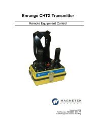
<strong>Flex</strong> <strong>6EX</strong>-<strong>Tandem</strong><br />
<strong>Radio</strong> <strong>Control</strong> <strong>Equipment</strong><br />
Instruction Manual<br />
198-00245-3000 R2<br />
December 2012<br />
© Copyright 2012 <strong>Magnetek</strong> Material Handling
Service Information<br />
Your New <strong>Radio</strong> System<br />
Thank you for your purchase of <strong>Magnetek</strong>’s <strong>Enrange</strong> <strong>Flex</strong> EX radio remote control system. Without a<br />
doubt, our <strong>Flex</strong> EX system is the ultimate solution for providing precise, undeterred, and safe control of<br />
your material.<br />
If your product ever needs modification or service, please contact one of our representatives at the<br />
following locations:<br />
U.S. Service Information:<br />
For questions regarding service or technical information, contact:<br />
1.866.MAG.SERV<br />
(1.866.624.7378)<br />
<strong>Magnetek</strong> Material Handling<br />
N49 W13650 Campbell Drive<br />
Menomonee Falls, WI 53051<br />
Telephone: 1.800.288.8178<br />
Website:<br />
E-mail:<br />
www.magnetekmh.com<br />
info@magnetekmh.com<br />
Fax Numbers:<br />
Main: 1.800.298.3503<br />
Sales: 1.262.783.3510<br />
Service: 1.262.783.3508<br />
Canada Service Information:<br />
4090B Sladeview Crescent<br />
Mississauga, Ontario<br />
L5L 5Y5 Canada<br />
Phone: 1.800.792.7253<br />
Fax: 1.905.828.5707<br />
416.424.7617 (24/7 Service pager)
Table of Contents<br />
1. INTRODUCTION ......................................................................................................... 4<br />
2. RADIO CONTROLLED SAFETY................................................................................. 5<br />
2.1 CRITICAL INSTALLATION CONSIDERATIONS ................................................................................ 6<br />
2.2 GENERAL ........................................................................................................................................... 6<br />
2.3 PERSONS AUTHORIZED TO OPERATE RADIO CONTROLLED CRANES .................................... 6<br />
2.4 SAFETY INFORMATION AND RECOMMENDED TRAINING FOR RADIO CONTROLLED<br />
EQUIPMENT OPERATORS ..................................................................................................................... 6<br />
2.5 TRANSMITTER UNIT ......................................................................................................................... 8<br />
2.6 PRE-OPERATION TEST .................................................................................................................... 8<br />
2.7 BATTERIES ........................................................................................................................................ 8<br />
2.8 BATTERY HANDLING ........................................................................................................................ 9<br />
2.9 BATTERY CHARGING ....................................................................................................................... 9<br />
2.10 BATTERY DISPOSAL ....................................................................................................................... 9<br />
2.11 SPECIFIC SYSTEM WARNINGS ................................................................................................... 10<br />
3. GENERAL SYSTEM INFORMATION ........................................................................ 11<br />
3.1 SYSTEM SETUP .............................................................................................................................. 11<br />
3.2 TRANSMITTER HANDSET .............................................................................................................. 12<br />
3.2.1 External Illustration (Standard Push Button Configuration) ....................................................... 12<br />
3.2.2 Internal Illustration ..................................................................................................................... 13<br />
3.3 RECEIVER UNIT .............................................................................................................................. 14<br />
3.3.1 External Illustration .................................................................................................................... 14<br />
3.3.2 Internal Illustration ..................................................................................................................... 15<br />
4. FUNCTION SETTINGS ............................................................................................. 16<br />
4.1 TRANSMITTER HANDSET .............................................................................................................. 16<br />
4.1.1 System Channel Settings .......................................................................................................... 16<br />
4.1.2 Channel Change via Push Buttons ........................................................................................... 17<br />
4.1.3 Optional 4-Digit Security Code .................................................................................................. 18<br />
4.1.4 I-CHIP ........................................................................................................................................ 19<br />
4.2 RECEIVER UNIT .............................................................................................................................. 20<br />
4.2.1 System Channel Settings .......................................................................................................... 20<br />
4.2.2 Output Relay Configurations ..................................................................................................... 21<br />
4.2.3 Receiver Auto-Scanning Settings .............................................................................................. 24<br />
4.2.4 Dip-Switch Settings ................................................................................................................... 25<br />
4.2.5 Jumper Settings ........................................................................................................................ 27<br />
4.2.6 I-CHIP Programming Port ......................................................................................................... 28<br />
4.2.7 Fuse Ratings ............................................................................................................................. 28<br />
5. SYSTEM CHANNELS TABLE ................................................................................... 29<br />
6. RECEIVER INSTALLATION ...................................................................................... 30<br />
6.1 OUTPUT RELAY CONTACT DIAGRAM ........................................................................................... 30<br />
6.2 PRE-INSTALLATION PRECAUTIONS ............................................................................................. 30<br />
6.3 STEP-BY-STEP INSTALLATION ...................................................................................................... 31<br />
6.4 SYSTEM TESTING .......................................................................................................................... 32<br />
7. OPERATING PROCEDURE ...................................................................................... 33<br />
7.1 TRANSMITTER OPERATION .......................................................................................................... 33<br />
7.1.1 General Operating Procedure ................................................................................................... 33<br />
7.1.2 <strong>Tandem</strong> Select Operating Procedure ........................................................................................ 34<br />
7.1.3 Automatic Channel Scanning Operating Procedure ................................................................. 36<br />
7.1.4 Changing Transmitter Batteries ................................................................................................. 37<br />
7.2 STATUS LIGHT INDICATORS & WARNINGS ................................................................................. 38<br />
7.2.1 Transmitter STATUS Light Indication ........................................................................................ 38<br />
7.2.2 Receiver STATUS Light Indication ............................................................................................ 39<br />
7.2.3 Receiver SQ Light Indication ..................................................................................................... 39<br />
7.2.4 Receiver POWER Light Indication ............................................................................................ 39<br />
7.2.5 Receiver COM Light Indication .................................................................................................. 39<br />
<strong>Flex</strong> <strong>6EX</strong>-<strong>Tandem</strong> Instruction Manual<br />
December 2012<br />
Page 1 of 41
7.3 TROUBLESHOOTING TIPS ............................................................................................................. 40<br />
8. SYSTEM SPECIFICATIONS ..................................................................................... 41<br />
<strong>Flex</strong> <strong>6EX</strong>-<strong>Tandem</strong> Instruction Manual<br />
December 2012<br />
Page 2 of 41
PRODUCT MANUAL SAFETY INFORMATION<br />
<strong>Magnetek</strong>, Inc. (<strong>Magnetek</strong>) offers a broad range of radio remote control products, control products<br />
and adjustable frequency drives, and industrial braking systems for material handling applications. This<br />
manual has been prepared by <strong>Magnetek</strong> to provide information and recommendations for the installation,<br />
use, operation and service of <strong>Magnetek</strong>’s material handling products and systems (<strong>Magnetek</strong> Products).<br />
Anyone who uses, operates, maintains, services, installs or owns <strong>Magnetek</strong> Products should know,<br />
understand and follow the instructions and safety recommendations in this manual for <strong>Magnetek</strong><br />
Products.<br />
The recommendations in this manual do not take precedence over any of the following<br />
requirements relating to cranes, hoists, lifting devices or other material handling equipment which use or<br />
include <strong>Magnetek</strong> Products:<br />
<br />
<br />
<br />
<br />
<br />
Instructions, manuals, and safety warnings of the manufacturers of the equipment where the<br />
radio system is used,<br />
Plant safety rules and procedures of the employers and the owners of facilities where the<br />
<strong>Magnetek</strong> Products are being used,<br />
Regulations issued by the Occupational Health and Safety Administration (OSHA),<br />
Applicable local, state or federal codes, ordinances, standards and requirements, or<br />
Safety standards and practices for the industries in which <strong>Magnetek</strong> Products are used.<br />
This manual does not include or address the specific instructions and safety warnings of these<br />
manufacturers or any of the other requirements listed above. It is the responsibility of the owners, users<br />
and operators of the <strong>Magnetek</strong> Products to know, understand and follow all of these requirements. It is<br />
the responsibility of the employer to make its employees aware of all of the above listed requirements and<br />
to make certain that all operators are properly trained. No one should use <strong>Magnetek</strong> Products prior to<br />
becoming familiar with and being trained in these requirements and the instructions and safety<br />
recommendations in this manual.<br />
WARRANTY INFORMATION<br />
For information on <strong>Magnetek</strong>’s product warranties by product type, please visit www.magnetekmh.com.<br />
<strong>Flex</strong> <strong>6EX</strong>-<strong>Tandem</strong> Instruction Manual<br />
December 2012<br />
Page 3 of 41
1. INTRODUCTION<br />
The <strong>Flex</strong> radio remote control systems are designed for control of industrial equipment and machinery such<br />
as overhead traveling cranes, jib cranes, gantry cranes, tower cranes, electric hoists, winches, monorails,<br />
conveyor belts, mining equipment and other material handling equipment where wireless control is<br />
preferred.<br />
Each <strong>Flex</strong> system consists of a transmitter handset and receiver unit. Other standard-equipped accessories<br />
include transmitter waist belt, spare transmitter power key, clear vinyl pouch, “AA” alkaline batteries,<br />
compass direction decal sheet and user’s manual.<br />
List of notable features include:<br />
* 62 user-programmable channels – Advanced synthesized RF controls with 62 built-in channels;<br />
there are no more fixed channels and fragile quartz crystals to break.<br />
* Automatic channel scanning receiver – No more hassle of climbing up the crane to change<br />
receiver channels.<br />
* Over one million unique ID codes (20bit) – Each and every <strong>Flex</strong> system has its own unique ID<br />
codes and serial number; never repeats.<br />
* Advanced controls – The <strong>Flex</strong> system utilizes advanced microprocessor controls with 32bit CRC<br />
and Hamming Code, which provide ultra fast, safe, precise, and error-free encoding and decoding.<br />
* Unique I-CHIP design – The I-CHIP functions in a way that is very similar to SIM cards used on<br />
mobile phones, with the ability to transfer system information and settings from one transmitter to<br />
another without the hassle of resetting the spares.<br />
* Reliable push buttons – The in-house designed push buttons with gold-plated contacts are rated for<br />
more than one million press cycles.<br />
* Low power consumption – Requires only two “AA” Alkaline batteries for more than 100 hours of<br />
operating time between replacements.<br />
* Ultra-durable nylon and fiberglass composite enclosures – Highly resistant to breakage and<br />
deformation even in the most abusive environments.<br />
* Full compliance – All systems are fully compliant with the FCC Part-15 Rules, European Directives<br />
(Safety, EMC, R&TTE, Machinery), and Industry Canada Specifications (IC).<br />
<strong>Flex</strong> <strong>6EX</strong>-<strong>Tandem</strong> Instruction Manual<br />
December 2012<br />
Page 4 of 41
2. RADIO CONTROLLED SAFETY<br />
WARNINGS and CAUTIONS<br />
Throughout this document WARNING and CAUTION statements have been deliberately placed to highlight items<br />
critical to the protection of personnel and equipment.<br />
WARNING – A warning highlights an essential operating or maintenance procedure, practice, etc. which if<br />
not strictly observed, could result in injury or death of personnel, or long term physical hazards. Warnings<br />
are highlighted as shown below:<br />
WARNING<br />
CAUTION – A caution highlights an essential operating or maintenance procedure, practice, etc. which if not<br />
strictly observed, could result in damage to, or destruction of equipment, or loss of functional effectiveness.<br />
Cautions are highlighted as shown below:<br />
CAUTION<br />
WARNINGS and CAUTIONS SHOULD NEVER BE DISREGARDED.<br />
The safety rules in this section are not intended to replace any rules or regulations of any applicable local, state, or<br />
federal governing organizations. Always follow your local lockout and tagout procedure when maintaining any radio<br />
equipment. The following information is intended to be used in conjunction with other rules or regulations already in<br />
existence. It is important to read all of the safety information contained in this section before installing or operating the<br />
<strong>Radio</strong> <strong>Control</strong> System.<br />
<strong>Flex</strong> <strong>6EX</strong>-<strong>Tandem</strong> Instruction Manual<br />
December 2012<br />
Page 5 of 41
2.1 CRITICAL INSTALLATION CONSIDERATIONS<br />
WARNING<br />
PRIOR TO INSTALLATION AND OPERATION OF THIS EQUIPMENT, READ AND DEVELOP AN UNDERSTANDING<br />
OF THE CONTENTS OF THIS MANUAL AND THE OPERATION MANUAL OF THE EQUIPMENT OR DEVICE TO<br />
WHICH THIS EQUIPMENT WILL BE INTERFACED. FAILURE TO FOLLOW THIS WARNING COULD RESULT IN<br />
SERIOUS INJURY OR DEATH AND DAMAGE TO EQUIPMENT.<br />
ALL EQUIPMENT MUST HAVE A MAINLINE CONTACTOR INSTALLED AND ALL TRACKED CRANES, HOISTS,<br />
LIFTING DEVICES AND SIMILAR EQUIPMENT MUST HAVE A BRAKE INSTALLED. FAILURE TO FOLLOW THIS<br />
WARNING COULD RESULT IN SERIOUS INJURY OR DEATH AND DAMAGE TO EQUIPMENT.<br />
AN AUDIBLE AND/OR VISUAL WARNING MEANS MUST BE PROVIDED ON ALL REMOTE CONTROLLED<br />
EQUIPMENT AS REQUIRED BY CODE, REGULATION, OR INDUSTRY STANDARD. THESE AUDIBLE AND/OR<br />
VISUAL WARNING DEVICES MUST MEET ALL GOVERNMENTAL REQUIREMENTS. FAILURE TO FOLLOW THIS<br />
WARNING COULD RESULT IN SERIOUS INJURY OR DEATH AND DAMAGE TO EQUIPMENT.<br />
FOLLOW YOUR LOCAL LOCKOUT TAGOUT PROCEDURE BEFORE MAINTAINING ANY REMOTE<br />
CONTROLLED EQUIPMENT. ALWAYS REMOVE ALL ELECTRICAL POWER FROM THE CRANE, HOIST, LIFTING<br />
DEVICE OR SIMILAR EQUIPMENT BEFORE ATTEMPTING ANY INSTALLATION PROCEDURES. DE-ENERGIZE<br />
AND TAGOUT ALL SOURCES OF ELECTRICAL POWER BEFORE TOUCH-TESTING ANY EQUIPMENT. FAILURE<br />
TO FOLLOW THIS WARNING COULD RESULT IN SERIOUS INJURY OR DEATH AND DAMAGE TO EQUIPMENT.<br />
THE DIRECT OUTPUTS OF THIS PRODUCT ARE NOT DESIGNED TO INTERFACE DIRECTLY TO TWO STATE<br />
SAFETY CRITICAL MAINTAINED FUNCTIONS, I.E., MAGNETS, VACUUM LIFTS, PUMPS, EMERGENCY<br />
EQUIPMENT, ETC. A MECHANICALLY LOCKING INTERMEDIATE RELAY SYSTEM WITH SEPARATE POWER<br />
CONSIDERATIONS MUST BE PROVIDED. FAILURE TO FOLLOW THIS WARNING COULD RESULT IN SERIOUS<br />
INJURY OR DEATH OR DAMAGE TO EQUIPMENT.<br />
2.2 GENERAL<br />
<strong>Radio</strong> controlled material handling equipment operates in several directions. Cranes, hoists, lifting devices and other<br />
material handling equipment can be large, and operate at high speeds. Quite frequently, the equipment is operated<br />
in areas where people are working in close proximity to the material handling equipment. The operator must<br />
exercise extreme caution at all times. Workers must constantly be alert to avoid accidents. The following<br />
recommendations have been included to indicate how careful and thoughtful actions may prevent injuries, damage to<br />
equipment, or even save a life.<br />
2.3 PERSONS AUTHORIZED TO OPERATE RADIO CONTROLLED<br />
CRANES<br />
Only properly trained persons designated by management should be permitted to operate radio controlled equipment.<br />
<strong>Radio</strong> controlled cranes, hoists, lifting devices and other material handling equipment should not be operated by any<br />
person who cannot read or understand signs, notices and operating instructions that pertain to the equipment.<br />
<strong>Radio</strong> controlled equipment should not be operated by any person with insufficient eyesight or hearing or by any<br />
person who may be suffering from a disorder or illness, is taking any medication that may cause loss of equipment<br />
control, or is under the influence of alcohol or drugs.<br />
2.4 SAFETY INFORMATION AND RECOMMENDED TRAINING FOR<br />
RADIO CONTROLLED EQUIPMENT OPERATORS<br />
Anyone being trained to operate radio controlled equipment should possess as a minimum the following knowledge<br />
<strong>Flex</strong> <strong>6EX</strong>-<strong>Tandem</strong> Instruction Manual<br />
December 2012<br />
Page 6 of 41
and skills before using the radio controlled equipment.<br />
The operator should:<br />
have knowledge of hazards pertaining to equipment operation<br />
have knowledge of safety rules for radio controlled equipment<br />
have the ability to judge distance of moving objects<br />
know how to properly test prior to operation<br />
be trained in the safe operation of the radio transmitter as it pertains to the crane, hoist, lifting device or other<br />
material handling equipment being operated<br />
have knowledge of the use of equipment warning lights and alarms<br />
have knowledge of the proper storage space for a radio control transmitter when not in use<br />
be trained in transferring a radio control transmitter to another person<br />
be trained how and when to report unsafe or unusual operating conditions<br />
test the transmitter emergency stop and all warning devices prior to operation; testing should be done on each<br />
shift, without a load<br />
be thoroughly trained and knowledgeable in proper and safe operation of the crane, hoist, lifting device, or<br />
other material handling equipment that utilizes the radio control<br />
know how to keep the operator and other people clear of lifted loads and to avoid “pinch” points<br />
continuously watch and monitor status of lifted loads<br />
know and follow cable and hook inspection procedures<br />
know and follow the local lockout and tagout procedures when servicing radio controlled equipment<br />
know and follow all applicable operating and maintenance manuals, safety procedures, regulatory<br />
requirements, and industry standards and codes<br />
The operator shall not:<br />
<br />
<br />
<br />
<br />
<br />
<br />
<br />
<br />
<br />
<br />
lift or move more than the rated load<br />
operate the material handling equipment if the direction of travel or function engaged does not agree with<br />
what is indicated on the controller<br />
use the crane, hoist or lifting device to lift, support or transport people<br />
lift or carry any loads over people<br />
operate the crane, hoist or lifting device unless all persons, including the operator, are and remain clear of<br />
the supported load and any potential pinch points<br />
operate a crane, hoist or lifting device when the device is not centered over the load<br />
operate a crane, hoist or lifting device if the chain or wire rope is not seated properly in the sprockets, drum<br />
or sheave<br />
operate any damaged or malfunctioning crane, hoist, lifting device or other material handling equipment<br />
change any settings or controls without authorization and proper training<br />
remove or obscure any warning or safety labels or tags<br />
<strong>Flex</strong> <strong>6EX</strong>-<strong>Tandem</strong> Instruction Manual<br />
December 2012<br />
Page 7 of 41
leave any load unattended while lifted<br />
leave power on the radio controlled equipment when the equipment is not in operation<br />
operate any material handling equipment using a damaged controller because the unit may be unsafe<br />
operate manual motions with other than manual power<br />
operate radio controlled equipment when low battery indicator is on<br />
WARNING<br />
THE OPERATOR SHOULD NOT ATTEMPT TO REPAIR ANY RADIO CONTROLLER. IF ANY PRODUCT<br />
PERFORMANCE OR SAFETY CONCERNS ARE OBSERVED, THE EQUIPMENT SHOULD IMMEDIATELY BE<br />
TAKEN OUT OF SERVICE AND BE REPORTED TO THE SUPERVISOR. DAMAGED AND INOPERABLE RADIO<br />
CONTROLLER EQUIPMENT SHOULD BE RETURNED TO MAGNETEK FOR EVALUATION AND REPAIR.<br />
FAILURE TO FOLLOW THIS WARNING COULD RESULT IN SERIOUS INJURY OR DEATH AND DAMAGE TO<br />
EQUIPMENT.<br />
2.5 TRANSMITTER UNIT<br />
Transmitter switches should never be mechanically blocked ON or OFF. When not in use, the operator should turn<br />
the transmitter OFF. A secure storage space should be provided for the transmitter unit, and the transmitter unit<br />
should always be placed there when not in use. This precaution will help prevent unauthorized people from operating<br />
the material handling equipment.<br />
Spare transmitters should be stored in a secure storage space and only removed from the storage space after the<br />
current transmitter in use has been turned OFF, taken out of the service area and secured.<br />
2.6 PRE-OPERATION TEST<br />
At the start of each work shift, or when a new operator takes control of the crane, operators should do, as a<br />
minimum, the following steps before making lifts with any crane or hoist:<br />
Test all warning devices.<br />
Test all direction and speed controls.<br />
Test the transmitter emergency stop.<br />
2.7 BATTERIES<br />
WARNING<br />
KNOW AND FOLLOW PROPER BATTERY HANDLING, CHARGING AND DISPOSAL PROCEDURES. IMPROPER<br />
BATTERY PROCEDURES CAN CAUSE BATTERIES TO EXPLODE OR DO OTHER SERIOUS DAMAGE.<br />
FAILURE TO FOLLOW THIS WARNING COULD RESULT IN SERIOUS INJURY OR DEATH AND DAMAGE TO<br />
EQUIPMENT.<br />
<strong>Flex</strong> <strong>6EX</strong>-<strong>Tandem</strong> Instruction Manual<br />
December 2012<br />
Page 8 of 41
2.8 BATTERY HANDLING<br />
Use only batteries approved by <strong>Magnetek</strong> for the specific product.<br />
Do not dispose of a battery pack in fire; it may explode.<br />
Do not attempt to open the battery pack.<br />
Do not short circuit the battery.<br />
For intrinsically safe environments only use specified <strong>Magnetek</strong> intrinsically safe batteries.<br />
Keep the battery pack environment cool during charging operation and storage (i.e., not in direct sunlight or close to a<br />
heating source).<br />
2.9 BATTERY CHARGING<br />
For those transmitters equipped with battery chargers, please familiarize all users with the instructions of the charger<br />
before attempting to use.<br />
Do not attempt to charge non-rechargeable battery packs.<br />
Avoid charging partially discharged rechargeable batteries to help prolong battery cycle life.<br />
Avoid charging the battery pack for more than 24 hours at a time.<br />
Do not charge batteries in a hazardous environment.<br />
Do not short the charger.<br />
Do not attempt to charge a damaged battery.<br />
Use only <strong>Magnetek</strong> approved chargers for the appropriate battery pack.<br />
Do not attempt to use a battery that is leaking, swollen or corroded.<br />
Charger units are not intended for outdoor use. Use only indoors.<br />
2.10 BATTERY DISPOSAL<br />
Before disposing of batteries consult local and governmental regulatory requirements for proper disposal procedure.<br />
<strong>Flex</strong> <strong>6EX</strong>-<strong>Tandem</strong> Instruction Manual<br />
December 2012<br />
Page 9 of 41
2.11 SPECIFIC SYSTEM WARNINGS<br />
Below are some specific operating safety tips that should be strictly followed when operating a <strong>Flex</strong> <strong>6EX</strong>-<br />
T System:<br />
1. Check the Status LED on the transmitter for any signs of low battery power (refer to page 38).<br />
2. Check the Status LED on the transmitter for any signs of irregularities (refer to page 38).<br />
3. Make sure the system is not set to the same channel as any other <strong>Flex</strong> systems in use within a<br />
distance of 300 meters (900 feet).<br />
4. Never operate a crane or equipment with two transmitter handsets at the same time.<br />
<strong>Flex</strong> <strong>6EX</strong>-<strong>Tandem</strong> Instruction Manual<br />
December 2012<br />
Page 10 of 41
3. GENERAL SYSTEM INFORMATION<br />
3.1 SYSTEM SETUP<br />
The <strong>Flex</strong> <strong>6EX</strong>-T system consists of two dedicated <strong>Flex</strong> 8EX-T transmitters (bottom four buttons are<br />
plugged), two tandem transmitters (a rotary switch is at the lower left, with the remaining three bottom<br />
buttons plugged), and two RXC-22 compact receiver units. In order to properly set up the <strong>Flex</strong> <strong>6EX</strong>-T<br />
system, the following settings must be completed:<br />
1.) Set Transmitter A, and both Receiver A and B to the same channel.<br />
2.) Set both receivers to 3-Channel scanning mode.<br />
3.) Set Transmitter B two channels higher than Transmitter A.<br />
4.) Set <strong>Tandem</strong> Transmitters to one channel higher than Transmitter A.<br />
5.) Set Transmitter A to type 01, Transmitter B to type 02, and <strong>Tandem</strong> Transmitters to type 01.<br />
6.) Set Receiver A to type 01 and Receiver B to type 02.<br />
<strong>Flex</strong> <strong>6EX</strong>-<strong>Tandem</strong> Instruction Manual<br />
December 2012<br />
Page 11 of 41
3.2 TRANSMITTER HANDSET<br />
3.2.1 External Illustration (Standard Push Button Configuration)<br />
(Fig. 01) (Fig. 02)<br />
1. Emergency Stop Button 9. Hole Plug<br />
2. Removable Power Key Switch 10. Hole Plug<br />
3. Push Button #2 11. Strap Ring<br />
4. Push Button #4 12. System Information<br />
5. Hole Plug 13. System Channel<br />
6. Select A, B, A+B Rotary Switch 14. Crane Number<br />
7. Push Button #1 15. Battery Cover<br />
8. Push Button #3 16. FCC Information<br />
NOTE: The Rotary Switch (Item #6) is only used on the <strong>Tandem</strong> Transmitters. Dedicated<br />
Transmitters have a hole plug in this position.<br />
<strong>Flex</strong> <strong>6EX</strong>-<strong>Tandem</strong> Instruction Manual<br />
December 2012<br />
Page 12 of 41
3.2.2 Internal Illustration<br />
(Fig. 03) (Fig. 04)<br />
1. Encoder Board 6. I-CHIP<br />
2. Aerial Antenna 7. Function Dip-Switch<br />
3. Transmitting Module 8. Channel Dip-Switch<br />
4. Status LED Display 9. Battery Contact Mechanism<br />
5. Function LED Displays<br />
<strong>Flex</strong> <strong>6EX</strong>-<strong>Tandem</strong> Instruction Manual<br />
December 2012<br />
Page 13 of 41
3.3 RECEIVER UNIT<br />
3.3.1 External Illustration<br />
1<br />
2<br />
3<br />
4<br />
5<br />
6<br />
7<br />
(Fig. 05)<br />
1. External Antenna Jack (optional) 5. COM LED Display<br />
2. Power LED Display 6. Output Contact Diagram<br />
3. Status LED Display 7. Cord Grip<br />
4. SQ LED Display<br />
<strong>Flex</strong> <strong>6EX</strong>-<strong>Tandem</strong> Instruction Manual<br />
December 2012<br />
Page 14 of 41
3.3.2 Internal Illustration<br />
1<br />
I-CHIP PORT<br />
2<br />
JP7<br />
JP6<br />
JP5<br />
JP4<br />
JP3<br />
JP2<br />
JP1<br />
SYSTEM FUNCTIONS<br />
TEST<br />
3<br />
4<br />
(Fig. 06)<br />
1. Receiving Module 3. AC Line Filter + Relay Board<br />
2. Decoder + Relay Board 4. Power Transformer<br />
<strong>Flex</strong> <strong>6EX</strong>-<strong>Tandem</strong> Instruction Manual<br />
December 2012<br />
Page 15 of 41
4. FUNCTION SETTINGS<br />
4.1 TRANSMITTER HANDSET<br />
4.1.1 System Channel Settings<br />
CHANNEL<br />
1 234<br />
567<br />
8<br />
(Fig. 07)<br />
Set the transmitter channel by adjusting the channel dip-switch located on the backside of the<br />
transmitter encoder board (refer to Fig. 07 above). Only the first six (6) positions are used for<br />
channel programming (refer to Fig. 08 below). The system channels table located on page 29<br />
illustrates which dip-switch setting corresponds to which channel. Once the transmitter channel<br />
is altered, make sure to change the receiver channel as well. The channel on both the<br />
transmitter and receiver must be identical in order for the system to work. To change the<br />
receiver channel please refer to page 20.<br />
Example: Top slot → “1”<br />
1 234<br />
567<br />
8<br />
Bottom slot → “0”<br />
(Fig. 08)<br />
The above dip-switch setting “1 0 0 1 0 0” corresponds to “channel 36” in the system channels<br />
table on page 29.<br />
<strong>Flex</strong> <strong>6EX</strong>-<strong>Tandem</strong> Instruction Manual<br />
December 2012<br />
Page 16 of 41
4.1.2 Channel Change via Push Buttons<br />
Other than the CHANNEL dip-switch on the encoder board, the transmitter channel can also<br />
be changed directly on the push buttons. Please refer to the instructions below on how to<br />
change the transmitter channel via push buttons.<br />
a. Press and hold PB1, PB2 and PB3 and rotate the power key to START position at the<br />
same time. A series of green and red blinks will appear on the Status LED showing the<br />
current channel setting. A green blink represents the tens (+10) and a red blink<br />
represents the units (+1).<br />
Examples: 2 green blinks followed by 5 red blinks represents channel 25.<br />
6 red blinks represents channel 06.<br />
+<br />
b. Select a new channel by pressing PB1 and PB2 on the transmitter. Press PB1 to<br />
increment the units (+1) and PB2 to increment the tens (+10).<br />
Examples: Pressing PB2 two times and then PB1 four times will give you channel 24.<br />
Pressing PB1 nine times with give you channel 09.<br />
c. When finished, the newly selected channel will appear on the Status LED via a series of<br />
green and red blinks again.<br />
d. Exit the channel programming by turning off the transmitter power.<br />
e. Make sure the receiver channel is set identical to the transmitter. Please refer to page 20<br />
and page 24 on how to change the receiver channel.<br />
f. Please note that when the CHANNEL dip-switch inside the transmitter is changed, the<br />
priority will revert back to the new channel set on the CHANNEL dip-switch.<br />
g. Please note that when channel is set beyond channel 62 via PB1 and PB2 (i.e. channel<br />
63, 68, 88, etc…), the system will recognize it as channel 62.<br />
<strong>Flex</strong> <strong>6EX</strong>-<strong>Tandem</strong> Instruction Manual<br />
December 2012<br />
Page 17 of 41
4.1.3 Optional 4-Digit Security Code<br />
The 4-digit Security Code is an optional feature that can be programmed into the transmitter to<br />
allow operation only to those who know the code. If this feature is desired, set up as follows:<br />
Prior to rotating the transmitter power key-switch to START position to begin operation, you<br />
first enter a 4-digit security code in order to proceed further. When this 4-digit security code is<br />
entered correctly, a green light will appear on the Status LED. Please refer to the instructions<br />
below on how to program the 4-digit security code.<br />
a. Release E-Stop, then press and hold PB1, PB2, PB3 and PB4 (all at once), and then<br />
rotate the power key to START position.<br />
+<br />
b. A constant orange light will appear on the Status LED telling you that you are in the<br />
security code programming mode.<br />
c. For newly purchased systems with the security code function deactivated (default<br />
setting), press PB1 four times (1111) to activate the security code function. At this time<br />
the Status LED on the transmitter will blink orange slowly, telling you that the 4 digits<br />
entered is correct. Then select your own 4-digit security code by pressing PB1, PB2, PB3<br />
or PB4 on the transmitter (four presses randomly). At this time, fast orange blinks are<br />
displayed on the Status LED, telling you to reconfirm the 4-digit security code you have<br />
just entered. A green light will appear once you have re-entered the same 4-digit security<br />
code again (programming completed). If any mistake is made during this process, or if a<br />
red light is shown on the Status LED after you have re-entered the security code<br />
(incorrect input), or even if you believe you have entered the correct code but the<br />
transmitter fails to work properly, then you must reset the transmitter power (by powercycling<br />
the transmitter*) and then repeat steps a, b and c again.<br />
*NOTE: To power-cycle the transmitter, you must first remove, then reinstall the batteries.<br />
Simply turning the power switch off and then back on will NOT properly clear the memory.<br />
This process must be used for any errors regarding proper transmitter operation (not just<br />
for security code settings).<br />
Steps: Press and hold PB1~PB4 and rotate power key to START position → constant<br />
orange → press PB1 four times (for new systems) or 4-digit security code → slow orange<br />
blinks → enter the new 4-digit security code → fast orange blinks → re-enter the same 4-<br />
digit security code again → green light.<br />
d. If you wish to cancel the security code function, then repeat steps a, b, and c above and<br />
press PB1 four times as your new security code (security code function disabled).<br />
e. If you do not remember the 4-digit security code, then you must contact your dealer or<br />
distributor for further assistance.<br />
<strong>Flex</strong> <strong>6EX</strong>-<strong>Tandem</strong> Instruction Manual<br />
December 2012<br />
Page 18 of 41
4.1.4 I-CHIP<br />
The I-CHIP functions in a way that is very similar to a SIM card inside a mobile phone, which<br />
stores system information such as your telephone number, account number, phone book and<br />
other settings. The I-CHIP works exactly the same way, as it stores information such as system<br />
serial number/ID codes, channel configurations and push button configurations.<br />
When replacing a transmitter handset, just take the I-CHIP out of the old transmitter and<br />
install it into the new one (refer to Fig. 09 below). For a complete information transfer, make<br />
sure both the Channel and Function dip-switches are set to all “1”. If both dip-switches are<br />
set to all “1”, then the transmitter will operate according to the push button configurations<br />
and channel stored inside the I-CHIP. If both the Channel and the Function dip-switches are<br />
set to values other than all “1”, then the transmitter will operate according to the channel and<br />
push button configurations set on these two dip-switches, not the ones stored inside the I-<br />
CHIP. Every time the settings on these two dip-switches are changed, the new settings will<br />
be stored into the I-CHIP automatically. In this case the previous channel and push button<br />
configurations stored inside the I-CHIP will be erased and be replaced by the new settings.<br />
For safety purposes, the system serial number/ID code stored inside the I-CHIP cannot be<br />
changed directly on the transmitter encoder board. Only channels and push button<br />
configurations can be changed directly on the encoder board via Channel and Function dipswitches.<br />
There are only two ways that you can change transmitter serial number/ID codes: 1)<br />
via the I-CHIP programming port located on the decoder module inside the receiver unit<br />
(please refer to page 28 on how to program the I-CHIP [serial number/ID code] via receiver<br />
unit) or 2) via an external I-CHIP programmer or duplicator unit available from the factory.<br />
Please ask your local dealer for assistance if your system requires serial number/ID code<br />
adjustments.<br />
(Fig. 09)<br />
<strong>Flex</strong> <strong>6EX</strong>-<strong>Tandem</strong> Instruction Manual<br />
December 2012<br />
Page 19 of 41
4.2 RECEIVER UNIT<br />
4.2.1 System Channel Settings<br />
EXT<br />
INT<br />
4 7<br />
1 2 3 5 6 8<br />
(Fig. 10)<br />
Even though the <strong>Flex</strong> system is equipped with an automatic channel scanning receiver, the<br />
user can also set the receiver channel manually. Please refer to page 24 on how the automatic<br />
channel scanning receiver works.<br />
Set the receiver channel by adjusting the channel dip-switch located on the receiver module<br />
(refer to Fig. 10 above); only the first six (6) positions are used for channel programming (refer<br />
to Fig. 11 below). The system channels table located on page 29 illustrates which dip-switch<br />
setting corresponds to which channel. Once the receiver channel is altered make sure to<br />
change the transmitter channel as well. The channel on both the transmitter and the receiver<br />
must be identical in order for system to work. To change the transmitter channel please refer to<br />
page 16.<br />
Example: Top slot → “1”<br />
1 234<br />
567<br />
8<br />
Bottom slot → “0”<br />
(Fig. 11)<br />
The above dip-switch setting “1 0 0 1 0 0” corresponds to “channel 36” in the system channels<br />
table on page 29.<br />
<strong>Flex</strong> <strong>6EX</strong>-<strong>Tandem</strong> Instruction Manual<br />
December 2012<br />
Page 20 of 41
4.2.2 Output Relay Configurations<br />
4.2.2.1 Output Relay Types<br />
Three (3) output relays per motion – shared 2 nd speed output relay<br />
Output relays with Forward 1 st speed (F1), Reverse 1 st speed (R1) and<br />
Forward/Reverse 2 nd speed (F/R2). Forward and Reverse 2 nd speed (F/R2) share<br />
the same output relay.<br />
F1 R1 F/R2<br />
Four (4) output relays per motion – separate 1 st and 2 nd speed output relays<br />
Output relays with Forward 1 st speed (F1), Reverse 1 st speed (R1), Forward 2 nd<br />
speed (F2) and Reverse 2 nd speed (R2). Forward and Reverse 2 nd speed with<br />
separate output relays.<br />
F1<br />
R1<br />
F2<br />
R2<br />
4.2.2.2 Output Relay Actions at 2 nd Speed<br />
3-output relays configuration with Closed/Closed contact at 2 nd speed<br />
At 2 nd speed, both 1 st speed (F1 or R1) and 2 nd speed (F/R2) output relays are<br />
closed (refer to page 25 on how to set to this function).<br />
Forward 1 st speed push button pressed<br />
Forward 2 nd speed push button pressed<br />
↓<br />
↓<br />
F1<br />
R1<br />
F/R2<br />
F1<br />
R1<br />
F/R2<br />
<strong>Flex</strong> <strong>6EX</strong>-<strong>Tandem</strong> Instruction Manual<br />
December 2012<br />
Page 21 of 41
4-output relays configuration with Opened/Closed contact at 2 nd speed<br />
At 2 nd speed, only the 2 nd speed (F2 or R2) output relay is closed (refer to page 25<br />
on how to set to this function).<br />
Forward 1 st speed push button pressed<br />
↓<br />
Forward 2 nd speed push button pressed<br />
↓<br />
F1<br />
R1<br />
F2<br />
R2<br />
F1<br />
R1<br />
F2<br />
R2<br />
4-output relays configuration with Closed/Closed contact at 2 nd speed<br />
At 2 nd speed, both 1 st speed (F1 or R1) and 2 nd speed (F2 or R2) output relays are<br />
closed (refer to page 25 on how to set to this function).<br />
Forward 1 st speed push button pressed<br />
Forward 2 nd speed push button pressed<br />
↓<br />
↓<br />
F1<br />
R1<br />
F2<br />
R2<br />
F1 R1 F2 R2<br />
4.2.2.3 ON/OFF Push Button Function<br />
The user can set any of the two adjacent push buttons on the transmitter to behave like a<br />
mechanical ON & OFF rocker switch (refer to page 25 on how to set to this function).<br />
When the “On” output relay is closed (“On” push button pressed), the “Off” output relay<br />
will open automatically, or vice versa.<br />
OFF<br />
ON<br />
<strong>Flex</strong> <strong>6EX</strong>-<strong>Tandem</strong> Instruction Manual<br />
December 2012<br />
Page 22 of 41
4.2.2.4 START/AUX Function<br />
After initiating the START function the Start position will become an auxiliary function with<br />
momentary contact. For auxiliary applications such as horns or buzzers, please connect it<br />
to the FUNC output relay (wire #6) located inside the receiver unit.<br />
4.2.2.5 Magnet ON/OFF Push Button Function<br />
The user can set any of the two adjacent push buttons on the transmitter to control a<br />
magnet. To activate the magnet just press the push button with the Magnet symbol. To<br />
deactivate the magnet, for safety purposes, you must first press and hold the Magnet<br />
push button and then press the OFF push button. Pressing the OFF push button by itself<br />
cannot deactivate the magnet (refer to page 25 on how to set to this function).<br />
OFF<br />
4.2.2.6 Brake Function<br />
When the transmitter push button is released from 2 nd speed up to 1 st speed, both 1 st and<br />
2 nd speed output relays will open for up to 1.0 second and then with 1 st speed output<br />
relay closed thereafter (refer to page 25 on how to set to this function).<br />
4.2.2.7 Momentary Contact<br />
When the push button is released the output relay that corresponds to that push button<br />
will open (refer to page 26 on how to set to this function). This type of contact is usually<br />
applied to external applications such as horns or buzzers.<br />
4.2.2.8 Toggled Contact<br />
When the push button is released the output relay that corresponds to that push button<br />
will remained closed (maintained contact) until next time the user presses the same push<br />
button again (refer to page 26 on how to set to this function). This type of contact is<br />
usually applied to external applications such as lights.<br />
<strong>Flex</strong> <strong>6EX</strong>-<strong>Tandem</strong> Instruction Manual<br />
December 2012<br />
Page 23 of 41
4.2.3 Receiver Auto-Scanning Settings<br />
Receiver Channel Dip-switch<br />
NOTE: The tandem receiver is set to 3-channel scanning by default<br />
(4) → Scanning 3 channels only (channel X*, channel X*+1,<br />
channel X*+2)<br />
1 2 3 4 5 6 78<br />
For <strong>Tandem</strong> systems with dedicated transmitters<br />
Example:<br />
If the first 6 dip-switch positions on the receiving module is set to Ch.01<br />
(“000000” or “000001”), when set to 3-channel scanning (type-4 above),<br />
then the receiver will only scan Ch.01, Ch.02 and Ch. 03.<br />
NOTE: On tandem systems that do not have dedicated transmitters, the default channel<br />
scanning setting is 2-channel scanning (or type 3 below). This is not recommended to be set<br />
when using tandem systems with dedicated transmitters.<br />
(3) → Scanning 2 channels only (channel X*, channel X*+1)<br />
For <strong>Tandem</strong> systems with non-dedicated transmitters.<br />
1 234<br />
5678<br />
* Channel X → Channel set on the receiving module<br />
NOTE: <strong>Tandem</strong> systems cannot utilize channel scanning type 1 and 2. <strong>Tandem</strong> systems must be set<br />
to either scanning type 4 or type 3 as shown above to function properly.<br />
<strong>Flex</strong> <strong>6EX</strong>-<strong>Tandem</strong> Instruction Manual<br />
December 2012<br />
Page 24 of 41
I-CHIP PORT<br />
JP6<br />
JP5<br />
JP4<br />
JP3<br />
JP2<br />
JP1<br />
SYSTEM FUNCTIONS<br />
JP7<br />
TE ST<br />
4.2.4 Dip-Switch Settings<br />
4.2.4.1 Interlocked Functions<br />
Interlocked means the two adjacent push buttons cannot be activated simultaneously as<br />
they will cancel each other out. Interlocked settings are usually applied to a crane’s<br />
forward and reverse motions. Each dip-switch on the decoder module corresponds to<br />
one (1) motion or two (2) adjacent push buttons (refer to Fig. 12 & 13 below). Only the<br />
first seven (7) dip-switch positions are used (counting from left to right); the 8 th dip-switch<br />
position (far right) is not used.<br />
1 2 3 4 567<br />
8<br />
RELAY FUNCTIONS<br />
12345678 12345678<br />
PB1 & PB2 PB3 & PB4<br />
RELAY FUNCTIONS<br />
1 2 3 4 5 6 7<br />
8<br />
PB5 & PB6<br />
(Fig. 12) (Fig. 13)<br />
▇ Manufacture preset<br />
Dip<br />
Settings<br />
Function Descriptions<br />
# of Relays<br />
Used<br />
0000000 Normal (single speed only, F2 & R2 relays not used). 2<br />
0000001<br />
0000010<br />
0000011<br />
Closed/Closed Relay Action at 2 nd Speed (separate 2 nd speed<br />
relay).<br />
Closed/Closed Relay Action at 2 nd Speed (shared 2 nd speed<br />
relay).<br />
Opened/Closed Relay Action at 2 nd Speed (separate 2 nd speed<br />
relay).<br />
0000110 On (right button) & Off (left button). 2<br />
0001000<br />
0001001<br />
On & Off affected by the E-stop command. When the E-stop<br />
command is initiated, the Off relay is activated.<br />
On + Start / Off + Start -- Prior to pressing the button you must<br />
first rotate and hold the power key switch at START position to<br />
activate On or Off relays.<br />
0001010 FWD/REV toggled (latched). 2<br />
0001011<br />
FWD/REV toggled (latched) and affected by the E-stop<br />
command.<br />
0000111 Safety Magnet On & Off. 2<br />
0100001 Closed/Closed + Brake. 4<br />
0100010 Closed/Closed Relay Action + Brake. 3<br />
0100011 Opened/Closed Relay Action + Brake. 4<br />
4<br />
3<br />
4<br />
2<br />
2<br />
2<br />
<strong>Flex</strong> <strong>6EX</strong>-<strong>Tandem</strong> Instruction Manual<br />
December 2012<br />
Page 25 of 41
4.2.4.2 Non-Interlocked Functions<br />
Contrary to interlocked settings, non-interlocked settings allow the two adjacent push<br />
buttons be used simultaneously. Non-interlocked settings are usually applied to a<br />
crane’s auxiliary functions such as lights, horns, 3 rd speed, and auxiliary stops. Each<br />
dip-switch on the decoder module corresponds to one (1) motion or two (2) adjacent<br />
push buttons (left & right push buttons).<br />
Function<br />
Code<br />
Dip<br />
Position<br />
Setting<br />
#1<br />
Dip Position Setting<br />
#2 - #4 (left button)<br />
&<br />
#5 - #7 (right button)<br />
Function Description<br />
A 1 000 Normal (momentary) contact.<br />
B 1 001 Toggled (latching) contact.<br />
C 1 011<br />
D 1 100<br />
Toggled (latching) contact affected by the<br />
E-Stop command. When E-Stop command is<br />
initiated, all toggled (latching) relays are also<br />
deactivated.<br />
Normal + Start function. For added safety,<br />
you must first rotate and hold the power key<br />
switch at “START” position and then press<br />
the intended push button at the same time to<br />
activate the output relay.<br />
Example #1: Left button (set to function code A) / right button (set to function code A) → 1 000 000<br />
Example #2: Left button (set to function code B) / right button (set to function code B) → 1 001 001<br />
Example #3: Left button (set to function code A) / right button (set to function code C) → 1 000 010<br />
Example #4: Left button (set to function code D) / right button (set to function code A) → 1 100 000<br />
<strong>Flex</strong> <strong>6EX</strong>-<strong>Tandem</strong> Instruction Manual<br />
December 2012<br />
Page 26 of 41
I-CHIP PORT<br />
JP6<br />
JP5<br />
JP4<br />
JP3<br />
JP2<br />
JP1<br />
SYSTEM FUNCTIONS<br />
JP7<br />
TEST<br />
4.2.5 Jumper Settings<br />
Jumper settings are applied to functions such as mainline-disconnect time, Start function,<br />
transmitter push button layout, system information (serial number/ID code) programming and<br />
system testing. The jumpers #1- #7 are located on the decoder module above the four (4) dipswitches<br />
(refer to Fig.14 below).<br />
JP1<br />
JP2<br />
JP3<br />
JP4<br />
JP5<br />
JP6<br />
JP7<br />
SYSTEM FUNCTIONS<br />
TEST<br />
(Fig. 14)<br />
▇ Manufacture preset<br />
Jumper Settings<br />
JP1<br />
(Blank)<br />
JP1<br />
(Inserted)<br />
JP1<br />
(Blank)<br />
JP1<br />
(Inserted)<br />
JP4<br />
(Blank)<br />
JP3<br />
(Blank)<br />
JP3<br />
(Inserted)<br />
JP6<br />
(Blank)<br />
JP6<br />
(Inserted)<br />
JP7<br />
(Inserted)<br />
JP2<br />
(Blank)<br />
JP2<br />
(Blank)<br />
JP2<br />
(Inserted)<br />
JP2<br />
(Inserted)<br />
JP5<br />
(Blank)<br />
Function<br />
Receiver MAIN remains closed until the transmitter power is turned<br />
off or emergency stop command is initiated.<br />
Receiver MAIN opens after 5 minutes of system inactivity.<br />
Receiver MAIN opens after 30 minutes of system inactivity.<br />
Receiver MAIN opens after 60 minutes of system inactivity.<br />
Press any push button on the transmitter to activate the receiver MAIN at<br />
system startup, after E-stop reset, and after system inactivity<br />
(refer to JP1 & JP2 settings above).<br />
Rotate the power key switch to “START” position to activate the receiver<br />
MAIN at system startup, after E-stop reset, and after system inactivity<br />
(refer to JP1 & JP2 settings above).<br />
Standard right-to-left push button configuration for all models.<br />
Program system serial number/ID code and channel from decoder module<br />
to I-CHIP.<br />
Program system serial number/ID code and channel from I-CHIP<br />
to decoder module.<br />
For system test only, receiver MAIN disabled.<br />
<strong>Flex</strong> <strong>6EX</strong>-<strong>Tandem</strong> Instruction Manual<br />
December 2012<br />
Page 27 of 41
I-CHIP PORT<br />
JP6<br />
JP5<br />
JP4<br />
JP3<br />
JP2<br />
JP1<br />
SYSTEM FUNCTIONS<br />
JP7<br />
TEST<br />
4.2.6 I-CHIP Programming Port<br />
I-CHIP PORT<br />
(Fig. 15)<br />
The I-CHIP programming port located on the decoder module (refer to Fig. 15 above) inside the<br />
receiver is designed for the purpose of transferring system serial number/ID code either from the<br />
I-CHIP to the receiver or vice versa. If you wish to transfer system information from the receiver<br />
to the I-CHIP, just insert the I-CHIP onto the programming port (JP6 jumper not inserted), wait<br />
until the Status LED on the decoder module turns a constant green (within 2 seconds), and then<br />
take the I-CHIP out of the programming port (programming completed). At this time the I-CHIP<br />
should also possess the same serial number/ID code as the receiver. If the Status LED on the<br />
decoder module displays a constant red light after inserting the I-CHIP (programming failed),<br />
then you must reinsert the I-CHIP one more time. On the other hand, if you wish to transfer<br />
system information from the I-CHIP to the receiver, then you must first insert JP6 jumper prior to<br />
inserting the I-CHIP, then wait for the green light to appear on the Status LED. At this time the<br />
receiver should also possess the same system information as the I-CHIP. Please note that the<br />
receiver unit must be powered in order to proceed with the programming.<br />
4.2.7 Fuse Ratings<br />
FUSE # 110 – 120 220 – 240 380 – 400 410 – 460 24 VAC 42 & 48 VAC 12 – 24 VDC<br />
VAC VAC VAC VAC<br />
F1-F8 5.0A (clear) 5.0A (clear) 5.0A (clear) 5.0A (clear) 5.0A (clear) 5.0A (clear) 5.0A (clear)<br />
F9-F10 0.5A (blue) 0.5A (blue) 0.5A (blue) 0.5A (blue) 1.0A (red) 1.0A (red) 2.0A (purple)<br />
<strong>Flex</strong> <strong>6EX</strong>-<strong>Tandem</strong> Instruction Manual<br />
December 2012<br />
Page 28 of 41
5. SYSTEM CHANNELS TABLE<br />
Channel<br />
Frequency<br />
Dip-switch<br />
Setting<br />
Channel<br />
Frequency<br />
Dip-switch<br />
Setting<br />
01 433.000MHZ 000000 32 433.775MHZ 100000<br />
01 433.000MHZ 000001 33 433.800MHZ 100001<br />
02 433.025MHZ 000010 34 433.825MHZ 100010<br />
03 433.050MHZ 000011 35 433.850MHZ 100011<br />
04 433.075MHZ 000100 36 433.875MHZ 100100<br />
05 433.100MHZ 000101 37 433.900MHZ 100101<br />
06 433.125MHZ 000110 38 433.925MHZ 100110<br />
07 433.150MHZ 000111 39 433.950MHZ 100111<br />
08 433.175MHZ 001000 40 433.975MHZ 101000<br />
09 433.200MHZ 001001 41 434.000MHZ 101001<br />
10 433.225MHZ 001010 42 434.025MHZ 101010<br />
11 433.250MHZ 001011 43 434.050MHZ 101011<br />
12 433.275MHZ 001100 44 434.075MHZ 101100<br />
13 433.300MHZ 001101 45 434.100MHZ 101101<br />
14 433.325MHZ 001110 46 434.125MHZ 101110<br />
15 433.350MHZ 001111 47 434.150MHZ 101111<br />
16 433.375MHZ 010000 48 434.175MHZ 110000<br />
17 433.400MHZ 010001 49 434.200MHZ 110001<br />
18 433.425MHZ 010010 50 434.225MHZ 110010<br />
19 433.450MHZ 010011 51 434.250MHZ 110011<br />
20 433.475MHZ 010100 52 434.275MHZ 110100<br />
21 433.500MHZ 010101 53 434.300MHZ 110101<br />
22 433.525MHZ 010110 54 434.325MHZ 110110<br />
23 433.550MHZ 010111 55 434.350MHZ 110111<br />
24 433.575MHZ 011000 56 434.375MHZ 111000<br />
25 433.600MHZ 011001 57 434.400MHZ 111001<br />
26 433.625MHZ 011010 58 434.425MHZ 111010<br />
27 433.650MHZ 011011 59 434.450MHZ 111011<br />
28 433.675MHZ 011100 60 434.475MHZ 111100<br />
29 433.700MHZ 011101 61 434.500MHZ 111101<br />
30 433.725MHZ 011110 62 434.525MHZ 111110<br />
31 433.750MHZ 011111 I-CHIP 111111*<br />
* When set to all “1” the priority goes to the channel assigned inside the I-CHIP.<br />
<strong>Flex</strong> <strong>6EX</strong>-<strong>Tandem</strong> Instruction Manual<br />
December 2012<br />
Page 29 of 41
6. RECEIVER INSTALLATION<br />
6.1 OUTPUT RELAY CONTACT DIAGRAM<br />
* For the 3-relay (shared 2 nd speed) and 4-relay (separate 2 nd speed) configuration please refer to<br />
pages 21-22.<br />
* For the 4-relay closed/closed and 4-relay opened/closed relay configuration please refer to<br />
pages 21-22.<br />
* For 12-24 VDC power supply, wire #1 corresponds to the negative charge (-) and wire #3<br />
corresponds to the positive charge (+). Wire #2 is for GROUND.<br />
* Wire #6 is for “Normal Close” and wire #8 is for “Normal Open” MAIN output.<br />
6.2 PRE-INSTALLATION PRECAUTIONS<br />
1. Make sure the transmitter and the receiver have identical serial number/ID codes and channels.<br />
2. Make sure the receiver is not set to the same channel as any other systems in use in the<br />
surrounding area.<br />
3. Make sure that the crane or equipment is working properly prior to installation.<br />
4. Make sure the power source to the receiver is set correctly.<br />
5. Switch off the main power source to the crane or equipment prior to installation.<br />
<strong>Flex</strong> <strong>6EX</strong>-<strong>Tandem</strong> Instruction Manual<br />
December 2012<br />
Page 30 of 41
6.3 STEP-BY-STEP INSTALLATION<br />
(5.91”) (3.23”)<br />
(Fig. 16)<br />
1. For best reception the location of the receiver should be visible to the operator at all time.<br />
2. The location selected should not be exposed to high levels of electric noise. Mounting the receiver<br />
next to an unshielded variable frequency drive may cause minor interference. Always locate the<br />
receiver as far away from variable frequency drives as possible.<br />
3. Ensure the selected location has adequate space to accommodate the receiver<br />
(refer to Fig. 16).<br />
8<br />
4. For better reception, make sure the receiver is in an upright position.<br />
5. Drill one hole (8 mm in diameter) on the control panel or location where<br />
the receiver is to be installed (refer to Fig. 16).<br />
6. Make sure the bolt is tightened after installation.<br />
7. For system wiring please refer to page 30.<br />
<strong>Flex</strong> <strong>6EX</strong>-<strong>Tandem</strong> Instruction Manual<br />
December 2012<br />
Page 31 of 41
6.4 SYSTEM TESTING<br />
1. Turn on the power source to the receiver and test the MAIN relay output by pressing the red<br />
emergency stop button and observe that it properly opens and closes the mainline disconnect<br />
contactor.<br />
2. Test the operation of each function to ensure it corresponds to the transmitter direction labels<br />
or the pendant it is replacing.<br />
3. Test the limit switches (if any) to see if they are working properly.<br />
4. If your new remote control is replacing an existing pendant, make sure it is completely<br />
disconnected and placed in a safe location to prevent unwanted control commands.<br />
<strong>Flex</strong> <strong>6EX</strong>-<strong>Tandem</strong> Instruction Manual<br />
December 2012<br />
Page 32 of 41
7. OPERATING PROCEDURE<br />
7.1 TRANSMITTER OPERATION<br />
7.1.1 General Operating Procedure<br />
a. Reset the red emergency stop button located on the top left hand side of the transmitter<br />
handset by rotating it either clockwise or counter clockwise. The red button will pop up.<br />
b. Turn on the transmitter power by inserting the black-colored key into the power key slot<br />
(located on the top right hand side of the transmitter handset) and rotate it clockwise to<br />
the “On” position.<br />
c. After turning on the transmitter power, check the Status LED on the transmitter handset for<br />
any sign of system irregularities (refer to “Status Light Indicators & Warnings” on page 37).<br />
If the system is normal, the Status LED will light up green for two (2) seconds.<br />
d. If there are no signs of any system irregularities, then rotate the power key further<br />
clockwise to “Start” position for up to 2 seconds - this will activate the receiver MAIN<br />
(depends on JP3 setting on page 27). Thereafter, the same “Start” position will become<br />
an auxiliary function with momentary contact (refer to page 23).<br />
<strong>Flex</strong> <strong>6EX</strong>-<strong>Tandem</strong> Instruction Manual<br />
December 2012<br />
Page 33 of 41
e. Now press any push button on the transmitter handset to operate the crane or<br />
equipment. During transmitter inactivity (push buttons not pressed), the transmitter will<br />
automatically switch to standby mode, with an orange blink on the Status LED at every 4-<br />
second interval.<br />
f. In case of an emergency, pressing the red emergency stop button will immediately<br />
disconnect the receiver mainline (Status LED blinks red). To reset the emergency<br />
stop button, just rotate the red button either clockwise or counter-clockwise so it pops<br />
up. When the green light appears, rotate the power key to “Start” position to resume<br />
operation (depends on JP3 setting on page 27).<br />
g. After 5 minutes of inactivity (push buttons have not been pressed) the receiver MAIN<br />
will be disconnected temporarily (depends on JP1 & JP2 settings on page 27). To<br />
resume operation just rotate the power key switch to START position to reconnect the<br />
receiver MAIN.<br />
h. Turn off the transmitter power by rotating the power key counter-clockwise to the “Off”<br />
position; it will disconnect the transmitter power and the receiver MAIN altogether. Turn it<br />
further counter-clockwise to release the key.<br />
7.1.2 <strong>Tandem</strong> Select Operating Procedure<br />
The <strong>Flex</strong> EX <strong>Tandem</strong> system is capable of operating one or two cranes independently or simultaneously<br />
(A / B / A+B).<br />
SELECTING CRANE A, B, OR A+B:<br />
To select Crane A: Rotate the selector switch to position "A". Release the E-Stop and rotate the key<br />
switch to "Start". This will pull in the MLC (mainline contactor) for Crane A operation.<br />
To select Crane B: Depress the E-Stop while selector is still on "A". Rotate the selector switch to position<br />
"B". Release the E-Stop and rotate the key switch to "Start".<br />
To select Both A and B: Rotate the selector switch to position "A+B". Rotate the key switch to "Start".<br />
To release either A or B: Rotate the selector switch to position "A" or "B". Depress the E-Stop. To<br />
resume operation on the crane, make sure the crane is still powered, rotate to that crane's position and<br />
release the E-Stop.<br />
NOTE: The E-Stop MUST be pressed to release the 1st crane before selecting the 2nd crane.<br />
For example:<br />
An operator is controlling crane A, and crane B is blocking the way. He selects "B" on the remote by<br />
turning the selector, moves crane B out of the way, then reselects "A" and continues on with original load.<br />
This condition prevents crane B from being operated by any other controller until the inactivity timer on<br />
crane B's receiver runs down. To avoid this condition, the operator should select crane B in the following<br />
manner:<br />
When switching from crane B back to crane A, the operator MUST press the E-Stop (to break<br />
mainline contact on crane B), turn back to crane A, release E-Stop and restart crane A.<br />
The operator doesn't need to turn the transmitter off then on again.<br />
<strong>Flex</strong> <strong>6EX</strong>-<strong>Tandem</strong> Instruction Manual<br />
December 2012<br />
Page 34 of 41
FOR TANDEM SYSTEMS WITH DEDICATED TRANSMITTERS:<br />
The following chart should be referred to when setting up two separate systems for tandem operation:<br />
UNIT CHANNEL* TYPE<br />
RX Channel<br />
Type<br />
TX A x 1 n/a<br />
TX B x+2 2 n/a<br />
<strong>Tandem</strong> TX AB x+1 1 n/a<br />
RX A x 1 4**<br />
RX B x 2 4**<br />
* For Transmitter channel settings, TX B will be set two channels higher than TX A, regardless of selected<br />
channel.<br />
** RX channel type is set on receiver dip-switch positions 7 and 8 (see RX Auto-Scan setting below).<br />
Type 3: SCAN TWO CHANNELS ONLY (can be used for <strong>Tandem</strong> operations with a dedicated receiver<br />
but is not recommended) switch 7 UP, switch 8 DOWN<br />
**Type 4: SCAN THREE CHANNELS ONLY (used for <strong>Tandem</strong> operations) switch 7 and 8 UP (Default<br />
Setting)<br />
<strong>Flex</strong> <strong>6EX</strong>-<strong>Tandem</strong> Instruction Manual<br />
December 2012<br />
Page 35 of 41
FOR TANDEM SYSTEMS WITHOUT DEDICATED TRANSMITTERS:<br />
The following chart should be referred to when setting up two separate systems for tandem operation:<br />
* For Transmitter channel settings, TX B will be set one channel higher than TX A, regardless of selected<br />
channel.<br />
** RX channel type is set on receiver dip-switch positions 7 and 8 (see RX Auto-Scan setting below).<br />
Type 3: SCAN TWO CHANNELS ONLY (used for <strong>Tandem</strong> operations) switch 7 UP, switch 8 DOWN<br />
Type 4: SCAN THREE CHANNELS ONLY (used for <strong>Tandem</strong> operations) switch 7 and 8 UP<br />
NOTE: Either setting may be used in tandem systems without dedicated transmitters (transmitters without the rotary<br />
switch) but it is critical that both receivers are set to the same channel scanning setting.<br />
7.1.3 Automatic Channel Scanning Operating Procedure<br />
After changing the transmitter channel (refer to page 17), turn on the transmitter power,<br />
rotate the power key switch to the “Start” position, and hold it there for up to 1 minute. Within<br />
this 1-minute period the receiver will search (channel 01 ~ channel 62) and lock onto the<br />
newly selected transmitter channel automatically. Please note that in order for the receiver to<br />
switch to auto-scanning mode, you must first deactivate the receiver MAIN by shutting off<br />
the transmitter power or press down the emergency stop button before changing the<br />
transmitter channel. Please refer to page 20 and 24 if you do not want the receiver to autoscan<br />
all 62 channels.<br />
Change Transmitter Channel<br />
→<br />
<strong>Flex</strong> <strong>6EX</strong>-<strong>Tandem</strong> Instruction Manual<br />
December 2012<br />
Page 36 of 41
7.1.4 Changing Transmitter Batteries<br />
Change the transmitter batteries by unscrewing the battery cover located on the backside of<br />
the transmitter (refer to Fig. 17 below). During battery installations make sure that the blue<br />
ribbon is centered between the two batteries. After changing the batteries make sure that all<br />
screws are tightened to avoid water, moisture, dirt, grease, or other liquid penetration.<br />
2<br />
(Fig. 17)<br />
↓<br />
1<br />
<strong>Flex</strong> <strong>6EX</strong>-<strong>Tandem</strong> Instruction Manual<br />
December 2012<br />
Page 37 of 41
7.2 STATUS LIGHT INDICATORS & WARNINGS<br />
7.2.1 Transmitter STATUS Light Indication<br />
Type Display Type Indication<br />
1 Constant red<br />
Voltage goes below 1.9V at initial power on -<br />
transmitter power shuts off.<br />
Voltage goes below 1.8V during operation -<br />
transmitter power shuts off. Turn the power off<br />
to disengage the receiver main.<br />
2<br />
3<br />
1 red blink followed by a 2-<br />
second pause<br />
2 red blinks followed by a 2-<br />
second pause<br />
Voltage goes below 1.85V during operation -<br />
change batteries immediately.<br />
The push button is defective after turning on the<br />
transmitter power.<br />
4 No light displayed<br />
When a defective push button condition occurs<br />
(2 red blinks, type 3 above), find out which push<br />
button is defective by pressing all the push<br />
buttons on the transmitter one at a time. If the<br />
push button is in good working order, the LED<br />
will not light up when pressed. If the push<br />
button is defective the LED will continue to<br />
display 2 red blinks when pressed.<br />
5<br />
6<br />
7<br />
3 red blinks followed by a 2-<br />
second pause<br />
4 red blinks followed by a 2-<br />
second pause<br />
Constant green for up to 2<br />
seconds<br />
EEPROM error.<br />
Transmitting error; system cannot lock on<br />
to the designated channel.<br />
Transmitter power on with no faults detected<br />
(prior to initiating the START function).<br />
8 Blinking green Push button pressed, signal transmitted.<br />
9 Slow red blinks<br />
Stop command initiated with receiver<br />
MAIN deactivated.<br />
10 1 orange blink every 4 seconds Transmitter on standby.<br />
<strong>Flex</strong> <strong>6EX</strong>-<strong>Tandem</strong> Instruction Manual<br />
December 2012<br />
Page 38 of 41
7.2.2 Receiver STATUS Light Indication<br />
Type Display Type Indication<br />
1 Fast green blinks Decoding in process<br />
2 Slow green blinks Decoding on standby<br />
3 Slow red blinks<br />
Stop command initiated with receiver<br />
MAIN deactivated<br />
4 Two red blinks Receiver MAIN is jammed or defective<br />
5 Fast red blinks Incorrect transmitter serial number/ID code<br />
6 Constant red<br />
Receiver under-voltage, LV output relay<br />
activated<br />
7 No light displayed Decoding microprocessor is defective<br />
7.2.3 Receiver SQ Light Indication<br />
Type Display Type (Red) Indication<br />
1 On Transmission received<br />
2 Off No transmission<br />
3 Blinks intermittently Other radio interference<br />
7.2.4 Receiver POWER Light Indication<br />
Type Display Type (Red) Indication<br />
1 On Power to receiver<br />
2 Off No power to receiver<br />
7.2.5 Receiver COM Light Indication<br />
Type Display Type (Red) Indication<br />
1 On Power to relay board<br />
2 Off No power to relay board<br />
<strong>Flex</strong> <strong>6EX</strong>-<strong>Tandem</strong> Instruction Manual<br />
December 2012<br />
Page 39 of 41
7.3 TROUBLESHOOTING TIPS<br />
Problems Possible Reasons Suggestions<br />
No response when<br />
transmitter push<br />
button is pressed<br />
(Improper startup &<br />
settings)<br />
No response when<br />
transmitter push<br />
button is pressed<br />
(Damaged hardware)<br />
No AC power to<br />
the receiver<br />
Transmitter low battery power<br />
Emergency stop button<br />
activated prior to startup<br />
Improper startup procedure<br />
Incorrect system RF channel<br />
Incorrect system serial<br />
number/ID code<br />
System out of range<br />
Defective transmitting and<br />
receiving module<br />
Defective encoder<br />
board or decoder module<br />
Incorrect input voltage<br />
Blown fuse<br />
Incorrect wiring<br />
Check the transmitter battery level.<br />
Prior to turning on the transmitter power switch<br />
make sure that the red emergency stop button<br />
is elevated.<br />
Redo the startup procedure by holding the<br />
power key at “START” position for up to 2.0<br />
seconds and then release.<br />
Check and make sure that the transmitter<br />
handset and receiver unit both have the same<br />
channel.<br />
Check and make sure that the transmitter<br />
handset and receiver unit both have the same<br />
serial number/ID code.<br />
Make sure that the startup procedure is<br />
initiated within 100 meters (300 feet) from the<br />
receiver location.<br />
Check the SQ display on the face of the<br />
receiver unit. If it does not light up when the<br />
push button is pressed then either the<br />
transmitting or receiving module is defective.<br />
First replace the transmitting module. If SQ<br />
display is still not lit when the push button is<br />
pressed then go ahead and replace the<br />
receiving module.<br />
If still no response, then replace the transmitter<br />
encoder board. If it still<br />
doesn’t work then the decoder module<br />
is defective.<br />
Make sure the source voltage is set correctly.<br />
Check for any blown fuse.<br />
Check input voltage connection.<br />
Outputs do not<br />
correspond to<br />
transmitter<br />
Incorrect output connection<br />
Check the system wiring again. Please refer to<br />
the output contact diagram inside this manual<br />
or on the receiver cover.<br />
<strong>Flex</strong> <strong>6EX</strong>-<strong>Tandem</strong> Instruction Manual<br />
December 2012<br />
Page 40 of 41
8. SYSTEM SPECIFICATIONS<br />
Frequency Range : 433 - 434 MHz<br />
Frequency Deviation : 12.5 KHz<br />
Number of Channels : 62 channels<br />
Modulation : Digital Frequency Modulation based on<br />
Manchester Code, 20bit address, 32bit<br />
CRC Parity Check and Hamming Code.<br />
Encoder & Decoder : Microprocessor-controlled<br />
Transmitting Range : >100 Meters / 300 Feet<br />
Frequency <strong>Control</strong> : Synthesized PLL (Phase Lock Loop)<br />
Receiver Type : Frequency Auto Scanning<br />
Receiver Sensitivity : -116dBm<br />
Antenna Impedance : 50 ohms<br />
Responding Time : 60 Milliseconds (average)<br />
Transmitting Power : 1.0mW<br />
Enclosure Type : NEMA-4X<br />
Enclosure Rating : IP-66<br />
Output Contact Rating : 250V @ 8 Amps<br />
Transmitter Operating Voltage : DC 3.0V<br />
Receiver Power Consumption : 7.0 VA<br />
Receiver Supply Voltage : Voltage Setting Min ~ Max<br />
24VAC<br />
(22 ~ 26VAC)<br />
42VAC<br />
(38 ~ 46VAC)<br />
48VAC<br />
(43 ~ 53VAC)<br />
110VAC<br />
(104 ~ 126VAC)<br />
220VAC<br />
(207 ~ 253VAC)<br />
380VAC<br />
(351 ~ 429VAC)<br />
410VAC<br />
(400 ~ 480VAC)<br />
12/24VDC<br />
(9 ~ 36VDC)<br />
Operating Temperature : -25°C -- 75°C / -13°F -- 167°F<br />
Transmitter Dimension : 184mm (L) x 69mm (W) x 34mm (H)<br />
Receiver Dimension : 180mm (L) x 150mm (W) x 82mm (H)<br />
Transmitter Weight : 230g / 8.1oz<br />
Receiver Weight : 2.1kg / 4.6lb (includes output cable)<br />
<strong>Flex</strong> <strong>6EX</strong>-<strong>Tandem</strong> Instruction Manual<br />
December 2012<br />
Page 41 of 41