SML Socketless Cast Iron.pdf - Harmer Drainage Systems
SML Socketless Cast Iron.pdf - Harmer Drainage Systems SML Socketless Cast Iron.pdf - Harmer Drainage Systems
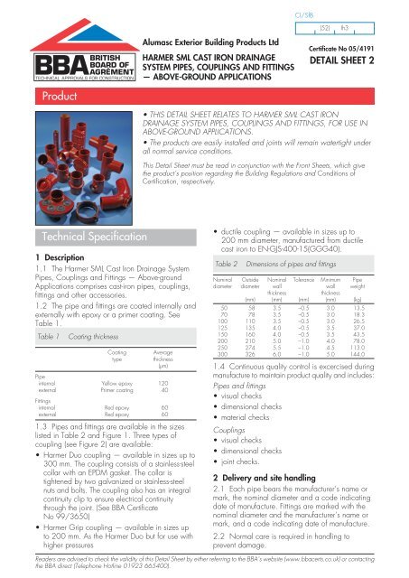
CI/SfB (52) Ih3 Alumasc Exterior Building Products Ltd HARMER SML CAST IRON DRAINAGE SYSTEM PIPES, COUPLINGS AND FITTINGS — ABOVE-GROUND APPLICATIONS Certificate No 05/4191 DETAIL SHEET 2 Product • THIS DETAIL SHEET RELATES TO HARMER SML CAST IRON DRAINAGE SYSTEM PIPES, COUPLINGS AND FITTINGS, FOR USE IN ABOVE-GROUND APPLICATIONS. • The products are easily installed and joints will remain watertight under all normal service conditions. This Detail Sheet must be read in conjunction with the Front Sheets, which give the product’s position regarding the Building Regulations and Conditions of Certification, respectively. Technical Specification 1 Description 1.1 The Harmer SML Cast Iron Drainage System Pipes, Couplings and Fittings — Above-ground Applications comprises cast-iron pipes, couplings, fittings and other accessories. 1.2 The pipe and fittings are coated internally and externally with epoxy or a primer coating. See Table 1. Table 1 Coating thickness Coating type Average thickness (µm) Pipe internal Yellow epoxy 120 external Primer coating 40 Fittings internal Red epoxy 60 external Red epoxy 60 1.3 Pipes and fittings are available in the sizes listed in Table 2 and Figure 1. Three types of coupling (see Figure 2) are available: • Harmer Duo coupling — available in sizes up to 300 mm. The coupling consists of a stainless-steel collar with an EPDM gasket. The collar is tightened by two galvanized or stainless-steel nuts and bolts. The coupling also has an integral continuity clip to ensure electrical continuity through the joint. (See BBA Certificate No 99/3650) • Harmer Grip coupling — available in sizes up to 200 mm. As the Harmer Duo but for use with higher pressures • ductile coupling — available in sizes up to 200 mm diameter, manufactured from ductile cast iron to EN-GJS-400-15(GGG40). Table 2 Dimensions of pipes and fittings Nominal Outside Nominal Tolerance Minimum Pipe diameter diameter wall wall weight thickness thickness (mm) (mm) (mm) (mm) (kg) 50 58 3.5 –0.5 3.0 13.5 70 78 3.5 –0.5 3.0 18.3 100 110 3.5 –0.5 3.0 26.5 125 135 4.0 –0.5 3.5 37.0 150 160 4.0 –0.5 3.5 43.5 200 210 5.0 –1.0 4.0 78.0 250 274 5.5 –1.0 4.5 113.0 300 326 6.0 –1.0 5.0 144.0 1.4 Continuous quality control is excercised during manufacture to maintain product quality and includes: Pipes and fittings • visual checks • dimensional checks • material checks Couplings • visual checks • dimensional checks • joint checks. 2 Delivery and site handling 2.1 Each pipe bears the manufacturer’s name or mark, the nominal diameter and a code indicating date of manufacture. Fittings are marked with the nominal diameter and the manufacturer’s name or mark, and a code indicating date of manufacture. 2.2 Normal care is required in handling to prevent damage. Readers are advised to check the validity of this Detail Sheet by either referring to the BBA’s website (www.bbacerts.co.uk) or contacting the BBA direct (Telephone Hotline 01923 665400).
- Page 2 and 3: Figure 1 Fittings and dimensions SM
- Page 4 and 5: Figure 1 Fittings and dimensions (c
- Page 6 and 7: Figure 1 Fittings and dimensions (c
- Page 8 and 9: Figure 2 Coupling dimension Grip ri
- Page 10 and 11: Technical Investigations The follow
- Page 12: British Board of Agrément P O Box
CI/SfB<br />
(52) Ih3<br />
Alumasc Exterior Building Products Ltd<br />
HARMER <strong>SML</strong> CAST IRON DRAINAGE<br />
SYSTEM PIPES, COUPLINGS AND FITTINGS<br />
— ABOVE-GROUND APPLICATIONS<br />
Certificate No 05/4191<br />
DETAIL SHEET 2<br />
Product<br />
• THIS DETAIL SHEET RELATES TO HARMER <strong>SML</strong> CAST IRON<br />
DRAINAGE SYSTEM PIPES, COUPLINGS AND FITTINGS, FOR USE IN<br />
ABOVE-GROUND APPLICATIONS.<br />
• The products are easily installed and joints will remain watertight under<br />
all normal service conditions.<br />
This Detail Sheet must be read in conjunction with the Front Sheets, which give<br />
the product’s position regarding the Building Regulations and Conditions of<br />
Certification, respectively.<br />
Technical Specification<br />
1 Description<br />
1.1 The <strong>Harmer</strong> <strong>SML</strong> <strong>Cast</strong> <strong>Iron</strong> <strong>Drainage</strong> System<br />
Pipes, Couplings and Fittings — Above-ground<br />
Applications comprises cast-iron pipes, couplings,<br />
fittings and other accessories.<br />
1.2 The pipe and fittings are coated internally and<br />
externally with epoxy or a primer coating. See<br />
Table 1.<br />
Table 1<br />
Coating thickness<br />
Coating<br />
type<br />
Average<br />
thickness<br />
(µm)<br />
Pipe<br />
internal Yellow epoxy 120<br />
external Primer coating 40<br />
Fittings<br />
internal Red epoxy 60<br />
external Red epoxy 60<br />
1.3 Pipes and fittings are available in the sizes<br />
listed in Table 2 and Figure 1. Three types of<br />
coupling (see Figure 2) are available:<br />
• <strong>Harmer</strong> Duo coupling — available in sizes up to<br />
300 mm. The coupling consists of a stainless-steel<br />
collar with an EPDM gasket. The collar is<br />
tightened by two galvanized or stainless-steel<br />
nuts and bolts. The coupling also has an integral<br />
continuity clip to ensure electrical continuity<br />
through the joint. (See BBA Certificate<br />
No 99/3650)<br />
• <strong>Harmer</strong> Grip coupling — available in sizes up<br />
to 200 mm. As the <strong>Harmer</strong> Duo but for use with<br />
higher pressures<br />
• ductile coupling — available in sizes up to<br />
200 mm diameter, manufactured from ductile<br />
cast iron to EN-GJS-400-15(GGG40).<br />
Table 2<br />
Dimensions of pipes and fittings<br />
Nominal Outside Nominal Tolerance Minimum Pipe<br />
diameter diameter wall wall weight<br />
thickness<br />
thickness<br />
(mm) (mm) (mm) (mm) (kg)<br />
50 58 3.5 –0.5 3.0 13.5<br />
70 78 3.5 –0.5 3.0 18.3<br />
100 110 3.5 –0.5 3.0 26.5<br />
125 135 4.0 –0.5 3.5 37.0<br />
150 160 4.0 –0.5 3.5 43.5<br />
200 210 5.0 –1.0 4.0 78.0<br />
250 274 5.5 –1.0 4.5 113.0<br />
300 326 6.0 –1.0 5.0 144.0<br />
1.4 Continuous quality control is excercised during<br />
manufacture to maintain product quality and includes:<br />
Pipes and fittings<br />
• visual checks<br />
• dimensional checks<br />
• material checks<br />
Couplings<br />
• visual checks<br />
• dimensional checks<br />
• joint checks.<br />
2 Delivery and site handling<br />
2.1 Each pipe bears the manufacturer’s name or<br />
mark, the nominal diameter and a code indicating<br />
date of manufacture. Fittings are marked with the<br />
nominal diameter and the manufacturer’s name or<br />
mark, and a code indicating date of manufacture.<br />
2.2 Normal care is required in handling to<br />
prevent damage.<br />
Readers are advised to check the validity of this Detail Sheet by either referring to the BBA’s website (www.bbacerts.co.uk) or contacting<br />
the BBA direct (Telephone Hotline 01923 665400).
Figure 1<br />
Fittings and dimensions<br />
<strong>SML</strong> — Pipe L = 3000 mm<br />
DN<br />
kg<br />
50 13.5<br />
70 18.3<br />
100 26.5<br />
125 37.0<br />
150 43.5<br />
200 78.0<br />
250 113.0<br />
300 144.0<br />
<strong>SML</strong> — double branch 45°<br />
DN X 1<br />
X 2<br />
X 3<br />
kg<br />
100 x 100 260 190 190 4.0<br />
150 x 100 280 225 225 8.4<br />
150 x 150 355 265 265 12.6<br />
200 x 200 455 340 340 24.0<br />
<strong>SML</strong> — double branch 70°<br />
<strong>SML</strong> — reducers<br />
DN A L kg<br />
70 x 50 10 75 0.5<br />
100 x 50 25 80 0.9<br />
100 x 70 16 85 0.9<br />
125 x 50 38.5 85 1.4<br />
125 x 70 28.5 90 1.5<br />
125 x 100 12.5 95 1.5<br />
150 x 50 51 95 2.0<br />
150 x 70 41 100 2.0<br />
150 x 100 25 105 2.2<br />
150 x 125 12.5 110 2.2<br />
200 x 100 50 115 4.1<br />
200 x 125 37.5 120 4.1<br />
200 x 150 25 125 4.3<br />
250 x 150 57 140 6.8<br />
250 x 200 32 145 7.0<br />
300 x 150 83 150 10.7<br />
300 x 200 58 160 11.4<br />
300 x 250 26 170 12.4<br />
DN X 1<br />
X 2<br />
X 3<br />
L kg<br />
100 x 100 x 100 85 130 130 215 3.5<br />
125 x 100 x 100 85 145 145 225 5.0<br />
<strong>SML</strong> — double branch 88° (1)<br />
DN X 1<br />
X 2<br />
X 3<br />
X 4<br />
X 5<br />
L kg<br />
100 x 50 x 50 100 100 105 80 80 180 2.2<br />
(94) (94) (76) (76) (170)<br />
100 x 70 x 70 102 102 110 88 88 190 2.7<br />
100 x 100 x 100 120 120 120 110 118 230 3.2<br />
(115) (115) (115) (105) (105) (220)<br />
150 x 100 x 70 130 130 130 215 115 245 6.3<br />
150 x 100 x 100 130 145 145 225 115 245 7.1<br />
<strong>SML</strong> — single bossed pipe 88°<br />
DN X kg<br />
50 150 1.2<br />
70 146 1.6<br />
100 153 2.1<br />
150 175 3.8<br />
<strong>SML</strong> — corner branch 88°<br />
DN X 1<br />
X 2<br />
X 3<br />
L kg<br />
100 x 70 x 70 102 88 110 190 2.7<br />
100 x 100 x 100 115 105 115 220 3.4<br />
125 x 70 x 70 107 93 125 200 3.7<br />
125 x 100 x 100 125 110 130 235 5.0<br />
150 x 100 x 100 130 115 145 245 7.1<br />
<strong>SML</strong> — double or corner bossed pipe 90°<br />
DN X kg<br />
100 155 2.9<br />
<strong>SML</strong> — corner branch 88° with long spigot<br />
DN X 1<br />
X 2<br />
X 3<br />
L K (2) kg<br />
100 x 100 x 100 325 105 115 430 210 5.2<br />
2
Figure 1<br />
Fittings and dimensions (continued)<br />
<strong>SML</strong> — bearing ring with rubber gasket for downpipe supports<br />
<strong>SML</strong> — branch 88° with long spigot<br />
DN X 1<br />
X 2<br />
X 3<br />
L K (2) kg<br />
100 x 100 325 105 115 430 210 4.6<br />
DN D 2<br />
D 1<br />
A B C<br />
(3)<br />
kg<br />
50 61 93 193 148 25 33 0.8<br />
70 81.5 114 214 166 26 33 1.0<br />
100 115 147 250 202 28 33 1.3<br />
125 138 171 274 225.5 28 33 1.5<br />
150 163 199 301 253.5 30 33 2.0<br />
200 215 250 360 310.5 30 36 3.0<br />
250 280 344 442 392 34 40 5.6<br />
300 332 393 495 445 39 40 7.4<br />
<strong>SML</strong> — parallel branch<br />
DN X 1<br />
X 2<br />
X 3<br />
X 4<br />
L K (2) kg<br />
100 x 70 100 300 175 125 400 125 6.5<br />
<strong>SML</strong> — short double bend 88°<br />
DN X 1<br />
X 2<br />
X 3<br />
kg<br />
50 50 100 121 1.2<br />
70 60 120 145 1.8<br />
100 70 140 170 3.2<br />
125 80 160 195 4.6<br />
150 90 180 219 7.0<br />
<strong>SML</strong> — long double bend 88°<br />
DN X 1<br />
X 2<br />
X 3<br />
kg<br />
<strong>SML</strong> — combination branch<br />
DN X 1<br />
X 2<br />
X 3<br />
X 4<br />
kg<br />
100 x 100 x 70 115 140 130 70 4.5<br />
100 x 100 x 100 115 140 140 70 5.0<br />
70 60 301 273 3.2<br />
100 70 312 291 4.8<br />
125 80 322 308 6.8<br />
150 90 334 326 9.6<br />
<strong>SML</strong> — S-bends offset 65 mm<br />
DN X L kg<br />
100 70 205 2.5<br />
<strong>SML</strong> — downpipe supports<br />
DN D L X kg<br />
50 87 200 96 1.3<br />
70 106 200 96 1.6<br />
100 145 200 96 2.3<br />
125 170 200 96 3.0<br />
150 195 200 96 4.0<br />
200 245 200 96 6.0<br />
250 340 300 146 19.5<br />
300 390 300 146 25.5<br />
<strong>SML</strong> — S-bends offset 130 mm<br />
DN X L kg<br />
100 70 270 3.5<br />
3
Figure 1<br />
Fittings and dimensions (continued)<br />
<strong>SML</strong> — S-bends offset 200 mm<br />
DN X L kg<br />
100 70 340 4.5<br />
<strong>SML</strong> — bend 45° with 250 mm spigot<br />
DN X 1<br />
X 2<br />
K kg<br />
70 250 60 190 2.6<br />
100 250 70 180 4.2<br />
<strong>SML</strong> — single branch 45° (1)<br />
DN X 1<br />
X 2<br />
X 3<br />
L kg<br />
50 x 50 50(45) 135(115) 135(115) 185(160) 1.4(1.2)<br />
70 x 50 40 150(130) 150(130) 190(170) 1.6<br />
70 x 70 55 160(145) 160(145) 215(200) 2.3(2.1)<br />
100 x 50 35(30) 165(150) 165(150) 200(180) 2.5(2.3)<br />
100 x 70 50(45) 185(170) 185(170) 235(215) 3.3(3.0)<br />
100 x 100 70 205(190) 205(190) 275(260) 4.2(3.8)<br />
125 x 50 20 185(170) 185(170) 205(190) 3.4(3.2)<br />
125 x 70 40 200(185) 200(185) 240(225) 4.3(4.0)<br />
125 x 100 60 220(210) 220(210) 280(270) 5.2(5.0)<br />
125 x 125 80(75) 240(230) 240(230) 320(305) 6.4(6.1)<br />
150 x 70 30 215(205) 215(205) 245(235) 5.6(5.3)<br />
150 x 100 55 240(225) 240(225) 295(280) 6.8(6.5)<br />
150 x 125 70 255(245) 255(245) 325(315) 8.0(7.7)<br />
150 x 150 90 265 265 355 9.2<br />
200 x 70 15 240(235) 240(235) 255(250) 8.1(8.0)<br />
200 x 100 40 265(260) 265(260) 305(300) 10.0(9.8)<br />
200 x 125 55 280 280 335 11.9<br />
200 x 150 75 300 300 375 13.3<br />
200 x 200 115 340 340 455 17.2<br />
250 x 100 15 310(305) 310(305) 325(320) 15.4<br />
250 x 125 35 335(330) 335(330) 370(365) 17.7<br />
250 x 150 55 350 350 405 20.2<br />
250 x 200 90 385(380) 385(380) 475(470) 25.1(24.8)<br />
250 x 250 130 430 430 560 31.5<br />
300 x 100 5 345 345 350 22.0<br />
300 x 125 15 360 360 375 23.9<br />
300 x 150 35 380 380 415 26.9<br />
300 x 200 70 415 440 485 34.0<br />
300 x 250 115 465 465 580 42.1<br />
300 x 300 155 505 505 660 50.1<br />
<strong>SML</strong> — bend 88° with 250 mm spigot<br />
DN X 1<br />
X 2<br />
K kg<br />
70 250 90 160 2.8<br />
100 250 110 140 4.6<br />
<strong>SML</strong> — single branch 70°<br />
DN X 1<br />
X 2<br />
X 3<br />
L kg<br />
<strong>SML</strong> — bend 135° for ventilation<br />
DN X L K kg<br />
100 312 150 100 5.0<br />
50 x 50 55 80 80 135 0.9<br />
70 x 50 55 90 90 145 1.2<br />
70 x 70 70 100 100 170 1.6<br />
100 x 50 55 110 100 155 1.9<br />
100 x 70 70 120 110 180 2.3<br />
100 x 100 85 130 130 215 3.0<br />
125 x 50 55 120 110 165 2.7<br />
125 x 70 70 130 120 190 3.2<br />
125 x 100 85 145 140 225 4.8<br />
125 x 125 100 155 155 255 4.8<br />
150 x 100 85 155 150 235 5.3<br />
150 x 125 100 170 165 265 6.2<br />
150 x 150 115 180 180 285 7.2<br />
200 x 100 85 185 170 255 8.6<br />
200 x 125 100 195 185 285 9.8<br />
4
Figure 1<br />
Fittings and dimensions (continued)<br />
<strong>SML</strong> — single bend 45°<br />
<strong>SML</strong> — single branch 88°<br />
DN X 1<br />
X 2<br />
X 3<br />
L kg<br />
50 x 50 79 66 80 145 0.9<br />
70 x 50 83 72 90 155 1.4<br />
70 x 70 97 83 95 180 1.7<br />
100 x 50 94 76 105 170 2.1<br />
100 x 70 102 88 110 190 2.4<br />
100 x 100 115 105 120 220 2.9<br />
125 x 50 98 82 120 180 3.0<br />
125 x 70 107 93 125 200 3.4<br />
125 x 100 125 110 130 235 4.0<br />
125 x 125 137 123 135 260 4.6<br />
150 x 50 100 100 140 200 4.4<br />
150 x 100 130 115 145 245 5.5<br />
150 x 125 147 128 150 275 6.2<br />
150 x 150 158 142 155 300 6.9<br />
DN X kg<br />
50 50 0.5<br />
70 60 0.9<br />
100 70 1.6<br />
125 80 2.3<br />
150 90 3.5<br />
200 110 6.5<br />
250 130 10.3<br />
300 155 17.3<br />
<strong>SML</strong> — single bend 68°<br />
DN X kg<br />
50 65 0.7<br />
70 75 1.1<br />
100 90 1.9<br />
125 105 2.9<br />
150 120 4.9<br />
200 145 7.7<br />
<strong>SML</strong> — swept entry access branch 88°<br />
DN X 1<br />
X 2<br />
K kg<br />
70 x 70 210 80 130 2.5<br />
100 x 50 204 90 120 3.0<br />
100 x 70 221 90 142 3.5<br />
100 x 100 270 102 150 4.3<br />
150 x 100 300 117 202 10.4<br />
150 x 150 400 140 260 13.9<br />
<strong>SML</strong> — single bend 88°<br />
DN X kg<br />
40 70 0.5<br />
50 75 0.7<br />
70 90 1.2<br />
100 110 2.1<br />
125 125 3.3<br />
150 145 4.9<br />
200 180 8.8<br />
<strong>SML</strong> — single bend 15°<br />
DN X kg<br />
50 40 0.4<br />
70 45 0.6<br />
100 50 1.0<br />
125 60 1.7<br />
150 65 2.5<br />
200 80 4.6<br />
<strong>SML</strong> — short radius access bend 88°<br />
DN X kg<br />
70 90 1.8<br />
100 110 3.3<br />
150 145 6.1<br />
<strong>SML</strong> — single bend 30°<br />
DN X kg<br />
50 45 0.5<br />
70 50 0.7<br />
100 60 1.3<br />
125 70 2.0<br />
150 80 3.0<br />
200 95 5.4<br />
250 110 9.7<br />
300 130 15.5<br />
<strong>SML</strong> — long radius access bend 88°<br />
DN X 1<br />
X 2<br />
X 3<br />
kg<br />
100 269 269 180 5.5<br />
5
Figure 1<br />
Fittings and dimensions (continued)<br />
<strong>SML</strong> — flanged connector<br />
DN D 1<br />
D 2<br />
B K (4) screws kg<br />
8pcs<br />
100 220 18 24 180 M16 5.8<br />
125 250 18 26 210 M16 8.0<br />
150 285 22 26 240 M20 9.8<br />
200 340 22 26 295 M20 14.5<br />
<strong>SML</strong> —Tecotect-se-Ü seal (for connecting <strong>SML</strong> to stoneware socket)<br />
DN<br />
100<br />
125<br />
150<br />
200<br />
<strong>SML</strong> — sleeved connector<br />
DN D 1<br />
D 2<br />
L M DE kg<br />
100 144 125.5 250 40 110 3.3<br />
125 172 151.5 250 42.5 135 4.6<br />
150 201 178.5 250 45 160 6.1<br />
<strong>SML</strong> —stoneware connecting ring (to cast iron)<br />
DN<br />
100<br />
125<br />
150<br />
200<br />
<strong>SML</strong> — stoneware connector<br />
DN d kg<br />
100 159 ± 2.0 4.9<br />
125 187 ± 3.5 6.7<br />
150 218 ± 3.5 9.7<br />
200 278 ± 3.5 13.3<br />
250 338 ± 4.0 16.0<br />
300 395 ± 4.0 19.0<br />
<strong>SML</strong> —Tecotect-se (for connecting <strong>SML</strong> socket to stoneware)<br />
DN<br />
100<br />
125<br />
150<br />
200<br />
Plugs<br />
DN L kg<br />
<strong>SML</strong> —stoneware transition ring (for connecting <strong>SML</strong> to stoneware)<br />
DN<br />
100<br />
125<br />
150<br />
200<br />
50 30 0.2<br />
70 35 0.4<br />
100 40 0.5<br />
125 45 1.1<br />
150 50 1.7<br />
200 60 3.1<br />
250 70 6.0<br />
300 80 9.5<br />
6
Figure 1<br />
Fittings and dimensions (continued)<br />
Plugs<br />
DN<br />
kg<br />
100 1.15<br />
125 1.57<br />
150 2.19<br />
200 3.41<br />
<strong>SML</strong> — short pipe with access door<br />
DN A B D L kg<br />
50 59 105 53 190 2.3<br />
70 69 125 73 210 2.9<br />
100 84 159 104 260 5.0<br />
<strong>SML</strong> — rainwater pipe syphon<br />
DN a b I 1<br />
I 2<br />
I 3<br />
kg<br />
70 195 90 472 80 312 9.0<br />
100 276 124 588 90 408 18.5<br />
125 344 144 687 100 487 28.5<br />
150 374 179 742 110 522 38.0<br />
<strong>SML</strong> — short pipes with rectangular access door (1)<br />
DN A B C D E L kg<br />
100 83 160 100 200 230 340 7.6<br />
(320)<br />
125 101 190 125 225 255 370 10.3<br />
(355)<br />
150 112 215 150 250 280 395 14.5<br />
200 137 262 200 300 330 465 22.0<br />
250 170 330 259 350 426 570 36.5<br />
(380) (540)<br />
300 195 380 309 400 476 640 51.0<br />
(430) (610)<br />
(1) The value in brackets represents the figure given in DIN 19522 : 2000<br />
before revision to bring it into line with that in BS EN 877 : 1999.<br />
<strong>SML</strong> — pipe with wall flange<br />
DN L kg<br />
(2) Dimensions for maximum cut-back.<br />
(3) Obsolete model.<br />
(4) Eight holes PN6/PN10 as per EN 1092-2 : 1997.<br />
100 600 8.8<br />
<strong>SML</strong> — pipe with sealing flange<br />
DN A D 1<br />
D 2<br />
kg kg<br />
without with<br />
clamp flange clamp flange<br />
70 156 160 202 7.6 9.2<br />
100 191 190 230 9.0 11.6<br />
125 215 215 260 12.9 16.4<br />
150 235 240 280 14.7 18.5<br />
7
Figure 2<br />
Coupling dimension<br />
Grip ring<br />
<strong>Harmer</strong> Grip<br />
<strong>SML</strong> — ductile cast-iron coupling<br />
DN H D L 1<br />
L 2<br />
kg Torque<br />
(Nm)<br />
50 79 111 50 68 0.6 20<br />
70 89 132 50 68 0.7 20<br />
100 134 168 60 78 1.1 20<br />
150 184 230 71 89 1.9 20<br />
200 231 278 82 100 3.5 20<br />
DN Diameter Height Width Torque<br />
(Nm)<br />
50 69 85 63 8<br />
70 89 105 63 8<br />
100 119 135 63 8<br />
125 144 160 76 8<br />
150 169 185 76 8<br />
200 221 361 76 8<br />
electrical continuity clip<br />
<strong>Harmer</strong> Duo<br />
DN Diameter Height Width Torque<br />
(Nm)<br />
50 69 85.0 63 8<br />
60 84 100.0 63 8<br />
70 89 105.0 63 8<br />
75 91 107.0 63 8<br />
80 104 120.0 63 8<br />
100 119 135.0 63 8<br />
125 144 160.0 76 8<br />
150 169 185.0 76 8<br />
200 221 361.0 76 8<br />
250 283 458.5 147 8<br />
300 335 540.0 147 8<br />
Design Data<br />
3 General<br />
3.1 <strong>Harmer</strong> <strong>SML</strong> <strong>Cast</strong> <strong>Iron</strong> pipes, adaptors<br />
and fittings are satisfactory for use in<br />
domestic, commercial and public buildings<br />
in accordance with BS EN 12056-1, -2 and -3 :<br />
2000 for the conveyance of surface water and<br />
domestic sewage as is permitted to be discharged<br />
into public sewers by the Public Health Act 1936<br />
(England and Wales), and surface water and<br />
sewage as is permitted and defined by the<br />
Sewerage (Scotland) Act 1968 and the Water and<br />
Sewerage Services (Northern Ireland) Order 1973.<br />
3.2 The pipes and fittings are coated with brownred<br />
primer (RAL 3016). A finish coat should be<br />
applied to provide protection for external use.<br />
4 Strength<br />
4.1 <strong>Harmer</strong> <strong>SML</strong> <strong>Cast</strong> <strong>Iron</strong> pipes, adaptors<br />
and fittings will have adequate resistance<br />
to the forms of loading associated with<br />
installation and normal service conditions.<br />
4.2 The products should be protected from<br />
impacts, for example, heavy vehicles, such as<br />
fork-lift trucks used on commercial premises.<br />
5 Performance of joints<br />
5.1 The joints will not be adversely<br />
affected by thermal movement when<br />
correctly made.<br />
5.2 The joints will remain watertight under<br />
conditions of pipeline movement in excess of<br />
those expected to occur in normal good drainage<br />
practice.<br />
8
6 Flow characteristics<br />
6.1 A system comprising the <strong>Harmer</strong> <strong>SML</strong><br />
<strong>Cast</strong> <strong>Iron</strong> pipes, adaptors and fittings will<br />
have satisfactory flow characteristics. Nonswept<br />
branch connections are restricted in<br />
accordance with BS EN 12056-2 : 2000 for<br />
single-stack systems.<br />
6.2 Offsets in the wet portion of a discharge stack<br />
should be avoided. However, if the S-bend offsets<br />
are to be fitted in this position, large radius bends<br />
should be used (see BS EN 12056-2 : 2000).<br />
A ventilation stack may be necessary above and<br />
below the offset (see Figure 3).<br />
(listed in Detail Sheet 1) must be taken into account<br />
at the design stage.<br />
10 Noise<br />
In common with all types of pipe materials,<br />
where the products penetrate a floor or wall,<br />
separating habitable rooms, they should be<br />
in an enclosure to limit sound transmission.<br />
11 Maintenance<br />
Sections of the system can be easily removed<br />
and replaced. Access must be provided in<br />
accordance with BS EN 12056-2 or -3 :<br />
2000.<br />
Figure 3<br />
discharge stack<br />
Offsets in discharge stacks<br />
d<br />
ventilating stack at atmosphere (or<br />
connected to discharge stack above<br />
spill-over level of topmost appliance)<br />
discharge stack<br />
(b)<br />
12 Durability<br />
When used within the conditions and<br />
recommendations given in this Detail Sheet<br />
the products will have a serviceable life<br />
equivalent to conventional cast-iron drainage<br />
systems. When used externally the pipes should be<br />
painted regularly to prevent surface oxidisation.<br />
for ventilated<br />
systems<br />
for ventilated<br />
systems<br />
R is a large as possible (ID x 2 mm min)<br />
d = D/2 or for ventilated systems as required in BS EN 12056-2 : 2000.<br />
F larger than D/2<br />
D > 75 mm (see Note 2 below).<br />
b<br />
(a)<br />
d<br />
R<br />
D<br />
R<br />
Note 1 No branch connections in shaded area unless vented.<br />
Note 2 Arrangement (b) is only possible if D b is 75 mm or larger.<br />
Note 3 No offset venting is required in lightly loaded systems of<br />
up to three storeys in height.<br />
Note 4 Offsets above highest branch connections do not require<br />
venting.<br />
7 Resistance to chemicals<br />
The products will be unaffected by those<br />
type and quantities of chemicals likely to be<br />
found in the effluents defined in section 3.<br />
8 Resistance to elevated temperatures<br />
The products have adequate resistance to<br />
the temperatures likely to occur in the<br />
effluents defined in section 3.<br />
9 Properties in relation to fire<br />
9.1 <strong>Harmer</strong> <strong>SML</strong> <strong>Cast</strong> <strong>Iron</strong> pipes and fittings<br />
are non-combustible.<br />
9.2 The Building Regulations concerning the<br />
prevention of fire spread, eg by by fire-stopping<br />
D b<br />
d<br />
R<br />
R<br />
Installation<br />
13 Procedure<br />
13.1 Installation of <strong>Harmer</strong> <strong>SML</strong> <strong>Cast</strong> <strong>Iron</strong><br />
<strong>Drainage</strong> System Pipes, Couplings and Fittings —<br />
Above-ground Applications should be in<br />
accordance with BS EN 12056-1, -2, -3 and -5 :<br />
2000 and the manufacturer’s Specifier’s manual.<br />
Pipes<br />
13.2 Pipes must be adequately supported at every<br />
connection and at a maximum spacing of 2 m for<br />
both horizontally and vertically. In buildings of up<br />
to five floors, downpipes must be secured against<br />
declining by a downpipe support installed just<br />
above the basement ceiling. In buildings higher<br />
than five floors, an additional downpipe support<br />
must be installed for every fifth floor.<br />
13.3 Horizontal pipes must be fastened at every<br />
change in direction or branch. Pipes attached to<br />
pendula must be secured at distances of 10 m to<br />
15 m by specific fixed-point brackets. The pipes<br />
must be installed at a gradient of at least 20 mm<br />
per metre.<br />
Couplings<br />
13.4 Installation should be carried out in accordance<br />
with the relevant manufacturer’s instructions.<br />
13.5 Pipe ends should be cut square and cleaned<br />
to ensure a good fit.<br />
13.6 For the ductile coupling, the sealing collar is<br />
inserted, piror to the coupling. Finally, the electrical<br />
continuity screw is tightened.<br />
13.7 When tightening the coupling nuts and<br />
bolts, reference must be made to the correct torque<br />
settings specified (see Figure 2).<br />
D b D<br />
9
Technical Investigations<br />
The following is a summary of the technical<br />
investigations carried out on the <strong>Harmer</strong> <strong>SML</strong> <strong>Cast</strong><br />
<strong>Iron</strong> <strong>Drainage</strong> System Pipes, Couplings and<br />
Fittings — Above-ground Applications.<br />
14 Tests<br />
Tests were carried out to determine:<br />
• effect of elevated temperature cycling, to<br />
BS EN 877 : 1999<br />
• ease of jointing<br />
• machinability.<br />
15 Investigations<br />
15.1 An evaluation of data was made to assess:<br />
• system design<br />
• resistance to chemicals<br />
• practicability of installation<br />
• suitability of materials<br />
• effect of crossflow<br />
• quality of castings<br />
• effect of elevated temperature on pressuretightness<br />
of joints<br />
• compatibility with other paints<br />
• flame resistance<br />
• durability.<br />
15.2 Test data was supplied by MPA NRW<br />
(Germany) to determine in accordance with the<br />
relevant clauses of BS EN 877 : 1999 :<br />
clauses 5.7.2.7 and 5.8.7.<br />
Clause<br />
Surface condition 5.1<br />
External diameter 5.2.1<br />
Wall thickness 5.2.2<br />
Internal diameter of pipes 5.2.3<br />
Ovality 5.2.4<br />
Straightness of pipes 5.2.5<br />
End faces 5.2.6<br />
Length of pipes 5.2.7<br />
Lengths of fittings and sealing zone 5.2.7<br />
Angle of fittings 5.2.8<br />
Mass: pipes and fittings 5.3<br />
Tensile strength 5.4<br />
Brinell hardness 5.5<br />
Ring crush strength of pipes 5.6<br />
Internal coatings<br />
resistance to salt spray 5.7.2.1<br />
resistance to waste water 5.7.2.2<br />
chemical resistance 5.7.2.3<br />
dry coating thickness 5.7.2.4<br />
adhesion 5.7.2.5<br />
resistance to hot water 5.7.2.6<br />
resistance to temperature cycling 5.7.2.7<br />
External coatings 5.7.3<br />
Watertightness of joints<br />
positive internal pressure 5.8.4<br />
positive external pressure 5.8.5<br />
Airtightness<br />
fittings and system 5.8.6<br />
Temperature resistance<br />
fittings and system 5.8.7<br />
Marking 5.11<br />
16 Other investigations<br />
The manufacturing process was examined,<br />
including the methods adopted for quality control,<br />
and details were obtained of the quality and<br />
composition of the materials used.<br />
10
Bibliography<br />
BS EN 877 : 1999 <strong>Cast</strong> iron pipes and fittings,<br />
their joints and accessories for the evacuation of<br />
water from buildings — Requirements, test methods<br />
and quality assurance<br />
BS EN 12056-1 : 2000 Gravity <strong>Drainage</strong><br />
<strong>Systems</strong> inside Buildings — General and<br />
performance requirements<br />
BS EN 12056-2 : 2000 Gravity <strong>Drainage</strong><br />
<strong>Systems</strong> inside Buildings — Sanitary pipework,<br />
layout and calculation<br />
BS EN 12056-3 : 2000 Gravity <strong>Drainage</strong><br />
<strong>Systems</strong> inside Buildings — Roof drainage, layout<br />
and calculation<br />
BS EN 12056-5 : 2000 Gravity <strong>Drainage</strong><br />
<strong>Systems</strong> inside Buildings — Installation and testing,<br />
instructions for operation, maintenance and use<br />
DIN 19522 : 2000 <strong>Cast</strong>-iron drainage pipe and<br />
fittings without sockets (<strong>SML</strong>)<br />
EN 1092-2 : 1997 Flanges and their joints —<br />
Circular flanges for pipes, valves, fittings and<br />
accessories, PN designated — <strong>Cast</strong> iron flanges<br />
On behalf of the British Board of Agrément<br />
Date of issue: 13th January 2005<br />
Chief Executive<br />
11
British Board of Agrément<br />
P O Box No 195, Bucknalls Lane<br />
Garston, Watford, Herts WD25 9BA<br />
Fax: 01923 665301<br />
©2005<br />
e-mail: mail@bba.star.co.uk<br />
website: www.bbacerts.co.uk<br />
For technical or additional information,<br />
contact the Certificate holder (see<br />
front page).<br />
For information about the Agrément<br />
Certificate, including validity and<br />
scope, tel: Hotline 01923 665400,<br />
or check the BBA website.


