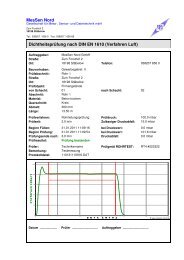
DIN 1999 - 100 - Messen Nord GmbH
DIN 1999 - 100 - Messen Nord GmbH
DIN 1999 - 100 - Messen Nord GmbH

You also want an ePaper? Increase the reach of your titles
YUMPU automatically turns print PDFs into web optimized ePapers that Google loves.
MESSEN NORD <strong>GmbH</strong><br />
Zum Forsthof 2<br />
D-18198 Stäbelow<br />
Tel. : +49 38207 - 656 - 0<br />
FAX: +49 38207 - 656. 66<br />
www.messen-nord.de<br />
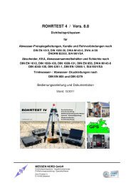
ROHRTEST-4 v. 8.8<br />
Tightness test system<br />
for<br />
Sewers, sewage pipes and pipe connections<br />
acc. to EN 1610, SIA 190 / VSA<br />
Separators, Collectors and Shafts<br />
acc. to EN 1610, EN 858-1, EN 858-2, <strong>DIN</strong> <strong>1999</strong>-<strong>100</strong>, <strong>DIN</strong> 4040-<strong>100</strong>,<br />
EN 12566-1, SIA 190 / VSA<br />
Drinking water / waste water pressure pipes acc. to EN 805
ROHRTEST-4, v. 8.8 MESSEN NORD <strong>GmbH</strong><br />
0. Table of contents Side<br />
1. Application of the test system 4<br />
1.1. Water pressure-test / low-pressure 5<br />
1.2. Water pressure-test / high pressure 5<br />
1.3. Shaft and separator-test in the free-mirror-procedure 6<br />
1.4. Compressed air-test / sleeve-sample 8<br />
2. Technical parameters 11<br />
3.1. General business-parameters 11<br />
3.2. Measuring-equipment WATER / water supply 12<br />
3.3. Measuring-equipment AIR / compressed air-supply 13<br />
3.4. Measuring-equipment VACUUM / hypotension-production 14<br />
3.5. Measuring-equipment HIGH PRESSURE / high pressure-production 15<br />
3.6. Measuring-equipment SHAFT 16<br />
3.7. Measuring-precision of the measuring-facilities / calibration 18<br />
4. Danger-prevention 20<br />
5. Installation 21<br />
5.1. Installation 21<br />
5.2. Installation of the USB-Adapters 22<br />
5.3. Program-configuration 24<br />
5.4. Formation of the individual protocol-head 25<br />
6. Test standards and parameters 27<br />
6.1. Selection of the test procedure and the test standard 27<br />
6.2. Test with water / low-pressure 28<br />
6.2.1. Test parameters for tests of <strong>DIN</strong> EN 1610 28<br />
(Water, low-pressure)<br />
6.2.2. Test parameters for tests of <strong>DIN</strong> <strong>1999</strong>-<strong>100</strong> 29<br />
(Water-level-tests for separators)<br />
6.2.3. Test parameters for tests of <strong>DIN</strong> 4040-<strong>100</strong> 33<br />
(Water-level-tests for fat-separators)<br />
6.3. Test parameters for tests of <strong>DIN</strong> EN 805 36<br />
(Water, high pressure)<br />
6.4. Test parameters for tests with compressed air 37<br />
6.5. Test parameters for special-tests 37<br />
6.6. Test parameters for sleeve-tests 38<br />
6.6.1. Tester administration 39<br />
6.6.2. Sleeve-test with reference-measurement 40<br />
6.6.3. Sleeve-tests of ATV/DWA M 143 slices 6 41<br />
page 2
ROHRTEST-4, v. 8.8 MESSEN NORD <strong>GmbH</strong><br />
7. Test-transaction 42<br />
7.1. Tests with measuring-equipment WATER 42<br />
7.1.1. Preparatory works 42<br />
7.1.2. Test with measuring-equipment WATER 43<br />
7.2. Tests with measuring-equipment HIGH PRESSURE 44<br />
7.2.1. Preparatory works 44<br />
7.2.2. Test-transaction with measuring-equipment HIGH PRESSURE 45<br />
7.3. Tests with measuring-equipment AIR 46<br />
7.3.1. Preparatory works 46<br />
7.3.2. Transaction of the test with compressed air 47<br />
7.3.3. Test of tube-connections / sleeve-test 48<br />
7.4. Tests with the measuring-equipment SHAFT 49<br />
7.4.1. Preparatory works 49<br />
7.4.2. Transaction of the test with the measuring-equipment SHAFT 50<br />
8. Data-concept 51<br />
8.1. Storage of the test reports 51<br />
8.2. Project-administration 52<br />
8.2.1. Transferred by data-continuances, updating of the project-administration 52<br />
8.2.2. Summary from test reports to lists and overview-tables 52<br />
8.3. Preparation and alteration of test report forms 55<br />
8.3.1. Saving hierachy of test report forms 55<br />
8.4. Data take over from test reports 58<br />
8.5. Configuration of the option "GPS" 59<br />
9. Appliance-maintenance, calibrations and function-tests 60<br />
9.1. Appliance-check 60<br />
9.2. Cleaning of the filter of the measuring-equipment WATER 60<br />
9.3. Changeover to winter-business 61<br />
9.4. Test of the appliance-function, own-control 61<br />
9.5. Cleaning of the measuring-equipment SHAFT 61<br />
Installation:<br />
Test standards (tabular transcriptions, work-leaves)<br />
A) <strong>DIN</strong> EN 1610<br />
B) LfW 4.3-6<br />
C) ATV/DWA M 143-6<br />
D) <strong>DIN</strong> <strong>1999</strong>-<strong>100</strong> / EN 858-1<br />
E) <strong>DIN</strong> 4040-<strong>100</strong><br />
page 3
ROHRTEST-4, v. 8.8 MESSEN NORD <strong>GmbH</strong><br />
1. Application of the test system<br />
The test system ROHRTEST-4 allows the computer-aided, automated tightness test<br />
of sewage pipelines, muffs, shafts and separators after the test standards nationally<br />
binding for these installations. In the result of the test, standardized test reports are<br />
produced which document the test course and the test result.<br />
You find a complete list of the test-specific system-components under 2. Systemcomponents<br />
/ delivery capacity:<br />
System-components Test procedures<br />
Control unit with integrated measuringequipment<br />
AIR/VACUUM (RT-ST04)<br />
External measuring equipment AIR<br />
(RT-EXTL)<br />
This unit is required for all Test<br />
procedures, contains measuringequipment<br />
for AIR / VACUUM tests,<br />
supplie unit, data-transformers and test<br />
controller for all measuring-facilities<br />
Tests acc. to EN 1610 (L), ATV/DWA M<br />
143/6, ATV/DWA A 139, ATV/DWA A<br />
142, ÖNORM B2503, SIA 190 / VSA<br />
External Filling and measuring unit for<br />
testing high pipe dimensions, application<br />
directly at the pipe fastener, makes filling<br />
procedure fast and save<br />
Tests acc. to EN 1610 (L), ATV/DWA M<br />
143/6, ATV/DWA A 139, ÖNORM<br />
B2503, SIA 190 / VSA<br />
Measuring-equipment SHAFT (RT-SP04) Shaft and separator-tests acc. to EN<br />
1610, ATV/DWA M 143/6, EN 858-1, EN<br />
858-2, <strong>DIN</strong> <strong>1999</strong>-<strong>100</strong>, <strong>DIN</strong> 4040-<strong>100</strong>, SIA<br />
190/VSA<br />
Measuring-equipment WATER<br />
(RT-WA04)<br />
External water pressure sensor<br />
(RT-EXTW)<br />
Allows water loss tests by automatic<br />
supplying and measuring the lost water.<br />
Unit can keep up a given pressure or a<br />
level in connection with external sensors.<br />
Tests acc. to EN 1610 (W), ATV/DWA M<br />
143/6, ATV/DWA A 139, ÖNORM<br />
B2503, SIA 190 / VSA<br />
Allows in connection with RT-WA04 the<br />
water loss test by keep up the water start<br />
level. Apllication of the pressure sensor<br />
directly at the pipe fastener.<br />
Tests acc. to EN 1610 (W), ATV/DWA M<br />
143/6, ATV/DWA A 139, ÖNORM<br />
B2503, SIA 190 / VSA<br />
page 4
ROHRTEST-4, v. 8.8 MESSEN NORD <strong>GmbH</strong><br />
External water pressure sensor<br />
(nozzle model) (RT-EXTWR)<br />
Allows in connection with RT-WA04 the<br />
water loss test by keep up the water start<br />
level. Apllication of the pressure sensor at<br />
the drain outlet.<br />
Tests acc. to EN 1610 (W), ATV/DWA M<br />
143/6, ATV/DWA A 139, ÖNORM<br />
B2503, SIA 190 / VSA<br />
Dispatcher-box (RT-VBX) allows the automatic water-addition in<br />
connection with the measuring-facilities<br />
SHAFT and WATER at shaft and<br />
separator-tests according to <strong>DIN</strong> <strong>1999</strong>-<br />
<strong>100</strong><br />
Measuring-equipment HIGH PRESSURE<br />
(RT-HD04)<br />
Tests of <strong>DIN</strong> EN 805 as well as. the<br />
former Norm <strong>DIN</strong> 4279 (water, high<br />
pressure)<br />
Air-distribution-unit (RT-LV04) Muffs and stand-tests with compressed<br />
air after ATV/DWA M 143/6, <strong>DIN</strong> EN<br />
1610, Control of the tests and blisterpressure<br />
for Max. 4 Fasteners as well as<br />
a Junction test fastener<br />
Junction test fastener (RT-MU04) Manually driven reel with connectionmanagement<br />
<strong>100</strong> m to the Junction test<br />
fasteners over only one hosemanagement<br />
with interior-lying main lead<br />
for measuring-sensor, air-control and<br />
observation-camera<br />
Optional fade-in of the Test parameter<br />
into the video-picture<br />
page 5
ROHRTEST-4, v. 8.8 MESSEN NORD <strong>GmbH</strong><br />
1.1. Water pressure-test / low-pressure<br />
Configuration A: Water pressure test at the closed system (fastened pipe)<br />
Control unit<br />
RT-ST04<br />
Connection cable<br />
RT-VK10<br />
Standards: EN 1610 „W“<br />
<strong>DIN</strong> 1986 Teil 30<br />
DWA M 143 Teil 6<br />
SIA 190 / VSA<br />
ÖNORM B2503<br />
Special test procedure „W“<br />
Measuring unit WATER<br />
RT-WA04<br />
Test<br />
connection<br />
Water<br />
supply<br />
page 6
ROHRTEST-4, v. 8.8 MESSEN NORD <strong>GmbH</strong><br />
Water pressure-test / low-pressure<br />
Configuration B: Water pressure test at the open system (open water column)<br />
Control unit<br />
RT-ST04<br />
Dispatcher box<br />
RT-VBOX<br />
Standards: EN 1610 „W“<br />
<strong>DIN</strong> 1986 Teil 30<br />
DWA M 143 Teil 6<br />
SIA 190 / VSA<br />
ÖNORM B2503<br />
Special test procedure „W“<br />
Measuring unit WATER<br />
RT-WA04<br />
External pressure sensor<br />
RT-EXTW<br />
Test<br />
connection<br />
Water<br />
supply<br />
page 7
ROHRTEST-4, v. 8.8 MESSEN NORD <strong>GmbH</strong><br />
1.2. Water pressure-test / high pressure<br />
Control unit<br />
RT-ST04<br />
Test standards: EN 805<br />
<strong>DIN</strong> 4279 (become obsolete)<br />
Special test procedure "H"<br />
Measure equipment HIGH<br />
PRESSURE RT-HD04<br />
Test<br />
connect.<br />
page 8
ROHRTEST-4, v. 8.8 MESSEN NORD <strong>GmbH</strong><br />
1.3. Shaft and separator-test in the free-mirror-procedure<br />
Configuration A: Shaft - / separator-test of automatic water-addition<br />
Control unit<br />
RT-ST04<br />
Configuration B: Separator-test with automatic water-addition<br />
Measure equipment<br />
SHAFT RT-SP04<br />
Dispatcher<br />
box RT-VBX<br />
Connection<br />
cable RT-VK10<br />
Sensor cable<br />
RT-SK10<br />
Measure equipment<br />
SHAFT<br />
Control unit<br />
RT-ST04<br />
Measure equipment<br />
WATER RT-WA04<br />
To the<br />
Shaft<br />
Water<br />
supply<br />
page 9
ROHRTEST-4, v. 8.8 MESSEN NORD <strong>GmbH</strong><br />
Configuration C: Separator-test with several level-probes<br />
Sensor cable<br />
RT-SK10<br />
Measure equipment<br />
SHAFT RT-SP04<br />
Control unit<br />
RT-ST04 with<br />
2 add. Meas.ports<br />
Measure equipment<br />
SHAFT RT-SP04<br />
Test standards: EN 858<br />
<strong>DIN</strong> <strong>1999</strong>-<strong>100</strong><br />
<strong>DIN</strong> 4040-<strong>100</strong><br />
EN 1610 "W"<br />
Special test procedure „W“<br />
Measure equipment<br />
SHAFT RT-SP04<br />
1.4. Pipe test with compressed air / measuring equipment AIR/VAKUUM<br />
page 10
ROHRTEST-4, v. 8.8 MESSEN NORD <strong>GmbH</strong><br />
Control unit<br />
RT-ST04<br />
Compressed air<br />
supply<br />
Test standards: EN 1610, Verfahren „L“<br />
DWA M 139<br />
<strong>DIN</strong> 1986/30, DWA M 143/6<br />
ÖNORM B2503<br />
SIA 190 / VSA<br />
Special test procedure „L“<br />
Air distribution unit<br />
RT-LV04<br />
1.5. Pipe test with compressed air / external measuring equipment AIR<br />
page 11
ROHRTEST-4, v. 8.8 MESSEN NORD <strong>GmbH</strong><br />
Control unit<br />
RT-ST04<br />
External measuring<br />
equipment AIR<br />
Test standards: EN 1610, Verfahren „L“<br />
DWA M 139<br />
<strong>DIN</strong> 1986/30, DWA M 143/6<br />
ÖNORM B2503<br />
SIA 190 / VSA<br />
Special test procedure „L“<br />
Compressed air<br />
supply<br />
page 12
ROHRTEST-4, v. 8.8 MESSEN NORD <strong>GmbH</strong><br />
1.6. Compressed air tightness test for pipe junctions<br />
Control unit<br />
RT-ST04<br />
Video Data Box<br />
RT-DBOX<br />
Compressed air<br />
supply<br />
Test standards: ATV/DWA M 139<br />
ATV/DWA M 143-6<br />
EN 1610<br />
ÖNORM B2503<br />
SIA 190 / VSA<br />
Special test procedure „L“<br />
RT-LV04<br />
Compressed air<br />
control unit<br />
Junction test reel<br />
RT-MU04,<br />
house length <strong>100</strong> m,<br />
cable, meter counter and<br />
videotextgenerator integrated<br />
Junction test<br />
fasteners with<br />
integratred<br />
camera<br />
page 13
ROHRTEST-4, v. 8.8 MESSEN NORD <strong>GmbH</strong><br />
1.7. Water tightness test for pipe junctions<br />
Control unit<br />
RT-ST04<br />
Video Data Box<br />
RT-DBOX<br />
Compressed air<br />
supply<br />
Kompressor<br />
Test standards: ATV/DWA M 139<br />
ATV/DWA M 143-6<br />
EN 1610<br />
ÖNORM B2503<br />
SIA 190 / VSA<br />
Special test procedure „W“<br />
RT-LV04<br />
Compressed air<br />
control unit<br />
Junction test reel<br />
RT-MU04,<br />
house length <strong>100</strong> m,<br />
cable, meter counter and<br />
videotextgenerator<br />
integrated<br />
Junction test<br />
fasteners with<br />
integrated camera<br />
page 14
ROHRTEST-4, v. 8.8 MESSEN NORD <strong>GmbH</strong><br />
2. Technical parameters<br />
2.1. General business-parameters for all system-components<br />
Power supply 12V DC (motor vehicle-shelf-net, 16A)<br />
230V 50 Hz (6 A)<br />
Supply takes place over the control unit ST04<br />
Electric connection 12V: Motor vehicle-socket for included cables<br />
230V: Net-socket<br />
External measuring-facilities:<br />
Connection to measuring-equipment<br />
over special-cables<br />
Business-conditions Temperature:<br />
1 ... 40°C, no direct sun-radiation<br />
Humidity:<br />
Control unit until 90 percent of rel. Humidity<br />
not-condenses<br />
Measuring-facilities WATER, HIGH PRESSURE and<br />
SHAFT IP65, the function of the measuring-equipment<br />
SHAFT restricted with moisture-effect.<br />
Transportation and camps- Temperature:<br />
conditions: 1 ... 60°C, measuring-facilities WATER and HIGH<br />
PRESSURE can through complete emptying of water<br />
(business-means), Condensation, or through<br />
replenishing with motor vehicle-frost-protection<br />
sufficient concentration frost-certainly is done.<br />
Humidity:<br />
until not-condenses relative humidity 90 percent<br />
Package:<br />
Appliance-casings are as transportation-package<br />
(Package-service, been not suitable. Additional<br />
protection against push and pressure necessary.<br />
Stack-bar-ness:<br />
Appliance-casings are unpackaged until Max. 3<br />
Appliances stack-bar.<br />
page 15
ROHRTEST-4, v. 8.8 MESSEN NORD <strong>GmbH</strong><br />
2.2. Measuring-equipment WATER / water supply<br />
Operating parameters<br />
Business-medium: Water, fine-filtered<br />
Entrance-pressure-area: - 0,1 ... + 0,5 bar<br />
Exit-work-pressure: Max. 1 bar<br />
Exit-pressure-proof-ness: Max. 2,5 bar, over it irreversible damage<br />
Maximum-flow: 400 l/h<br />
Water supply<br />
Since the measuring-equipment WATER possesses an integrated pump, only a<br />
pressure-loose water-connection is required. The entrance-pressure can .0.1 bar. To<br />
suck in from until tank more deeply situated to 1 m, until +0.5 amount cash (tank lies<br />
until to 5 m higher than the measuring-equipment).<br />
RESPECT! Infringements of the maximum entrance-pressure can lead to<br />
irreversible damages of the appliance as well as to the user's<br />
endangering.<br />
About the capability of the installation not through pressure-garbages in the hosemanagements<br />
as well as it is recommended to the connections to reduce not to<br />
exceed a maximum hose-length of 10 m and a minimal cross-section of 10 mm, not<br />
to under-stride.<br />
2.3. Measuring-equipment AIR / compressed air-supply<br />
Operating parameters<br />
Business-medium: Air<br />
Entrance-pressure-area: 0,1 ... 2,bar 0 above atmospheric pressure<br />
Exit-work-pressure: Max. 0,6 bar<br />
Exit-pressure-proof-ness: Max. 1,5 bar, over it irreversible damage<br />
Maximum-vacuum-stream: 500 l / min (normal-gas)<br />
Protection against damages through over pressure<br />
The form of the filling control unit is on Max. 2 bar to restrict cash, a form is<br />
recommended by about. 0,5-1,0 bar. The pressure-restriction takes place with a<br />
mechanical pressure control as well as. Pressure minimizer, which becomes rear for<br />
the compressor.<br />
For the duration of the test operation, the upholding the form is necessary at the<br />
compressed air-entrance of the filling control unit.<br />
RESPECT! Heed section 4 about the danger-prevention with the contact with<br />
compressed air.<br />
page 16
ROHRTEST-4, v. 8.8 MESSEN NORD <strong>GmbH</strong><br />
2.4. Measuring-equipment VACUUM / hypotension-production<br />
Operating parameters<br />
Business-medium: Air<br />
Entrance-pressure-area: 0,0 ... 1,bar below atmospheric pressure<br />
Exit-work-pressure: Max. 1,bar below atmospheric pressure<br />
Maximum-vacuum-stream: 500 l / min (normal-gas)<br />
Hypotension-production<br />
The production of the hypotension can be gone in for which with customary pressure<br />
(so-called ejectors, jet-procedures) with compressed air or water as energy-bearers<br />
or but with vacuum-suction pumps takes place.<br />
2.5. Measuring-equipment HIGH PRESSURE / high pressure-production<br />
Operating parameters<br />
Business-medium: WATER, fine-filtered<br />
Work-pressure-area: 0 ... 25 bar<br />
Pressure-proof-ness: Max. 40 bar, over it irreversible damage as well as.<br />
Endangering<br />
High pressure-production<br />
The connection to the measuring-equipment HIGH PRESSURE takes place<br />
accordingly following illustration:<br />
High pressure<br />
pump<br />
Pressure liniter<br />
ROHRTEST-4, v. 8.8 MESSEN NORD <strong>GmbH</strong><br />
2.6. Measuring-equipment SHAFT<br />
There are two different test procedures for the use of the ROHRTEST-measurement<br />
uipment SHAFT:<br />
a, level-alteration-measurement<br />
On this occasion the level-alteration is recorded opposite the zero-water-stand at<br />
beginning of the test and is calculated the water-loss-quantity with help of the shaftgeometry.<br />
The pressure-alteration yielding itself through the level-alteration amounts<br />
to at most 5 mbar.<br />
Measuring-area: 50 mm level-alteration<br />
Appliance-technology: Control unit ST04,<br />
Measuring-equipment SHAFT<br />
b, water-loss-compensation<br />
With this Test procedures, the water-level is stopped steadily at the zero-water-stand<br />
over the entire test procedure. The addition of water-losses takes place<br />
automatically, the loss-installment is recorded over the test procedure.<br />
Measuring-area: 0.02 .. 400 l/h loss-installment (loss of 0 is recognized)<br />
Appliance-technology: Control unit ST04,<br />
Measuring-equipment WATER,<br />
Measuring-equipment SHAFT<br />
Measuring<br />
equipment SHAFT<br />
Zero-water-stand<br />
page 18
ROHRTEST-4, v. 8.8 MESSEN NORD <strong>GmbH</strong><br />
Technical parameters<br />
Connection: over connection-cables at reason-appliance ROHRTEST 4,<br />
Supply with protection-small-tension of the reason-appliance,<br />
maximum cable-length 80m<br />
Denseness- <strong>DIN</strong> EN 1610, method "W"<br />
tests: <strong>DIN</strong> <strong>1999</strong>-<strong>100</strong><br />
<strong>DIN</strong> 4040-<strong>100</strong><br />
<strong>DIN</strong> 4261-1<br />
<strong>DIN</strong> EN 12566-1<br />
Special-tests (free parameters)<br />
Measuring-area: Max. 50 mm level-alteration<br />
entspr. Max. 39 l loss of DN <strong>100</strong>0<br />
entspr. Max. 25 l loss of DN 800<br />
Dissolution: 0.01 mm level-alteration<br />
Precision: +/-0.2 mm with expired or not existing calibration<br />
+/-0.1 mm with valid calibration, See section 3.7<br />
+/-0.03 mm with parallel temperature measurement and valid<br />
calibration, See section 3.7<br />
Please heed:<br />
The stated measuring-precision is gained by the measuring<br />
instrument under unfavorable conditions only 15 min after positioning<br />
and switching on in the span required for this stabilization-process<br />
being main from the temperature-difference between the place of the<br />
storage as well as the transportation and the place of the use<br />
dependent.<br />
Delivery capacity: Measuring-equipment "shaft" with tripod and level unit,<br />
extension-tubes 0,5 m and 1,0 m, Calibration report<br />
The measuring-equipment SHAFT (ROHRTEST SP04) possesses the admission<br />
of the LGA Würzburg for the test of fusible-ness-separators of the Prüfnorm<br />
<strong>DIN</strong> in <strong>1999</strong>-<strong>100</strong>.<br />
We like to send you a copy of the certificate on demand.<br />
page 19
ROHRTEST-4, v. 8.8 MESSEN NORD <strong>GmbH</strong><br />
2.7. Measuring-precision of the measuring-facilities / calibration<br />
Measuringequipment<br />
Einstellgenauigkeit<br />
Test pressure /<br />
level<br />
Measuring-precision<br />
pressure - / levelwaste<br />
AIR / VACUUM +/- 5 mbar +/- 1 mbar -<br />
Measuring-precision<br />
water-loss<br />
WATER +/- 10 mbar +/- 2 mbar 5% from the<br />
measurement in the<br />
area 0,02-400 l/h<br />
HIGH<br />
PRESSURE<br />
+/- 200 mbar +/- 15 mbar 5% from the<br />
measurement in the<br />
area 0,02-400 l/h<br />
SHAFT +/- 0,2 mm Up to +/- 0,03 mm<br />
See section 2.6!<br />
Calibration of measurement equipments AIR, WATER, HIGH PRESSURE<br />
The measuring-facilities of the system ROHRTEST are basing on high-quality<br />
sensors for pressure and water flow which are subjected extensive tests before<br />
delivery.<br />
In order to support the users of the installation in the proof of the precision opposite<br />
her/its/their clients, all measuring-facilities are calibrated. The Calibration reports<br />
belong to the delivery capacity of the respective installations.<br />
Through the application of DKD-certificated calibration equipment the retracing of the<br />
measurements to the German national norm is given.<br />
A repetition of the calibration is recommended by the manufacturer in distances of 1<br />
years, please contact for this purpose your supplier as well as. the appliancemanufacturer.<br />
Influence of the atmospheric pressure on the pressure-measurements<br />
Through this, measuring-proceeding would use, the recorded test pressure remains<br />
independently from the atmospheric pressure, d.h. Weather-changes, on the agenda<br />
wind and similar factors don't have any influence on the test result.<br />
Since the water-loss as well as. Pressure-waste from a leaky tube-wall as well as. a<br />
tube-connection dependent on the difference-pressure of inner and outside-pressure<br />
is, the test pressure (inner-pressure) should be put in relatively to the atmospheric<br />
pressure (outside-pressure).<br />
In order to enable this, the functions "Calibration atmospheric pressure" are existing<br />
for the measurement equipments AIR, WATER and HIGH PRESSURE. By<br />
implementation of these functions, the exact reference of the test pressure to the<br />
current environment-atmospheric pressure is guaranteed directly before beginning of<br />
the tube-test.<br />
-<br />
page 20
ROHRTEST-4, v. 8.8 MESSEN NORD <strong>GmbH</strong><br />
4. Danger-prevention<br />
Danger by electric stream<br />
The test system ROHRTEST works with a supply of 230V AC why the danger of the<br />
injury of electric electric jolt emerges with improper application.<br />
Run the appliance if you use the 230V-supply, only at as prescribed grounded<br />
protection-contact-sockets!<br />
Use only the included original supply cable ! If these cable is damaged don’t use it<br />
until professional repair.<br />
Replace the electrical fuses only with such with same parameters.<br />
The control unit is not waterproof. The appliance is only allowed in surroundings with<br />
fewer than 90 percent humidity (not-condenses).<br />
If water penetrated into the device, so another application is forbidden.<br />
The control unit don’t contain any through the user to replacing part / modules.<br />
With disturbances of the device function please contact the repair-service.<br />
A usage of the device with opened casing (decreased front-plate) is forbidden.<br />
Danger by compressed air<br />
The test with compressed air rescues with improper handling of the devices securityrisks<br />
for the user.<br />
For the application of the Fasteners (dense-disks) are the application-rules of the<br />
respective manufacturers to heed.<br />
All fasteners / hoses / connectors are to be checked for sure seat before pressure<br />
application.<br />
As long as the pipeline is under pressure, present people have to choose her/its/their<br />
residence so that they cannot be hurt by for example away-skidded fasteners.<br />
Pipeline, hoses and measuring-equipment are to be aired before the solving the<br />
connections.<br />
page 21
ROHRTEST-4, v. 8.8 MESSEN NORD <strong>GmbH</strong><br />
5. Installation<br />
5.1. Installation and Starting up<br />
• Put the control unit ST04 on the suitcase-acreage and open the suitcase-cover,<br />
post the suitcase-cover<br />
• Remove the cap from the connection-socket “supply” and connect the supplycable<br />
"230V AC", you bolt the clutch<br />
• Connect the power plug to an as prescribed installed protection-contact-socket<br />
(230V AC)<br />
• Switch the main-counter on position in "1", (230V AC) the control-ads "12V DC"<br />
and "24V DC" now must shine, the control-ad "controllers" must with a frequency<br />
of about. 1 Hz blink<br />
• Now connect the measuring-equipment, which you want to use, to the connection<br />
"equipment" and proceed, as described in section 7 further<br />
page 22
ROHRTEST-4, v. 8.8 MESSEN NORD <strong>GmbH</strong><br />
5.2. Installation of the USB-Adapters<br />
To the installation of the drivers - software must possess you administrator-rights<br />
under Windows 2000 and Windows XP, there some files into this Windows - systemtable<br />
is copied. If you don't own any administrator-right, you please turn to the person<br />
responsible for it.<br />
Driver-installation<br />
1.) Put the included CD into her/its/their CD-drive.<br />
2.) Close ggf. the automatically appearing installation-window.<br />
3.) Start the Windows-Explorer and select the CD-drive.<br />
4.) Change 1.1 TO RS232 Converter\PC Driver" into the table "USB.<br />
5.) Double-click the file "Setup.EXES." The installation starts.<br />
6.) Click on "further" and "completing" is finished until the installation.<br />
7.) Connect the USB-Adapter with the computer. Windows installs him/it<br />
corresponding drivers automatically.<br />
8.) Windows recognizes the new hardware automatically and shows hardware<br />
him/it-Installation-assistants<br />
9.) If you choose the automatic installation (recommended), that becomes driver,<br />
installed with the installation-assistant, possibly a latest-Art of the computer is<br />
necessary<br />
More exact operating system-specific instructions are in the included one<br />
To find (only in English available) installation-instruction on the Treiber-CD.<br />
Configuration of the adapter (Windows - appliance-managers)<br />
1.) Open the system-control (start (attitudes) system-control) and double-click on<br />
"system."<br />
2.) Change "hardware" to the file and choose "appliance-managers."<br />
3.) Open the section "connections COM and LPT" in that you click on the "plus-<br />
sign."<br />
4.) You/they see to Serial adapter (COM x)" a component "USB there, with what<br />
the "x" for the currently assigned Comport - number stands. Select this Comport<br />
in the measuring-software as interface and test the communication with the<br />
connected, switched on appliance in that you start a measurement.<br />
page 23
ROHRTEST-4, v. 8.8 MESSEN NORD <strong>GmbH</strong><br />
5.) To altering the Comport - clicks you to Serial adapters (COM x)" number on<br />
the component "USB in the appliance-manager with the right mouse-button and<br />
picks the point "qualities" you in the menu.<br />
6.) Change "connection-attitudes" to the file and press on the button of "widening<br />
with the left mouse-button. ".<br />
7.) Choose another free Comport below in the opened window left - number for<br />
the component from and confirms you with "O.K.."<br />
8.) Choose him/it again in the measuring-software as well as. currently put in<br />
Comport from and tests you the communication.<br />
Installation-hints<br />
Windows recognizes pocketed USB - appliances like the USB-RS232-transformer<br />
automatically. But ever after in which free USB - outlet you the transformer pockets,<br />
every time becomes another Comport the appliance through the system - assigned<br />
number. In order to handle numbers constantly changing Comport, you please<br />
always use the same USB-outlet for the transformer. Then, the adapter always also<br />
becomes one and the same Comport - number assigned.<br />
Mistake-causes<br />
1.) The measuring instrument is not found about the stated Comport by the<br />
measuring-software.<br />
a) Check the put in Comport in the software and in the Windows - appliancemanagers.<br />
Alter ggf., how above described, the Comport - number.<br />
2.) The measuring instrument doesn't work despite correctly chosen Comport.<br />
a) Check whether another program already uses the selected Comport. Finish all<br />
applications, that evtl. block the Comport. If no further software is active, you<br />
alter the Comport - number.<br />
b) Was the driver properly installed with administrator-rights?<br />
page 24
ROHRTEST-4, v. 8.8 MESSEN NORD <strong>GmbH</strong><br />
5.3. Program-configuration<br />
You/they reach configuration / program-parameter the configuration-window to the<br />
menu-point.<br />
COM-ports: COM-Port to the connection of the control unit ST04 with<br />
the PC<br />
Air / vacuum-test, giving up record<br />
After successful air or vacuum-test, the pressure balancing can be recorded as well.<br />
The record must manually with STOP is finished.<br />
5.4. Formation of the individual report head<br />
The report head can be defined in free font and color up to 4 graphics and 6 texts in<br />
the head-area. To the better bearings, a pressure-preview is shown. Alternatively it<br />
can be established whether the head-bow should be printed out only on the first side.<br />
For the remaining protocol-sides, the "old" protocol-head (configuration / programparameter)<br />
then is printed out.<br />
Hints at the individually shaped protocol-head:<br />
- For the head-area, approximately 3 x are 16 cm available.<br />
- The head-formation is not stored in the Test reports, she/it is merely active<br />
on the corresponding installation. Meant this, protocols are printed out on<br />
another installation without shaped head-area, so the "old" protocol-head is<br />
printed out. Therefore fill the old protocol-head over the menu-point<br />
configuration / program-parameter after your needs in any case or delete<br />
all contents (delete the contained pattern-data in any case).<br />
Following illustration shows the dialogue-window to the formation of the individual<br />
head-area. To the application, you please activate the option "individually shaped<br />
protocol-head uses."<br />
Furthermore, tube-test-versions can install on different PC or for different multisensor-variations<br />
or several users of the appliance, different protocol-heads (per<br />
installed tube-test-version one) are positioned so that every version contains an<br />
independent individual head-area.<br />
page 25
ROHRTEST-4, v. 8.8 MESSEN NORD <strong>GmbH</strong><br />
6. Test standards and test parameters<br />
6.1. Selection of the test procedures and the test parameters<br />
Test procedures and test standards are usually pretended by the client.<br />
Following codification can help with the selection of the suitable Test procedures:<br />
Object Sewage-<br />
Free-mirror-managements, rainwater-managements, shafts, separators<br />
Test-type Stand-test Muffs-<br />
Singles-test<br />
Prüfverfahren<br />
TUBE-<br />
TEST<br />
Measureequipment<br />
Test<br />
standards<br />
Comments:<br />
Waterlossmeasurement<br />
0,5 bar<br />
Air-<br />
Overpressure<br />
-<br />
test<br />
Air-<br />
Underprinttest<br />
WATER AIR AIR/<br />
VACUUM<br />
<strong>DIN</strong> EN<br />
1610<br />
ÖNORM<br />
B2503<br />
ATV/DWA<br />
M143/6<br />
LfW 4.3-6<br />
<strong>DIN</strong> EN<br />
1610<br />
LfW 4.3-6<br />
ÖNORM<br />
B2503<br />
ATV/DWA<br />
M143/6<br />
LfW 4.3-6<br />
ATV/DWA<br />
A142<br />
ATV/DWA<br />
M143/6<br />
usually air-<br />
Overpressur<br />
etest<br />
Shaft - and<br />
Separator-test<br />
Waterlossmeasurement<br />
(Replenish<br />
until waiterstilt<br />
AIR SHAFT<br />
(WATER)<br />
<strong>DIN</strong> EN<br />
1610<br />
LfW 4.3-6<br />
ÖNORM<br />
B2503<br />
ATV/DWA<br />
M143/6<br />
ATV/DWA<br />
M139<br />
<strong>DIN</strong> EN<br />
1610<br />
<strong>DIN</strong> <strong>1999</strong>-<strong>100</strong><br />
ÖNORM<br />
B 2503<br />
ATV/DWA<br />
M143/6<br />
<strong>DIN</strong> 4040-<strong>100</strong><br />
1)<br />
Air-<br />
Underprinttest<br />
AIR/<br />
VACUUM<br />
ATV/DWA-A<br />
142<br />
LfW<br />
4.3-6<br />
ATV/DWA<br />
M143/6<br />
Drink - as well<br />
as.<br />
Sewage-<br />
Pressuremanagement<br />
High pressurepressurewaste-<br />
Test,<br />
contractionprocedures,<br />
integrated test<br />
on air-freedom<br />
HIGH<br />
PRESSURE<br />
<strong>DIN</strong> EN 805,<br />
<strong>DIN</strong> 4279<br />
Divide 1 until 7<br />
1) Shaft-tests with air-overpressure are problematic in the implementation, there<br />
hardly mastering them/her/it on dense-elements and shaft-rings of working<br />
strengths is. The test with air-hypotension or the level-measuring-procedure is<br />
recommended.<br />
page 26
ROHRTEST-4, v. 8.8 MESSEN NORD <strong>GmbH</strong><br />
6.2. Test with water / low-pressure<br />
6.2.1. Test parameters for tests acc. to <strong>DIN</strong> EN 1610<br />
(Water, low-pressure)<br />
Measuring-equipment: WATER<br />
Materials: no specification of this norm<br />
Cross-sections: Circle-form [u=3 .14 * d]<br />
Oval or egg-form [u=3 .5 * d]<br />
Square-form [u=4 .0 * d]<br />
Special-forms [Substitute-diameters calculates]<br />
Prüfabschnitte: 1 to 3 sections of deceased material / cross-section<br />
Tube-lengths: 1..200 m<br />
Tube-diameters: <strong>100</strong>..<strong>100</strong>0 mm<br />
Following recording-borders are placed by the measuring-equipment:<br />
Min. Loss: about. 0.02 l/h = 0.005 l in 15 min<br />
Max. Loss: about. 400 l/h = <strong>100</strong>.0 l in 15 min<br />
Adjustable pressure: 0.1 .. 1.0 bar (standard = 0.5 bar)<br />
Height-differences between measuring-equipment and pipeline must be input in the<br />
corresponding retrieval-field "PRESSURE-SENSOR-HEIGHT" and then are<br />
automatically taken into account at the test (0.1 bar / m).<br />
The minimal debit-pressure at the equipment amounts bar 0.1, so that itself the<br />
maximum height-difference like follows calculated:<br />
Hmax = 10 * (test pressure - 0.1 bar)<br />
If the height-difference amounts more than Hmax (at test with 0.5 cash is worth Hmax<br />
= 4 m) between measuring-equipment and pipeline, so the location of the measuringequipment<br />
is to be transferred into the channel drain. The resulting height-difference<br />
is to input in the corresponding retrieval-field "PRESSURE-SENSOR-HEIGHT" of the<br />
software.<br />
Pre-filling-times: 1 h to 24 h acc. to material<br />
Allowable losses: automatic calculation acc. to <strong>DIN</strong> EN 1610<br />
page 27
ROHRTEST-4, v. 8.8 MESSEN NORD <strong>GmbH</strong><br />
6.2.2. Test parameters for tests acc. to <strong>DIN</strong> EN <strong>1999</strong>-<strong>100</strong><br />
(Water-level-tests for shafts and separators)<br />
Measuring-equipment: Variation 1: Level-sensor with manual water-addition<br />
Variation 2: Level-sensor with automatic water-addition,<br />
dispatcher-box and measuring-equipment "water"<br />
Test procedures: a, rule (reconstructions + old buildings)<br />
b, special case receptacle-area (only old buildings)<br />
c, special case shaft-area (only old buildings)<br />
d, test of particular conditions<br />
Test sections: 1 to 5 shaft-sections as well as<br />
1 until 5 pipeline-sections<br />
(Be able to be material / cross-section differently /<br />
several tubes resemble material and cross-section<br />
being able to be summarized)<br />
Parameter-dialogue for the test object selection<br />
page 28
ROHRTEST-4, v. 8.8 MESSEN NORD <strong>GmbH</strong><br />
Shaft-sections: Combination from circle and rectangle-forms<br />
(court selectable for low shaft-ring, shaft-cone and<br />
upper shaft-ring<br />
Shaft-diameters: min. 50 mm until Max. <strong>100</strong> m<br />
Shaft-heights: min. <strong>100</strong> mm until Max. 10 m per shaft-part<br />
Parameter-dialogue for shaft dimensions<br />
All here put in shaft-qualities are represented in the result-protocol of the test on side<br />
2 and 3. This is applicable to all shaft and separator-tests. At tests of <strong>DIN</strong> <strong>1999</strong>-<strong>100</strong><br />
and <strong>DIN</strong> 4040-<strong>100</strong> is generated a measurement-table additionally on side 4 of the<br />
test-protocol by 30 measurements.<br />
On the basis of the input water-level, the moistened surface of the shaft, the fillingvolume<br />
and the surface are calculated automatically in level-height.<br />
page 29
ROHRTEST-4, v. 8.8 MESSEN NORD <strong>GmbH</strong><br />
Pipeline-sections: Circle, rectangle, or special-forms<br />
Tube-diameters: min. 20 mm until Max. 2.5 m<br />
Tube-lengths: min. <strong>100</strong> mm until Max. 500 m per section<br />
Parameter-dialogue for pipe dimensions<br />
The input of pipe dimensions also appear on side 2 of the test report. Several tubes<br />
can resemble material and same cross-section condensed to a tube on that<br />
occasion.<br />
Parameter-dialogue for tube-special-cross-sections<br />
page 30
ROHRTEST-4, v. 8.8 MESSEN NORD <strong>GmbH</strong><br />
A substitute-diameter is calculated for special-cross-sections according to valid rulework.<br />
For the cross-sections existing in the test software, corresponding graphics,<br />
that make a comfortable selection possible, are deposited.<br />
Test procedures:<br />
There are three basic test procedures basing on EN <strong>1999</strong>-<strong>100</strong>. One distinguishes the<br />
rule and the two special cases test of the receptacle-area and the shaft-area on that<br />
occasion. The test of the rule is applicable to new and old buildings. The special-tests<br />
can be carried out only for alto-continuances. The test of the receptacle-area first<br />
must take place on that occasion. This is passed that the test of the shaft-area must<br />
still be carried out additionally. However, the conditions to the existence of the test<br />
fall essentially more favorably at the shaft-area-test from, as in the rule.<br />
2 * Pegeloberfläche[<br />
m²]<br />
* Messgenauigkeit[<br />
mm]<br />
Formula: = Prüfzeit[<br />
h]<br />
[ dm³]<br />
The calculation of the test time is the same for all tests. The minimal test time<br />
amounts to half a hour with all these tests. The maximum test time calculates from<br />
the level-surface and the measuring-precision of the level-sensor. The current<br />
measuring-precision with which calculation of test time becomes can be checked with<br />
"configuration / device check" automatically over the menu-point in the menu.<br />
Information about the measuring-precision of the system you can find in section 3.7.<br />
The most allowable water-loss calculates from the test time and consequently directly<br />
from the level-surface and the measuring-precision of the level-sensor. In the<br />
following one, the formulas for the individual Test procedures are expounded.<br />
For the Test procedures a, and b, is valid:<br />
For the Test procedures c, is valid:<br />
Prüfzeit[<br />
h]<br />
* 0.<br />
5[<br />
l]<br />
Formula: = Maximalverlust[<br />
l]<br />
[ h]<br />
BenetzteDifferenzFläche[<br />
m²]<br />
* Prüfzeit[<br />
h]<br />
* 0.<br />
4[<br />
l]<br />
Formula: = Maximalverlust[<br />
l]<br />
[ h]<br />
* [ m²]<br />
At the test of the special case "shaft-area" calculates itself the loss on the basis of the<br />
difference of the moistened shaft-surfaces of the test of the receptacle-area and the<br />
shaft-area. For this reason, the level must be declared additionally at the test of the<br />
shaft-area to the current water-level from the test of the receptacle-area as well so<br />
that the difference-surface can be determined automatically.<br />
See work-leaf to the application of the <strong>DIN</strong> <strong>1999</strong>-<strong>100</strong> in the appendix.<br />
page 31
ROHRTEST-4, v. 8.8 MESSEN NORD <strong>GmbH</strong><br />
6.2.3. Test parameters for tests acc. to <strong>DIN</strong> EN 4040-<strong>100</strong><br />
(Water-level-tests for shafts and separators)<br />
Measuring-equipment: Variation 1: Level-sensor with manual water-addition<br />
Variation 2: Level-sensor with automatic water-addition,<br />
dispatcher-box and measuring-equipment "water"<br />
Test procedures: a, rule receptacle-area<br />
b, rule "shaft-area" (this Test procedures)<br />
it had to be approved by the locally responsible authority<br />
on this installation, about, to be allowed to, is applied!<br />
c, test of particular conditions, this<br />
Parameter-dialogue about the continuance-data-reception<br />
To each installation part, the relevant data as well as remarks, in order to point out<br />
peculiarities, can be input. The installation parts can be separated constructions or<br />
integrated components (at compact-installations).<br />
Following statements must be contained on that occasion according to norm:<br />
- Mounting-place (Erdeinbringung, house-installation / both must be frost-free)<br />
- Construction (unicameral-system, bicameral-system, fat-separators and mudcatch<br />
separated)<br />
- Manufacturers<br />
- Anlagentyp / nominal-size<br />
- General construction-supervisory-like admission<br />
- Materials<br />
- Result of the visual test as well as judgment of the installation<br />
page 32
ROHRTEST-4, v. 8.8 MESSEN NORD <strong>GmbH</strong><br />
The continuance-data-dialogue can be opened from the protocol-in front-view out.<br />
You push "continuance-data" on the button toward it in the right tax-strip of the<br />
protocol-in front-view (see next illustration).<br />
Protocol-in front-view with right tax-strip<br />
The continuance-data allowed to add at every time to the protocol or been<br />
processed. Call the protocol-opinion of the wished protocol-file about the additional<br />
adding the continuance-data, you open the continuance-data-dialogue and put you<br />
down the data. When closing the continuance-data-dialogue, the inputs are added in<br />
the protocol-file stored and automatic as side 4 of the protocol-expression.<br />
Furthermore, the continuance-data can be removed again from the protocolexpression<br />
over the same policy anytime.<br />
The graphics on the following side show the continuance-data-expression exemplary.<br />
page 33
ROHRTEST-4, v. 8.8 MESSEN NORD <strong>GmbH</strong><br />
Protocol-opinion side 4, continuance-data<br />
Hint!<br />
You can produce a <strong>DIN</strong> EN concurring and officially recognized general-inspectionreport<br />
with the general-inspection-software (GI<strong>1999</strong>-<strong>100</strong> and GI4040-<strong>100</strong>).<br />
page 34
ROHRTEST-4, v. 8.8 MESSEN NORD <strong>GmbH</strong><br />
6.3. Test parameters for tests acc. to <strong>DIN</strong> EN 805<br />
Measuring-equipment: HIGH PRESSURE<br />
Materials: all specified<br />
Cross-sections: Circle-form<br />
Allowable pressure-losses:automatic calculation after norm-handicaps,<br />
Test procedures are described in the standard<br />
materials test procedures test time<br />
Share 2 duktiles Pressure-waste-test 3-24 h<br />
Casting-iron<br />
Share 3 casting / steel Accelerated 1..2 h<br />
with cement - normal-procedures<br />
mortar-lining<br />
Communicate 4 steel-tubes / Pressure-waste-test<br />
without bitumen- 3...24 h<br />
lining<br />
Share 5 steel - and Water-loss- 24 h pre-exam.<br />
not prestressed concrete- measurement 12...18 h<br />
if pressure-tubes realize<br />
Share 6 asbestos-cement Water-loss- 24 h<br />
not measurement 3 ... 24 h<br />
realized<br />
Share 7 PE-HD / PE-LD Contract-ion- 1,5 h<br />
PE-X proceed<br />
PVC-U Pressure-loss- 15...18 h<br />
proceed<br />
page 35
ROHRTEST-4, v. 8.8 MESSEN NORD <strong>GmbH</strong><br />
6.4. Test parameters for tests with compressed air acc. to EN 1610<br />
Measuring-equipment: "COMPRESSED AIR"<br />
as well as. "COMPRESSED AIR / VACUUM"<br />
Tube-materials: - Concrete drily<br />
- Concrete moist and all other materials<br />
Test sections: 1 to 3 sections of deceased material / cross-section<br />
Tube-lengths: 1..200 m per section<br />
Tube-diameters: <strong>100</strong>..<strong>100</strong>0 mm<br />
The standard gives no hints at the allowable pressure-garbages with coupling of<br />
pipeline-sections of different cross-section / material.<br />
The software ROHRTEST realizes a physically correct calculation of the allowable<br />
total-pressure-waste for up to 3 connected management-sections.<br />
Test pressure: 10 mbar / 50 mbar / <strong>100</strong> mbar / 200 mbar<br />
Allowable pressure-losses:automatic calculation acc. to EN 1610<br />
6.5. Test parameters for special-tests<br />
For each Test procedures (air, water, vacuum, high pressure), a special-test exists.<br />
There can be chosen freely all relevant test parameters in the framework of the<br />
technical possibilities.<br />
page 36
ROHRTEST-4, v. 8.8 MESSEN NORD <strong>GmbH</strong><br />
6.6. Test parameters for junction tests<br />
Junction tests are used for the proof of the density of tube-connections (muffs), in<br />
contrast to the test of the entire attitude. The filling and test times are very low on that<br />
occasion on the basis of the low test volumes. In the parameter-dialogue for junction<br />
tests, following inputs can be transacted:<br />
- Client-data (company, place, street, telephone)<br />
- Order-data<br />
- from shaft / after shaft (course of the stand-section)<br />
- Sleeve-number<br />
o current number (it is determined automatically)<br />
o free number (sleeve-number must be put down itself)<br />
o Reference (reference-test for all sleeve-tests of the test object)<br />
Parameter-dialogue for junction test<br />
On the file "test-type" can be selected test standard, object type and the test<br />
parameters.<br />
page 37
ROHRTEST-4, v. 8.8 MESSEN NORD <strong>GmbH</strong><br />
Junction test fasteners management<br />
Parameter-dialogue for junction test (file test-type)<br />
You can deposit the data of the existing Junction test fasteners in a table. From the<br />
deposited Junction test fasteners, you can select this currently used or the free<br />
parameter-input in the dialog from a list. The finally used Junction test fasteners is<br />
stored.<br />
Over the menu-point configuration / Junction test fasteners... open the Junction test<br />
fasteners management (see following illustration).<br />
page 38
ROHRTEST-4, v. 8.8 MESSEN NORD <strong>GmbH</strong><br />
Parameter-dialogue for the Junction test fasteners management<br />
page 39
ROHRTEST-4, v. 8.8 MESSEN NORD <strong>GmbH</strong><br />
7. Test-transaction<br />
7.1. Tests with measuring-equipment WATER<br />
7.1.1. Preparatory works<br />
It becomes implied that already locked up the pipeline-section to be tested and airs<br />
as well as fills for the stipulated duration (pre-filling-time) with water was held.<br />
Control unit<br />
RT4-ST04<br />
Measuring equipment<br />
WATER<br />
As in the corresponding norms executed, the pipeline is to be anchored expediently.<br />
− Connect control unit to power supply and to measuring equipment WATER<br />
− Connect Water-supply and test object to measuring equipment<br />
− Pick "W" for water pressure-tests from the menu-strip of the test software and<br />
input the client and order-object-data in the first appearing file-card.<br />
− Choose the Test standard and the Test procedure<br />
− Input the object dimensions on the third file-card.<br />
page 40
ROHRTEST-4, v. 8.8 MESSEN NORD <strong>GmbH</strong><br />
7.1.2. Test with measuring-equipment WATER<br />
− Over the start-button, you reach the test window.<br />
− In the diagram, the test pressure is recorded during the pre-filling-phase. This on<br />
the right screen-half gives percent-ad the current loss positionierte, covered on the<br />
loss allowed for a positive test-result exactly in% at (relative loss).<br />
− At beginning of the pre-filling, the pressure amounts about in the pipeline. 0 bar,<br />
the pump works. The ventilation-cock is for about.<br />
− The end of the pre-filling-process is marked through it that<br />
a, the Test pressure the debit-value reached<br />
b, itself the relative loss no more serious alters.<br />
If with conditions are complied both, the tube is completely filled and the<br />
necessary test pressure prevails in the entire tube.<br />
If the test pressure is not reached over a longer time period, is to be tested,<br />
whether:<br />
− the entrance-page water supply is secured<br />
− the lighting hight not 1 m exceeds<br />
− the filters a free flow allow<br />
− Hoses of enough cross-section are used<br />
Big leakages in the pipeline to be tested can make that the necessary Test<br />
pressure cannot be reached also with continuous water-addition. To the proof of<br />
the negative Test results, the test like subsequently is described to start.<br />
If the start is not meaningfully for before named reasons, so the Test procedure<br />
can be left.<br />
− If the pre-filling-phase is finished, so the actual measuring-process can be<br />
avtivated with START.<br />
The status-window in the low part of the screen gives information over it whether<br />
the measurement immediately begins, or whether the program determines a too<br />
big difference between debit pressure and actual pressure in the tube and<br />
therefore delays the measuring-beginning until the achievement of the debitpressure.<br />
− If the test began, so the Test pressure and the loss are recorded in the diagram,<br />
which later is also component of the protocol.<br />
At most allowable and actual water-loss as well as test-time and Test pressure are<br />
shown. A premature demolition of the test is with STOP possible, a protocol is<br />
produced in this case only with not-existence of the test.<br />
− If the test-time ran out, so this is signalled acoustically. An input-mask, which<br />
makes the adding a remark about the protocol possible, appears afterwards, the<br />
produced test report is shown on the screen.<br />
page 41
ROHRTEST-4, v. 8.8 MESSEN NORD <strong>GmbH</strong><br />
7.2. Tests with measuring-equipment HIGH PRESSURE (<strong>DIN</strong> EN 805)<br />
7.2.1. Preparatory works<br />
It becomes implied that already cut off the pipeline-section to be tested, with water<br />
filled and was aired.<br />
Since the high pressure-test one-closes a checkup on air-freedom in general, is to be<br />
dedicated special attention to this criterion in order to avoid verifications.<br />
Control unit<br />
RT4-ST04<br />
Measuring equipment<br />
HIGH RESSURE<br />
As in the test standard executed, the pipeline is to be anchored expediently.<br />
− Connect the control unit to the power supply and to mesuring equipment<br />
− By the menu-point "H" from the menu-strip, the high pressure-test is selected.<br />
− Test parameters in accordance with the input-masks write down, after<br />
confirmation, the test windows appears<br />
page 42
ROHRTEST-4, v. 8.8 MESSEN NORD <strong>GmbH</strong><br />
7.2.2. Test-transaction with measuring-equipment HIGH PRESSURE<br />
Under continuous aware control of the software-pressure-ads and the pressure<br />
gauge of the measuring-equipment, the Test pressure is found on the pipeline with<br />
help of the external pump.<br />
Follow the instructions of the software on that occasion.<br />
Usually test pressure is reached fast, then however immediately collapses again on a<br />
lower value.<br />
Therefore fill slowly or in several short pushes, until the pressure remains<br />
approximately constant in the tube-performance also after end of padding.<br />
After achievement of the Test pressurees, the denseness-test starts fully<br />
automatically.<br />
High pressure-denseness-tests under-are divided into the phases in general:<br />
- Pressure-construction<br />
- Preaudit<br />
- Test and air-freedom<br />
- Main-test<br />
One of the part-tests is not passed that so the test procedure with negative result<br />
finishes.<br />
After completion of the test, the test result is formed automatically and can be printed<br />
the test report.<br />
page 43
ROHRTEST-4, v. 8.8 MESSEN NORD <strong>GmbH</strong><br />
7.3. Tests with measuring-equipment AIR acc. to EN 1610<br />
7.3.1. Preparatory works<br />
It becomes implied that the pipeline-section to be tested already was locked up.<br />
RESPECT!<br />
The test with compressed air rescues with improper handling of the test devices<br />
security-risks for the user. A damage of the test objects is the further one possible<br />
with an infringement of the stipulated Test pressurees. We refer 1610 to the pertinent<br />
work-protection-rules and the Test standards <strong>DIN</strong> EN, LfW 4.3-6 as well as. ÖNORM<br />
B 2503.<br />
For the professional handling of the appliance-technology as well as the observance<br />
of the current rules, the user is responsible, the manufacturer of the Test devices<br />
takes over no liability.<br />
!!! All fasteners / hoses / connector are on sure seat to checks and to anchor or<br />
to support.<br />
!!! While the pre-filling and the test procedure (as long as the pipeline under<br />
Pressure stands), present people have to choose her/its/their residence so,<br />
that they are can not hurt by for example away-skidded fasteners.<br />
Following works are to be executed to the preparation of the test:<br />
− Connect the control unit to power supply<br />
− Connect compressed air-plugs with the labeling "compressor" with a compressed<br />
air-source with a pressure of Max. 2,0 bar connect. See section 3.3. Measuringequipment<br />
AIR / compressed air-supply.<br />
− Pick "L" for air-test from the menu-strip of the test software and input the client and<br />
order-object-data in the first appearing file-card.<br />
− Choose the test standard, the Test procedures on the second file-card the Test<br />
pressure<br />
− Input the object dimensions on the third file-card.<br />
page 44
ROHRTEST-4, v. 8.8 MESSEN NORD <strong>GmbH</strong><br />
7.3.2. Transaction of the test with compressed air<br />
Change over the start-button to the test-screen. It becomes a diagram and shown<br />
on the right side of the currently measured Test pressure, you are in the phase of<br />
the pressure-construction.<br />
− In the diagram, the Test pressure is recorded during the pre-filling-phase. This on<br />
the right screen-half gives percent-ad the current loss positionierte, covered on the<br />
loss allowed for a positive test-result exactly in% at (relative loss).<br />
− At beginning of the pre-filling, the pressure amounts about in the pipeline. 0 bar,<br />
the magnet-valve is opened.<br />
− The end of the pre-filling-process is marked through it that<br />
a, the Test pressure the debit-value reached<br />
b, itself the relative loss no more serious alters.<br />
If with conditions are complied both, the tube is completely filled and the<br />
necessary Test pressure prevails in the entire tube.<br />
If the Test pressure is not reached over a longer time period, is to be tested<br />
whether:<br />
− the compressor right was connected and works<br />
− The air-loss / time of the performance of the used compressor corresponds<br />
Big leakages in the pipeline to be tested can make that the necessary Test<br />
pressure cannot be reached also at continuous compressor-business. To the proof<br />
of the negative Test results, the test like subsequently is described to start.<br />
If the start is not meaningfully for before named reasons, so the Test procedure<br />
with CLASPS can be left.<br />
− If the pre-filling-phase is finished, so the actual test can be introduced with START.<br />
The status-window in the low part of the screen gives information over it whether<br />
the measurement immediately begins, or whether the program determines a too<br />
big difference between debit pressure and actual pressure in the tube and<br />
therefore delays the measuring-beginning until the achievement of the debitpressure.<br />
− If the measurement began, so the Test pressure is recorded in the diagram, which<br />
later is also component of the protocol.<br />
At most allowable and actual pressure-loss as well as test-time and Test pressure<br />
are shown. A premature demolition of the test is with STOP possible, a protocol is<br />
only produced when the test already "failed" unequivocally.<br />
− If the test-time ran out, so this is signalled acoustically. With CLASPS, the window<br />
is closed. An input-mask, which makes the adding a remark about the protocol<br />
possible, appears afterwards, the produced protocol is shown on the screen.<br />
page 45
ROHRTEST-4, v. 8.8 MESSEN NORD <strong>GmbH</strong><br />
7.3.3. Test of tube-connections / junction-test<br />
The test of individual tube-connections, in the next junction-proof named, is possible<br />
in different appliance-constellations with the Test system ROHRTEST.<br />
Following appliance-constellations are supported for the junction-proof:<br />
a, test with standard pipe fasteners:<br />
Closing off of the test<br />
volume<br />
Pipe fasteners<br />
Pressure-sensor In the control unit ST04<br />
Filling<br />
fasteners<br />
control of Manually, connection z.B. over twin-hose-reel RT-MUPZ<br />
Filling control of Test<br />
volume<br />
Automatically over control unit ST04<br />
Remarks Disadvantage: big test volume, hose is "with-tested"<br />
b, test with special junction test device<br />
Closing off of the test<br />
volume<br />
Particular junction test device<br />
Pressure-sensor In the control unit ST04<br />
Filling<br />
fasteners<br />
control of Manually, connection z.B. over twin-hose-reel RT-MUPZ<br />
Filling control of Test<br />
volume<br />
Automatically over control unit ST04<br />
Remarks Disadvantage: Hose is "with-tested"<br />
c, test with control at the special junction test device<br />
Closing off of the test<br />
volume<br />
Particular Muffenprüfgerät<br />
Pressure-sensor Directly at the Muffenprüfgerät<br />
Filling<br />
fasteners<br />
control of Manually, connection with RT-MUPT<br />
Filling control of Test<br />
volume<br />
Automatically directly at the junction test device<br />
Remarks Minimized test volume, shortest test time<br />
With application of the variations, b (and c) results in the problem that itself the test<br />
volume reduces directly after the filling. This especially then leads, if is done in the<br />
upper nominal-wideness-utilization-area of the junction test devices, therefore e.g.<br />
with the RT-PP400 with a nominal-diameter of 500, to an increase of the Test<br />
pressurees directly after the filling. This pressure-increase is in this case to be<br />
necessarily waited, before is begun with the pressure-waste-test.<br />
page 46
ROHRTEST-4, v. 8.8 MESSEN NORD <strong>GmbH</strong><br />
The following stabilization-times are recommended:<br />
Nominal-wideness Packer-size Filling-pressure Stabilization-time<br />
DN 200 200 4 bar 1 min<br />
DN 250 200 4 bar 3 min<br />
DN 300 300 4 bar 1 min<br />
DN 400 400 4 bar 2 min<br />
DN 500 400 4 bar 6 min<br />
DN 500 600 4 bar 1 min<br />
DN 700 600 4 bar 8 min<br />
page 47
ROHRTEST-4, v. 8.8 MESSEN NORD <strong>GmbH</strong><br />
7.4. Tests with the measuring-equipment SHAFT<br />
7.4.1. Preparatory works<br />
It becomes implied that already drained the receptacle to be tested, cleaned, locked<br />
up and with clear water was replenished.<br />
RESPECT! The measuring-equipment SHAFT is water admitted exclusively for<br />
the test with the test medium water. It doesn't possess any admission for the<br />
ex-area, it’s not specified for explosive liquids or gases.<br />
According to material and condition of the object material, a repletion-phase must be<br />
put in front the test.<br />
The device is set up over the opening of the receptacle to be tested with the tripod<br />
and the level-probe, extends harnessed with the required tube-extensions in the<br />
tripod. The sensor-main lead is connected with tuner-amplifier and level-probe and is<br />
switched on the control unit.<br />
Drove with automatic water-addition over measuring-equipment WATER: In this case<br />
over the dispatcher-box, level-sensor and measuring-equipment WATER are<br />
connected (see point 1.3, B) with the control unit simultaneously.<br />
The test software is started, and the water-test (W) chosen. After the order-data were<br />
input, becomes on file-card 2 as test object shaft / chosen separators with or without<br />
connected pipeline.<br />
The input of the object parameters takes place in accordance with section 6.2.2.<br />
page 48
ROHRTEST-4, v. 8.8 MESSEN NORD <strong>GmbH</strong><br />
7.4.2. Transaction of the test with the measuring-equipment SHAFT<br />
After conclusion of the data input, the actual test-screen is started. Doesn't yet start<br />
the actual test but the screen-ad at first putting in of the beginning-water-stand as<br />
well as the control of the attitudes allow.<br />
This water-levels should be at beginning of the test between the two rings of the<br />
level-sensor, what through variation of the water-stand or through beginning / sinking<br />
of the level-probe can be reached.<br />
RESPECT! Avoid out the sinking the sensor over the upper ring! A exposition of the<br />
sensor-lensis can lead to measuring-mistakes at a subsequent test!<br />
In the status-window of the test window, hints are given to the attitude of the test<br />
level, in principle it should at beginning of the test of the upper third of the measuringarea<br />
of 50 mm lies.<br />
After conclusion of the water-level-attitude, the actual test is started by clicking the<br />
start-button. Going out, the level-change becomes from the so-called zero-waterstand<br />
captured to the post-time-point as well as. the water-loss over the test time<br />
clung.<br />
With application of the automatic water addition with the measuring-equipment<br />
WATER, the behavior directs "automatic water-addition toward him/it at test-end" for<br />
itself after the attitude of the counter in the section 7.4.1. represented parameterwindows.<br />
If this counter is active, so the water-addition takes place on the test-end (d.h). the<br />
zero-water-stand is restored, he/it is inactive, so the level is held virtually steadily<br />
through continuous water-additions. So, also tests with allowable level-loss can be<br />
carried out over 50mm.<br />
With application of the automatic water addition without the measuring-equipment<br />
WATER, the test is not stopped after the actual test time. The record is continued<br />
explicitly until the user on the button "STOP" presses. During this additional<br />
measuring-phase, the water-addition can take place manually. After the pressing the<br />
Stop-button over an input-window, the user must declare the manually added waterquantity.<br />
The value of the water-addition appears at activation in both cases in the testprotocol.<br />
page 49
ROHRTEST-4, v. 8.8 MESSEN NORD <strong>GmbH</strong><br />
8. Data-concept<br />
8.1. Storage of the Test reports<br />
The following scheme shows the flow of information, which emerges at the<br />
preparation of a test report.<br />
Test procedure<br />
(Standard, Test time, Test pressure,<br />
allowable losses...)<br />
Order-parametersr<br />
(Clients, adapters ROHRTEST-<br />
Use-place, test section...) Report<br />
Management-parametersr<br />
(Cross-section, length, material<br />
Diameters, sensor-height...)<br />
Tube-test-transactiong<br />
(Graphic, measurements)<br />
All test-parameters for a taken place test are set aside (instead of C:\RT, an<br />
alternative installation-table can be declared during the Setup) on the hard disk of the<br />
PC under automatically forgiven protocol-numbers in the standard-data-table<br />
C:\RT\DATEN. The data-path can be picked configuration / program-parameter freely<br />
over the menu after the installation.<br />
The protocol-numbers (file-names) become after the scheme JJMMTTHHMMSS.DAT<br />
from the date and the time formed. The protocol-file 020306141530.DAT gets along<br />
z.B. for an test at the 06.03.2002 14:15 o'clock and 30 seconds.<br />
The data-table is generated automatically in following manner:<br />
C:\RT\DATEN\ [clients 1] [construction-intents 1] [protocol 1]oll 1]<br />
[Clients 2] [construction-intents 2] [protocol 2] 2]<br />
... ... ...<br />
Over the knowledge of the protocol-number as well as. for the client and project, it is<br />
possible to find the data of an already cast off test and to load again, to represent the<br />
protocol and to print out.<br />
page 50
ROHRTEST-4, v. 8.8 MESSEN NORD <strong>GmbH</strong><br />
8.2. Project-administration<br />
All clients as well as all construction-intents and test objects are grasped<br />
automatically in an internal data base of the test software and stand in the case of<br />
the re-application without retyping of the data about the disposal so.<br />
8.2.1. Transferred by data-continuances, updating of the project-administration<br />
Changes are carried out at the data-continuance, like this z.B. with the erasure or<br />
postponing of protocol-files over the Windows-Explorer or but when adding Test<br />
reportsn (z.B). when transferring of Test parameter on the office-calculator, happens,<br />
so data base and test protocol pool agree no more.<br />
In this case, the menu-point should reorganize" "project-administration been<br />
executed "data" in the menu. It is scanned the entire data-continuance on that<br />
occasion automatically in the data-table of the Test software, and the data base<br />
updates.<br />
8.2.2. Summary from Test reports to lists and overview-tables<br />
Over the menu-point "project-administration" of the menu "data" as well as. the<br />
corresponding symbol in the menu-strip can be called the project-administration.<br />
(Project-administration)<br />
page 51
ROHRTEST-4, v. 8.8 MESSEN NORD <strong>GmbH</strong><br />
The project-administration makes it possible, as well as to find Test reports again<br />
comfortably and to open, to produce also as lists and overview-tables of the tests<br />
after different order-criterions.<br />
With a double-click on a line of the project-administration, the protocol-opinion of the<br />
respective protocol is called. With the right mouse-button on a line clicked, a menu<br />
opens. Can show the pressure-preview so, a protocol-list-opinion generates or the<br />
Test parameter of the protocol are taken over for a new test.<br />
Over the button "search-mask / filter-options" can be searched the data base freely<br />
after certain criterions like Prüfnorm, test result, client-name, place, Test procedures<br />
and many further ones. In the project-administration, the results of the search are<br />
only shown then. A click on the button "universe records shows" shows the complete<br />
content of the data base again.<br />
Which columns should be shown in the project-administration, can configure been<br />
established over "data-opinion."<br />
The user can choose the sequence of the columns freely, in that positioniert he/it the<br />
columns through traction of the column-head. The column-width can be set freely.<br />
The layout of the user-defined opinion is stored by the software automatically.<br />
Consequently, one is seized optimally on the user of cut data-opinion.<br />
A click on the column-title sorts the data-opinion after this column. The decisive<br />
column-title is deposited dark-gray.<br />
Over the buttons "protocol-list construction-intents" and "protocol-list Test object" can<br />
be generated overview-lists of the protocols about a project. It had to be marked<br />
however exactly one line of the project-administration previously. The lists can<br />
contain only the before filtered data or all protocols of the project. A corresponding<br />
retrieval leaves this decision to the user. Before the representing the protocol-list, the<br />
user can establish up to 4 Sortierkriterien simultaneously. So, the protocols can z.B.<br />
first after Prüfnorm, then after test result and is sorted simultaneously after Prüfzeit.<br />
Furthermore, the Sortierrichtung (rising or descends) can be established for every<br />
criterion. So, a maximum at flexibility is guaranteed.<br />
Especially for users, which execute stand and sleeve-tests, this type of the reports<br />
essential advantages produces. Complete test reports overviews, in which the most<br />
important test parameters sorted tabulated, can be generated been listed.<br />
Beside the printing out the lists, it also is possible to let printed out all singlesprotocols<br />
of a chosen overview-level.<br />
page 52
ROHRTEST-4, v. 8.8 MESSEN NORD <strong>GmbH</strong><br />
Order-criterion Uses<br />
Constructionintents<br />
Ad and expression of all Test objects of a Procet in both list-form<br />
and as singles-protocols, therefore z.B. the overview over a whole<br />
building site or property<br />
Test object Ad and expression of all Test reports of a Test objectss in both listform<br />
and as singles-protocols, therefore z.B. all junction test<br />
reports of an attitude or the protocols of the tests before / after a<br />
redevelopment<br />
The following example shows an excerpt from such a list-representation for a chosen<br />
Test object.<br />
Protocol-list for sleeve-tests side 1<br />
page 53
ROHRTEST-4, v. 8.8 MESSEN NORD <strong>GmbH</strong><br />
8.3. Preparation and alteration of Test report forms<br />
The preparation of the Test reports takes place through the Test software under<br />
application of protocol-presentations. On this occasion, it is about text files, which<br />
describe the format and the content of the Test reports. Protocol-presentations exist<br />
for all Test standards and Test procedures.<br />
8.3.1. Saving system of the Test report forms<br />
The Test report forms are stored like follows:<br />
Standard-version "C:\RT"<br />
Table Description of the existing data<br />
C:\RT\ - Program-files (EX and INI-files)<br />
- Data bases (client and project-data base)<br />
C:\RT\Deutsch\ - individually shaped protocol-presentations (*.PER - files,<br />
if existing<br />
C:\RT\Deutsch\<br />
Standard_Protokolle<br />
C:\RT\Deutsch\<br />
GPS_Protokolle<br />
- Standard-protocol-presentations (*.PER - files<br />
- Standard-protocol-presentations (*.PER, files, with<br />
activated GPS, option<br />
Tube-test-appliance with several ports and standard-installation-table "C:\RT"<br />
Table Description of the existing data<br />
Black program-version (1).port<br />
C:\RT\DBRT41 - Program-files (EX and INI-files)<br />
- Data bases (client and project-data base)<br />
C:\RT\DBRT41\Deutsch\ - individually shaped protocol-presentations (*.PER -<br />
files, if existing<br />
C:\RT\DBRT41\Deutsch\<br />
Standard_Protokolle<br />
C:\RT\DBRT41\Deutsch\<br />
GPS_Protokolle<br />
- Standard-protocol-presentations (*.PER - files<br />
- Standard-protocol-presentations (*.PER, files, with<br />
activated GPS, option<br />
Red program-version (2). port<br />
C:\RT\DBRT42 - Program-files (EX and INI-files)<br />
- Data bases (client and project-data base)<br />
C:\RT\DBRT42\Deutsch\ - individually shaped protocol-presentations (*.PER -<br />
files, if existing<br />
C:\RT\DBRT42\Deutsch\<br />
Standard_Protokolle<br />
- Standard-protocol-presentations (*.PER - files<br />
C:\RT\DBRT42\Deutsch\ - Standard-protocol-presentations (*.PER, files, with<br />
page 54
ROHRTEST-4, v. 8.8 MESSEN NORD <strong>GmbH</strong><br />
GPS_Protokolle activated GPS, option<br />
Yellow program-version (3). Messport<br />
C:\RT\DBRT43 - Program-files (EX and INI-files)<br />
- Data bases (client and project-data base)<br />
C:\RT\DBRT43\Deutsch\ - individually shaped protocol-presentations (*.PER -<br />
files, if existing<br />
C:\RT\DBRT43\Deutsch\<br />
Standard_Protokolle<br />
C:\RT\DBRT43\Deutsch\<br />
GPS_Protokolle<br />
- Standard-protocol-presentations (*.PER - files<br />
- Standard-protocol-presentations (*.PER, files, with<br />
activated GPS, option<br />
Individually changed protocol-presentations must be copied into the corresponding<br />
table. These presentations then are treated preferentially, d.h. as far as an individual<br />
protocol-presentation exists, this is also used.<br />
The following list allows the assignment of the protocol-presentations to the Test<br />
standards and .verfahren, you please order a list of the used data fields with demand<br />
with the manufacturer.<br />
File-name Prüfnorm<br />
1.per Denseness-special-test (procedures air)<br />
1m.per Sleeve-special-test (procedures air)<br />
12562s.per Denseness-test of <strong>DIN</strong> EN 12566 – 1<br />
1391.per Denseness-test of ATV/DWA 139 (procedures air)<br />
1391m.per Sleeve-test of ATV/DWA 139 (procedures air)<br />
1392.per Denseness-test of ATV/DWA 139 (procedures water)<br />
1392f.per Denseness-test of ATV/DWA 139 (W)<br />
1392s.per Shaft-denseness-test of ATV/DWA 139 (W)<br />
1393.per Denseness-test of ATV/DWA 139 (procedures hypotension)<br />
142.per Denseness-test of ATV/DWA A 142 (procedures hypotension)<br />
1431.per Denseness-test of ATV/DWA M 143-6 (procedures air)<br />
1431m.per Sleeve-test of ATV/DWA M 143-6 (procedures air)<br />
1432.per Denseness-test of ATV/DWA M 143-6 (procedures water)<br />
1432f.per Denseness-test of ATV/DWA M 143-6 (W)<br />
1432s.per Shaft-denseness-test of ATV/DWA M 143-6 (W)<br />
1433.per Denseness-test of ATV/DWA M 143-6 (procedures hypotension)<br />
1433m.per Sleeve-denseness-test of ATV/DWA M 143-6 (procedures<br />
hypotension)<br />
16111.per Denseness-test of <strong>DIN</strong> EN 1610 (procedures air)<br />
16111m.per Sleeve-test of <strong>DIN</strong> EN 1610 (procedures air)<br />
16112.per Denseness-test of <strong>DIN</strong> EN 1610 (procedures water)<br />
16112f.per Denseness-test of <strong>DIN</strong> EN 1610 (W)<br />
16112s.per Shaft-denseness-test of <strong>DIN</strong> EN 1610 (W)<br />
<strong>1999</strong>1f.per Denseness-test of <strong>DIN</strong> <strong>1999</strong> – <strong>100</strong><br />
<strong>1999</strong>1s.per Separator-test of <strong>DIN</strong> <strong>1999</strong> – <strong>100</strong><br />
<strong>1999</strong>f.per Denseness-test of <strong>DIN</strong> <strong>1999</strong><br />
page 55
ROHRTEST-4, v. 8.8 MESSEN NORD <strong>GmbH</strong><br />
<strong>1999</strong>s.per Separator-test of <strong>DIN</strong> <strong>1999</strong><br />
2.per Denseness-special-test (procedures water)<br />
File-name Prüfnorm<br />
2f.per Denseness-special-test (procedures water)<br />
2s.per Shaft-denseness-special-test (W)<br />
25031.per Denseness-test of ÖNorm B 2503 (procedures air)<br />
25031m.per Sleeve-test of ÖNorm B 2503 (procedures air)<br />
25032.per Denseness-test of ÖNorm B 2503 (procedures water)<br />
3.per Denseness-special-test (procedures high pressure)<br />
4.per Denseness-special-test (procedures vacuum)<br />
4033.per Denseness-test of <strong>DIN</strong> 4033 (procedures water)<br />
40401f.per Denseness-test of <strong>DIN</strong> 4040 – <strong>100</strong><br />
40401s.per Separator-test of <strong>DIN</strong> 4040 – <strong>100</strong><br />
4261s.per Denseness-test of <strong>DIN</strong> 4261 – 1<br />
438.per Denseness-test of LfW 4.3-6 1992 (procedures air)<br />
438m.per Sleeve-test of LfW 4.3-6 1992 (procedures air)<br />
4381.per Denseness-test of LfW 4.3-6 <strong>1999</strong> (procedures air)<br />
4381m.per Sleeve-test of LfW 4.3-6 <strong>1999</strong> (procedures air)<br />
4382.per Denseness-test of LfW 4.3-6 <strong>1999</strong> (procedures water)<br />
4382f.per Denseness-test of LfW 4.3-6 <strong>1999</strong> (W)<br />
4382s.per Shaft-denseness-test of LfW 4.3-6 <strong>1999</strong> (W)<br />
4383.per Denseness-test of LfW 4.3-6 (procedures hypotension)<br />
792.per Inner-pressure-test of <strong>DIN</strong> 4279 part 1 and <strong>DIN</strong> 4279 part 2<br />
793.per Inner-pressure-test of <strong>DIN</strong> 4279 part 1 and <strong>DIN</strong> 4279 part 3<br />
794.per Inner-pressure-test of <strong>DIN</strong> 4279 part 1 and <strong>DIN</strong> 4279 part 4<br />
797.per Inner-pressure-test of <strong>DIN</strong> 4279 part 1 and <strong>DIN</strong> 4279 part 7<br />
8053.per Inner-pressure-test of EN 805<br />
Table 1: Overview over the protocol-files and her/its/their appropriate measuring-rule<br />
Through the new storage-concept, a maximum at flexibility becomes possible.<br />
Individual protocol-presentations are not entitled with new installation, and the<br />
application nevertheless uses the most current protocol-presentations with entire new<br />
functionality.<br />
page 56
ROHRTEST-4, v. 8.8 MESSEN NORD <strong>GmbH</strong><br />
8.4. Test parameter getting from Test reports<br />
Since the program-version 8.6, the Test parameter can be loaded already by carried<br />
out measurements, about the corresponding configuration from the last test of this<br />
object, to read. Client-data, Test objectdaten, parameters and object-parameters first<br />
are adopted on that occasion and can, with demand, is edited afterwards. The<br />
corresponding protocol-file can load "Test parameter of protocol-file over the menupoint".<br />
in the menu "data" is selected.<br />
Menu "data" in the main-application-window<br />
Alternatively, loading can take place (see following illustration) over the<br />
corresponding ToolButton in the control-strip.<br />
Toolbar of the tube-test-software<br />
From the version 8.7, the Test parameter can also be taken over from a protocol<br />
selected in the project-administration for a new test. The corresponding line with the<br />
right mouse-button must be clicked on to it and the entry adopts" "protocol-data in the<br />
context-menu for a new test is selected.<br />
Context-menu in the project-administration<br />
page 57
ROHRTEST-4, v. 8.8 MESSEN NORD <strong>GmbH</strong><br />
8.5. Configuration of the option "GPS"<br />
With a connected GPS-Sensor, the current GPS-Position is entered automatically<br />
into the test report. The required driver (with USB - appliances) of the sensor is<br />
included by the manufacturer and must be installed after manufacturer-handicaps.<br />
The sensor must the NMEA, protocol supports, so that they tube-test, software the<br />
current position can finish reading. The interface-parameters please infer you from<br />
the documentation of the GPS-Sensors would use by you. All required attitudes can<br />
be given a talking to "GPS-Sensor-Daten" in the dialogue-window. The dialoguewindow<br />
can "GPS-Sensorcheck" over the menu-point. in the menu "configuration" is<br />
called.<br />
Please heed that the sensor after switching on requires a certain time to the<br />
determining the current position. You/they can observe the sensor-status directly in<br />
the configuration-dialogue. The UTC-time, the GPS-position as well as status-news<br />
are shown with it.<br />
GPS-Sensor configuration-dialogue with current position and time-ad<br />
The retrieval of the GPS-data can starts / stops" started over the button of "GPS-<br />
Sensorrequest and is broken. In order to get a valid GPS-Position in the protocol, the<br />
retrieval must have started. The start of the test is tried to determine a valid GPS-<br />
Position. If this doesn't succeed, the user is asked, whether he/it would like to repeat<br />
the attempt, otherwise the test is started, and the entry takes place "no GPS-Position<br />
available" in the protocol.<br />
page 58
ROHRTEST-4, v. 8.8 MESSEN NORD <strong>GmbH</strong><br />
9. Maintenance and function-test<br />
9.1. Appliance-check<br />
If doubts of the correct function of the test device exist the software supports you with<br />
the mistake-orientation. With the menu-point of "appliance-checking" in the menu<br />
"configuration" is called a routine, which determines the internal applianceparameters<br />
and shows on the screen.<br />
Lists or please prints you the there spent information before you establish contact<br />
with our service.<br />
9.2. Cleaning of the filter of the measuring-equipment WATER<br />
* Take away the 4 outer srews which fortify the front-plate at the suitcase<br />
* Take the front-plate with the entire measuring-construction from the suitcase<br />
out<br />
* Take away the 4 srews as well as the valve-levers, the front-plate can be<br />
removed after it<br />
* This water-filters is beside the pressure gauge left. Solve them/her/it<br />
Filter-fortification.<br />
* Solve the hose-bell at the end directed to the hand-valve of this Filter, you<br />
remove the hose.<br />
* The filter-nozzle lets itself now unscrew. Take the filter-use and clean this with<br />
a brush. If you possibly rinse them/her/it Filter-nozzle from.<br />
* The montage of the measuring-equipment takes place in reverse sequence<br />
page 59
ROHRTEST-4, v. 8.8 MESSEN NORD <strong>GmbH</strong><br />
9.3 Changeover to winter-business (all measuring-facilities)<br />
The ROHRTEST-devives are for the business with air-temperatures below 0, C<br />
doesn't specify. In order to prevent a damage of the Prüftechnik with camptemperatures<br />
below 0, following points are to be heeded:<br />
* Measuring-facilities WATER and HIGH PRESSURE empty and with<br />
Frost-protection (z.B). Motor vehicle-cooler-frost-protection, in accordance with<br />
the required camp-temperature replenishes<br />
* Condensations from the measuring-equipment AIR take away<br />
* LCD-screebs (Notebook) never with temperatures below - 15, C camp<br />
9.4. Test of the appliance-function, own-control<br />
The manufacturer recommends, the test device also within the calibration intervalls<br />
(z.B). weekly, to subject a control on proper function.<br />
Test the appliance-denseness ST04, measuring-equipment AIR / VACUUM<br />
For the pressure test devices, this test involves the general measuring-function z.B.<br />
with a comparison-measuring instrument as well as the test of denseness of the Test<br />
systems.<br />
A sample turns into the control of the denseness of the Test devices at a guarantees<br />
to dense test-construction executed. A pipeline DN proved itself <strong>100</strong> to it with a<br />
length of 1 m, which locked densely on both sides and is interconnected with the<br />
Prüfgerät. With a Test pressure of 200 mbar, the pressure-loss can amount to at<br />
most 1 mbar in 3 min.<br />
9.5. Cleaning of the measuring-equipment SHAFT<br />
Since the level-sensor of the measuring-equipment SHAFT has direct contact with<br />
the Prüfmedium water, he/it is regular on impurities to tests, ggf. these are to be<br />
taken away. All statements refer upright to him/it, with the screw thread-connection<br />
upward standing level-sensor. The cleaning takes place only with a mild householdclearer<br />
(z.B) in principle. Washing liquids.<br />
a) Cleaning of the strainer-element: The 3 screws of the lowermost screw-ring<br />
are to be taken away, the strainer is ggf. with a brush, to clean.<br />
b) Cleaning of the swimmer: The 3 screws of the middle screw-ring are to be<br />
taken away, the interior as well as the swimmer are to be cleaned<br />
c) Cleaning of the sensor-head: The 3 screws of the upper screw-ring are to be<br />
taken away, the lentil of the sensor-head is to be cleaned carefully and to dry<br />
afterwards.<br />
page 60
ROHRTEST-4, v. 8.8 MESSEN NORD <strong>GmbH</strong><br />
Changes of the sense of a technical development keeps<br />
itself the manufacturer before.<br />
Heed please corresponding documentation-supplements.<br />
With hints and questions, you please turn to them/her/it<br />
MesSen <strong>Nord</strong> <strong>GmbH</strong><br />
Zum Forsthof 2<br />
D-18198 Stäbelow<br />
Tel: +49 38207 / 656 - 0<br />
FAX: +49 38207 / 656 - 66<br />
info@messen-nord.de<br />
page 61
Denseness-tests of <strong>DIN</strong> EN 1610 conditions Octobers 1997<br />
Air: (Procedures "L")<br />
Material Procedur<br />
es<br />
p0<br />
(mbar)<br />
(p<br />
(mbar))<br />
Prüfzeit in min<br />
DN <strong>100</strong> DN 200 DN 300 DN 400 DN 600 DN 800 DN <strong>100</strong>0<br />
Concrete drily LA 10 2,5 5 5 5 7 11 14 18<br />
LB 50 10 4 4 4 6 8 11 14<br />
LC <strong>100</strong> 15 3 3 3 4 6 8 10<br />
LD 200 15 1,5 1,5 1,5 2 3 4 5<br />
Concrete moist and all LA 10 2,5 5 5 7 10 14 19 24<br />
LB 50 10 4 4 6 7 11 15 19<br />
other materials LC <strong>100</strong> 15 3 3 4 5 8 11 14<br />
LD 200 15 1,5 1,5 2 2,5 4 5 7<br />
Measuring-precision pressure-waste 10 percent (p) Pacification-time about. 5 min Pressure-waste is to be<br />
recorded!<br />
Water: (Procedures "W") p0 = 0,1... 0,5 bar<br />
Pre-filling-time : 1 Hour until 24 hours (concrete), if necessary Pressure-waste and water-addition are to be<br />
recorded!<br />
Duration : 30 min<br />
Pressure- 10 mbar<br />
precision :<br />
Water-loss: 0,15 l/m2 in 30 min for tubes (inner surface)<br />
0,2 l / m² in 30 min for pipelines einschl. Shafts<br />
0,4 l/m2 in 30 min for shafts at singles-test<br />
MesSen <strong>Nord</strong> <strong>GmbH</strong> www.messen-nord.de
Denseness-tests of the leaflet of the estate 1.7.<strong>1999</strong><br />
Bavarian regional-office of water-economy<br />
LfW 4.3-6<br />
Air: (Procedures "L")<br />
Material Procedur<br />
es<br />
p0<br />
(mbar)<br />
(p<br />
(mbar))<br />
Prüfzeit in min<br />
DN <strong>100</strong> DN 200 DN 300 DN 400 DN 600 DN 800 DN <strong>100</strong>0<br />
All materials LC* <strong>100</strong> 15 2,5 4,5 7 9 14 18 23<br />
LD* 200 15 1,5 3 5 6 10 13 16<br />
Measuring-precision pressure-waste 10 percent (p) Pacification-time DN / <strong>100</strong> in min Pressure-waste is to be recorded!<br />
Hypotension-test<br />
Material Procedur<br />
es<br />
p0<br />
(mbar)<br />
(p<br />
(mbar))<br />
Prüfzeit in min<br />
DN <strong>100</strong> DN 200 DN 300 DN 400 DN 600 DN 800 DN <strong>100</strong>0<br />
All materials -<strong>100</strong> 11 2,5 4,5 7 9 14 18 23<br />
-200 11 1,5 3 5 6 10 13 16<br />
Measuring-precision pressure-waste 10 percent (p) Pressure-waste is to be recorded!<br />
Water: (Procedures "W") p0 = 0,1... 0,5 bar, hydro-did. Print through shaft-filling until waiter-edge<br />
Pre-filling-time : 1 Hour until 24 hours (concrete), if necessary Pressure-course and water-addition are to be<br />
recorded!<br />
Duration : 30 min<br />
Pressure- 10 mbar<br />
precision :<br />
Water-loss: 0,15 l/m2 in 30 min for tubes (inner surface)<br />
0,2 l / m² in 30 min for pipelines einschl. Shafts<br />
0,4 l/m2 in 30 min for shafts at singles-test<br />
MesSen <strong>Nord</strong> <strong>GmbH</strong> www.messen-nord.de
Denseness-tests of leaflet ATV/DWA M 143, part 6 stand 1996<br />
Test of existing sewage-systems<br />
Air-overpressure-test<br />
Material Test<br />
pressure p0<br />
(mbar)<br />
(p<br />
(mbar)<br />
)<br />
Prüfzeit in min<br />
DN DN DN DN DN DN DN DN 800 DN 900 DN <strong>100</strong>0<br />
<strong>100</strong> 200 300 400 500 600 700<br />
All materials <strong>100</strong> 15 1 2 3 4 5 6 7 8 9 10<br />
Measuring-precision pressure-waste 10 percent<br />
(p)<br />
Pacification-time DN / <strong>100</strong> in min Pressure-waste is to be recorded!<br />
Hypotension-test<br />
Material Test<br />
pressure p0<br />
(mbar)<br />
(p<br />
(mbar)<br />
)<br />
Prüfzeit in min<br />
DN DN DN DN DN DN DN DN 800 DN 900 DN <strong>100</strong>0<br />
<strong>100</strong> 200 300 400 500 600 700<br />
All materials -<strong>100</strong> 12 1 2 3 4 5 6 7 8 9 10<br />
Measuring-precision pressure-waste 10 percent<br />
(p)<br />
Pacification-time DN / <strong>100</strong> in min Pressure-course is to be recorded!<br />
Water pressure-test p0 = 50 mbar over tube-vertexes of the topmost-situated point,<br />
at higher business-water-stand until Max. 500 mbar<br />
Pre-filling-time : 1 Hour until 24 hours (concrete), if necessary Pressure-course and water-addition are to be recorded!<br />
Duration : 15 min<br />
Pressure-precision<br />
:<br />
10 mbar<br />
Water-loss: 0,2 l/m2 in 15 min for tubes (inner surface)<br />
MesSen <strong>Nord</strong> <strong>GmbH</strong> www.messen-nord.de
MesSen <strong>Nord</strong> <strong>GmbH</strong> www.messen-nord.de<br />
<strong>DIN</strong> <strong>1999</strong> - <strong>100</strong><br />
Regelfall: Neubau<br />
Auffüllung bis 20mm<br />
unter OK Schacht<br />
max. Verlust 500 ml/Stunde<br />
Schachtbereich<br />
Behälterbereich<br />
Einlauf<br />
20mm unter<br />
Abdeckung<br />
Prüfdauer: t = 2h • Pegeloberfläche • Messgenauigkeit<br />
[h] dm³ [m²] [mm]<br />
Prüfung nach besonderen Bedingungen:<br />
(nur mit behördlicher Genehmigung und<br />
nur für Altbestände)<br />
Wie Regelfall, aber nur Auffüllung des<br />
Behälterbereiches<br />
<strong>100</strong>mm<br />
über OK<br />
Rohrscheitel<br />
Sonderfall: Altbestand<br />
Mindestprüfdauer: 0,5h<br />
bzw. 0,1h • Pegeloberfläche<br />
Behälterbereich<br />
Auffüllung bis <strong>100</strong>mm<br />
über OK Rohrscheitel<br />
max. Verlust 500 ml/Stunde<br />
Schachtbereich<br />
Auffüllung bis 20mm<br />
unter OK Schacht<br />
max. Verlust 400 ml<br />
(je m² und Stunde<br />
Prüfzeit)<br />
benetzte innere<br />
Oberfläche<br />
des Schachtbereiches
MesSen <strong>Nord</strong> <strong>GmbH</strong> www.messen-nord.de<br />
<strong>DIN</strong> 4040 - <strong>100</strong><br />
Regelfall: Behälterbereich<br />
Auffüllung bis <strong>100</strong>mm<br />
über OK Rohrscheitel<br />
max. Verlust 500 ml/Stunde<br />
Schachtbereich<br />
Behälterbereich<br />
20mm unter<br />
Abdeckung<br />
Einlauf <strong>100</strong>mm<br />
über OK<br />
Rohrscheitel<br />
Regelabfall: Schachtbereich<br />
Auffüllung bis 20mm<br />
unter OK Schacht<br />
max. Verlust 400 ml<br />
(je m² und Stunde<br />
Prüfzeit)<br />
benetzte innere<br />
Oberfläche<br />
des Schachtbereiches<br />
Prüfdauer: t = 2h • Pegeloberfläche • Messgenauigkeit<br />
[h] dm³ [m²] [mm]<br />
Prüfung nach besonderen Bedingungen:<br />
(nur mit behördlicher Genehmigung und<br />
nur für Altbestände)<br />
Ausführung wie Regelfall Behälterbereich<br />
Mindestprüfdauer: 0,5h<br />
bzw. 0,1h • Pegeloberfläche