eye design analysis of single leaf spring in automotive ... - CIBTech
eye design analysis of single leaf spring in automotive ... - CIBTech eye design analysis of single leaf spring in automotive ... - CIBTech
International Journal of Applied Engineering and Technology ISSN: 2277-212X (Online) An Online International Journal Available at http://www.cibtech.org/jet.htm 2011 Vol. 1 (1) October-December, pp.88-97/Arora et al. Research Article EYE DESIGN ANALYSIS OF SINGLE LEAF SPRING IN AUTOMOTIVE VEHICLES USING CAE TOOLS *Vinkel Arora 1 , Gian Bhushan 2 and M.L. Aggarwal 3 1 Department of Mechanical Engineering ITM University, Sector-23A, Guragaon-122017, Haryana, India 2 Department of Mechanical Engineering National Institute of Technology, Kurukshetra, Haryana, India 3 Department of Mechanical Engineering YMCA University of Science &Technology, Faridabad, Haryana, India *Author for Correspondence ABSTRACT This paper is focused on determination of better eye end design of single leaf spring used in light motor vehicle. The procedure of this work is to carry out computer aided design and analysis of conventional single leaf spring with actual design considerations and loading conditions. This conventional 65si7 spring steel leaf spring model with standard eye end and casted eye end are considered. The CAD model of the leaf springs is prepared in CATIA and analyzed using ANSYS. The standard eye and casted eye leaf springs are subjected to similar loading conditions. The CAE analysis of the leaf spring is performed for various parameters like deflection, von-mises stress, normal stress etc. The main objective of this work is to determine the better eye end design and reduce the time and cost related to actual experimental testing by providing a CAE solution. Key Words: Computer Aided Engineering (CAE); Leaf Spring; 65Si7 Spring Steel; Static Loading INTRODUCTION In this work single leaf spring is modeled using dedicated modeling software CATIA and considering various eye design the stresses induced in the leaf spring are computed. As eye end plays a vital role during application of leaf spring like, eyes have the critical areas where the most stresses induced in a leaf spring. Thus by changing the design of eye, stresses can be reduced. For this purpose two different types of eye design for leaf spring analysis were considered. These two eye design are 1) Standard eye and 2) Casted eye. Figure 1: Standard eye Figure 2: Casted eye The above figures shows different types of the eye-end joint as summarized by Shokrieh and Rezaei [2003] Fig 1 shows the standard eye which is used in leaf spring. In joint type (Fig 2) the eye end and spring are manufactured simultaneously from the same material. There is no stress concentration in this type. Reinforcement of composites at the junction of the eye and spring is necessary to avoid the delamination of unidirectional fibres. This joint configuration has the disadvantages of high cost and manufacturing complexity. 88
- Page 2 and 3: International Journal of Applied En
- Page 4 and 5: International Journal of Applied En
- Page 6 and 7: International Journal of Applied En
- Page 8 and 9: International Journal of Applied En
- Page 10: International Journal of Applied En
International Journal <strong>of</strong> Applied Eng<strong>in</strong>eer<strong>in</strong>g and Technology ISSN: 2277-212X (Onl<strong>in</strong>e)<br />
An Onl<strong>in</strong>e International Journal Available at http://www.cibtech.org/jet.htm<br />
2011 Vol. 1 (1) October-December, pp.88-97/Arora et al.<br />
Research Article<br />
EYE DESIGN ANALYSIS OF SINGLE LEAF SPRING IN AUTOMOTIVE<br />
VEHICLES USING CAE TOOLS<br />
*V<strong>in</strong>kel Arora 1 , Gian Bhushan 2 and M.L. Aggarwal 3<br />
1 Department <strong>of</strong> Mechanical Eng<strong>in</strong>eer<strong>in</strong>g ITM University, Sector-23A, Guragaon-122017, Haryana, India<br />
2 Department <strong>of</strong> Mechanical Eng<strong>in</strong>eer<strong>in</strong>g National Institute <strong>of</strong> Technology, Kurukshetra, Haryana, India<br />
3 Department <strong>of</strong> Mechanical Eng<strong>in</strong>eer<strong>in</strong>g YMCA University <strong>of</strong> Science &Technology, Faridabad,<br />
Haryana, India<br />
*Author for Correspondence<br />
ABSTRACT<br />
This paper is focused on determ<strong>in</strong>ation <strong>of</strong> better <strong>eye</strong> end <strong>design</strong> <strong>of</strong> <strong>s<strong>in</strong>gle</strong> <strong>leaf</strong> <strong>spr<strong>in</strong>g</strong> used <strong>in</strong> light motor<br />
vehicle. The procedure <strong>of</strong> this work is to carry out computer aided <strong>design</strong> and <strong>analysis</strong> <strong>of</strong> conventional<br />
<strong>s<strong>in</strong>gle</strong> <strong>leaf</strong> <strong>spr<strong>in</strong>g</strong> with actual <strong>design</strong> considerations and load<strong>in</strong>g conditions. This conventional 65si7<br />
<strong>spr<strong>in</strong>g</strong> steel <strong>leaf</strong> <strong>spr<strong>in</strong>g</strong> model with standard <strong>eye</strong> end and casted <strong>eye</strong> end are considered. The CAD model<br />
<strong>of</strong> the <strong>leaf</strong> <strong>spr<strong>in</strong>g</strong>s is prepared <strong>in</strong> CATIA and analyzed us<strong>in</strong>g ANSYS. The standard <strong>eye</strong> and casted <strong>eye</strong><br />
<strong>leaf</strong> <strong>spr<strong>in</strong>g</strong>s are subjected to similar load<strong>in</strong>g conditions. The CAE <strong>analysis</strong> <strong>of</strong> the <strong>leaf</strong> <strong>spr<strong>in</strong>g</strong> is performed<br />
for various parameters like deflection, von-mises stress, normal stress etc. The ma<strong>in</strong> objective <strong>of</strong> this<br />
work is to determ<strong>in</strong>e the better <strong>eye</strong> end <strong>design</strong> and reduce the time and cost related to actual experimental<br />
test<strong>in</strong>g by provid<strong>in</strong>g a CAE solution.<br />
Key Words: Computer Aided Eng<strong>in</strong>eer<strong>in</strong>g (CAE); Leaf Spr<strong>in</strong>g; 65Si7 Spr<strong>in</strong>g Steel; Static Load<strong>in</strong>g<br />
INTRODUCTION<br />
In this work <strong>s<strong>in</strong>gle</strong> <strong>leaf</strong> <strong>spr<strong>in</strong>g</strong> is modeled us<strong>in</strong>g dedicated model<strong>in</strong>g s<strong>of</strong>tware CATIA and consider<strong>in</strong>g<br />
various <strong>eye</strong> <strong>design</strong> the stresses <strong>in</strong>duced <strong>in</strong> the <strong>leaf</strong> <strong>spr<strong>in</strong>g</strong> are computed. As <strong>eye</strong> end plays a vital role<br />
dur<strong>in</strong>g application <strong>of</strong> <strong>leaf</strong> <strong>spr<strong>in</strong>g</strong> like, <strong>eye</strong>s have the critical areas where the most stresses <strong>in</strong>duced <strong>in</strong> a <strong>leaf</strong><br />
<strong>spr<strong>in</strong>g</strong>. Thus by chang<strong>in</strong>g the <strong>design</strong> <strong>of</strong> <strong>eye</strong>, stresses can be reduced. For this purpose two different types<br />
<strong>of</strong> <strong>eye</strong> <strong>design</strong> for <strong>leaf</strong> <strong>spr<strong>in</strong>g</strong> <strong>analysis</strong> were considered. These two <strong>eye</strong> <strong>design</strong> are 1) Standard <strong>eye</strong> and<br />
2) Casted <strong>eye</strong>.<br />
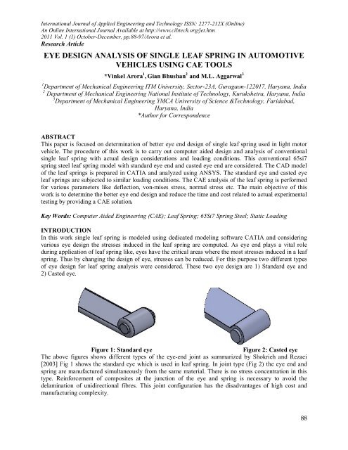
Figure 1: Standard <strong>eye</strong><br />
Figure 2: Casted <strong>eye</strong><br />
The above figures shows different types <strong>of</strong> the <strong>eye</strong>-end jo<strong>in</strong>t as summarized by Shokrieh and Rezaei<br />
[2003] Fig 1 shows the standard <strong>eye</strong> which is used <strong>in</strong> <strong>leaf</strong> <strong>spr<strong>in</strong>g</strong>. In jo<strong>in</strong>t type (Fig 2) the <strong>eye</strong> end and<br />
<strong>spr<strong>in</strong>g</strong> are manufactured simultaneously from the same material. There is no stress concentration <strong>in</strong> this<br />
type. Re<strong>in</strong>forcement <strong>of</strong> composites at the junction <strong>of</strong> the <strong>eye</strong> and <strong>spr<strong>in</strong>g</strong> is necessary to avoid the<br />
delam<strong>in</strong>ation <strong>of</strong> unidirectional fibres. This jo<strong>in</strong>t configuration has the disadvantages <strong>of</strong> high cost and<br />
manufactur<strong>in</strong>g complexity.<br />
88
International Journal <strong>of</strong> Applied Eng<strong>in</strong>eer<strong>in</strong>g and Technology ISSN: 2277-212X (Onl<strong>in</strong>e)<br />
An Onl<strong>in</strong>e International Journal Available at http://www.cibtech.org/jet.htm<br />
2011 Vol. 1 (1) October-December, pp.88-97/Arora et al.<br />
Research Article<br />
Mouleeswaran et al [2007] describes static and fatigue <strong>analysis</strong> <strong>of</strong> steel <strong>leaf</strong> <strong>spr<strong>in</strong>g</strong>s and composite multi<br />
<strong>leaf</strong> <strong>spr<strong>in</strong>g</strong> made up <strong>of</strong> glass fibre re<strong>in</strong>forced polymer us<strong>in</strong>g life data <strong>analysis</strong>. The dimensions <strong>of</strong> exist<strong>in</strong>g<br />
conventional steel <strong>leaf</strong> <strong>spr<strong>in</strong>g</strong>s <strong>of</strong> a light commercial vehicle are taken and are verified by <strong>design</strong><br />
calculations. Static <strong>analysis</strong> <strong>of</strong> 2-D model <strong>of</strong> conventional <strong>leaf</strong> <strong>spr<strong>in</strong>g</strong> is also performed us<strong>in</strong>g ANSYS 7.1<br />
and compared with experimental results. Hawang W et al [1986] Fatigue <strong>of</strong> Composites – Fatigue<br />
Modulus Concept and Life Prediction Journal <strong>of</strong> Composite Materials. H. A. Al-Qureshi [2001] has<br />
described a <strong>s<strong>in</strong>gle</strong> <strong>leaf</strong>, variable thickness <strong>spr<strong>in</strong>g</strong> <strong>of</strong> glassfiber re<strong>in</strong>forced plastic (GFRP) with similar<br />
mechanical and geometrical properties to the multi<strong>leaf</strong> steel <strong>spr<strong>in</strong>g</strong>, was <strong>design</strong>ed, fabricated and tested.<br />
J.J.Fuentes et al [2008] <strong>in</strong> this work, the orig<strong>in</strong> <strong>of</strong> premature failure <strong>analysis</strong> procedures, <strong>in</strong>clud<strong>in</strong>g<br />
exam<strong>in</strong><strong>in</strong>g the <strong>leaf</strong> <strong>spr<strong>in</strong>g</strong> history, visual <strong>in</strong>spection <strong>of</strong> fractured specimens, characterization <strong>of</strong> various<br />
properties and simulation tests on real components, were used. Rajendran I, S. Vijayarangan [2002] A<br />
formulation and solution technique us<strong>in</strong>g genetic algorithms (GA) for <strong>design</strong> optimization <strong>of</strong> composite<br />
<strong>leaf</strong> <strong>spr<strong>in</strong>g</strong>s is presented here. Gulur Siddaramanna et al [2006] expla<strong>in</strong> the automobile <strong>in</strong>dustry has<br />
shown <strong>in</strong>creased <strong>in</strong>terest <strong>in</strong> the replacement <strong>of</strong> steel <strong>spr<strong>in</strong>g</strong> with fiberglass composite <strong>leaf</strong> <strong>spr<strong>in</strong>g</strong> due to<br />
high strength to weight ratio. Leaf <strong>spr<strong>in</strong>g</strong>s <strong>in</strong>dustries work<strong>in</strong>g with 65Si7 <strong>spr<strong>in</strong>g</strong> steel are us<strong>in</strong>g a very low<br />
factor <strong>of</strong> safety for weight reduction. To achieve this, experimental test<strong>in</strong>g is done to predict the <strong>spr<strong>in</strong>g</strong><br />
rate, bend<strong>in</strong>g stress and deflection. Aggarwal M.L et al [2006] evaluated the axial fatigue strength <strong>of</strong><br />
EN45A <strong>spr<strong>in</strong>g</strong> steel specimen experimentally as a function <strong>of</strong> shot peen<strong>in</strong>g <strong>in</strong> the conditions used for fullscale<br />
<strong>leaf</strong> <strong>spr<strong>in</strong>g</strong>s test<strong>in</strong>g <strong>in</strong> <strong>in</strong>dustries. S/N curves <strong>of</strong> the specimens are correlated with <strong>leaf</strong> <strong>spr<strong>in</strong>g</strong>s curve<br />
<strong>in</strong> vehicles. The process is time consum<strong>in</strong>g and costly. In the present work, a CAE system predicts<br />
various variables <strong>in</strong> complex assemblies <strong>of</strong> <strong>leaf</strong> <strong>spr<strong>in</strong>g</strong>s and the results are compared with experimental<br />
test<strong>in</strong>g. J.P. Hou et al [2007] expla<strong>in</strong>ed the <strong>design</strong> evolution process <strong>of</strong> a composite <strong>leaf</strong> <strong>spr<strong>in</strong>g</strong> for freight<br />
rail application.<br />
MATERIALS<br />
The basic requirements <strong>of</strong> <strong>leaf</strong> <strong>spr<strong>in</strong>g</strong>s steel is that the selected grade <strong>of</strong> steel must have sufficient harden<br />
ability for the size <strong>in</strong>volved to ensure a full martenstic structure throughout the entire <strong>leaf</strong> section. In<br />
general terms higher alloy content is mandatory to ensure adequate harden ability when the thick <strong>leaf</strong><br />
sections are used. The material used is 65Si7. The chemical composition <strong>of</strong> the material is shown below<br />
<strong>in</strong> Table 1.<br />
Table 1: Chemical composition <strong>of</strong> 65Si7<br />
GRADE C% Si% Mn % P% S%<br />
65Si7 0.61 0.79 0.014 0.035 0.024<br />
89
International Journal <strong>of</strong> Applied Eng<strong>in</strong>eer<strong>in</strong>g and Technology ISSN: 2277-212X (Onl<strong>in</strong>e)<br />
An Onl<strong>in</strong>e International Journal Available at http://www.cibtech.org/jet.htm<br />
2011 Vol. 1 (1) October-December, pp.88-97/Arora et al.<br />
Research Article<br />
1.1 Design Parameters<br />
The <strong>design</strong> parameters are shown below <strong>in</strong> Table 2.<br />
Table 2: Design parameters<br />
Parameter<br />
Value<br />
Material selected- steel<br />
65Si7<br />
Young’s Modulus, E 2.1x10 5 N/mm 2<br />
HRC 38<br />
Poisson’s Ratio 0.266<br />
Tensile strength Ultimate<br />
Tensile strength Yield<br />
Leaf span<br />
Spr<strong>in</strong>g stiffness<br />
1272 MPa<br />
1158 MPa<br />
1450mm<br />
220 N/mm<br />
Density 0.00000785 Kg/mm 3<br />
2. Model<strong>in</strong>g and Analysis<br />
The 2D draw<strong>in</strong>g <strong>of</strong> <strong>leaf</strong> <strong>spr<strong>in</strong>g</strong>s is shown <strong>in</strong> the Figure 4 below.<br />
Figure 3: Draw<strong>in</strong>g <strong>of</strong> <strong>leaf</strong> <strong>spr<strong>in</strong>g</strong>s<br />
3.1 CAD Model<strong>in</strong>g<br />
CAD model<strong>in</strong>g <strong>of</strong> any project is one <strong>of</strong> the most time consum<strong>in</strong>g process. One cannot shoot directly from<br />
the form sketches to f<strong>in</strong>ite element model. CAD model<strong>in</strong>g is the base <strong>of</strong> any project. The f<strong>in</strong>ite element<br />
s<strong>of</strong>tware will consider shapes, whatever is made <strong>in</strong> CAD model. Although most <strong>of</strong> the CAD model<strong>in</strong>g<br />
s<strong>of</strong>tware have capabilities <strong>of</strong> <strong>analysis</strong> to some extent and most <strong>of</strong> f<strong>in</strong>ite element s<strong>of</strong>tware have capabilities<br />
<strong>of</strong> generat<strong>in</strong>g a CAD model directly for the purpose <strong>of</strong> <strong>analysis</strong>, but their <strong>of</strong>f doma<strong>in</strong> capabilities are not<br />
90
International Journal <strong>of</strong> Applied Eng<strong>in</strong>eer<strong>in</strong>g and Technology ISSN: 2277-212X (Onl<strong>in</strong>e)<br />
An Onl<strong>in</strong>e International Journal Available at http://www.cibtech.org/jet.htm<br />
2011 Vol. 1 (1) October-December, pp.88-97/Arora et al.<br />
Research Article<br />
sufficient for large and complicated models which <strong>in</strong>clude many typical shapes <strong>of</strong> the product. The CAD<br />
models <strong>of</strong> the <strong>eye</strong> <strong>design</strong> were prepared <strong>in</strong> CATIA and the <strong>analysis</strong> and comparison <strong>of</strong> results are<br />
performed us<strong>in</strong>g Ansys. The CAD model <strong>of</strong> the standard <strong>eye</strong> and casted <strong>eye</strong> are shown <strong>in</strong> the Figure<br />
below.<br />
Figure 4: Standard <strong>eye</strong> <strong>design</strong><br />
Figure 5: Casted <strong>eye</strong> <strong>design</strong><br />
3.2 Analysis Us<strong>in</strong>g Ansys<br />
The CAD model <strong>of</strong> <strong>leaf</strong> <strong>spr<strong>in</strong>g</strong>s is now imported <strong>in</strong>to Ansys-11 as shown <strong>in</strong> figures below. All the<br />
boundary conditions and material properties are specified as per the standards used <strong>in</strong> the practical<br />
application. The material used for the <strong>leaf</strong> <strong>spr<strong>in</strong>g</strong> for <strong>analysis</strong> is structural steel, which has approximately<br />
similar isotropic behavior and properties as compared to 65Si7 <strong>spr<strong>in</strong>g</strong> steel <strong>leaf</strong> <strong>spr<strong>in</strong>g</strong>s.<br />
91
International Journal <strong>of</strong> Applied Eng<strong>in</strong>eer<strong>in</strong>g and Technology ISSN: 2277-212X (Onl<strong>in</strong>e)<br />
An Onl<strong>in</strong>e International Journal Available at http://www.cibtech.org/jet.htm<br />
2011 Vol. 1 (1) October-December, pp.88-97/Arora et al.<br />
Research Article<br />
Figure 6: Standard <strong>eye</strong> <strong>in</strong> Ansys<br />
Figure 7: Standard <strong>eye</strong> <strong>in</strong> Ansys<br />
The procedure for perform<strong>in</strong>g <strong>analysis</strong> <strong>in</strong> ANSYS <strong>in</strong>volves:<br />
3.2.1 Specify<strong>in</strong>g Jo<strong>in</strong>ts<br />
A jo<strong>in</strong>t is an idealized k<strong>in</strong>ematics l<strong>in</strong>kage that controls the relative movement between two bodies. Jo<strong>in</strong>t<br />
types are characterized by their rotational and translational degrees <strong>of</strong> freedom as be<strong>in</strong>g fixed or free. In<br />
this assembly two revolute jo<strong>in</strong>ts are used between <strong>eye</strong> and p<strong>in</strong>. The jo<strong>in</strong>t rotation is 18˚ correspond<strong>in</strong>g to<br />
no load camber angle <strong>of</strong> 162º.<br />
Figure 8: Revolute jo<strong>in</strong>t between <strong>eye</strong> and p<strong>in</strong><br />
3.2.2. Mesh<strong>in</strong>g<br />
Mesh<strong>in</strong>g is the process <strong>in</strong> which your geometry is spatially discretized <strong>in</strong>to elements and nodes. This<br />
mesh along with material properties is used to mathematically represent the stiffness and mass<br />
distribution <strong>of</strong> your structure. The default element size is determ<strong>in</strong>ed based on a number <strong>of</strong> factors<br />
<strong>in</strong>clud<strong>in</strong>g the overall model size, the proximity <strong>of</strong> other topologies, body curvature, and the complexity <strong>of</strong><br />
the feature. If necessary, the f<strong>in</strong>eness <strong>of</strong> the mesh is adjusted up to four times (eight times for an<br />
assembly) to achieve a successful mesh. In this assembly SOLID92 mesh element is used for the results.<br />
92
International Journal <strong>of</strong> Applied Eng<strong>in</strong>eer<strong>in</strong>g and Technology ISSN: 2277-212X (Onl<strong>in</strong>e)<br />
An Onl<strong>in</strong>e International Journal Available at http://www.cibtech.org/jet.htm<br />
2011 Vol. 1 (1) October-December, pp.88-97/Arora et al.<br />
Research Article<br />
Figure 9: Meshed model <strong>of</strong> standard <strong>eye</strong> <strong>leaf</strong><br />
Figure 10: Meshed model <strong>of</strong> casted <strong>eye</strong> <strong>leaf</strong><br />
3.2.3. Sett<strong>in</strong>g Analysis Environment<br />
A static structural <strong>analysis</strong> determ<strong>in</strong>es the displacements, stresses, stra<strong>in</strong>s, and forces <strong>in</strong> structures or<br />
components caused by loads that do not <strong>in</strong>duce significant <strong>in</strong>ertia and damp<strong>in</strong>g effects. Steady load<strong>in</strong>g<br />
and response conditions are assumed; that is, the loads and the structure's response are assumed to vary<br />
slowly with respect to time. Static structure <strong>analysis</strong> takes <strong>in</strong>to consideration some parameters, like<br />
material properties, load<strong>in</strong>g conditions, support conditions, jo<strong>in</strong>ts and contacts which are to be specified<br />
as the <strong>in</strong>put to the pre process<strong>in</strong>g <strong>of</strong> the <strong>analysis</strong>.<br />
3.2.5. Sett<strong>in</strong>g Boundary Conditions<br />
The boundary conditions are applied by tak<strong>in</strong>g <strong>in</strong>to consideration the experimental load<strong>in</strong>g conditions.<br />
The static load<strong>in</strong>g condition <strong>of</strong> <strong>s<strong>in</strong>gle</strong> <strong>leaf</strong> <strong>spr<strong>in</strong>g</strong> <strong>in</strong>volves the fixation <strong>of</strong> one <strong>of</strong> the revolute jo<strong>in</strong>t and<br />
apply<strong>in</strong>g displacement support at the other end <strong>of</strong> <strong>leaf</strong> <strong>spr<strong>in</strong>g</strong>s. Load<strong>in</strong>g conditions <strong>in</strong>volves apply<strong>in</strong>g a<br />
load at the centre <strong>of</strong> the ma<strong>in</strong> <strong>leaf</strong>. As per specifications the <strong>spr<strong>in</strong>g</strong>s is drawn at flat condition, therefore<br />
the load is applied <strong>in</strong> downward direction to achieve <strong>in</strong>itial no load condition. As no load assembly<br />
camber is 162°.<br />
Figure 11: Static load<strong>in</strong>g condition<br />
93
International Journal <strong>of</strong> Applied Eng<strong>in</strong>eer<strong>in</strong>g and Technology ISSN: 2277-212X (Onl<strong>in</strong>e)<br />
An Onl<strong>in</strong>e International Journal Available at http://www.cibtech.org/jet.htm<br />
2011 Vol. 1 (1) October-December, pp.88-97/Arora et al.<br />
Research Article<br />
4.0 Solution<br />
Figure 12: Boundary condition <strong>in</strong> ANSYS<br />
4.1 Results for standard <strong>eye</strong><br />
Figure 13: Total deformation<br />
Figure 14: Normal stress<br />
Figure 15: Von –Mises stress<br />
Figure 16: Factor <strong>of</strong> safety<br />
94
International Journal <strong>of</strong> Applied Eng<strong>in</strong>eer<strong>in</strong>g and Technology ISSN: 2277-212X (Onl<strong>in</strong>e)<br />
An Onl<strong>in</strong>e International Journal Available at http://www.cibtech.org/jet.htm<br />
2011 Vol. 1 (1) October-December, pp.88-97/Arora et al.<br />
Research Article<br />
4.2 Results for casted <strong>eye</strong><br />
Figure 17: Total deformation<br />
Figure 18: Normal stress<br />
Figure 19: Von –Mises stress<br />
Figure 20: Factor <strong>of</strong> safety<br />
RESULTS AND DISCUSSION<br />
Table 3: Result Comparison<br />
Parameter Standard Eye Casted Eye Variation<br />
Load 50 N 50 N Nil<br />
Deflection 109.62 mm 115.61 mm 5.4%<br />
Von Mises Stress 773.34MPa 750.08MPa 3.0%<br />
Normal Stress 654.12MPa 783.51MPa 19.08%<br />
Maximum-15 Maximum-15 Nil<br />
Factor <strong>of</strong> Safety<br />
M<strong>in</strong>imum-0.381 M<strong>in</strong>imum-0.331 13.1%<br />
a. From the above table it is observed that for same static load application, when the standard <strong>eye</strong> is<br />
replaced with casted <strong>eye</strong>, equivalent stress reduction <strong>of</strong> 2.9% and <strong>in</strong>crease <strong>in</strong> deflection <strong>of</strong> 5.44% is<br />
achieved.<br />
b. From the above table it is observed that the m<strong>in</strong>imum value <strong>of</strong> factor <strong>of</strong> safety is reduced by 13.1% for<br />
casted <strong>eye</strong>.<br />
c. It is also observed that there is <strong>in</strong>crease <strong>in</strong> Normal stress by 19.08% <strong>in</strong> the case <strong>of</strong> casted <strong>eye</strong>.<br />
95
International Journal <strong>of</strong> Applied Eng<strong>in</strong>eer<strong>in</strong>g and Technology ISSN: 2277-212X (Onl<strong>in</strong>e)<br />
An Onl<strong>in</strong>e International Journal Available at http://www.cibtech.org/jet.htm<br />
2011 Vol. 1 (1) October-December, pp.88-97/Arora et al.<br />
Research Article<br />
Conclusion<br />
This work <strong>in</strong>volves <strong>design</strong> and <strong>analysis</strong> <strong>of</strong> <strong>s<strong>in</strong>gle</strong> <strong>leaf</strong> <strong>spr<strong>in</strong>g</strong> under static load<strong>in</strong>g conditions. The 3D<br />
model is prepared <strong>in</strong> CATIA and then CAE <strong>analysis</strong> is performed us<strong>in</strong>g ANSYS-11. From the results<br />
obta<strong>in</strong>ed from ANSYS, discussions have been made and it will be concluded that:<br />
1. When same load is applied to standard and casted <strong>leaf</strong> <strong>spr<strong>in</strong>g</strong> equivalent stress reduction <strong>of</strong> 2.9% and<br />
<strong>in</strong>crease <strong>in</strong> deflection <strong>of</strong> 5.44% is achieved. As maximum stress <strong>in</strong>duced is below the yield stress<br />
therefore it is concluded that casted <strong>eye</strong> is also safe under given load<strong>in</strong>g conditions.<br />
2. At the same time bend<strong>in</strong>g stress for same load is <strong>in</strong>creased by 19.08 % <strong>in</strong> case <strong>of</strong> casted <strong>eye</strong> <strong>analysis</strong> as<br />
compared with standard <strong>eye</strong>. This may be observed because the actual material is 65Si7 but for CAE<br />
<strong>analysis</strong> structural steel is used.<br />
3. As the m<strong>in</strong>imum factor <strong>of</strong> safety is reduced by 13.1% <strong>in</strong> case <strong>of</strong> casted <strong>eye</strong> it is concluded that the area<br />
<strong>of</strong> m<strong>in</strong>imum factor <strong>of</strong> safety will fail earlier <strong>in</strong> case <strong>of</strong> casted <strong>eye</strong>. Hence casted <strong>eye</strong> is not<br />
recommended.<br />
4. It is concluded that CAE tools provides a cost effective and less time consum<strong>in</strong>g solution <strong>in</strong> comparison<br />
with the experimental test<strong>in</strong>g but the results may vary <strong>in</strong> the specified range.<br />
ACKNOWLEDGEMENT<br />
At the very last, I would like to acknowledge Friends Auto <strong>in</strong>dustries, Faridabad and their <strong>leaf</strong> <strong>spr<strong>in</strong>g</strong><br />
test<strong>in</strong>g division for their constant support and guidance.<br />
REFERENCES<br />
Aggarwal ML and Khan RA ( 2006). A stress approach model for predict<strong>in</strong>g fatigue life <strong>of</strong> shot peened<br />
EN45A <strong>spr<strong>in</strong>g</strong> steel. International Journal <strong>of</strong> Fatigue (Elsevier Publication) 28 1845-1853.<br />
Gulur Siddaramanna, Shiva shanker and Sambagam Vijayaragan (2006). Mono Composite Leaf<br />
<strong>spr<strong>in</strong>g</strong> for light weight vehicle ‘Design, end Jo<strong>in</strong>t <strong>analysis</strong> and test<strong>in</strong>g’. Materials Science 12(3) 220-225.<br />
Hawang W and Han KS (1986). Fatigue <strong>of</strong> Composites – “Fatigue Modulus Concept and Life<br />
Prediction. Journal <strong>of</strong> Composite Materials 20 154 – 165.<br />
HA Al-Qureshi (2001). Automobile <strong>leaf</strong> <strong>spr<strong>in</strong>g</strong>s from composite materials. Journal <strong>of</strong> Material<br />
Process<strong>in</strong>g Technology 118 58-61.<br />
I Rajendran and S Vijayarangan (2002). Design and Analysis <strong>of</strong> a Composite Leaf Spr<strong>in</strong>g. Journal <strong>of</strong><br />
Institute <strong>of</strong> Eng<strong>in</strong>eers India 82 180 –187.<br />
JJ Fuentes, HJ Agulilar, JA Rodriguez and EJ Herrera (2008). Premature fracture <strong>in</strong> automobile <strong>leaf</strong><br />
<strong>spr<strong>in</strong>g</strong>s. Eng<strong>in</strong>eer<strong>in</strong>g Failure Analysis 16 648-655.<br />
MM Patunkar and DR Dolas (2011). Modell<strong>in</strong>g and Analysis <strong>of</strong> composite <strong>leaf</strong> <strong>spr<strong>in</strong>g</strong> under the static<br />
load condition by us<strong>in</strong>g FEA. International Journal <strong>of</strong> Mechanical & Industrial Eng<strong>in</strong>eer<strong>in</strong>g 1 1-2011<br />
pp. 1-4.<br />
Mouleeswaran Senthil Kumar and Sabapathy Vijayarangan (2007). Analytical and experimental<br />
studies on fatigue life prediction <strong>of</strong> steel and composite multi-<strong>leaf</strong> <strong>spr<strong>in</strong>g</strong> for light passenger vehicles<br />
us<strong>in</strong>g life data <strong>analysis</strong>. Materials Science 13(2) 141-146.<br />
Supavut Chantranuwathana, Kadekheaw Panichanun, Preedanood Prempreeda, Pimply Wichien<br />
prakarn and Parig Kruo-ongarjnukool (2009). Experimental verification <strong>of</strong> <strong>leaf</strong> <strong>spr<strong>in</strong>g</strong> model by<br />
us<strong>in</strong>g a <strong>leaf</strong> <strong>spr<strong>in</strong>g</strong> test rig. 23rd Conference <strong>of</strong> Mechanical Eng<strong>in</strong>eer<strong>in</strong>g Network <strong>of</strong> Thailand 123-131.<br />
Shokrieh MM and Rezaei D (2003). Analysis and Optimisation <strong>of</strong> composite <strong>leaf</strong> <strong>spr<strong>in</strong>g</strong>. Composite<br />
Structures 60 317-325.<br />
96
International Journal <strong>of</strong> Applied Eng<strong>in</strong>eer<strong>in</strong>g and Technology ISSN: 2277-212X (Onl<strong>in</strong>e)<br />
An Onl<strong>in</strong>e International Journal Available at http://www.cibtech.org/jet.htm<br />
2011 Vol. 1 (1) October-December, pp.88-97/Arora et al.<br />
Research Article<br />
RM Mayer, JP Hou, JY Cherruault, I Nairne and G Jeronimidis (2007). Evolution <strong>of</strong> the <strong>eye</strong>-end<br />
<strong>design</strong> <strong>of</strong> a composite <strong>leaf</strong> <strong>spr<strong>in</strong>g</strong> for heavy axle loads. Composite Structures 64 351-358<br />
Peiyong Q<strong>in</strong>, Glenn Dentel and Mikhail Mesh (2002). Multi-Leaf Spr<strong>in</strong>g and Hotchkiss Suspension.<br />
ABAQUS Users’ Conference.<br />
97


