Application Note: Using Modems with Sound Level Meters (BO0458 ...
Application Note: Using Modems with Sound Level Meters (BO0458 ...
Application Note: Using Modems with Sound Level Meters (BO0458 ...

Create successful ePaper yourself
Turn your PDF publications into a flip-book with our unique Google optimized e-Paper software.
APPLICATION NOTE<br />
<strong>Using</strong> <strong>Modems</strong> <strong>with</strong> <strong>Sound</strong> <strong>Level</strong> <strong>Meters</strong><br />
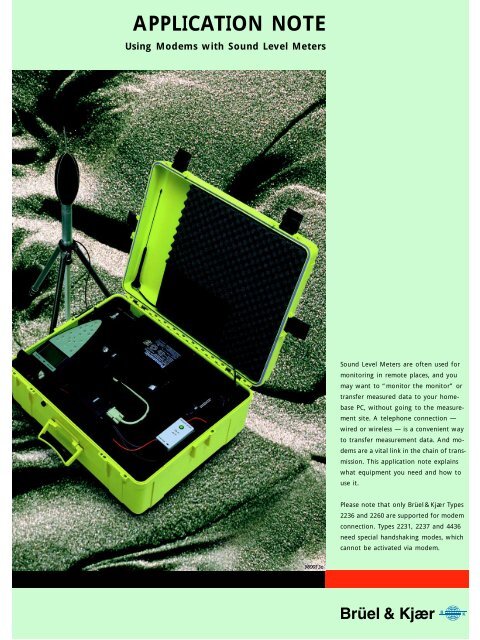
<strong>Sound</strong> <strong>Level</strong> <strong>Meters</strong> are often used for<br />
monitoring in remote places, and you<br />
may want to “monitor the monitor” or<br />
transfer measured data to your homebase<br />
PC, <strong>with</strong>out going to the measurement<br />
site. A telephone connection —<br />
wired or wireless — is a convenient way<br />
to transfer measurement data. And modems<br />
are a vital link in the chain of transmission.<br />
This application note explains<br />
what equipment you need and how to<br />
use it.<br />
Please note that only Brüel& Kjær Types<br />
2236 and 2260 are supported for modem<br />
connection. Types 2231, 2237 and 4436<br />
need special handshaking modes, which<br />
cannot be activated via modem.
<strong>Using</strong> <strong>Modems</strong> <strong>with</strong> <strong>Sound</strong> <strong>Level</strong> <strong>Meters</strong><br />
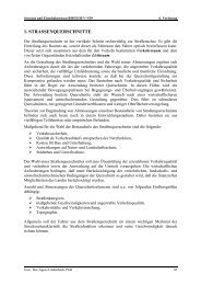
Fig. 1 2260 Semi-permanent Monitoring<br />
System<br />
2260 Semi-permanent Monitoring Kit<br />
A sound level meter for monitoring in the field needs protection against<br />
weather and tampering, and it needs a power supply other than its<br />
internal batteries. Also, you need space and power for the modem.<br />
For the Investigator <strong>Sound</strong> <strong>Level</strong> Analyzer Type 2260, the 2260 Semipermanent<br />
Monitoring Kit is available. It includes a weatherproof case,<br />
12 V battery, battery charger, cables, Outdoor Microphone Kit and software<br />
for Type 2260 and for the PC. The case has room for all the<br />
equipment including a modem, and it has a cable entry for feeding<br />
external power to the system. A complete system including the 2260 is<br />
also available: the 2260 Semi-permanent Monitoring System has all the<br />
equipment in the Kit, plus the 2260, a calibrator, a tripod and an interface<br />
cable for a PC. For ordering information, see the “Noise Monitoring”<br />
System Summary sheet (BU 3063).<br />
2
Standard <strong>Modems</strong><br />
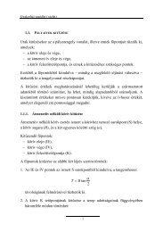
This section shows how to capture sound measurements from a remote<br />
<strong>Sound</strong> <strong>Level</strong> Analyzer (Investigator Type 2260) via telephone lines and<br />
standard modems. Precision Integrating <strong>Sound</strong> <strong>Level</strong> Meter Type 2236<br />
may also be used.<br />
The field equipment is illustrated in Fig. 2.<br />
Fig. 2 Field equipment shown <strong>with</strong><br />
standard modem. The telephone line<br />
connector is shown in the lid<br />
3
TOSHIBA<br />
dflkfpojmmljflkjgjrg<br />
grmowjgfpktjpw<br />
dB<br />
0<br />
<br />
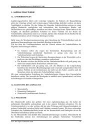
Fig. 3 Standard modem set-up<br />
PC running<br />
Evaluator<br />
Type 7820<br />
Hayes ¤ Compatible<br />
Modem<br />
B&K 2236<br />
or 2260<br />
Dumb Auto<br />
Answer Modem<br />
(Multitech MT 2834ZDX)<br />
980001e<br />
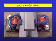
Fig. 4 shows the complete system including the home-base modem.<br />
Fig. 4 System diagram. The diagram<br />
does not include the optional DAT recorder<br />
Mains Power<br />
Outdoor Microphone Kit UA 1404<br />
(Preamplifier ZG 0026 and<br />
Microphone 4189, from 2260)<br />
Microphone Extension Cable<br />
AO 0441 (3m)<br />
AO 0442 (10m)<br />
Lightweight<br />
Tripod<br />
UA 0801<br />
Tripod<br />
UA 0587<br />
<strong>Sound</strong> <strong>Level</strong> Analyzer<br />
Type 2260<br />
+ –<br />
Mains Power Supply<br />
ZG 0386 (EU)<br />
ZG 0387 (UK)<br />
ZG 0388 (US)<br />
Brüel & Kjær Type 2260<br />
Cable for<br />
12V Supply<br />
Mains Adaptor<br />
(included <strong>with</strong><br />
Multitech Modem)<br />
MT2834ZDX<br />
Field modem<br />
Multitech<br />
Panasonic<br />
12V Battery<br />
QB 0051<br />
Battery Charger<br />
ZG 0404<br />
Case Type 3592<br />
<strong>Sound</strong> <strong>Level</strong><br />
Calibrator 4231<br />
Home-base Modem<br />
Hayes ® compatible<br />
Evaluator 7820<br />
Community noise<br />
calculations<br />
<strong>Note</strong>book/PC<br />
Telephone<br />
system<br />
970551e<br />
Standard <strong>Modems</strong> — Field Modem<br />
The modem used in the field must be intelligent enough to provide<br />
error correction, but dumb enough not to interpret any of the communication<br />
nor to add anything by sending messages to the sound level<br />
meter (see APPENDIX 1: Selection of Field Modem).<br />
Testing a number of modems, Brüel & Kjær has found the Multitech<br />
MT2834ZDX to be the best choice, and recommends only that for field<br />
use.<br />
Brüel & Kjær does not provide technical support for other modems.<br />
4
Table1 Equipment Equipment Type Available From<br />
PC operating system Windows 95 ® ,<br />
Windows NT4.0 ® ,<br />
Windows ® 3.10 or 3.11<br />
PC supplier<br />
PC-modem cable Depends on modem and PC Modem or PC<br />
supplier<br />
Home-base modem<br />
Hayes ® compatible<br />
e.g. Multitech MT2834ZDX<br />
Modem supplier or<br />
Brüel & Kjær<br />
(ZM 0069)<br />
Field modem Multitech MT2834ZDX Modem supplier or<br />
Brüel & Kjær<br />
(ZM 0069)<br />
Modem power<br />
Mains adaptor (supplied) or<br />
9VDC<br />
Brüel & Kjær<br />
SLM-modem cable AO 0567 Brüel & Kjær<br />
SLM 2260 (or 2236) Brüel & Kjær<br />
SLM power<br />
2260 Semipermanent<br />
Monitoring Kit<br />
Lightweight Tripod<br />
Tripod<br />
12 V DC from QB 0051 or<br />
Mains Power Supply<br />
ZG 0386 (EU)<br />
ZG 0387 (UK)<br />
ZG 0388 (US)<br />
BZ 7202–302 (English)<br />
BZ 7202–303 (French)<br />
BZ 7202–304 (German)<br />
BZ 7202 Enhanced <strong>Sound</strong><br />
Analysis SW<br />
3592 Outdoor Gear<br />
UA 1404 Outdoor Microphone<br />
Kit<br />
AO 0441 Microphone<br />
Extension Cable (3 m)<br />
QB 0051 12 V Battery<br />
AQ 1698 Cable for 12 V Supply<br />
ZG 0404 Battery Charger<br />
AQ 1700 Cable for DAT Remote<br />
AO 0543 DAT Signal Cable<br />
7820 – 002 Evaluator (English)<br />
7820– 003 Evaluator (French)<br />
7820– 004 Evaluator (German)<br />
UA 0801<br />
UA 0587<br />
Brüel & Kjær<br />
Brüel & Kjær<br />
Brüel & Kjær<br />
<strong>Sound</strong> <strong>Level</strong><br />
Calibrator<br />
4231 Brüel & Kjær<br />
Setting up the Field Modem<br />
The Multitech modem is configured from the factory to be used as a<br />
Hayes ® compatible modem together <strong>with</strong> your PC. In order to get this<br />
modem to work in the field you must do some programming of the<br />
modem.<br />
Begin by connecting the Multitech modem to COM1 or COM2 on your<br />
PC, then start the Evaluator application. Choose Options… on the Tools<br />
menu. Next select the Modem tab. On the modem droplist select User<br />
Defined Modem, then set the actual COM-port where you have connected<br />
the Multitech modem. Finally set the Baud Rate to 19200.<br />
5
Click on the Test the connection… button to launch the Serial Communications<br />
Tool.<br />
If your modem is properly connected to the PC, all the status indicators<br />
except DCD should show ✓. To verify that the modem is recognized<br />
enter the letters A and T in the String to be transmitted box and click<br />
on the Enter button. The modem should then reply OK.<br />
If your modem has reacted as described above, you can go on <strong>with</strong> the<br />
programming of the modem. Enter the commands one bye one from<br />
Table2 into the String to be transmitted box and click on the Enter<br />
button after each command:<br />
All 0 characters on the list are zeros. Please note that this list of commands<br />
is only valid for the Multitech modem. It is not guaranteed to<br />
work <strong>with</strong> other types of modems.<br />
Now the Multitech modem can be connected to the SLM in the field.<br />
Use cable AO 0567 which is a straightforward extension cable (male/<br />
6
Table2<br />
modem<br />
Commands for the Multitech<br />
ATM0<br />
Enter command<br />
Significance<br />
Speaker off<br />
ATE0<br />
No Echo<br />
AT%E0<br />
No Escape Sequence<br />
ATS0=1<br />
Answer incoming calls after first ring<br />
AT$SB19200<br />
ATQ1<br />
AT&W0<br />
Lock the baud rate to the SLM to<br />
19200 bits/sec<br />
No Result codes<br />
Write the new configuration to the<br />
modem non volatile memory<br />
female 25-pin/9-pin cable <strong>with</strong> all lines in 1–1 connection) — Do not use<br />
the Brüel & Kjær AO 1386 cable in this case!<br />
Setting up the 2236 for Modem Transfer<br />
1. Press the button 9 times until the display shows INTERFACE.<br />
2. Press the button.<br />
3. Press the or button until the display shows<br />
19200 Baud.<br />
4. Press the or button.<br />
5. Press the or button until the display shows<br />
Hardwire.<br />
6. Press the button twice.<br />
Now your 2236 has the right communication set-up and you can continue<br />
to set up the measuring parameters. As the Evaluator can only<br />
remote control 2236 to start and stop measurements via the Autolog to<br />
log command, you must start the initial log by specifying the sampling<br />
interval, for example, Autolog to log every 1 min.<br />
Setting up the 2260 for Modem Transfer<br />
1. Press the button to enter the Setup screen.<br />
2. Press the softkey.<br />
3. Use the ❒ soft key to move down and select PC communication.<br />
4. Set the baud rate to 19200.<br />
5. Press .<br />
After having programmed the communication parameters you must select<br />
the desired measurement set-up. Please refer to your 2260 User<br />
Manual for information.<br />
Standard <strong>Modems</strong> — Home-base Modem<br />
Most modems available for use <strong>with</strong> a PC will do well for the homebase<br />
modem. It must fulfil the following requirements:<br />
❍ It must be Hayes compatible (supporting the AT command set)<br />
❍ The DCD (Data Carrier Detect) line must indicate the actual connection<br />
state<br />
❍ The modem must disconnect whenever the DTR (Data Terminal<br />
Ready) line goes false<br />
❍ The modem must provide correction of transmission errors<br />
7
Setting up the Home-base Modem<br />
After connecting the modem to your PC using the modem-PC cable, you<br />
can configure the PC software. If you use Windows 95 or<br />
Windows NT4.0, you must install the modem via the control panel in<br />
Windows first.<br />
Start the Evaluator Type 7820. Choose Options… on the Tools menu.<br />
Next select the Modem tab. Again if you use Windows 95 or NT4.0, your<br />
modem is already known by the system, so all you have to do is select<br />
it on the drop-down list.<br />
If you want to test the connection to the modem, you can click on the<br />
Test the connection… button, whereby you launch the Serial Communications<br />
Debugging Tool. On this screen you can test the modem connection<br />
by selecting the Test Modem in the Function box in the lower right<br />
corner.<br />
If you use Windows 3.10 or 3.11 or if you have problems getting your<br />
modem to work under Windows 95/NT4.0 you should create a User<br />
defined modem set-up in Evaluator:<br />
8
Select the COM-port and Baud Rate. In the INIT command and in the<br />
DIAL command you can insert any string that the software should send<br />
to the modem during initialization and dialing. Start by putting ATZ in<br />
the init command and ATDT in the dial command. If more than one<br />
command is needed for initialization just put (4 letters) in as<br />
separator, for example:<br />
ATATZATM0<br />
Please consult your modem manual for details on the command parameters.<br />
Setting up the Telephone Numbers for Dial-up Sites<br />
Evaluator has a built-in database for keeping phone numbers for remote<br />
sound level meters, that will be contacted by the modem connection.<br />
This database can contain any number of sites.<br />
To define new Dial-up Sites, Choose Options… on the Tools menu. Next<br />
select the Dial-up Sites tab. Then click on the New Site… button. Enter<br />
the name of the new site — any characters except \ are allowed in the<br />
site name.<br />
Then enter the telephone number. The Dial prefix box can be used to<br />
add extra dialing parameters, for example, to get a line outside a local<br />
phone system. If your system requires that you dial, for example, a 0<br />
to get an outside line, then put 0 in the dial prefix box, otherwise leave<br />
this box blank.<br />
Continue this process until all sites have been defined in the database.<br />
Dialling a Remote Site<br />
When your field system has been set up and your home-base modem<br />
has been connected to your PC, you can start downloading measurement<br />
data from the field.<br />
This is done the same way that you would capture data from a SLM in<br />
direct connection <strong>with</strong> a PC, except that you put a ✓ in the box called<br />
Connect via modem (Dial-up). When the ✓ is set in the box, the screen<br />
will change and you will be asked to choose which remote site to dial.<br />
9
Once the PC has connection to the remote site, the rest of the download<br />
process is the same as if the SLM was connected to your PC via the<br />
AO 1386 cable.<br />
Wireless Modem<br />
<strong>Using</strong> a GSM dataphone, your field system becomes truly mobile and<br />
wireless — no power line and no phone line is required. There is an<br />
extra team player in the communication chain: the GSM network operator.<br />
But once you have got the settings right, it works as smoothly as<br />
the data transfer via normal telephone lines.<br />
This section shows how to capture sound measurements from a remote<br />
sound level analyzer (Investigator Type 2260) via GSM transmission in<br />
the field and standard telephone lines and modems at the home-base.<br />
(Precision Integrating <strong>Sound</strong> <strong>Level</strong> Meter Type 2236 may also be used).<br />
The field equipment is illustrated in Fig. 5.<br />
Fig. 5 Field equipment shown <strong>with</strong> wireless<br />
modem. The antenna must be<br />
placed to the right in the foam insert,<br />
before the lid is closed<br />
Field Equipment<br />
Fig. 6 shows the complete system including the home-base modem.<br />
10
TOSHIBA<br />
5MB<br />
FLASHDISK<br />
MAGS STORAGE<br />
SYSTEM<br />
Sun isk<br />
dflkfpojmmljflkjgjrg<br />
grmowjgfpktjpw<br />
dB<br />
0<br />
<br />
Handswitch ZH 0631<br />
Off<br />
On<br />
B7/6-’89<br />
K<br />
Br el &Kjr<br />
Fig. 6 System diagram. The diagram<br />
does not include the optional DAT<br />
recorder<br />
Case Type 3592<br />
Outdoor Microphone Kit UA 1404<br />
(Preamplifier ZG 0026 and <strong>Sound</strong> <strong>Level</strong> Analyzer<br />
Microphone 4189, from 2260) Type 2260<br />
Microphone Extension Cable<br />
AO 0441 (3m)<br />
AO 0442 (10m)<br />
Lightweight<br />
Tripod<br />
UA 0801<br />
Tripod<br />
UA 0587<br />
Enhanced <strong>Sound</strong><br />
Analysis Software<br />
BZ 7202<br />
+ —<br />
Br el & Kj r Type 2260<br />
Cable for<br />
12V Supply<br />
Field Modem<br />
Siemens M1<br />
SIM<br />
Card<br />
Modem Handswitch<br />
ZH 0457<br />
GSM<br />
Antenna<br />
Panasonic<br />
12V Battery<br />
QB 0051<br />
Battery Charger<br />
ZG 0404<br />
<strong>Sound</strong> <strong>Level</strong><br />
Calibrator 4231<br />
Evaluator 7820<br />
Community noise<br />
calculations<br />
<strong>Note</strong>book/PC<br />
Home-base Modem<br />
Hayes ¤ compatible<br />
Telephone<br />
system<br />
GSM<br />
network<br />
970556e<br />
Fig. 7 Wireless modem set-up<br />
PC running<br />
Evaluator<br />
Type 7820<br />
Hayes ® Compatible<br />
Modem<br />
Brüel & Kjær 2236<br />
or 2260<br />
Siemens Mobile<br />
Dataphone M1<br />
Modem at<br />
GSM Operator<br />
GSM Net<br />
Operator<br />
970560e<br />
2260 Semi-permanent Monitoring Kit<br />
Please refer to the description in the Standard Modem section.<br />
11
Table3 Equipment Equipment Type Available From<br />
PC operating system Windows 95<br />
Windows NT4.0<br />
Windows 3.10 or 3.11<br />
PC supplier<br />
PC-modem cable Depends on modem and PC Modem or PC<br />
supplier<br />
Home-base modem<br />
Field modem<br />
GSM SIM Card<br />
Hayes compatible<br />
e.g. Multitech MT2834ZDX<br />
Siemens Mobile Dataphone<br />
M1<br />
For non-transparent data<br />
transfer<br />
Modem supplier<br />
or Brüel & Kjær<br />
(ZM 0069)<br />
Siemens supplier<br />
Network operator<br />
Modem Handswitch ZH 0457 Brüel & Kjær<br />
Antenna + mounting See section “Antenna” below Mobile-phone<br />
supplier<br />
SLM-Modem cable AO 1440 Brüel & Kjær<br />
SLM 2260 (or 2236) Brüel & Kjær<br />
2260 Semi-permanent<br />
Monitoring Kit<br />
Lightweight Tripod<br />
Tripod<br />
BZ 7202 – 302 (English)<br />
BZ 7202 – 303 (French)<br />
BZ 7202 – 304 (German)<br />
BZ 7202 Enhanced <strong>Sound</strong><br />
Analysis SW<br />
3592 Outdoor Gear<br />
UA 1404 Outdoor Microphone<br />
Kit<br />
AO 0441 Microphone<br />
Extension Cable (3 m)<br />
QB 0051 12 V Battery<br />
AQ 1698 Cable for 12 V Supply<br />
ZG 0404 Battery Charger<br />
AQ 1700 Cable for DAT<br />
Remote<br />
AO 0543 DAT Signal Cable<br />
7820 – 002 Evaluator (English)<br />
7820 – 003 Evaluator (French)<br />
7820 – 004 Evaluator (German)<br />
UA 0801<br />
UA 0587<br />
Brüel & Kjær<br />
Brüel & Kjær<br />
<strong>Sound</strong> <strong>Level</strong> Calibrator 4231 Brüel & Kjær<br />
12
Wireless <strong>Modems</strong> — Siemens M1 Mobile Dataphone<br />
Fig. 8 Siemens M1 Mobile Dataphone<br />
Table4 Siemens M1 Mobile Dataphone<br />
– manufacturer’s specifications<br />
At the field end we need a device<br />
which is a combination of a mobile<br />
phone and a modem. A suitable<br />
device is the Siemens M1 —<br />
it runs on 12 V external DC supply,<br />
and it has a 9–pin RS–232 interface<br />
to the built-in modem which<br />
“talks” directly to the built-in GSM<br />
phone unit. It includes a split cable<br />
for power supply and antenna<br />
connection.<br />
Currently the maximum transfer<br />
rate of this system is 9600 bits/<br />
sec set by the network operator.<br />
In the future the transfer rate may<br />
increase to 19200 bits/sec (which<br />
the M1 is designed for).<br />
Type M1 Nominal voltage 13.2 V<br />
Housing Plastic Input current Max. 500 mA<br />
Dimensions 116 x 67 x 30 mm Class of<br />
protection<br />
III<br />
Weight 157 g Temperature,<br />
operating<br />
Memory Flash EPROM Temperature,<br />
storage<br />
Input voltage +8 to +24V Antenna<br />
impedance<br />
–20 to +55°C<br />
–40 to +70°C<br />
50 Ω<br />
Setting up the GSM System<br />
SIM Card<br />
First of all you must have a GSM SIM card in order to get access to the<br />
GSM network. Make sure that this SIM card is set up to work <strong>with</strong> NON-<br />
TRANSPARENT DATA TRANSFER by your network operator. <strong>Note</strong> that<br />
the phone number for data transfer may not be the same as the phone<br />
number normally used <strong>with</strong> this SIM card. Secondly the SIM card must<br />
not require that a PIN code be entered before use.<br />
Siemens M1<br />
When ordering the Siemens M1, make sure it supports NON-TRANSPAR-<br />
ENT data transfer. This means that the M1 firmware must be version<br />
4.02 or later. See APPENDIX 2: Software Update for Siemens M1, for<br />
details.<br />
Next the M1 should be programmed for autoanswer mode. To do this<br />
connect it to your PC on COM-1 or COM-2 and start the Evaluator<br />
software. Choose Options… from the Tools menu. Then select the Modem<br />
tab.<br />
From the modem droplist select User Defined Modem. Set the actual<br />
COM-port where you have connected the M1. Finally set the Baud Rate<br />
to 9600.<br />
13
Then click on the Test the connection… button.<br />
By entering AT and clicking on the Enter button the M1 should answer<br />
OK.<br />
The command AT+CSQ indicates the signal quality (a number between<br />
0 and 31, where 31 is the best).<br />
The command AT+COPS shows whether you have been registered on<br />
the network or not. It should reply <strong>with</strong> the name of your network<br />
operator.<br />
Now the M1 should be programmed to be in auto-answer mode <strong>with</strong> a<br />
non-transparent error correction protocol and the result codes should<br />
be disabled.<br />
Enter the commands from Table5 , one by one.<br />
After finishing programming you will notice that the M1 no longer indicates<br />
OK to every command, that is because the ATQ1 command has<br />
disabled the output of the results codes. Result codes must be disabled,<br />
otherwise 2260 will try to interpret these messages.<br />
14
Table5 Siemens M1 programming<br />
commands<br />
ATS0=1<br />
Enter Command<br />
Significance<br />
Answer after 1st ring<br />
AT\N6<br />
Operating mode: Non-Transparent,<br />
<strong>with</strong> RLP protocol<br />
ATB98<br />
Operating mode: Autobauding<br />
Modem, 9600 Baud<br />
ATQ1<br />
No Result codes<br />
AT&Y0<br />
Load User Profile 0 at power-up<br />
AT&W0<br />
Write the new configuration to nonvolatile<br />
memory as User Profile 0<br />
If you the enter AT\S you should get this status screen:<br />
Now you can switch off the M1, position it on the remote site and<br />
connect it to the SLM <strong>with</strong> an AO 1440 cable (which is a male/female<br />
9-pin/9-pin RS–232 cable).<br />
15
Wireless <strong>Modems</strong> — Modem Hand-switch ZH 0457<br />
Fig. 9 Modem Hand-switch ZH 0457<br />
The Modem Hand-switch ZH 0457 serves to supply power from the 12 V<br />
Battery QB 0051 to the Siemens M1 Mobile Dataphone.<br />
The M1 is supplied <strong>with</strong> a split cable for supply from 12 V power (and<br />
for the antenna). The power supply cable ends in three wires: a red<br />
(+12 V), a brown (0 V) and a violet (called “ignition”).<br />
The Modem Hand-switch ZH 0457 provides a connector for the 12 V and<br />
a means of switching the “ignition” since this must be done in the proper<br />
sequence for the M1 to work.<br />
Connecting the M1 to the ZH 0457<br />
1. Open the ZH 0457 by removing the four screws at the bottom.<br />
2. Take out the rubber seal and the nylon strap lying inside the ZH 0457.<br />
3. Feed the M1 power cable (<strong>with</strong> the 3 wires) through the rubber seal<br />
(pull the thick end through first).<br />
4. Put the 3 wires through the hole in the ZH 0457 base.<br />
5. Screw the red wire into the connector block opposite the red wire<br />
already connected.<br />
6. Screw the violet wire into the connector block opposite the violet<br />
wire already connected.<br />
7. Screw the brown wire into the connector block opposite the brown<br />
wire already connected.<br />
8. Put the rubber seal (and the cable) through the hole in the ZH 0457<br />
base.<br />
9. Fasten the rubber seal and cable by mounting and tightening the<br />
nylon strap.<br />
10.Reassemble the ZH 0457 and fasten the four screws.<br />
Connecting the Power Supply to the M1:<br />
The 12 V battery QB 0051 must be in charged condition and equipped<br />
<strong>with</strong> the 12 V Cable AQ 1698.<br />
1. Connect the ZH 0457 to the socket on the AQ 1698.<br />
2. Make sure that the switch on the ZH 0457 is in the Off position.<br />
3. Connect the M1 cable to the M1 Mobile Dataphone.<br />
4. Press the switch on the ZH 0457 to select the On position — the light<br />
in the switch should turn on.<br />
5. The M1 is now powered from the 12 V battery.<br />
6. To remove power from the M1, press the key on the ZH 0457 to select<br />
the Off position.<br />
16
7. Wait until the green power indicator on the M1 stops flashing (it may<br />
take up to 10 s).<br />
8. Now the M1 cable or the 12 V connection may be disconnected.<br />
Warning: The above sequence should always be followed, otherwise<br />
damage may result to the M1 or the SIM card.<br />
Battery Life<br />
The M1 will typically consume 70 mA when in the standby mode (which<br />
it will be most of the time). During transmission the consumption increases<br />
as indicated in the table below.<br />
Assuming consumption of 70 mA and the recommended set-up for the<br />
2260, batttery life for the QB 0051 will be reduced by about 20%, corresponding<br />
to one day.<br />
Table6 M1 Power Consumption at<br />
12 V – manufacturer’s data<br />
Channel<br />
Search<br />
Standby<br />
Send Mode<br />
Typical Max. Typical Max.<br />
130mA 70mA 150mA 220mA 500mA<br />
Antenna<br />
The Siemens M1 Mobile Dataphone must be connected to a suitable<br />
antenna of 50 Ω impedance. Since transmission conditions vary greatly,<br />
it is not possible to predict the field performance of a particular antenna<br />
design or placement. In many cases a simple antenna (the type used in<br />
cars) is sufficient, and the non-conducting case offers some interesting<br />
mounting features. There are generally two types of simple car antennas:<br />
one for mounting on metal (for example on the roof) and one for mounting<br />
on glass (for example a windscreen).<br />
The type for mounting on metal (also known as a ground plane) may be<br />
placed in the foam insert at the position normally occupied by the<br />
tripod. Take care not to place other conductors (cables) close to the<br />
antenna. The non-conducting case allows transmission of the GSM signal.<br />
If required, transmission can be improved by placing a ground plane<br />
(conducting metal sheet, at least 50 × 50 cm) under this antenna.<br />
The type for mounting on glass has two self-adhesive units to be fastened<br />
precisely opposite each other on each side of the window (case lid for<br />
our application). The antenna itself is clicked into the outer unit and<br />
can be removed for transport. Fig. 10 may help in locating the two units<br />
precisely.<br />
Antennas designed for use in boats are available and may provide better<br />
transmission. They do not need a ground plane.<br />
Checking Transmission in the Field<br />
To check transmission in the field, use a normal mobile phone and call<br />
up the M1 (which must be connected to the 2260 and both devices<br />
turned on). Check that the call comes through. If not, and antenna<br />
problems are suspected, try one or a combination of the following:<br />
❍ re-orientate the antenna<br />
❍ move the antenna to a higher position<br />
❍ provide a ground plane for the antenna<br />
17
Fig. 10 Template for positioning the<br />
parts for a car antenna (glass-mounting<br />
type) on the inside and outside of the<br />
case<br />
Case lid,<br />
internal view<br />
95 mm<br />
105 mm<br />
External brace<br />
Antenna<br />
cable<br />
970559e<br />
The Home-base Modem<br />
The home-base modem should be set up as described in the Standard<br />
<strong>Modems</strong> — Home-base Modem section.<br />
The SLM<br />
The 2236 or the 2260 should be set up as as described in the Setting<br />
up the 2236 for Modem Transfer and Setting up the 2260 for Modem<br />
Transfer sections, except that the baud rate must be set to 9600.<br />
APPENDIX 1: Selection of Field Modem<br />
The modem used in the field is critical, because it must be intelligent<br />
enough to provide error correction, but dumb enough not to interpret<br />
any of the communication nor to add anything by sending messages<br />
such as »CONNECT« to the sound level meter.<br />
The requirements for the field modem can be summed up as follows:<br />
❍ Error correction must be supported<br />
❍ The baud rate towards the SLM must be fixed <strong>with</strong>out any relation<br />
to the baudrate used on the phoneline<br />
❍ Hardwire handshake (RTS/CTS) must be supported<br />
❍ The modem must not interpret any commands<br />
❍ The modem must not send any status messages to the SLM<br />
❍ The DCD line must indicate the actual connection state<br />
❍ The modem must disconnect when the carrier signal disappears<br />
❍ The modem must be able to work over an extended temperature<br />
range<br />
Testing a number of modems in the field, Brüel & Kjær has found the<br />
Multitech MT2834ZDX modem to be the best choice, and recommends<br />
that only this modem is used for field use. Brüel & Kjær does not provide<br />
technical support for any other modem.<br />
18
APPENDIX 2: Software Update for Siemens M1<br />
When ordering the Siemens M1, make sure it supports NON-TRANSPAR-<br />
ENT data transfer. This means that the M1 firmware must be version<br />
4.02 or later. If not, you can get it from Siemens. Also you can get a<br />
description of the new software features (Word file M1-nt2.doc) from<br />
Siemens.<br />
The Siemens instructions to download the new software are the following:<br />
Downloading New Software<br />
The M1 consists of two hardware parts, the DSA (Data Service Adapter)<br />
and the Mobile. Because of this the software update consists of two files:<br />
1. DL_0_50N.EXE — software update for the DSA (test version)<br />
2. M1_4_02N.EXE — software update for the Mobile<br />
To update the M1 be sure that it is switched on, and that the M1 is<br />
connected <strong>with</strong> the COM port of the PC. Then execute the two files in<br />
the order mentioned above:<br />
1. If the M1 is connected via the COM2 port enter: DL_0_50N -COM2<br />
to implement the new DSA software.<br />
For help enter: DL_0_50N -H<br />
2. To implement the new M1 software, enter: M1_4_02N -COM2<br />
<strong>Note</strong>: The current version of the User Guide and of the M1 software<br />
can be found in the following mailbox:<br />
Mailbox telephone number: +49 89 722 46555.<br />
19
HEADQUARTERS: DK-2850 Nærum · Denmark · Telephone: +4545800500 · Fax: +4545801405 · http://www.bk.dk · e-mail: info@bk.dk<br />
Australia (02)9450-2066 · Austria 0043-1-8657400 · Belgium 016/449225 · Brazil (011)246-8166 · Canada: (514)695-8225<br />
China 1068419625/1068437426 · Czech Republic 02-67021100 · Finland 90-229 3021 · France (01)69906900 · Germany 06103/908-5<br />
Hong Kong 25487486 · Hungary (1)2158305 · Italy (02)57604141 · Japan 03-3779-8671 · Nederland (0)30 6039994<br />
Republic of Korea (02)3473-0605 · Norway 66904410 · Poland (0-22)409392 · Portugal (1)4711453 · Singapore (65) 275-8816<br />
Slovak Republic 073789520 · Spain (91)3681000 · Sweden (08)7112730 · Switzerland 01/9400909 · Taiwan (02)7139303<br />
United Kingdom and Ireland (0181)954-2366 · USA 18003322040 · Local representatives and service organisations worldwide<br />
BO 0458–11 98/02