To p - ERCO
To p - ERCO To p - ERCO
Manual & Fire Fail-Safe Spring Units If you want to operate a valve manually, but maintain the advantage of the fail-safe spring’s certainty of position when unattended, use this device. Manual unit cannot be left in the wrong position Reliable torque delivery for valve reseat Fire fail-safe option For fail-safe spring operation of valves in the event of a fire. ISO5211 female drive & ATEX Category 2 approved options available for models 02, 03, 05 and 07 Clockwise or counter clockwise 90° spring action Spring housing sealed to IP65 to protect from internal corrosion Bi-square (star) and serrated female drive options available Application Manual fail-safe spring units are available in Kinetrol sizes 02, 03, 05 and 07 with factory adjusted torques from 1.4Nm to 45.5Nm. Models 05, 09 and 12 fire fail-safe units (maximum torque to 260Nm/2300 lbf ins) are available - contact Kinetrol for details. Specification Spring Case Die cast zinc alloy with epoxy paint finish Shaft Stainless steel or carbon steel zinc plated Lever Stainless steel (03 & 05) Aluminium (02) Optional Soldered type fusible link (or equivalent) 2 options Yield temperature °C 72 93 Max normal ambient temperature °C 42 63 ISO/Female Drive Versions The 03, 05 and 07 models are available with female drives for direct mount. The model 03 has F03/05 or F04 mounting flanges, the model 05 has F03/05/07 or F04 flanges and the model 07 has a F05/07 flange. To order female drive versions, replace the ‘0-’ in the product code with ‘3F’. For example a model 05 ISO female drive manual fail-safe cw handle with F03/05/07 flanges is coded: 053F020-1006. The F04 flange version is coded 053F020-1006/F4. Female drive versions with the same flange dimensions are available with ANSI threads eg 057F020-1006/F4. Serrated female drive options can also be supplied for models 05 and 07. To order these replace the ‘F’ in the product code with an ‘S’. Female 02 versions are available by use of an ISO adaptor. Refer to page 6 for details. To order a manual fail-safe spring unit, quote model number, direction of spring (as per technical data on page 4) followed by product code. Type Codes: 1006 - spring unit 1201 - single spring fire fail-safe unit (72°C link) 1204 - single spring fire fail-safe unit (93°C link) Ordering Codes When ordering fire fail-safe units, please state maximum torque required (at or below maximum shown in table). Example: for an 05 model, ISO threads, spring clockwise, 15Nm maximum torque, the code would be: 054-020-1201 -15Nm ATEX category 2 versions can be ordered by replacing “0” in code 1006 with “1” (i.e 1016) 25
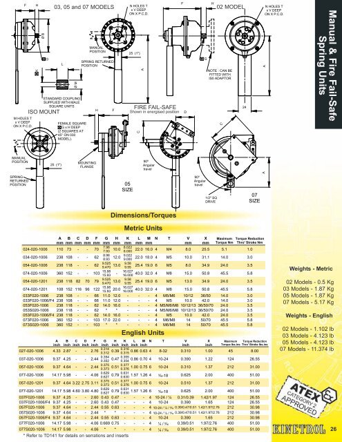
F M HOLES T x V DEEP ON X P.C.D. H K Ø B G 03, 05 and 07 MODELS L Ø M STANDARD COUPLING SUPPLIED WITH MALE SQUARE UNITS ISO MOUNT FEMALE SQUARE G x H DEEP (2 SQUARES AT 45° ON 030 MODEL). MANUAL POSITION SPRING RETURNED POSITION H F N HOLES T x V DEEP ON X P.C.D. 25 (1") FIRE FAIL-SAFE Shown in energised position C A F D G H 02 MODEL NOTE : CAN BE FITTED WITH IS0 ADAPTOR C 24 N HOLES T x V DEEP ON X P.C.D. A Manual & Fire Fail-Safe Spring Units MANUAL POSITION 25 (1") MOUNTING FLANGE 90º Angular travel A SPRING RETURNED POSITION 05 SIZE 90º Angular travel 1/2" SQ DRIVE 07 SIZE Dimensions/Torques Metric Units A mm B mm C mm D mm F mm 024-020-1006 110 73 - - 70 034-020-1006 238 108 - - 62 G mm 7.98 7.93 8.98 8.93 H mm K mm 8.022 10.0 8.000 9.022 12.0 9.000 054-020-1006 238 118 - - 62 9.525 9.58 13.0 9.470 9.55 074-020-1006 360 152 - - 103 15.98 15.93 * Refer to TD141 for details on serrations and inserts - L mm M mm English Units N T V mm X mm Maximum Torque Reduction Torque Nm Thro' Stroke Nm 22.0 16.0 4 M4 8.0 25.5 5.1 1.0 22.0 18.0 4 M5 10.0 31.1 14.0 3.0 25.4 19.0 6 M5 8.0 34.9 24.0 3.5 16.027 40.0 32.0 4 M8 15.0 50.8 45.5 5.8 16.000 054-020-1201 238 118 82 70 79 9.525 9.58 13.0 25.4 19.0 6 M5 13.0 34.9 24.0 3.5 9.470 9.55 074-020-1201 108 152 116 96 122 15.98 16.027 20.0 40.0 32.0 4 M8 15.0 50.8 45.5 5.8 15.93 16.000 033F020-1006 238 108 - - 66 11.0 12.0 - - - 4 M5/M6 10/12 36/50 14.0 3.0 033F020-1006/F4 238 108 - - 66 11.0 12.0 - - - 4 M5 10.0 42.0 14.0 3.0 053F020-1006 238 118 - - 62 14.0 16.0 - - - 4 M5/M6/M8 10/12/13 36/50/70 24.0 3.5 053S020-1006 238 118 - - 62 * * - - - 4 M5/M6/M8 10/12/13 36/50/70 24.0 3.5 053F020-1006/F4 238 118 - - 62 14.0 16.0 - - - 4 M5 10.0 42.0 24.0 3.5 073F020-1006 360 152 - - 103 17.0 22.0 - - - 4 M6/M8 14 50/70 45.5 5.8 073S020-1006 360 152 - - 103 * * - - - 4 M6/M8 14 50/70 45.5 5.8 A inch B inch C inch D inch F inch G inch H inch K inch L inch M N T V inch inch X inch Maximum Torque Reduction Torque lbs.ins Thro' Stroke lbs.ins 027-020-1006 4.33 2.87 - - 2.76 0.314 0.316 0.39 0.86 0.63 4 0.312 0.315 8-32 0.310 1.00 45 8.00 037-020-1006 9.37 4.25 - - 2.44 0.354 0.355 0.47 0.86 0.70 4 0.352 0.354 10-24 0.390 1.22 124 26.55 057-020-1006 9.37 4.64 - - 2.44 0.375 0.377 0.51 1.00 0.75 6 0.373 0.376 10-24 0.310 1.37 212 31.00 077-020-1006 14.17 5.98 - - 4.06 0.629 0.631 0.79 0.627 0.630 1.57 1.26 4 5 ∕16-18 0.625 2.00 400 51.00 057-020-1201 9.37 4.64 3.22 2.75 3.11 0.375 0.377 0.51 1.00 0.75 6 0.373 0.376 10-24 0.510 1.37 212 31.00 077-020-1201 14.17 5.98 4.60 3.80 4.80 0.629 0.631 0.79 0.627 0.630 1.57 1.26 6 5 ∕16-18 0.625 2.00 400 51.00 037F020-1006 9.37 4.25 - - 2.60 0.43 0.47 - - - 4 10-24 / ¼ 0.31/0.39 1.42/1.97 124 26.55 037F020-1006/F4 9.37 4.25 - - 2.60 0.43 0.47 - - - 4 10-24 0.390 1.65 124 26.55 057F020-1006 9.37 4.64 - - 2.44 0.55 0.63 - - - 4 10-24 / ¼ / 5 ∕16 0.39/0.47/0.51 1.42/1.97/2.76 212 30.98 057S020-1006 9.37 4.64 - - 2.44 * * - - - 4 10-24 / ¼ / 5 ∕16 0.39/0.47/0.51 1.42/1.97/2.76 212 30.98 057F020-1006/F4 9.37 4.64 - - 2.44 0.55 0.63 - - - 4 10-24 0.390 1.65 212 30.98 077F020-1006 14.17 5.98 - - 4.06 0.669 0.75 - - - 4 ¼ / 5 ∕16 0.39/0.51 1.97/2.76 400 51.00 077S020-1006 14.17 5.98 - - 4.06 * * - - - 4 ¼ / 5 ∕16 0.39/0.51 1.97/2.76 400 51.00 Weights - Metric 02 Models - 0.5 Kg 03 Models - 1.87 Kg 05 Models - 1.87 Kg 07 Models - 5.17 Kg Weights - English 02 Models - 1.102 lb 03 Models - 4.123 lb 05 Models - 4.123 lb 07 Models - 11.374 lb 26
- Page 1 and 2: Rotary Actuators
- Page 3 and 4: Kinetrol modular concept easily pro
- Page 5 and 6: Direction of Spring Action Spring u
- Page 7 and 8: Ultimate Mounting Flexibility Low c
- Page 9 and 10: Ordering Codes Switch Type 001 2 in
- Page 11 and 12: Switch Code Switching Operation Con
- Page 13 and 14: AS Interface Configurations AS Inte
- Page 15 and 16: Application This EL positioner can
- Page 17 and 18: The AP positioner can be directly m
- Page 19 and 20: Clear Cone Monitor The optional Cle
- Page 21 and 22: Robust modulating actuator control
- Page 23 and 24: A patented part-turn rotary actuato
- Page 25: A B G x S long Output square is sho
- Page 29 and 30: 014-100 014P100 Standard Coupling (
- Page 31 and 32: 22 9.022 9.000 18 Ø Standard Coupl
- Page 33 and 34: 40 16.027 16.000 32 Ø Standard Cou
- Page 35 and 36: 50 23.5 to radius 19.033 19.000 38
- Page 37 and 38: 56 50 Ø Standard Coupling (supplie
- Page 39 and 40: Vane Slot detail both ends M6 x 12
- Page 41 and 42: Vane Slot detail both ends M6 x 12
- Page 43 and 44: XLS MOUNT PLATE KIT SP/ASP1607 07/0
- Page 45 and 46: Kinetrol declutchable geared overri
- Page 47 and 48: Options Double acting and spring fa
- Page 49 and 50: B G1 C Standard Actuator Actuator M
- Page 51 and 52: M (A/F) ISO Flange Female Spring Re
- Page 53 and 54: I AP Positioner Dimensions External
- Page 55 and 56: 94 (3.70") 281 (11.1") APPROX STAND
- Page 57 and 58: Double Acting Torque Outputs - Engl
- Page 59 and 60: Catalogue Index Pages Kinetrol Vane
F<br />
M HOLES T<br />
x V DEEP<br />
ON X P.C.D.<br />
H<br />
K<br />
Ø B<br />
G<br />
03, 05 and 07 MODELS<br />
L<br />
Ø M<br />
STANDARD COUPLING<br />
SUPPLIED WITH MALE<br />
SQUARE UNITS<br />
ISO MOUNT<br />
FEMALE SQUARE<br />
G x H DEEP<br />
(2 SQUARES AT<br />
45° ON 030<br />
MODEL).<br />
MANUAL<br />
POSITION<br />
SPRING RETURNED<br />
POSITION<br />
H<br />
F<br />
N HOLES T<br />
x V DEEP<br />
ON X P.C.D.<br />
25 (1")<br />
FIRE FAIL-SAFE<br />
Shown in energised position<br />
C<br />
A<br />
F<br />
D<br />
G<br />
H<br />
02 MODEL<br />
NOTE : CAN BE<br />
FITTED WITH<br />
IS0 ADAPTOR<br />
C<br />
24<br />
N HOLES T<br />
x V DEEP<br />
ON X P.C.D.<br />
A<br />
Manual & Fire Fail-Safe<br />
Spring Units<br />
MANUAL<br />
POSITION<br />
25 (1")<br />
MOUNTING<br />
FLANGE<br />
90º<br />
Angular<br />
travel<br />
A<br />
SPRING<br />
RETURNED<br />
POSITION<br />
05<br />
SIZE<br />
90º<br />
Angular<br />
travel<br />
1/2" SQ<br />
DRIVE<br />
07<br />
SIZE<br />
Dimensions/<strong>To</strong>rques<br />
Metric Units<br />
A<br />
mm<br />
B<br />
mm<br />
C<br />
mm<br />
D<br />
mm<br />
F<br />
mm<br />
024-020-1006 110 73 - - 70<br />
034-020-1006 238 108 - - 62<br />
G<br />
mm<br />
7.98<br />
7.93<br />
8.98<br />
8.93<br />
H<br />
mm<br />
K<br />
mm<br />
8.022<br />
10.0<br />
8.000<br />
9.022<br />
12.0<br />
9.000<br />
054-020-1006 238 118 - - 62 9.525 9.58<br />
13.0<br />
9.470 9.55<br />
074-020-1006 360 152 - - 103 15.98<br />
15.93<br />
* Refer to TD141 for details on serrations and inserts<br />
-<br />
L<br />
mm<br />
M<br />
mm<br />
English Units<br />
N T V<br />
mm<br />
X<br />
mm<br />
Maximum <strong>To</strong>rque Reduction<br />
<strong>To</strong>rque Nm Thro' Stroke Nm<br />
22.0 16.0 4 M4 8.0 25.5 5.1 1.0<br />
22.0 18.0 4 M5 10.0 31.1 14.0 3.0<br />
25.4 19.0 6 M5 8.0 34.9 24.0 3.5<br />
16.027<br />
40.0 32.0 4 M8 15.0 50.8 45.5 5.8<br />
16.000<br />
054-020-1201 238 118 82 70 79 9.525 9.58<br />
13.0 25.4 19.0 6 M5 13.0 34.9 24.0 3.5<br />
9.470 9.55<br />
074-020-1201 108 152 116 96 122 15.98 16.027<br />
20.0 40.0 32.0 4 M8 15.0 50.8 45.5 5.8<br />
15.93 16.000<br />
033F020-1006 238 108 - - 66 11.0 12.0 - - - 4 M5/M6 10/12 36/50 14.0 3.0<br />
033F020-1006/F4 238 108 - - 66 11.0 12.0 - - - 4 M5 10.0 42.0 14.0 3.0<br />
053F020-1006 238 118 - - 62 14.0 16.0 - - - 4 M5/M6/M8 10/12/13 36/50/70 24.0 3.5<br />
053S020-1006 238 118 - - 62 * * - - - 4 M5/M6/M8 10/12/13 36/50/70 24.0 3.5<br />
053F020-1006/F4 238 118 - - 62 14.0 16.0 - - - 4 M5 10.0 42.0 24.0 3.5<br />
073F020-1006 360 152 - - 103 17.0 22.0 - - - 4 M6/M8 14 50/70 45.5 5.8<br />
073S020-1006 360 152 - - 103 * * - - - 4 M6/M8 14 50/70 45.5 5.8<br />
A<br />
inch<br />
B<br />
inch<br />
C<br />
inch<br />
D<br />
inch<br />
F<br />
inch<br />
G<br />
inch<br />
H<br />
inch<br />
K<br />
inch<br />
L<br />
inch<br />
M N T V<br />
inch<br />
inch<br />
X<br />
inch<br />
Maximum <strong>To</strong>rque Reduction<br />
<strong>To</strong>rque lbs.ins Thro' Stroke lbs.ins<br />
027-020-1006 4.33 2.87 - - 2.76 0.314 0.316<br />
0.39 0.86 0.63 4<br />
0.312 0.315<br />
8-32 0.310 1.00 45 8.00<br />
037-020-1006 9.37 4.25 - - 2.44 0.354 0.355<br />
0.47 0.86 0.70 4<br />
0.352 0.354<br />
10-24 0.390 1.22 124 26.55<br />
057-020-1006 9.37 4.64 - - 2.44 0.375 0.377<br />
0.51 1.00 0.75 6<br />
0.373 0.376<br />
10-24 0.310 1.37 212 31.00<br />
077-020-1006 14.17 5.98 - - 4.06 0.629 0.631<br />
0.79<br />
0.627 0.630 1.57 1.26 4 5<br />
∕16-18 0.625 2.00 400 51.00<br />
057-020-1201 9.37 4.64 3.22 2.75 3.11 0.375 0.377<br />
0.51 1.00 0.75 6<br />
0.373 0.376<br />
10-24 0.510 1.37 212 31.00<br />
077-020-1201 14.17 5.98 4.60 3.80 4.80 0.629 0.631<br />
0.79<br />
0.627 0.630 1.57 1.26 6 5<br />
∕16-18 0.625 2.00 400 51.00<br />
037F020-1006 9.37 4.25 - - 2.60 0.43 0.47 - - - 4 10-24 / ¼ 0.31/0.39 1.42/1.97 124 26.55<br />
037F020-1006/F4 9.37 4.25 - - 2.60 0.43 0.47 - - - 4 10-24 0.390 1.65 124 26.55<br />
057F020-1006 9.37 4.64 - - 2.44 0.55 0.63 - - - 4 10-24 / ¼ / 5 ∕16 0.39/0.47/0.51 1.42/1.97/2.76 212 30.98<br />
057S020-1006 9.37 4.64 - - 2.44 * * - - - 4 10-24 / ¼ / 5 ∕16 0.39/0.47/0.51 1.42/1.97/2.76 212 30.98<br />
057F020-1006/F4 9.37 4.64 - - 2.44 0.55 0.63 - - - 4 10-24 0.390 1.65 212 30.98<br />
077F020-1006 14.17 5.98 - - 4.06 0.669 0.75 - - - 4 ¼ / 5 ∕16 0.39/0.51 1.97/2.76 400 51.00<br />
077S020-1006 14.17 5.98 - - 4.06 * * - - - 4 ¼ / 5 ∕16 0.39/0.51 1.97/2.76 400 51.00<br />
Weights - Metric<br />
02 Models - 0.5 Kg<br />
03 Models - 1.87 Kg<br />
05 Models - 1.87 Kg<br />
07 Models - 5.17 Kg<br />
Weights - English<br />
02 Models - 1.102 lb<br />
03 Models - 4.123 lb<br />
05 Models - 4.123 lb<br />
07 Models - 11.374 lb<br />
26


