To p - ERCO
To p - ERCO
To p - ERCO

You also want an ePaper? Increase the reach of your titles
YUMPU automatically turns print PDFs into web optimized ePapers that Google loves.
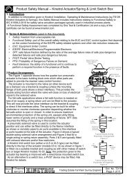
P3 On/Off Positioner<br />
The P3 On/Off positioner consists of an electronic<br />
positioning circuit mounted in a robust all-metal<br />
enclosure, which controls a ¼-turn rotary pneumatic<br />
actuator via standard on-off solenoid valves directmounted<br />
on the actuator’s own interface.<br />
The P3 circuit is designed so that its assembly can be<br />
mounted inside a standard Kinetrol limit switch box<br />
(either ULS-type, or explosion proof XLS-type), using<br />
only two screws. The P3 assembly is complete with<br />
feedback potentiometer and anti-backlash gear drive,<br />
which engages with gear teeth on the limit switch<br />
coupling to read the actuator’s position. The limit<br />
switch coupling complete with gear teeth needs to<br />
replace the standard coupling if a standard box is being<br />
retrofitted with a P3.<br />
The positioner circuit is powered by the mid-point input<br />
voltage. It functions by comparing the actual mid-point<br />
position (read by the feedback potentiometer) with the<br />
set position (set via an on-board preset, or a remote<br />
preset, or a remote 4-20mA signal). The positioner<br />
circuit uses its solid-state switched outputs to power<br />
solenoid valves which drive the actuator towards the<br />
position where the set position corresponds with the<br />
actual position. When it gets there, the solenoids are<br />
switched to hold that position.<br />
The positioner circuit incorporates a unique power<br />
supply allowing it to be powered by any of 24vDC,<br />
48vDC, 115vAC or 230vAC, 50/60 Hz, without the need<br />
for any change. The supply maintains full isolation of<br />
the low voltage control circuit from the power input line<br />
(up to 5Kv). Switching of the solenoid valve outputs is<br />
achieved through opto-isolated solid state switches<br />
which operate at all the above voltages – only the<br />
solenoid coils themselves need to be adapted<br />
specifically to the supply voltage. The use of solid state<br />
switching avoids any limitations on relay contact life.<br />
Double acting models are available as fail-free<br />
(standard), fail-down (moves clockwise or counter<br />
clockwise on loss of electrical power if air supply is still<br />
present) and fail-hold (holds position on loss of electrical<br />
and / or air supply) variants. Spring return models move<br />
in the direction of the spring on loss of electrical or air<br />
supply.<br />
An optional angle retransmit (AR) circuit can be<br />
retrofitted by plugging it into the top of the<br />
positioner circuit and fixing with three screws. The<br />
AR circuit is a 2-wire loop-powered 4-20mA<br />
device, which reads the position of the<br />
positioner’s feedback pot. It is fully functional<br />
whether or not the positioner circuit is powered,<br />
and the feedback signal is electronically isolated<br />
(ie. floating) relative to the low voltage positioner<br />
circuit (which in turn is electrically isolated from<br />
the power supply and solenoid connections).<br />
Extra solid-state switches have been incorporated<br />
on the positioner board to allow supply to both<br />
solenoid valves via a single cable for movement<br />
to the upscale position when the positioner is in<br />
spring-return or fail-down mode, while still<br />
allowing the positioner to control the two valves<br />
independently for the mid position. If the midposition<br />
input is energised, then these extra<br />
switches isolate the solenoids from the<br />
upscale/downscale inputs.<br />
The three power input lines (for up, mid, down<br />
positions) are independently fused using plug-in<br />
miniature fuses on the positioner circuit board.<br />
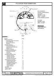
External connections are made via a multi-option<br />
connector board, which allows simultaneous<br />
connection of up to four changeover limit<br />
switches, three control supply inputs plus<br />
neutral/negative, and a single low-voltage signal.<br />
This connector board, like the positioner circuit<br />
assembly, mounts in either the standard ULS or<br />
XLS box using two screws.<br />
If an angle retransmit circuit is fitted using the low<br />
voltage signal terminal, optional 4-20mA inputs or<br />
external setpoint pot wires can be connected<br />
either directly to the terminal block on the<br />
positioner circuit or, if only three or less limit<br />
switches are in use, relayed through an unused<br />
limit switch terminal on the connector board.<br />
The limit switch box is fitted with a ground<br />
terminal which must be connected to a suitable<br />
external ground.<br />
Industrial solenoid valves which permit the use of<br />
standard quality air supplies (instrument quality air<br />
is not necessary), are direct-mounted on adaptor<br />
blocks on the side of the actuator, and electrically<br />
connected via steel-armoured flying leads with<br />
DIN sockets on the solenoid end. At the<br />
positioner end, they connect to two 2-way<br />
terminal blocks on the circuit board. A range of<br />
solenoid valve options are available, determined<br />
by the function required, the supply voltage, and<br />
whether or not the unit requires hazardous area<br />
certification. Customer selection is via the order<br />
code.<br />
19