EUROSTER 1100S - INSTRUKCJA OBSÅUGI - Logitron
EUROSTER 1100S - INSTRUKCJA OBSÅUGI - Logitron
EUROSTER 1100S - INSTRUKCJA OBSÅUGI - Logitron

You also want an ePaper? Increase the reach of your titles
YUMPU automatically turns print PDFs into web optimized ePapers that Google loves.
<strong>EUROSTER</strong> <strong>1100S</strong> – OPERATING INSTRUCTIONS<br />
1) APPLICATION<br />
<strong>EUROSTER</strong> <strong>1100S</strong><br />
The <strong>EUROSTER</strong> 1100 S is a modern differential temperature controller with 2 measurements,<br />
designed for work with 1 heat receiver in solar systems. It works together with a circulating<br />
pump in solar collector systems.<br />
In the heating circuit, the task of the controller is to force circulation between the collector<br />
and the hot water tank.<br />
INSTALLATION<br />
a. Mounting the controller:<br />
• mount the controller on a wall or a console, using two screws (expansion plugs with<br />
screws are supplied with the controller),<br />
• fix the outgoing cables to the wall, using holders.<br />
b. Mounting the sensors:<br />
• the sensors must not be immersed in liquids or installed in flue gas outlets,<br />
• install sensor 1 on the solar collector at a location intended for this purpose,<br />
• install sensor 2 on the hot water tank,<br />
• the maximum temperature measurement value is 99°C.<br />
c. Connecting the power supply cable to the pump:<br />
• connect the yellow or yellow/green wire (ground wire) to the () terminal,<br />
• connect the blue wire to the (N) terminal,<br />
• connect the brown wire to the (L) terminal.<br />
d. Checking the correct connection:<br />
• check the correct connection and screw on the pump motor terminal box cover.<br />
e. Connecting the controller:<br />
• after protecting the cables against accidental breaking, connect the power supply cable<br />
to a grounded 230V/50Hz mains socket.<br />
NOTE: The ambient temperature in the place of installation of the controller should not<br />
exceed 40°C.<br />
Wait about 30 seconds after start-up for the controller to start normal operation.<br />
2) PRINCIPLE OF OPERATION OF THE <strong>EUROSTER</strong> <strong>1100S</strong> CONTROLLER<br />
The control algorithm for the circulating pump is designed in such a way that the controller<br />
will not close the circulating pump relay, if the sensor temperature is higher than 75°C or<br />
85°C, so as to prevent the water in the tank from boiling.<br />
a. Turning on the controller:<br />
• set the switch marked with (~) (the one on the left) in the “I” position,
• upon turning on, all display segments will light for about 2 seconds, and after 1.5<br />
seconds the controller will show the current temperature of the hot water tank sensor<br />
and will turn on the circulating pump for 120 seconds.<br />
The factory settings of the threshold temperature values are the following: the upper<br />
threshold value is set at 14 degrees and the lower threshold value is set at 6 degrees.<br />
b. Display description (information display)<br />
• non-flashing digits – the hot water tank sensor temperature is displayed<br />
• flashing digits – the set temperature value is displayed<br />
• lighted green LED – the circulating pump relay is closed<br />
• in order to display the solar collector sensor temperature, press both buttons at the<br />
same time and release them. After 5 seconds the controller will automatically return to<br />
the hot water tank sensor temperature display.<br />
c. Changing the temperature values<br />
• setting the upper differential temperature value for switching on – press the lefthand<br />
button under the display (the digits will start flashing and will indicate the current<br />
set value),<br />
• setting the lower differential temperature value for switching off – press the<br />
right-hand button under the display (the digits will start flashing and will indicate the<br />
current set value),<br />
• set the desired temperature difference using the right-hand (increasing) or the left-hand<br />
(decreasing) button,<br />
• after setting the temperature, wait for about 5 seconds, until the display stops flashing<br />
and the temperature difference is stored in the memory,<br />
• the display will show the current hot water tank sensor temperature,<br />
• normally, the maximum temperature limit for the hot water tank is set at 75°C. In order<br />
to increase the heat storage capacity of the buffer reservoir, the hot water tank<br />
temperature may be changed by the user to 85°C. The tank temperature can only be<br />
changed upon turning on the controller by pressing and holding both buttons at the same<br />
time. If the display flashes once during start-up, the temperature limit is set at 75°C,<br />
and if the display flashes three times, the temperature limit is set at 85°C.<br />
d. Automatic operation<br />
• set the right-hand switch marked with (►) in the “0” position, and the (~) switch in<br />
position 1,<br />
• the controller will switch the pump on or off depending on the threshold temperature<br />
settings. If the difference between of the solar collector sensor temperature and the tank<br />
sensor temperature rises above the stored upper limit, the circulating pump will be<br />
switched on. When as a result of heating the difference between of the solar collector<br />
sensor temperature and the tank sensor temperature drops to the lower limit, the<br />
circulating pump will be switched off.<br />
e. Continuous operation:<br />
• set the switches marked with (~) and (►) in position 1,<br />
• the hot water pump will run regardless of the temperature setting of the controller and<br />
the real temperature at the sensor location – this is indicated by a lighted green LED.<br />
3) OPERATING THE CONTROLLER<br />
The factory threshold temperature settings – the upper limit is set at 14°C and the lower<br />
limit is set at 6°C, which means that the controller will switch on the pump, if the
temperature difference between the solar collector and the hot water tank is 14°C and the<br />
pump will work until the temperature difference between the sensors drops to 6°C. If the<br />
upper differential temperature is changed to a value below the lower differential<br />
temperature, the lower limit will be changed automatically so as not to be higher than the<br />
upper limit, and if the lower differential temperature is changed to a value above the upper<br />
differential temperature, the upper limit will be changed automatically so as not to be lower<br />
than the lower limit.<br />
Both threshold temperature values can be changed within the range from 0°C to 20°C.<br />
The temperatures are set with the buttons under the controller’s display.<br />
In addition, the controller is equipped with an ANTI-STOP system working at two speeds.<br />
The ANTI-STOP system operates all the time, regardless of the threshold temperature<br />
values and the temperature difference. When the solar collector temperature is higher than<br />
90°C, the ANTI-STOP system works with a high frequency, switching on every 30 minutes<br />
for 80 seconds, and when the collector temperature is lower, the system starts the pump<br />
every 14 days to run for 30 seconds.<br />
Technical data<br />
threshold temperature setting range 0°C – 20°C<br />
measurement range 1°C – 99°C<br />
supply voltage<br />
230V AC<br />
maximum load<br />
6A AC<br />
4) Kit components<br />
a. controller with sensors (collector – 25 m, tank – 5 m)<br />
b. sensor band clips<br />
c. expansion plugs<br />
d. instruction<br />
e. mounting template<br />
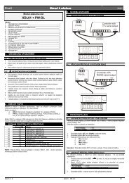
Connection diagram – connection of controller to pump and solar collector<br />
The presented diagram is simplified and does not contain all the elements required for the<br />
correct operation of the installation.<br />
hot water<br />
cold water<br />
Legend<br />
1. Controller<br />
2. Solar collector<br />
3. Hot water tank<br />
4. Collector temperature sensor<br />
5. Tank temperature sensor<br />
WARRANTY CARD<br />
Warranty conditions:<br />
<strong>EUROSTER</strong> <strong>1100S</strong> controller, serial number ........................................<br />
1) The warranty is granted for a period of 24 months from the date of sale.
2) Faulty controller together with the warranty card shall be delivered to the point of sale or<br />
directly to the manufacturer by mail.<br />
3) The manufacturer commits itself to repair faulty equipment within 14 days following the<br />
receipt thereof.<br />
4) The warranty is void in the case of mechanical damage, incorrect use or repairs made by<br />
unauthorised persons.<br />
5) All changes and amendments in the warranty card are only valid if made by an<br />
authorised person and confirmed with a signature and a stamp.<br />
6) Warranty and after-warranty repairs are made by the manufacturer only.<br />
TO BE FILLED IN BY THE POINT OF SALE<br />
date of sale<br />
company stamp and signature