
You also want an ePaper? Increase the reach of your titles
YUMPU automatically turns print PDFs into web optimized ePapers that Google loves.
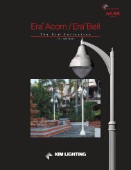
SITE /ROADWAY<br />
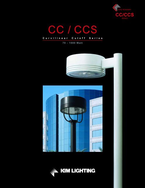
<strong>CC</strong>/<strong>CC</strong>S<br />
SERIES<br />
<strong>CC</strong> / <strong>CC</strong>S<br />
C u r v i l i n e a r C u t o f f S e r i e s<br />
70 - 1000 Watt
<strong>CC</strong>/<strong>CC</strong>S<br />
Curvilinear Cutoff Series<br />
Table of Contents<br />
Relativity 2-3<br />
Optical Design / Versatility 4-5<br />
Mechanical Design Features 6-7<br />
Installation and Maintenance 8<br />
Arm Mount<br />
Ordering Information 10-11<br />
Arm Mount<br />
Specifications 12-13<br />
Post Top Mount<br />
Ordering Information 14-15<br />
Post Top Mount<br />
Specifications 16-17<br />
Proportion Guide 19<br />
Lamp and Electrical Guide 20-21<br />
The <strong>CC</strong>/<strong>CC</strong>S Series of<br />
performance luminaires are<br />
conceived as a total integration<br />
of design and technology. <strong>Kim</strong>’s<br />
third generation of Curvilinear<br />
Cutoff luminaires represents<br />
the most current technology<br />
in specification-grade outdoor<br />
lighting.<br />
This family of cutoff luminaires<br />
is a direct response to the<br />
needs of today, engineered with<br />
tomorrow’s insight. The <strong>CC</strong>/<strong>CC</strong>S<br />
product line is designed to<br />
surpass tough demands, such<br />
as energy efficiency, glare<br />
control, light trespass, aesthetic<br />
and structural integrity, all<br />
manufactured to <strong>Kim</strong>’s standards<br />
for quality, longevity, and<br />
performance.<br />
SITE / AREA<br />
PARKING STRUCTURE<br />
ROADWAY<br />
ARCHITECTURAL FLOOD<br />
A<strong>CC</strong>ENT<br />
LANDSCAPE<br />
MAILING ADDRESS:<br />
P.O. BOX 60080<br />
CITY OF INDUSTRY, CA<br />
91716-0080<br />
BUSINESS ADDRESS:<br />
16555 EAST GALE AVENUE<br />
CITY OF INDUSTRY, CA 91745<br />
U.S.A.<br />
PHONE 626 / 968 - 5666<br />
FAX 626 / 369-2695<br />
ENTIRE CONTENTS<br />
© COPYRIGHT 2008 KIM LIGHTING INC.<br />
ALL RIGHTS RESERVED<br />
REPRODUCTION IN WHOLE OR IN PART<br />
WITHOUT PERMISSION IS STRICTLY PROHIBITED.<br />
www.kimlighting.com<br />
Printed in U.S.A.<br />
5501608081<br />
Version 1.1 (3/08)
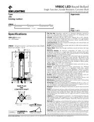
<strong>Kim</strong> <strong>Lighting</strong>’s StarView products are<br />
designated for luminaires that meet<br />
IES full cutoff requirements for use<br />
where light pollution or light trespass<br />
may be a concern and to promote the<br />
enjoyment of celestial visibility at night.<br />
KIM LIGHTING 1
00<br />
<strong>Kim</strong> <strong>Lighting</strong>’s Theory of Relativity<br />
The Relationship of Outdoor <strong>Lighting</strong> to Site and Architecture<br />
<strong>CC</strong>A Curvilinear Cutoff Arm <strong>CC</strong>P Curvilinear Cutoff Post VRB Vandal Resistant Bollard LTV Lightvault ® AFL Architectural Floodlight WF Wall Forms ®<br />
SW Site Wallforms WD Wall Director ®<br />
As Distance to Architecture Decreases, Luminaire Height and Scale Also Decreases<br />
<strong>CC</strong>A<br />
25" or 29"<br />
KIM LIGHTING’S THEORY OF RELATIVITY<br />
The purpose of this guideline is to bring a cohesive look to outdoor<br />
lighting, maximizing lighting efficiency while preserving the<br />
architectural experience. Simply stated, the <strong>Kim</strong> Theory of Relativity<br />
says “Poles belong in parking lots. And, once you leave the parking<br />
lot, the outdoor lighting should become less and less conspicuous<br />
until it becomes an integral part of the architecture.” In addition, the<br />
luminaire style and geometry should remain consistent. If this<br />
guideline is utilized, the outdoor lighting will enhance the site and<br />
architecture, bringing unity to the outdoor lighting scheme.<br />
Luminaire design and style remain constant to unify the lighting scheme<br />
<strong>CC</strong>P<br />
21" or 25"<br />
<strong>CC</strong>P<br />
17"<br />
WD<br />
View of Architecture<br />
unobstructed<br />
by poles<br />
SW<br />
VRB<br />
WF<br />
00<br />
LTV<br />
AFL<br />
SITE / ROADWAY ZONE<br />
Parking lots and roadways require luminaires on 20' - 40' poles to efficiently light<br />
these large areas. Therefore, this lighting becomes dominant and sets the design<br />
and style for all other lighting as you progress towards the building.<br />
PEDESTRIAN ZONE<br />
As you leave the parking lot and transition to<br />
pedestrian areas, poles should decrease in<br />
height to 10' - 16'. In addition, luminaires should<br />
decrease in scale, and can have more decorative<br />
features to be appreciated at the pedestrian level.<br />
LANDSCAPE / PATH ZONE<br />
Near the building, luminaires should begin<br />
to disappear, blending into the landscape<br />
and hardscape elements.<br />
BUILDING / PERIMETER ZONE<br />
No pole mounted luminaires should ever be used near the building, as they will<br />
dominate the architecture. The only exception would be the use of decorative<br />
luminaires to delineate entrances to the structure. Building mounted, architecturally<br />
compatible fixtures should be almost invisible.<br />
2 KIM LIGHTING<br />
KIM LIGHTING 3
Optical Design / Versatility<br />
Sharp Cutoff, Visual Uniformity, Maximum Pole Spacing<br />
Any one of these criteria is demanding. To achieve all three in a<br />
single luminaire requires <strong>Kim</strong>’s expertise. The <strong>CC</strong> optical system<br />
utilizes a horizontal lamp orientation to achieve sharp cutoff and a<br />
flat lens configuration for minimum visual brightness. The primary<br />
reflector panels are highly specular to achieve precise<br />
distribution and cutoff. A careful redirection of the uplight spreads<br />
light downward to properly fill the mid-ranges, while excessive<br />
straight down illumination is avoided by the elimination of<br />
downward reflecting surfaces.<br />
Rotatable Optics<br />
All <strong>CC</strong> reflectors are field rotatable in 90° increments. This allows<br />
design flexibility in producing very high illumination levels for<br />
special applications, or maintaining a constant fixture geometry in<br />
relation to surrounding architecture.<br />
A<br />
B<br />
C<br />
A. High-angle maximum candlepower and sharp cutoff are<br />
produced by the smooth specular side panels.<br />
B. A specular peened upper reflector spreads light into the<br />
mid-range, gradually increasing the intensity toward higher<br />
angles while avoiding any low-angle reflections.<br />
C. At low angles, bare lamp illumination is adequate,<br />
eliminating the need for downward reflecting surfaces to<br />
optimize uniformity.<br />
Types II, III or IV reflectors can<br />
be rotated into a parallel<br />
orientation with a standard dual<br />
mounting configuration. This<br />
provides very high illumination<br />
levels often required for<br />
tennis courts and automobile<br />
dealerships.<br />
2<br />
1<br />
1. Typical horizontal lamp luminaires produce excessive straightdown<br />
illumination in relation to the side throw. This causes poor<br />
uniformity.<br />
2. The <strong>CC</strong>’s reflectors have reduced straight-down illumination with<br />
increased side throw. This produces excellent pole spacing and<br />
uniformity.<br />
The <strong>CC</strong>/<strong>CC</strong>S Series is StarView Compliant.<br />
<strong>Kim</strong> <strong>Lighting</strong>’s StarView products are designated for luminaires<br />
that meet IES full cutoff requirements for use where light pollution or<br />
light trespass may be a concern<br />
and to promote the enjoyment of<br />
celestial visibility at night.<br />
Design Flexibility<br />
If a constant fixture alignment is desired, single or dual mounts can<br />
remain in the same orientation while rotating reflectors to change<br />
light patterns.<br />
For single post top mounts, the fixture yokes can be installed in<br />
alignment throughout the site with reflectors rotated to optimize<br />
light distribution.<br />
4 KIM LIGHTING
Four Light Distributions<br />
The <strong>CC</strong> series offers a selection of light<br />
distributions to tailor the lighting system to<br />
site geometry. The following distributions are<br />
available:<br />
Type II: Typically used as a single fixture for<br />
narrow roadways or alleys, and as a dual<br />
mount for site entrances.<br />
Available in 17", 21", 25", and 29".<br />
Type III: Typically used as a single fixture for<br />
roadways, pathways or site perimeters, and<br />
as a dual or quad mount for site lighting.<br />
Excellent for wall mounting.<br />
Available in 17", 21", 25", and 29".<br />
Type IV: Typically used as a single fixture for<br />
site perimeter or wall mounted. Excellent<br />
results with houseside shield option.<br />
Available in 17", 21", 25", and 29".<br />
Type V Square: Typically used as a single,<br />
dual or quad mounting for general open site<br />
lighting.<br />
Available in 17", 21", 25", and 29".<br />
Where light trespass must be controlled on<br />
adjacent property, houseside shielding is<br />
available on Types II, III, or IV asymmetric<br />
distributions.<br />
Seven Mounting Configurations<br />
Seven mounting configurations<br />
are available using one to four<br />
fixtures per pole, plus single wall<br />
mounting.<br />
Type II Type III Type IV Type V<br />
Forward Throw<br />
Square<br />
Superior Visual Uniformity<br />
While maintaining sharp cutoff and wide<br />
pole spacings, the <strong>CC</strong> produces excellent<br />
visual uniformity. For pole-mounted area<br />
and roadway luminaires, optimum visual<br />
uniformity is achieved when the maximumto-minimum<br />
footcandle (Fc) ratio is held<br />
below 12:1.<br />
7.8 5.1 2.7 1.5 1.4 1.5 2.7 5.1 7.8<br />
10.7 7.1 4.1 2.4 1.4 1.3 1.4 2.4 4.1 7.1 10.7<br />
5.2 4.3 3.1 2.2 1.5 1.2 1.5 2.2 3.1 4.3 5.2<br />
2.1 2.1 2.0 1.8 1.4 1.2 1.4 1.8 2.0 2.1 2.1<br />
180'<br />
1.5 1.5 1.6 1.5 1.2 1.0 1.2 1.5 1.6 1.5 1.5<br />
1.5 1.5 1.6 1.5 1.2 1.0 1.2 1.5 1.6 1.5 1.5<br />
2.1 2.1 2.0 1.8 1.4 1.2 1.4 1.8 2.0 2.1 2.1<br />
5.2 4.3 3.1 2.2 1.5 1.2 1.5 2.2 3.1 4.3 5.2<br />
10.7 7.1 4.1 2.4 1.4 1.3 1.4 2.4 4.1 7.1 10.7<br />
7.8 5.1 2.7 1.5 1.4 1.5 2.7 5.1 7.8<br />
230'<br />
Fixture No:<br />
2B/<strong>CC</strong>29A3/1000MH<br />
Mounting Height: 42'<br />
(39' pole on 3' concrete pedestal)<br />
Maintained Average: 3.27 Fc<br />
Maintained Maximum: 11.2<br />
Maintained Minimum: 1.0<br />
Maximum/Minimum: 11.2<br />
KIM LIGHTING 5
Mechanical Design Features<br />
Strength Coupled with<br />
Architectural Character<br />
Engineering and design were<br />
conceived as one discipline in<br />
the <strong>CC</strong> series. The goal was to<br />
produce a housing with very<br />
high strength, low weight and<br />
aerodynamic drag, simple<br />
geometry, and basic architectural<br />
compatibility. The logical solution<br />
was a clean cylinder accented<br />
by horizontal reveals.<br />
Our precision computer-controlled<br />
spinning process is used to<br />
produce the clean, crisp<br />
housing with consistent wall<br />
thickness and smooth sides.<br />
Three reveals are rolled into the<br />
housing for stiffening and to<br />
create a smart, classic profile.<br />
The final process adds a<br />
support flange by mechanical<br />
hemming, eliminating welds<br />
and fasteners.<br />
High Strength Yoke<br />
Post top mounted <strong>CC</strong>s utilize<br />
<strong>Kim</strong>’s unique yoke configuration<br />
which optimizes component<br />
strength while reducing stress<br />
on the welds. The key element<br />
of this design is a single tube<br />
system which spans the lens<br />
frame with longitudinal welding<br />
at the hub. This design<br />
efficiently transfers the fixture<br />
weight to the center hub and<br />
away from the welds. Stress at<br />
the weld is minimized to resist<br />
wind and vibration forces. The<br />
base hub serves as a splice<br />
compartment and completes<br />
the horizontal-plane design<br />
developed in the housing.<br />
Heavy cast<br />
aluminum lens frame<br />
Cast Aluminum splice<br />
compartment cover<br />
360° welding of support arm on<br />
inside surface of lens frame<br />
One-piece heavy<br />
tubular aluminum arms<br />
Cast Aluminum base<br />
and splice compartment<br />
Longitudinal<br />
arm welds<br />
6 KIM LIGHTING
Aluminum<br />
•<br />
Titanated<br />
•<br />
Zirconium<br />
Conversion<br />
Coating<br />
•<br />
Powder Coat<br />
Durable Powder<br />
Coat Finish<br />
<strong>Kim</strong> <strong>Lighting</strong>’s state-of-the-art<br />
powder coat paint system is<br />
engineered to provide the highest<br />
quality finish with absolute<br />
paint adhesion under weather<br />
extremes. The Super TGIC<br />
thermoset polyester powder<br />
coat finish is applied over a<br />
titanated zirconium conversion<br />
coating. This finish system has<br />
exceeded the A.S.T.M. 2500<br />
hour salt spray test.<br />
Eight Stage Finish<br />
1. Power wash and degrease.<br />
2. Detergent tank bath.<br />
3. Clear water rinse bath.<br />
4. Premium titanated zirconium<br />
conversion coating as used<br />
in the automobile industry.<br />
5. Clear water rinse bath.<br />
6. Dry off oven.<br />
7. Powder coating, 2.5 mil<br />
nominal thickness.<br />
8. Bake for 20 minutes at<br />
410°F.<br />
Low E.P.A. Housing and Components<br />
The choice between round or square housings becomes a<br />
“no contest” selection when the effect of wind is compared.<br />
A round housing produces 40% less E.P.A. (Effective Projected<br />
Area) than a square housing having the same width and height.<br />
This translates to a large potential savings, as lighter gauge poles<br />
may be utilized.<br />
Square Luminaire<br />
Round Luminaire<br />
25" 25"<br />
Coefficient of Drag (CD) 1.2 0.7<br />
EPA 2.5 1.5<br />
Comparison of 25" round and square arm mounted luminaires<br />
shows 40% less E.P.A. for the round unit. The same percentage<br />
decrease also applies to post top mounted fixtures.<br />
Sealed Optics<br />
In outdoor lighting it is not enough<br />
to seal the optical chamber from<br />
outside air, moisture and insects.<br />
Some of these contaminant’s<br />
can also enter through internal<br />
wireways, which is why all <strong>CC</strong><br />
optics are die-cast and totally<br />
sealed inside and out. This<br />
assures maximum performance<br />
between maintenance cycles<br />
which are typically three to<br />
five years.<br />
Sealed Reflector<br />
Module<br />
Housing<br />
Self-Retained<br />
Screw<br />
Flat Tempered<br />
Glass Lens<br />
Silicone<br />
Lens Gasket<br />
Cast Aluminum<br />
Lens Frame<br />
KIM LIGHTING 7
Installation and Maintenance<br />
Maintenance and Access<br />
Fast installation and easy maintenance are achieved by modular<br />
construction. Hinged lens frames (arm mounts) and housings (post<br />
top mounts) lock in the open position freeing both hands for work.<br />
Reflectors snap out for easy access to the housing interior.<br />
The ballast module is factory prewired with quick-disconnect plugs,<br />
and mounts inside the housing with keyhole slots. Pole mounting<br />
uses the least number of fasteners, maintaining simple,<br />
clean detailing.<br />
Prewired ballast module<br />
Post Top Installation<br />
Post top mounts can be<br />
specified with <strong>Kim</strong>’s patented<br />
wedge grip. A single concealed<br />
bolt attaches the fixture.<br />
Arm Mount Installation<br />
Arm mounts utilize a draw-bolt<br />
system concealed within the<br />
arm’s internal centering guides.<br />
8 KIM LIGHTING
KIM LIGHTING 9
Ordering Information<br />
Curvilinear Arm Mount<br />
<strong>CC</strong>/<strong>CC</strong>S<br />
17" - 29" Arm Mount<br />
70 to 1000 Watt<br />
Ordering Example:<br />
For Standard Fixture and Pole<br />
1 Mounting:<br />
3Y configuration is available<br />
for round poles only.<br />
2 Fixture:<br />
Cat. No. designates <strong>CC</strong>/<strong>CC</strong>S<br />
fixture and light distribution.<br />
<strong>CC</strong> fixtures have 3 horizontal<br />
reveals.<br />
<strong>CC</strong>S fixtures have 1 horizontal<br />
groove.<br />
See the <strong>Kim</strong> Site/Roadway<br />
Optical Systems Catalog for<br />
detailed information on reflector<br />
design and application.<br />
3 Electrical Module:<br />
PMH = Pulse Start<br />
Metal Halide<br />
MH = Metal Halide<br />
HPS = High Pressure Sodium<br />
PL = Compact Fluorescent<br />
Lamp Lamp Line<br />
Watts Type Volts<br />
400 MH 277<br />
4 Finish:<br />
Super TGIC powder coat paint<br />
over titanated zirconium<br />
conversion coating.<br />
Mounting Fixture Electrical Module Finish Options Accent Reveals Pole<br />
1A / <strong>CC</strong>25A3 / 400MH277 / LG-P/AA05 / BL-REV / PRA30-6250A / LG-P<br />
1 2 3 4 5-11 12 13<br />
Plan View:<br />
Fixture<br />
For <strong>CC</strong> only.<br />
See separate <strong>Kim</strong> Pole Catalog.<br />
Omit for 1W Wall Mount.<br />
Cat. No: 1A 2B 2L 3T 3Y 4C 1W<br />
EPA 17": 0.9 1.8 1.6 2.5 2.5 2.8<br />
EPA 21": 1.2 2.4 2.2 3.4 3.4 3.9<br />
EPA 25": 1.5 3.0 2.7 4.3 4.3 4.9<br />
EPA 29": 1.8 3.6 3.3 5.2 5.2 5.9<br />
<strong>CC</strong><br />
<strong>CC</strong><br />
<strong>CC</strong><br />
<strong>CC</strong><br />
17"<br />
21"<br />
25"<br />
29"<br />
<strong>CC</strong>S<br />
<strong>CC</strong>S<br />
<strong>CC</strong>S<br />
<strong>CC</strong>S<br />
<strong>CC</strong>/<strong>CC</strong>S 17"<br />
70PMH120 70HPS120 175MH120<br />
70PMH208 70HPS208 175MH208<br />
70PMH240 70HPS240 175MH240<br />
70PMH277 70HPS277 175MH277<br />
70PMH347 70HPS347 175MH347<br />
70PMH480 70HPS480 175MH480<br />
100PMH120 100HPS120<br />
100PMH208 100HPS208<br />
100PMH240 100HPS240<br />
100PMH277 100HPS277<br />
100PMH347 100HPS347<br />
100PMH480 100HPS480<br />
150PMH120 150HPS120<br />
150PMH208 150HPS208<br />
150PMH240 150HPS240<br />
150PMH277 150HPS277<br />
150PMH347 150HPS347<br />
150PMH480 150HPS480<br />
42PL120<br />
42PL208<br />
42PL240<br />
42PL277<br />
57PL120<br />
57PL208<br />
57PL240<br />
57PL277<br />
60PL120<br />
60PL208<br />
60PL240<br />
60PL277<br />
Wall<br />
Mount<br />
Light Distribution: Type II Type III Type IV Type V<br />
Full Cutoff Full Cutoff Full Cutoff Square<br />
Full Cutoff<br />
Cat. No.: <strong>CC</strong>17A2 <strong>CC</strong>17A3 <strong>CC</strong>17A4 <strong>CC</strong>17A5<br />
<strong>CC</strong>S17A2 <strong>CC</strong>S17A3 <strong>CC</strong>S17A4 <strong>CC</strong>S17A5<br />
Light Distribution: Type II Type III Type IV Type V<br />
Full Cutoff Full Cutoff Full Cutoff Square<br />
Full Cutoff<br />
Cat. No.: <strong>CC</strong>21A2 <strong>CC</strong>21A3 <strong>CC</strong>21A4 <strong>CC</strong>21A5<br />
<strong>CC</strong>S21A2 <strong>CC</strong>S21A3 <strong>CC</strong>S21A4 <strong>CC</strong>S21A5<br />
Light Distribution: Type II Type III Type IV Type V<br />
Full Cutoff Full Cutoff Full Cutoff Square<br />
Full Cutoff<br />
Cat. No.: <strong>CC</strong>25A2 <strong>CC</strong>25A3 <strong>CC</strong>25A4 <strong>CC</strong>25A5<br />
<strong>CC</strong>S25A2 <strong>CC</strong>S25A3 <strong>CC</strong>S25A4 <strong>CC</strong>S25A5<br />
Light Distribution: Type II Type III Type IV Type V<br />
Full Cutoff Full Cutoff Full Cutoff Square<br />
Full Cutoff<br />
Cat. No.: <strong>CC</strong>29A2 <strong>CC</strong>29A3 <strong>CC</strong>29A4 <strong>CC</strong>29A5<br />
<strong>CC</strong>S29A2 <strong>CC</strong>S29A3 <strong>CC</strong>S29A4 <strong>CC</strong>S29A5<br />
<strong>CC</strong>/<strong>CC</strong>S 21" and 25"<br />
250PMH120 175MH120 150HPS120<br />
250PMH208 175MH208 150HPS208<br />
250PMH240 175MH240 150HPS240<br />
250PMH277 175MH277 150HPS277<br />
250PMH347 175MH347 150HPS347<br />
250PMH480 175MH480 150HPS480<br />
320PMH120 250MH120 250HPS120<br />
320PMH208 250MH208 250HPS208<br />
320PMH240 250MH240 250HPS240<br />
320PMH277 250MH277 250HPS277<br />
320PMH347 250MH347 250HPS347<br />
320PMH480 250MH480 250HPS480<br />
350PMH120 400MH120 400HPS120<br />
350PMH208 400MH208 400HPS208<br />
350PMH240 400MH240 400HPS240<br />
350PMH277 400MH277 400HPS277<br />
350PMH347 400MH347 400HPS347<br />
350PMH480 400MH480 400HPS480<br />
400PMH120<br />
400PMH208<br />
400PMH240<br />
400PMH277<br />
400PMH347<br />
400PMH480<br />
<strong>CC</strong>/<strong>CC</strong>S 29"<br />
750PMH120 750HPS120<br />
750PMH208 750HPS208<br />
750PMH240 750HPS240<br />
750PMH277 750HPS277<br />
750PMH347 750HPS347<br />
750PMH480 750HPS480<br />
1000PMH120 1000HPS120<br />
1000PMH208 1000HPS208<br />
1000PMH240 1000HPS240<br />
1000PMH277 1000HPS277<br />
1000PMH347 1000HPS347<br />
1000PMH480 1000HPS480<br />
1000MH120<br />
1000MH208<br />
1000MH240<br />
1000MH277<br />
1000MH347<br />
1000MH480<br />
Color: Black Dark Bronze Light Gray Stealth Gray ® Platinum Silver White Custom Colors<br />
Cat. No.: BL DB LG SG PS WH <strong>CC</strong><br />
Consult representative<br />
for custom colors.<br />
10 KIM LIGHTING
5 Optional Photocell:<br />
Factory installed photocell in<br />
housing with fully gasketed<br />
sensor on side wall.<br />
✳ Fixture with photocell<br />
s slave unit(s)<br />
Photocell<br />
Mounting (see page 10) Wattage per fixture Voltage Cat. No.<br />
✳ s s<br />
✳ s<br />
s<br />
✳<br />
1A,1W 2B 2L 3T, 3Y<br />
s<br />
s s 4C<br />
s<br />
✳<br />
✳<br />
✳<br />
s<br />
4C<br />
150 to<br />
400W<br />
150 to<br />
250W<br />
400W<br />
750 &<br />
1000W<br />
Each<br />
fixture<br />
has a<br />
photocell<br />
120 A-30<br />
208 A-31<br />
240 A-32<br />
277 A-33<br />
480 A-34<br />
347 A-35<br />
120 2A-30<br />
208 2A-31<br />
240 2A-32<br />
277 2A-33<br />
480 2A-34<br />
347 2A-35<br />
6 Optional Convex Glass<br />
Lens:<br />
Convex Lens<br />
Cat. No.: CGL<br />
Tempered convex glass lens replaces standard flat lens.<br />
NOTE: Changes Full Cutoff to Cutoff.<br />
7 Optional Polycarbonate<br />
Lens:<br />
Polycarbonate<br />
Lens<br />
Cat. No.:<br />
L17 for 17" models<br />
L21 for 21" models<br />
L25 for 25" models<br />
Polycarbonate Lens replaces standard tempered glass lens.<br />
250 watt maximum. May be used with 400HPS in outdoor<br />
locations were ambient air temperature during fixture operation<br />
will not exceed 85°F. See “CAUTION” on page 13.<br />
8 Optional Houseside<br />
Shield:<br />
HS for flat lens only<br />
Cat. No.: HS<br />
Cat. No.: HSC<br />
For 17", 21", and 25" models with Types II, III, or IV distributions only.<br />
Recommended for use with clear lamps only. Effectiveness is<br />
reduced for coated lamps.<br />
For fixtures with optional convex glass lens or polycarbonate lens.<br />
Not for use with Type V light distributions.<br />
HSC for convex lens or polycarbonate lens<br />
9 Optional Vertical<br />
Slipfitter Mounts:<br />
Allows standard fixture and arm<br />
to be mounted to poles having<br />
a 2" pipe-size steel tenon<br />
(2C" O.D. x 4K" min. length).<br />
Slipfitter<br />
Cat. No.<br />
Cat. No.<br />
VSF-1A<br />
SVSF-1A<br />
VSF-2B<br />
SVSF-2B<br />
VSF-2L<br />
SVSF-2L<br />
VSF-3T<br />
SVSF-3T<br />
VSF-3Y<br />
VSF-4C 4" Round SVSF-4C 4" Square<br />
Mounting Configuration<br />
1A - Single arm mount<br />
2B - 2 at 180°<br />
2L - 2 at 90°<br />
3T - 3 at 90°<br />
3Y - 3 at 120°<br />
4C - 4 at 90°<br />
10 Optional Support Arm:<br />
NOTE: Refer to <strong>Kim</strong> <strong>Lighting</strong>’s<br />
Architectural Arms Catalog for<br />
complete details.<br />
Table shows EPA for fixture<br />
and arm.<br />
1<br />
Same as standard arm<br />
Arm Cat. No.: AA01 AA03 AA05 AA07 AA09 AA11<br />
Swept Swept Upsweep Upsweep Uplift Adjustable Uplift Adjustable<br />
Solid Arm Hollow Arm Solid Arm Hollow Arm Aluminum Arm Stainless Steel Arm<br />
Mounting Cat. No.<br />
Fixture Arm Cat No. 1A 2B 2L 3T 3Y 4C<br />
<strong>CC</strong>17A AA01 1.3 2.6 2.0 3.3 3.3 3.6<br />
AA03 1.0 2.0 1.7 2.7 2.7 3.0<br />
AA05 1.5 3.0 2.2 3.7 3.7 4.0<br />
AA07 1.1 2.2 1.8 2.9 2.9 3.2<br />
AA09/AA11 1.8 3.6 2.5 4.3 4.3 4.6<br />
<strong>CC</strong>21A AA01 1.6 3.2 2.6 4.2 4.2 4.7<br />
AA03 1.3 2.6 2.3 3.6 3.6 4.1<br />
AA05 1.8 3.6 2.8 4.6 4.6 5.1<br />
AA07 1.4 2.8 2.4 3.8 3.8 4.3<br />
AA09/AA11 2.1 4.2 3.1 5.2 5.2 5.7<br />
Mounting Cat. No.<br />
Fixture Arm Cat No. 1A 2B 2L 3T 3Y 4C<br />
<strong>CC</strong>25A AA01 1.7 3.4 2.9 4.6 4.6 5.1<br />
AA03 1.4 2.8 2.6 4.1 4.1 4.7<br />
AA05 1.9 3.8 3.1 5.1 5.1 5.7<br />
AA07 1 1.5 3.0 2.7 4.3 4.3 4.9<br />
AA09/AA11 2.2 4.4 3.4 5.4 5.4 6.9<br />
<strong>CC</strong>29A AA01 2.0 4.0 3.5 5.5 5.5 6.2<br />
AA03 1.7 3.4 3.2 4.9 4.9 5.6<br />
AA05 2.2 4.4 3.7 5.9 5.9 6.6<br />
AA07 1 1.8 3.6 3.3 5.2 5.2 5.9<br />
AA09/AA11 2.5 5.0 4.0 6.5 6.5 7.2<br />
11 Optional Horizontal<br />
Slipfitter Mount:<br />
Slipfitter<br />
Cat. No.: HSF<br />
Replaces standard mounting arm with a slipfitter for mounting<br />
to a horizontal pole davit-arm with 2" pipe-size mounting end<br />
(2C" O.D.).<br />
12 Optional Accent<br />
Reveals:<br />
For <strong>CC</strong> series only.<br />
Reveals<br />
Color: Black Dark Bronze Light Gray Stealth Gray ® Platinum Silver White Custom Colors<br />
Cat. No.: BL-REV DB-REV LG-REV SG-REV PS-REV WH-REV <strong>CC</strong>-REV<br />
Consult representative<br />
for custom colors.<br />
13 Poles:<br />
See <strong>Kim</strong> Pole Catalog for a complete selection of round and square poles in aluminum or steel.<br />
KIM LIGHTING 11
Luminaire Specifications<br />
<strong>CC</strong>/<strong>CC</strong>S Arm Mount Models<br />
Dimensions<br />
<strong>CC</strong>17A<br />
8"<br />
(203.2 mm)<br />
<strong>CC</strong>S17A<br />
<strong>CC</strong>25A<br />
<strong>CC</strong>S25A<br />
17" DIA.<br />
(431.8 mm)<br />
25" DIA.<br />
(635.0 mm)<br />
6"<br />
(152.4 mm)<br />
4K"<br />
(114.3 mm)<br />
Arm Section<br />
8"<br />
(203.2 mm)<br />
2"<br />
(50.8 mm)<br />
<strong>CC</strong>21A<br />
10"<br />
(254.0 mm)<br />
<strong>CC</strong>S21A<br />
<strong>CC</strong>29A<br />
10"<br />
(254.0 mm) 11"<br />
(279.4 mm)<br />
<strong>CC</strong>S29A<br />
21" DIA.<br />
(533.4 mm)<br />
29" DIA.<br />
(736.6 mm)<br />
4K"<br />
(114.3 mm)<br />
8"<br />
(203.2 mm)<br />
Housing: Spun aluminum. (Rollformed linear reveals; <strong>CC</strong>: Three<br />
equally spaced reveals, K" wide, separated by K" ribs, J" deep.<br />
<strong>CC</strong>S: One J" groove, J" deep.) Sidewalls have a maximum 1° of<br />
taper, and are free of welds or fasteners. A rollformed aluminum<br />
flange is hemmed into the bottom providing support for the reflector<br />
module. An internal aluminum casting provides for mounting of the<br />
electrical module plus reinforcing for side-arm mounting of the fixture.<br />
Lens Frame Assembly: One-piece cast aluminum lens frame is<br />
attached to the housing by a zinc plated cold rolled steel hinge with<br />
a stainless steel pin. Closure is by self-retained stainless steel<br />
screws; four provided for the 25" and 29" models, three provided for<br />
the 21" model, and a single screw for the 17" model. A stainless<br />
steel self-locking stop arm is provided to hold the lens frame in the<br />
open position while servicing. A F" thick clear flat tempered glass<br />
lens is fully gasketed by a one-piece extruded and vulcanized<br />
silicone gasket. Lens is retained in the frame by removable zinc<br />
plated steel clips.<br />
Standard Arm Mounting: Arm is one-piece extruded aluminum with<br />
internal bolt guides and fully radiussed top and bottom.<br />
Luminaire-to-pole attachment is by internal draw bolts, and includes<br />
a pole reinforcing plate with wire strain relief. Arm is circular cut to<br />
mate with specified round pole.<br />
Reflector Module: Specular Alzak ® optical segments are rigidly<br />
mounted within a die-cast, low copper (
NOTE: Optional Support Arms - Refer to <strong>Kim</strong> <strong>Lighting</strong>’s<br />
“Architectural Arms” Catalog for complete selection and details.<br />
Option Specifications<br />
See pages 10-11 for complete ordering information<br />
Wall Mount: A cast mounting plate of 356 alloy, low-copper (
Ordering Information<br />
Curvilinear Post Top Mount<br />
<strong>CC</strong>/<strong>CC</strong>S<br />
17" - 29" Post Top Mount<br />
70 to 1000 Watt<br />
1 Mounting:<br />
Ordering Example:<br />
For Standard Fixture and Pole<br />
17" 21" 25" 29"<br />
EPA: 0.7 1.0 1.2 1.5<br />
2 Fixture:<br />
Cat. No. designates <strong>CC</strong>/<strong>CC</strong>S<br />
fixture and light distribution.<br />
Mounting Fixture Electrical Module Finish Options Accent Reveals Pole<br />
FM / <strong>CC</strong>25P5 / 400MH277 / LG-P / A-33 / BL-REV / PRA30-6250FM / LG-P<br />
1 2 3 4 5-8 9 10<br />
For <strong>CC</strong> only. See separate <strong>Kim</strong> Pole Catalog.<br />
Cat. No: FM Flush Mount PT Post Tenon Mount DM Direct Mount<br />
Pole Top 17" 3C", 4", 4K" or 5" Dia. 2" Pipe-size Tenon (2C" O.D. x 4L" L) n/a<br />
Requirements: 21" 4", 4K", 5", or 6" Dia. 2" Pipe-size Tenon (2C" O.D. x 4L" L) 3.1" to 3.9" Dia.<br />
25" 4", 4K", 5", or 6" Dia. 2" Pipe-size Tenon (2C" O.D. x 4L" L) 3.1" to 3.9" Dia.<br />
29" 4", 4K", 5", or 6" Dia. 2" Pipe-size Tenon (2C" O.D. x 4L" L) 3.1" to 3.9" Dia.<br />
Fixture<br />
<strong>CC</strong><br />
<strong>CC</strong>S<br />
Light Distribution: Type II Type III Type IV Type V<br />
Full Cutoff Full Cutoff Full Cutoff Square<br />
Full Cutoff<br />
17"<br />
Cat. No.: <strong>CC</strong>17P2 <strong>CC</strong>17P3 <strong>CC</strong>17P4 <strong>CC</strong>17P5<br />
<strong>CC</strong>S17P2 <strong>CC</strong>S17P3 <strong>CC</strong>S17P4 <strong>CC</strong>S17P5<br />
<strong>CC</strong> fixtures have 3 horizontal<br />
reveals.<br />
<strong>CC</strong><br />
<strong>CC</strong>S<br />
Light Distribution: Type II Type III Type IV Type V<br />
Full Cutoff Full Cutoff Full Cutoff Square<br />
Full Cutoff<br />
21"<br />
Cat. No.: <strong>CC</strong>21P2 <strong>CC</strong>21P3 <strong>CC</strong>21P4 <strong>CC</strong>21P5<br />
<strong>CC</strong>S21P2 <strong>CC</strong>S21P3 <strong>CC</strong>S21P4 <strong>CC</strong>S21P5<br />
<strong>CC</strong>S fixtures have 1 horizontal<br />
groove.<br />
<strong>CC</strong><br />
25"<br />
<strong>CC</strong>S<br />
Light Distribution: Type II Type III Type IV Type V<br />
Full Cutoff Full Cutoff Full Cutoff Square<br />
Full Cutoff<br />
Cat. No.: <strong>CC</strong>25P2 <strong>CC</strong>25P3 <strong>CC</strong>25P4 <strong>CC</strong>25P5<br />
<strong>CC</strong>S25P2 <strong>CC</strong>S25P3 <strong>CC</strong>S25P4 <strong>CC</strong>S25P5<br />
See the <strong>Kim</strong> Site/Roadway<br />
Optical Systems Catalog for<br />
detailed information on reflector<br />
design and application.<br />
<strong>CC</strong><br />
29"<br />
<strong>CC</strong>S<br />
Light Distribution: Type II Type III Type IV Type V<br />
Full Cutoff Full Cutoff Full Cutoff Square<br />
Full Cutoff<br />
Cat. No.: <strong>CC</strong>29P2 <strong>CC</strong>29P3 <strong>CC</strong>29P4 <strong>CC</strong>29P5<br />
<strong>CC</strong>S29P2 <strong>CC</strong>S29P3 <strong>CC</strong>S29P4 <strong>CC</strong>S29P5<br />
3 Electrical Module:<br />
PMH = Pulse Start<br />
Metal Halide<br />
MH = Metal Halide<br />
HPS = High Pressure Sodium<br />
PL = Compact Fluorescent<br />
Lamp Lamp Line<br />
Watts Type Volts<br />
400 MH 277<br />
<strong>CC</strong>/<strong>CC</strong>S 17"<br />
70PMH120 70HPS120 175MH120<br />
70PMH208 70HPS208 175MH208<br />
70PMH240 70HPS240 175MH240<br />
70PMH277 70HPS277 175MH277<br />
70PMH347 70HPS347 175MH347<br />
70PMH480 70HPS480 175MH480<br />
100PMH120 100HPS120<br />
100PMH208 100HPS208<br />
100PMH240 100HPS240<br />
100PMH277 100HPS277<br />
100PMH347 100HPS347<br />
100PMH480 100HPS480<br />
150PMH120 150HPS120<br />
150PMH208 150HPS208<br />
150PMH240 150HPS240<br />
150PMH277 150HPS277<br />
150PMH347 150HPS347<br />
150PMH480 150HPS480<br />
42PL120<br />
42PL208<br />
42PL240<br />
42PL277<br />
57PL120<br />
57PL208<br />
57PL240<br />
57PL277<br />
60PL120<br />
60PL208<br />
60PL240<br />
60PL277<br />
<strong>CC</strong>/<strong>CC</strong>S 21" and 25"<br />
250PMH120 175MH120 150HPS120<br />
250PMH208 175MH208 150HPS208<br />
250PMH240 175MH240 150HPS240<br />
250PMH277 175MH277 150HPS277<br />
250PMH347 175MH347 150HPS347<br />
250PMH480 175MH480 150HPS480<br />
320PMH120 250MH120 250HPS120<br />
320PMH208 250MH208 250HPS208<br />
320PMH240 250MH240 250HPS240<br />
320PMH277 250MH277 250HPS277<br />
320PMH347 250MH347 250HPS347<br />
320PMH480 250MH480 250HPS480<br />
350PMH120 400MH120 400HPS120<br />
350PMH208 400MH208 400HPS208<br />
350PMH240 400MH240 400HPS240<br />
350PMH277 400MH277 400HPS277<br />
350PMH347 400MH347 400HPS347<br />
350PMH480 400MH480 400HPS480<br />
400PMH120<br />
400PMH208<br />
400PMH240<br />
400PMH277<br />
400PMH347<br />
400PMH480<br />
<strong>CC</strong>/<strong>CC</strong>S 29"<br />
750PMH120<br />
750PMH208<br />
750PMH240<br />
750PMH277<br />
750PMH347<br />
750PMH480<br />
1000PMH120<br />
1000PMH208<br />
1000PMH240<br />
1000PMH277<br />
1000PMH347<br />
1000PMH480<br />
1000MH120<br />
1000MH208<br />
1000MH240<br />
1000MH277<br />
1000MH347<br />
1000MH480<br />
750HPS120<br />
750HPS208<br />
750HPS240<br />
750HPS277<br />
750HPS347<br />
750HPS480<br />
1000HPS120<br />
1000HPS208<br />
1000HPS240<br />
1000HPS277<br />
1000HPS347<br />
1000HPS480<br />
14 KIM LIGHTING
4 Finish:<br />
Super TGIC powder coat<br />
paint over titanated zirconium<br />
conversion coating.<br />
Color: Black Dark Bronze Light Gray Stealth Gray ® Platinum Silver White Custom Colors<br />
Cat. No.: BL DB LG SG PS WH <strong>CC</strong><br />
Consult representative<br />
for custom colors.<br />
5 Optional Photocell:<br />
Factory installed photocell in<br />
housing with fully gasketed<br />
sensor on side wall.<br />
Photocell<br />
Line Volts: 120V 208V 240V 277V 480V 347V<br />
Cat. No.: A-30 A-31 A-32 A-33 A-34 A-35<br />
6 Optional Convex Glass<br />
Lens:<br />
Cat. No.: CGL<br />
Tempered convex glass lens replaces standard flat lens.<br />
NOTE: Changes Full Cutoff to Cutoff.<br />
Convex Glass Lens<br />
7 Optional Polycarbonate<br />
Lens:<br />
Cat. No.:<br />
L17 for 17" models<br />
L21 for 21" models<br />
L25 for 25" models<br />
Polycarbonate Lens replaces standard tempered glass lens.<br />
250 watt maximum. May be used with 400HPS in outdoor locations<br />
were ambient air temperature during fixture operation will not<br />
exceed 85°F. See “CAUTION” on page 17.<br />
Polycarbonate Lens<br />
8 Optional Houseside<br />
Shield:<br />
Cat. No.: HS<br />
For 17", 21", and 25" models with Types II, III, or IV distributions<br />
only. Recommended for use with clear lamps only. Effectiveness<br />
is reduced for coated lamps.<br />
HS for flat lens only<br />
Cat. No.: HSC<br />
For fixtures with optional convex glass lens or polycarbonate<br />
lens. Not for use with Type V light distributions.<br />
HSC for convex lens or<br />
polycarbonate lens<br />
9 Optional Accent<br />
Reveals:<br />
For <strong>CC</strong> series only.<br />
Reveals<br />
Color: Black Dark Bronze Light Gray Stealth Gray ® Platinum Silver White Custom Colors<br />
Cat. No.: BL-REV DB-REV LG-REV SG-REV PS-REV WH-REV <strong>CC</strong>-REV<br />
Consult representative<br />
for custom colors.<br />
10 Poles:<br />
See <strong>Kim</strong> Pole Catalog for a complete selection of round and square poles in aluminum or steel.<br />
KIM LIGHTING 15
Luminaire Specifications<br />
<strong>CC</strong>/<strong>CC</strong>S Post Top Mount Models<br />
Dimensions<br />
<strong>CC</strong>17P<br />
<strong>CC</strong>S17P<br />
<strong>CC</strong>25P<br />
<strong>CC</strong>S25P<br />
8"<br />
(203.2 mm)<br />
9"<br />
(228.6 mm)<br />
10"<br />
(254.0 mm)<br />
11"<br />
(279.4 mm)<br />
17" DIA.<br />
(431.8 mm)<br />
5K" DIA.<br />
(139.7 mm)<br />
25" DIA.<br />
(635.0 mm)<br />
8" DIA.<br />
(203.2 mm)<br />
<strong>CC</strong>21P<br />
<strong>CC</strong>S21P<br />
<strong>CC</strong>29P<br />
<strong>CC</strong>S29P<br />
10"<br />
(254.0 mm)<br />
9K"<br />
(241.3 mm)<br />
11"<br />
(279.4 mm)<br />
13"<br />
(330.2 mm)<br />
21" DIA.<br />
(533.4 mm)<br />
6L" DIA.<br />
(171.5 mm)<br />
29" DIA.<br />
(736.6 mm)<br />
8K" DIA.<br />
(215.9 mm)<br />
Housing: Spun aluminum. (Rollformed linear reveals; <strong>CC</strong>: Three<br />
equally spaced reveals, K" wide, separated by K" ribs, J" deep.<br />
<strong>CC</strong>S: One J" groove, J" deep.) Sidewalls have a maximum 1° of<br />
taper, and are free of welds or fasteners. A rollformed aluminum<br />
flange is hemmed into the bottom providing support for the reflector<br />
module. An internal aluminum casting provides for mounting of the<br />
electrical module and support for the housing hinge.<br />
Lens Frame and Yoke: One-piece cast aluminum lens frame is<br />
attached to the housing by a zinc plated cold rolled steel hinge with<br />
a stainless steel pin. Closure of the housing is by self-retained<br />
stainless steel screws; four provided for the 25" and 29" models, three<br />
provided for the 21" model, and a single screw for the<br />
17" model. A stainless steel self-locking stop arm is provided to hold<br />
the housing in the open position while servicing. A F" thick clear flat<br />
tempered glass lens is fully gasketed by a one-piece extruded and<br />
vulcanized silicone gasket. Lens is retained in the frame by<br />
removable zinc plated steel clips. Lens frame is supported at four<br />
points by two aluminum U-shaped tubular arms cradled in a cast<br />
aluminum hub. Arms are welded to the lens frame, and welded to the<br />
hub along their longitudinal axis. Hub contains a field-splice<br />
compartment, a cast aluminum cover and one of the following pole<br />
attachment means: FM - Flush Mounting, PT - Pole Tenon mounting,<br />
or DM - Direct Mounting (See page 17 for complete descriptions).<br />
Reflector Module: Specular Alzak ® optical segments are rigidly<br />
mounted within a die-cast, low copper (
Option Specifications<br />
See pages 14-15 for complete ordering information<br />
Pole Mounting<br />
FM - Flush Mounting by means of an expansion device<br />
activated by a single bolt within the splice compartment.<br />
Pole must have a plain-cut top.<br />
PT - Pole Tenon mounting by means of a cast aluminum<br />
extension sleeve containing four recessed C" stainless<br />
steel allen head set point screws. Pole must have a<br />
2" pipe-size tenon (2C" O.D. x 4L" minimum length).<br />
Pole tenon must be field drilled at one set screw location to<br />
secure against fixture rotation.<br />
DM - Direct Mounting by means of a cast aluminum<br />
extension sleeve containing four recessed C" stainless<br />
steel allen head set point screws. Pole must have a<br />
plain-cut top, 3.1" to 3.9" diameter. Pole must be field-drilled<br />
at one set screw location to secure against fixture rotation.<br />
Photocell: Factory installed photocell inside housing with a fully<br />
gasketed sensor on the side wall.<br />
Plain cut pole top<br />
3C" to 6" dia.<br />
(see page 14)<br />
2" tenon pole top<br />
Plain cut pole top<br />
3.1" through 3.9" dia.<br />
Photocell Sensor<br />
Convex Glass Lens (CGL): The F" thick clear convex tempered<br />
glass lens replaces the standard flat glass lens. Provides increased<br />
lens presence and provides a subtle improvement in uniformity<br />
where pole spacing is extreme. Increases effectiveness of houseside<br />
shielding.<br />
17" = 1L" (44.5 mm)<br />
21" = 3J" (82.6 mm)<br />
25" = 2D" (66.7 mm)<br />
29" = 3L" (95.3 mm)<br />
Polycarbonate Lens (L17, L21, and L25 only): Clear UV stabilized<br />
convex polycarbonate replaces standard flat glass lens,<br />
gasketed and integral with lens frame. 250 Watt maximum.<br />
For 21" and 25" models, 400 Watt HPS is allowable in locations where<br />
ambient air temperature will not exceed 85°F. during operation.<br />
CAUTION: Use only when vandalism is anticipated to be high. Useful<br />
life is limited by UV discoloration from sunlight and metal halide lamps.<br />
Houseside Shield (HS/HSC): Types II, III, and IV only. Fixtures with<br />
the standard flat glass lens are available with stamped aluminum<br />
louvers that pass streetside light and block houseside light, and a<br />
black panel added to the reflector to reduce houseside reflections.<br />
Fixtures with the optional convex glass lens are available with a<br />
formed aluminum shield that passes streetside light and blocks<br />
houseside light, and a black panel added to the reflector to reduce<br />
houseside reflections. Use with clear lamps only, as coated lamps<br />
reduce effectiveness.<br />
17" = 1L" (44.5 mm)<br />
21" = 3J" (82.6 mm)<br />
25" = 2D" (66.7 mm)<br />
Houseside Shield for<br />
flat lens only<br />
Convex Glass Lens<br />
Polycarbonate Lens<br />
Houseside Shield for<br />
convex lens or<br />
polycarbonate lens<br />
Accent Reveals: <strong>CC</strong> series only. Three aluminum bands riveted<br />
inside the housing reveals. Available in five standard <strong>Kim</strong> powder<br />
coat finishes. Custom colors available.<br />
KIM LIGHTING 17
18 KIM LIGHTING
Proportion Guide<br />
70 to 1000 Watt / 10' to 50' Poles<br />
50'<br />
48'<br />
29" DIA. Models: 750 to 1000 Watt<br />
35' to 50' poles<br />
46'<br />
44'<br />
42'<br />
40'<br />
38'<br />
36'<br />
34'<br />
32'<br />
This proportion diagram is intended to help visualize and<br />
select the best <strong>CC</strong> system to satisfy aesthetic requirements.<br />
Remember, the pole height also affects performance; the<br />
higher the fixture is mounted, the greater the light throw. If<br />
poles are mounted on concrete pedestals such as in parking<br />
lots, the height of the pedestal must be considered in<br />
selecting the pole height.<br />
See Architectural Arms Catalog<br />
for proportion drawings of<br />
Curvilinear Cutoff luminaire with<br />
optional Architectural Arms.<br />
25" DIA. Models: 150 to 400 Watt<br />
25' to 35' poles<br />
30'<br />
28'<br />
26'<br />
24'<br />
22'<br />
21" DIA. Models: 150 to 400 Watt<br />
20' to 30' poles<br />
20'<br />
18'<br />
5"<br />
4K" x 8"<br />
Tapered<br />
Poles<br />
6" x 10"<br />
Tapered<br />
Poles<br />
16'<br />
14'<br />
12'<br />
17" DIA. Models:<br />
70 to 175 Watt<br />
10' to 20' poles<br />
10'<br />
8'<br />
4" 4" 5" 5"<br />
6'<br />
4'<br />
2'<br />
GRADE<br />
KIM LIGHTING 19
Lamp and Electrical Guide 3<br />
70HPS 120 0.81 1.45 0.75 1.45<br />
ED-17 Clear 70 S-62 24000+ 5860 208 0.47 0.85 0.45 0.85<br />
Medium Base 240 0.40 0.75 0.37 0.75<br />
277 0.35 0.65 0.35 0.65<br />
347 0.30 0.55 0.30 0.55<br />
480 4 0.21 0.36 0.21 0.36<br />
100HPS 120 1.15 2.20 1.30 2.20<br />
ED-17 Clear 100 S-54 24000+ 8800 208 0.67 1.25 0.75 1.25<br />
Medium Base 240 0.58 1.10 0.65 1.10<br />
277 0.50 0.85 0.60 0.85<br />
347 0.39 0.70 0.45 0.70<br />
480 4 0.29 0.55 0.35 0.55<br />
150HPS 120 1.65 2.80 2.00 2.80<br />
ED-17 Clear 150 S-55 24000+ 16000 208 0.95 1.60 1.15 1.60<br />
Medium Base (<strong>CC</strong>17") 240 0.83 1.40 1.00 1.40<br />
ED-23K Clear 277 0.72 1.25 0.85 1.25<br />
Mogul Base<br />
(<strong>CC</strong>21", <strong>CC</strong>25")<br />
347 0.56 0.92 0.52 0.92<br />
480 4 0.42 0.70 0.50 0.70<br />
250HPS 120 2.50 1.70 1.65 2.50<br />
ED-18 or ET-18 Clear 250 S-50 24000+ 30000 208 1.50 1.00 0.95 1.50<br />
Mogul Base 240 1.30 0.85 0.80 1.30<br />
277 1.10 0.75 0.70 1.10<br />
347 0.93 0.70 0.60 0.93<br />
480 0.63 0.45 0.40 0.63<br />
400HPS 120 3.80 2.00 3.30 3.80<br />
ED-18 or ET-18 Clear 400 S-51 24000+ 50000 208 2.20 1.20 1.80 2.20<br />
Mogul Base 240 1.90 0.95 1.50 1.90<br />
277 1.70 0.85 1.40 1.70<br />
347 1.32 0.70 1.00 1.32<br />
480 0.97 0.55 0.75 0.97<br />
600HPS 120 5.50 3.00 5.25 5.50<br />
T-16 Clear 600 S-106 24000+ 90000 208 3.25 1.75 3.00 3.25<br />
Mogul Base 240 2.85 1.60 2.60 2.85<br />
277 2.50 1.40 2.15 2.50<br />
347 2.00 1.10 1.70 2.00<br />
480 1.43 0.75 1.20 1.43<br />
750HPS 120 6.75 3.00 6.30 6.75<br />
BT-37 Clear 750 S-111 24000+ 110000 208 4.00 1.75 3.70 4.00<br />
Mogul Base 240 3.50 1.60 3.20 3.50<br />
277 3.10 1.50 3.00 3.10<br />
347 2.50 1.20 2.30 2.50<br />
480 1.78 0.90 1.65 1.78<br />
1000HPS 120 9.50 4.80 6.40 9.50<br />
E-25 Clear 208 5.50 2.70 3.80 5.50<br />
Mogul Base 1000 S-52 24000+ 140000 240 4.75 2.40 3.20 4.75<br />
277 4.15 2.20 2.80 4.15<br />
347 3.30 1.10 2.20 3.30<br />
480 2.30 0.90 1.60 2.30<br />
METAL HALIDE 5<br />
Lamp<br />
HIGH PRESSURE SODIUM<br />
175MH 120 1.95 1.62 1.90 1.95<br />
ED-17 Clear 175 M-57 10000+ 14000 208 1.15 1.00 1.12 1.15<br />
Medium Base (<strong>CC</strong>17") 240 0.98 0.82 0.94 0.98<br />
ED-28 or BT-28 Clear 277 0.85 0.72 0.80 0.85<br />
Mogul Base<br />
(<strong>CC</strong>21", <strong>CC</strong>25")<br />
Lamp<br />
Watts<br />
ANSI<br />
Ballast<br />
Type<br />
Life<br />
(Hours)<br />
347 0.65 0.70 0.50 0.70<br />
480 4 0.45 0.45 0.35 0.45<br />
250MH 120 1.50 1.50 0.60 1.50<br />
ED-28 or BT-28 Clear 250 M-58 10000+ 23000 208 1.10 0.90 1.00 1.10<br />
Mogul Base 240 0.65 0.65 0.30 0.65<br />
277 2.50 2.10 1.50 2.50<br />
347 1.40 1.20 1.00 1.40<br />
480 2.50 2.10 2.20 2.50<br />
400MH 120 2.30 1.75 2.00 2.30<br />
ED-28 or BT-28 Clear 400 M-59 20000+ 40000 208 1.75 1.30 1.50 1.75<br />
Mogul Base 240 1.00 0.75 0.90 1.00<br />
277 4.00 3.20 2.50 4.00<br />
347 4.00 3.00 3.50 4.00<br />
480 4.00 3.00 3.50 4.00<br />
1000MH 120 4.00 3.50 2.90 4.00<br />
BT-37 Clear 1000 M-47 12000+ 115000 208 3.10 2.70 2.10 3.10<br />
Mogul Base 240 1.70 2.70 2.10 2.70<br />
277 1.32 2.20 1.20 2.20<br />
347 9.00 4.50 7.80 9.00<br />
480 9.00 4.50 7.80 9.00<br />
Initial<br />
Lumens 1<br />
Voltage<br />
Operating<br />
Amps.<br />
Open<br />
Circuit<br />
Starting<br />
Amps.<br />
Max.<br />
Amps.<br />
WARNING: Fixtures must be installed and grounded in accordance with national, state and/or local electrical codes. Failure to do so may result in serious<br />
personal injury.<br />
For lamp/ballast information outside of the U.S.A. and Canada, please consult your local <strong>Kim</strong> representative.<br />
Lamps by others.<br />
20 KIM LIGHTING
Lamp<br />
Lamp<br />
Watts<br />
ANSI<br />
Ballast<br />
Type<br />
PULSE START METAL HALIDE 5<br />
70PMH 120 0.80 1.90 0.55 1.90<br />
ED-17 Clear 70 M-98 11000+ 5000 208 0.46 1.00 0.30 1.00<br />
Medium Base 240 0.40 0.90 0.25 0.90<br />
277 0.35 0.80 0.25 0.80<br />
347 0.28 0.65 0.20 0.65<br />
480 4 0.23 0.50 0.26 0.50<br />
100PMH 120 1.15 2.30 1.20 2.30<br />
ED-17 Clear 100 M-90 12000+ 8500 208 0.66 1.40 0.80 1.40<br />
Medium Base 240 0.58 1.15 0.65 1.15<br />
277 0.50 1.00 0.60 1.00<br />
347 0.40 1.00 0.40 1.00<br />
480 4 0.30 0.60 0.25 0.60<br />
150PMH 120 1.60 3.65 1.75 3.65<br />
ED-17 Clear 150 M-102 11000+ 12600 208 1.00 2.10 1.30 2.10<br />
Medium Base 240 0.80 1.80 0.85 1.80<br />
277 0.70 1.58 0.77 1.58<br />
347 0.55 1.25 0.65 1.25<br />
480 4 0.45 1.00 0.30 1.00<br />
250PMH 120 0.65 0.65 0.30 0.65<br />
ED-28 or BT-28 Clear 250 M-138 11000+ 22500 208 1.50 1.58 1.15 1.58<br />
Mogul Base 240 1.40 1.20 1.00 1.40<br />
277 1.30 1.25 0.95 1.30<br />
347 1.25 0.70 0.96 1.25<br />
480 1.10 0.65 0.85 1.10<br />
320PMH 120 3.25 2.30 1.80 3.25<br />
ED-28 Clear 320 M-154 20000+ 30000 208 1.90 1.35 1.05 1.90<br />
Mogul Base M-132 240 1.65 1.15 0.90 1.65<br />
277 1.40 1.00 0.80 1.40<br />
347 1.10 0.80 0.70 1.10<br />
480 0.80 0.60 0.45 0.80<br />
350PMH 120 3.40 2.20 2.20 3.40<br />
ED-28 Clear 350 M-131 20000+ 33000 208 2.00 1.30 1.30 2.00<br />
Mogul Base 240 1.70 1.10 1.10 1.70<br />
277 1.50 1.00 1.00 1.50<br />
347 1.20 0.80 0.85 1.20<br />
480 0.85 0.60 0.60 0.85<br />
400PMH 120 1.00 0.75 0.90 1.00<br />
ED-28 Clear 400 M-135 15000+ 40000 208 4.00 3.20 2.50 4.00<br />
Mogul Base 240 4.00 3.70 2.50 4.00<br />
277 2.20 1.80 1.40 2.20<br />
347 1.93 1.60 1.20 1.93<br />
480 2.00 1.60 1.20 2.00<br />
750PMH 120 2.30 1.90 1.90 2.30<br />
BT-37 Clear 750 M-149 12000+ 68000 208 2.10 1.60 1.60 2.10<br />
Mogul Base 240 1.80 0.90 1.40 1.80<br />
277 1.75 1.25 1.45 1.75<br />
347 1.40 0.95 1.20 1.40<br />
480 1.00 0.63 0.85 1.00<br />
1000PMH 120 4.50 2.30 3.70 4.50<br />
BT-37 Clear 1000 M-141 9000+ 107800 208 3.90 2.20 3.20 3.90<br />
Mogul Base 240 2.25 1.20 1.90 2.25<br />
277 9.20 6.00 5.70 9.20<br />
347 5.30 4.90 2.40 5.30<br />
480 4.60 3.10 2.30 4.60<br />
COMPACT FLUORESCENT 1<br />
Life<br />
(Hours)<br />
42PL 2 120 – – – 0.39<br />
42 – 12000 3200 208 – – – 0.23<br />
240 – – – 0.20<br />
277 – – – 0.17<br />
57PL 2,3 120 – – – n/a<br />
57 – 12000 4300 208 – – – n/a<br />
240 – – – n/a<br />
277 – – – n/a<br />
60PL 2,3 120 – – – n/a<br />
60 – 20000 4000 208 – – – n/a<br />
240 – – – n/a<br />
277 – – – n/a<br />
Initial<br />
Lumens 1<br />
Voltage<br />
Operating<br />
Amps.<br />
Open<br />
Circuit<br />
Starting<br />
Amps.<br />
Max.<br />
Amps.<br />
NOTES:<br />
1<br />
All initial lumen values shown may vary, from one manufacturer to another. Consult lamp manufacturer’s data for exact lumen and life data.<br />
2<br />
Multiple CFL lamp configurations (ie, two 42W lamps) are possible with certain optical systems. Consult factory for details.<br />
3<br />
Lamp and electrical data supplied for reference purposes only. All initial lumen values shown may vary from one manufacturer to another. Consult lamp manufacturer’s data<br />
for exact lumen and life data.<br />
4<br />
480 volt with medium base lamp sockets may require approval by the local building code authority.<br />
5<br />
CAUTION: All manufacturers of metal halide lamps recommend turning them off for 15 minutes once per week when under continuous operation. This will reduce the<br />
risk of arc tube rupture at end of life. Also, color temperature may differ between manufacturers of metal halide lamps. See lamp manufacturers’ specification sheets.<br />
KIM LIGHTING 21