50-75MHz Bandpass filter with some interesting ... - G4JNT
50-75MHz Bandpass filter with some interesting ... - G4JNT
50-75MHz Bandpass filter with some interesting ... - G4JNT

You also want an ePaper? Increase the reach of your titles
YUMPU automatically turns print PDFs into web optimized ePapers that Google loves.
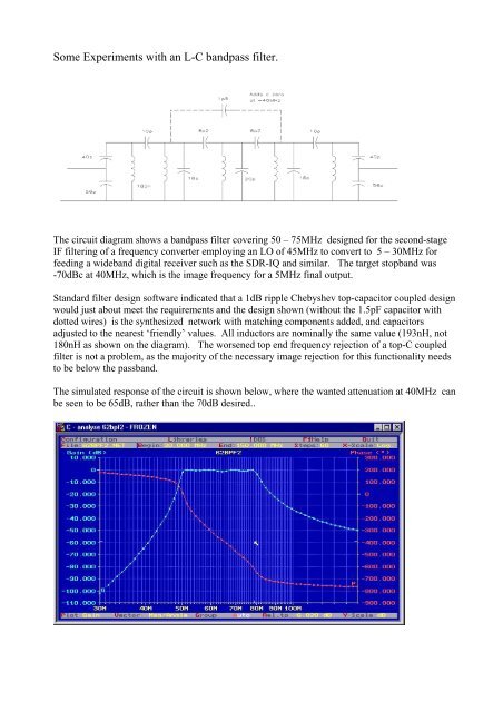
Some Experiments <strong>with</strong> an L-C bandpass <strong>filter</strong>.<br />
The circuit diagram shows a bandpass <strong>filter</strong> covering <strong>50</strong> – <strong>75MHz</strong> designed for the second-stage<br />
IF <strong>filter</strong>ing of a frequency converter employing an LO of 45MHz to convert to 5 – 30MHz for<br />
feeding a wideband digital receiver such as the SDR-IQ and similar. The target stopband was<br />
-70dBc at 40MHz, which is the image frequency for a 5MHz final output.<br />
Standard <strong>filter</strong> design software indicated that a 1dB ripple Chebyshev top-capacitor coupled design<br />
would just about meet the requirements and the design shown (<strong>with</strong>out the 1.5pF capacitor <strong>with</strong><br />
dotted wires) is the synthesized network <strong>with</strong> matching components added, and capacitors<br />
adjusted to the nearest ‘friendly’ values. All inductors are nominally the same value (193nH, not<br />
180nH as shown on the diagram). The worsened top end frequency rejection of a top-C coupled<br />
<strong>filter</strong> is not a problem, as the majority of the necessary image rejection for this functionality needs<br />
to be below the passband.<br />
The simulated response of the circuit is shown below, where the wanted attenuation at 40MHz can<br />
be seen to be 65dB, rather than the 70dB desired..
But then, I started wondering:<br />
In any bandpass <strong>filter</strong> consisting of coupled resonantors, real zeros (sharp nulls) can be added by<br />
cross-coupling non-adjacent resonators, and this is often done to improve the cutoff and sharpen<br />
the ilter edge response.. Low and high pass elliptic <strong>filter</strong>s generate real zeros for deep nulls in the<br />
stopband by adding resonating C or L components to series or shunt elements.<br />
My recollection from a dark past suggested that for bandpass deigns, these zeros always came in<br />
pairs, spaced either side of the passband.<br />
So, as an experiment, I added a few pF between stages 2 and 4 to see what happened, and analysed<br />
the result. Rather satisfactorily, a value of 1.5pF gave a null pretty close to 40MHz, and the<br />
rejection in this region was improved by at least another 10dB – just what was wanted. The ripple<br />
was slightly worse, but I can live <strong>with</strong> that – ultimately software can correct the amplitude<br />
response.<br />
The plot of the <strong>filter</strong> response is shown below.<br />
A very sucessful outcome from just idly playing around <strong>with</strong> a circuit analysis package!<br />
But where is the other zero that should be there, above the passband Searching all over the<br />
frequency response there is nothing!<br />
I can only assume that since a top-capacitor-coupled bandpass design is not truly symmetrical – as<br />
is obvious from the significantly lower stopband rejection above the centre frequency than below it<br />
- presumably the symmetrical argument disappears.<br />
But it would be nice to know why there is only the one real zero.<br />
(Incidently, I did try a feedback inductor instead of a capacitor, but all that did is destroy the<br />
passband response)<br />
… now to build a prototype.