50W Mono Hi-Fi Audio Power Amplifier Module ... - Quasar Electronics
50W Mono Hi-Fi Audio Power Amplifier Module ... - Quasar Electronics
50W Mono Hi-Fi Audio Power Amplifier Module ... - Quasar Electronics

Create successful ePaper yourself
Turn your PDF publications into a flip-book with our unique Google optimized e-Paper software.
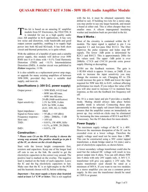
QUASAR PROJECT KIT # 3106 - <strong>50W</strong> <strong>Hi</strong>-<strong>Fi</strong> <strong>Audio</strong> <strong>Amplifier</strong> <strong>Module</strong><br />
T<br />
his kit is based on an amazing IC amplifier<br />
module from ST <strong>Electronics</strong>, the TDA7294. It<br />
is intended for use as a high quality audio<br />
class AB amplifier in hi-fi applications. It has very<br />
low noise and distortion, wide bandwidth and good<br />
output current capability, enabling it to supply high<br />
power into both 4Ω and 8Ω loads. It has both short<br />
circuit and thermal protection, so is quite robust.<br />
With the addition of a handful of parts and a suitable<br />
power supply, this module will deliver over <strong>50W</strong><br />
RMS into 4 or 8 ohms with < 0.1% Total Harmonic<br />
Distortion (THD) and < 0.1% Intermodulation<br />
Distortion (IMD). A similar circuit was published in<br />
Elektor magazine, 11/96.<br />
It is also suitable as a replacement power amp stage,<br />
or upgrade for many existing amplifiers of between<br />
30W-<strong>50W</strong>, provided they have a suitable dual<br />
supply, and most do.<br />
Specifications (± 35V D.C. power supply)<br />
Output power : > <strong>50W</strong> RMS, 4-8 Ω load<br />
~ 80W into 4Ω max.<br />
~ 60W into 8Ω max.<br />
Gain 24 dB (30dB modification)<br />
Input sensitivity : 1.3V for <strong>50W</strong>, 8 ohm<br />
0.9V for <strong>50W</strong>, 4 ohm<br />
(0.6V, <strong>50W</strong>, 8Ω, G=30dB)<br />
Input impedance : 10kΩ<br />
Signal-to-Noise ratio : > 95 dB, (>105 dBA)<br />
Frequency response : ~ 20Hz - 200kHz, –3 dB<br />
Slew rate : > 10V/uS<br />
THD : < 0.01%, 1W-40W,1kHz<br />
< 0.1%, at <strong>50W</strong>, 20-20kHz<br />
IMD : < 0.01%, 1W<br />
Construction :<br />
* Please note C6 on the PCB overlay is shown the<br />
wrong way around. The positive should go to pin 6<br />
of the IC, as shown on the circuit diagram.<br />
Start with the lowest height components first,<br />
resistors and capacitors. Keep one of the longer lead<br />
off cuts to use as the link. Be careful to get the<br />
electrolytic capacitors in the correct way around. The<br />
positive lead is marked on the overlay. The negative<br />
lead is marked on the body of each capacitor. Leave<br />
the IC and the big electrolytic capacitors to last.<br />
Make sure that the IC is at right-angles to the PCB<br />
and the heatsink chosen will fit, before soldering.<br />
Important : You must supply a heavy duty heatsink<br />
rated at least 1.4 o C/W or better. This is not supplied<br />
with the kit, it must be obtained separately then<br />
drilled to suit. If building two kits for a stereo amp,<br />
you may prefer to use one larger heatsink, and mount<br />
a board at either end. This is often cheaper than two<br />
smaller ones. A silicon impregnated insulating<br />
washer and insulation bush are provided in the kit.<br />
How it Works :<br />
Most of the circuitry is contained within the IC<br />
module. The input signal is applied to pin 3 via<br />
capacitor C1 and low-pass filter R1/C2. The filter<br />
improves the pulse response and helps stop RF<br />
signals. The lower -3dB point is determined by<br />
R2/C1 and R4/C3. This is approximately 20Hz for<br />
the values used. The upper -3dB point is over<br />
200kHz. C7/C8 and C9/C10 provide extra power<br />
supply filtering or decoupling.<br />
R3/R4 are the feedback resistors. The gain is<br />
1+R3/R4 which is approx 16 times, or 24dB. If you<br />
wish to increase the input sensitivity you may<br />
change the resistors to suit. Changing R3 to 22k<br />
would increase the gain to 30dB and lower the input<br />
required for <strong>50W</strong> into 8Ω, to 0.6V, without affecting<br />
performance too much. If you reduce the value of R4<br />
you will also need to increase C3 to maintain bass<br />
response, as this sets the feedback low frequency roll<br />
off.<br />
Pin 10 is a mute input and pin 9 provides a standby<br />
mode. Muting should always take place before<br />
standby mode is selected. Connecting these pins<br />
permanently to the supply rail (insert links provided)<br />
ensures that the amplifier comes on immediately on<br />
power up. Any switch-on clicks may be eliminated<br />
by increasing the time constants of R5/C4 and R6/C5<br />
if necessary. See the ST data sheet for more details.<br />
<strong>Power</strong> Supply :<br />
The maximum supply voltage of the IC is ± 40V.<br />
However the maximum dissipation of the IC can be<br />
exceeded even at a lower voltage. Therefore the<br />
supply voltage used need not be more than ± 35V.<br />
This can be constructed using a 50V center tapped<br />
transformer, a diode bridge rated at 5A (min.) and a<br />
pair of electrolytic capacitors, as shown below.<br />
A lower secondary voltage transformer could also be<br />
used but the reduced DC voltage will result in less<br />
power output into 8 ohms. You can still obtain <strong>50W</strong><br />
into 4 ohms with only 24V supply rails. A 36V C.T.<br />
transformer will give you approx ± 25V rails. The<br />
mains transformer used should be rated at a<br />
minimum of 80VA. If you want to run two modules<br />
in a stereo amplifier you can use a common power<br />
supply. In this case the transformer should be rated<br />
at 150VA or greater.<br />
Page 1 of 5
QUASAR PROJECT KIT # 3106 - <strong>50W</strong> <strong>Hi</strong>-<strong>Fi</strong> <strong>Audio</strong> <strong>Amplifier</strong> <strong>Module</strong><br />
Testing :<br />
Before applying power, check that all parts are<br />
inserted in the correct locations. Make sure that the<br />
electrolytic capacitors are the right way round.<br />
Check the power supply voltages before connecting<br />
the power supply to the amplifier. Then connect the<br />
power supply leads with a current meter (or<br />
multimeter set to read amps) in series with the<br />
positive rail. Connect a load resistor to the speaker<br />
output, and short out the input terminals. Make sure<br />
there are links inserted for Mute and Standby.<br />
Switch on the power and check that the current<br />
settles down to between 20 and 60mA. There will be<br />
a brief surge as the filter capacitors charge. Also<br />
check the DC voltage at the output is not more than<br />
200mV before connecting a speaker.<br />
Note : Do not operate the module without a<br />
heatsink. You must have the heatsink fitted,<br />
otherwise the thermal overload protection circuit will<br />
cut in and switch the device off. The heatsink tab on<br />
the TDA7294 IC is internally connected to the<br />
negative supply rail. Therefore If the heatsink is<br />
connected to an earthed metal enclosure, the IC<br />
must be insulated from the heatsink. If not, the<br />
negative supply rail will be shorted to ground. A<br />
silicon impregnated rubber washer and a plastic<br />
insulating bush are provided for this purpose.<br />
To minimize noise and distortion, keep the input<br />
signal leads away from the power supply and output<br />
leads. Use screened cable for input leads, and<br />
suitably large cables for all DC power wires and<br />
speaker connections. Remember the current may be<br />
a few amps in each case. Make sure all earths<br />
connect at a single point to eliminate hum caused by<br />
ground loops.<br />
Operation :<br />
No input attenuation is provided, so if you are not<br />
using a separate pre-amp then you may require a<br />
volume control. This can be a 10k ohm logarithmic<br />
potentiometer connected as shown. If you are using<br />
two modules for stereo, then a dual gang pot will be<br />
required. A CD player can be connected like this and<br />
will drive the module to full power without a preamp.<br />
Alternatively you might like to use one of our<br />
stereo pre-amp or tone control kits.<br />
The maximum continuous power you can obtain will<br />
depend largely on the size of the power supply and<br />
the size of the heatsink used. make sure both are<br />
sufficiently large for the intended application. The<br />
IC has internal thermal protection that causes the<br />
mute to cut in at 145°C and switches the amplifier<br />
into standby at 150°C. You should however avoid<br />
operating at such high temperatures by using a<br />
suitably large heatsink for the average power you<br />
need. A heatsink fan is an alternative to a larger<br />
heatsink, if fan noise is not a problem.<br />
If it does not work :<br />
Dry joints caused by poor soldering are the most<br />
common reason that the circuit does not work. Check<br />
all soldered joints carefully under a good light. Resolder<br />
any that look suspicious. Check that all<br />
components are in their correct position on the PCB,<br />
and the electrolytic capacitors in the right way round.<br />
Make sure you have inserted the links for Mute and<br />
Standby. Remember that the metal tab on the IC is<br />
internally connected to the negative supply rail, so<br />
check that the negative supply rail is not shorted to<br />
ground.<br />
The data sheet on the TDA7294 IC is available from<br />
our website at :<br />
http://www.quasarelectronics.com/3106.htm<br />
For our other amplifier modules please visit<br />
http://www.quasarelectronics.com<br />
Parts List :<br />
Resistors (1/4 W carbon)<br />
150R (brown green brown) R1 1<br />
10K (brown black orange) R2, R3, R5 3<br />
680R (blue grey brown) R4 1<br />
22K (red red orange)<br />
Capacitors<br />
R6 1<br />
1u5F MKT polyester C1 1<br />
2n7F MKT polyester C2 1<br />
22uF 63V electrolytic C3, C6 2<br />
10uF 63V electrolytic C4, C5 2<br />
2200uF 50V electrolytic C7, C9 2<br />
100nF MKT polyester<br />
Semiconductors<br />
C8, C10 2<br />
TDA 7294 IC1 1<br />
Miscellaneous<br />
3106 PCB 1<br />
Header, 2 pin 2<br />
Jumper 2<br />
Silicon impregnated insulating washer 1<br />
Insulating bush 1<br />
Screw, 3 x 12mm 1<br />
Nut, 3mm 1<br />
Washer, 3mm 1<br />
Page 2 of 5
.<br />
QUASAR PROJECT KIT # 3106 - <strong>50W</strong> <strong>Hi</strong>-<strong>Fi</strong> <strong>Audio</strong> <strong>Amplifier</strong> <strong>Module</strong><br />
Circuit Diagram<br />
Input<br />
Attenuator<br />
(optional)<br />
10k log Pot<br />
(Not Included)<br />
+<br />
Input<br />
Gnd<br />
Mute<br />
Standby<br />
C1<br />
1u5<br />
* Please note C6 is shown incorrectly on the<br />
PCB overlay. The circuit diagram is correct.<br />
Suggested <strong>Power</strong> supply circuit<br />
.<br />
A<br />
Mains<br />
I/P<br />
N<br />
E<br />
Switch 1a<br />
Switch 1b<br />
R1<br />
150R<br />
R5<br />
10k<br />
R6<br />
22k<br />
R2<br />
10k<br />
C2<br />
2n7<br />
C4 + C5 +<br />
10uF 10 uF<br />
63V 63V<br />
Fuse<br />
2-3A<br />
Transformer<br />
50V 80VA<br />
centre tapped<br />
(+/- 25V AC)<br />
* All grounds must connect at the same point<br />
3<br />
4<br />
7<br />
13<br />
C8<br />
100nF<br />
14<br />
2<br />
10<br />
IC1<br />
TDA 7294<br />
9<br />
1 8 15<br />
6<br />
C10<br />
100nF<br />
4* Diodes 5A/200V<br />
or Diode Bridge<br />
+<br />
C6<br />
22uF<br />
63V<br />
C7 +<br />
2200uF<br />
25V<br />
+<br />
R3<br />
10k<br />
R4<br />
680R<br />
C3<br />
22uF<br />
63V<br />
C9<br />
2200 uF<br />
25V<br />
For a stereo pair you may double the VA of the transformer, diode bridge current,<br />
increase capacitance and fuse rating.<br />
Alternatively use two complete supplies.<br />
+<br />
+<br />
4700uF<br />
50V<br />
4700uF<br />
50V<br />
Output<br />
+<br />
+<br />
Positive<br />
24 - 36V<br />
DC<br />
Speaker<br />
(not included)<br />
_<br />
Negative<br />
24 - 36V<br />
DC<br />
DC<br />
Gnd<br />
+<br />
35V<br />
Gnd<br />
_<br />
35V<br />
.<br />
Page 3 of 5<br />
.
QUASAR PROJECT KIT # 3106 - <strong>50W</strong> <strong>Hi</strong>-<strong>Fi</strong> <strong>Audio</strong> <strong>Amplifier</strong> <strong>Module</strong><br />
Harmonic Distortion at <strong>50W</strong> RMS<br />
4ohms, 1 kHz input<br />
Photo of completed Kit (heatsink must be purchased separately).<br />
Page 4 of 5
QUASAR PROJECT KIT # 3106 - <strong>50W</strong> <strong>Hi</strong>-<strong>Fi</strong> <strong>Audio</strong> <strong>Amplifier</strong> <strong>Module</strong><br />
Harmonic Distortion at 1W, 1 kHz<br />
Intermodulation Distortion at 1W<br />
250 Hz, 8020 Hz, 4:1<br />
Page 5 of 5